

Universal Enterprise DL235 Installation Manual
1-800-547-5740 • Fax: (503) 643-6322
www.ueitest.com • email: info@ueitest.com
DL235
INSTRUCTION MANUAL
• Always disconnect the live test lead before disconnecting the
common test lead from a circuit
• When measuring high voltage, disconnect the power source before
making test lead connections. Connect the test leads to the meter
first then to the circuit under test. Reapply power
• If any of the following indications occur during testing, turn
off the power source to the circuit under test:
• Arcing
• Flame
• Smoke
• Extreme Heat
• Smell of Burning Materials
• Discoloration or Melting of Components
• Read the safety precautions associated with the equipment being
tested and seek assistance or advice when performing
unfamiliar tasks.
• Keep your fingers away from the test lead metal probe contacts
and bus-bars when making measurements - Always grip the
instrument and test-leads behind the hand guards (molded into
the probes)
• In the event of electrical shock, ALWAYS bring the victim to
the emergency room for evaluation, regardless of the victim’s
apparent recovery - Electrical shock can cause an unstable heart
rhythm that may need medical attention
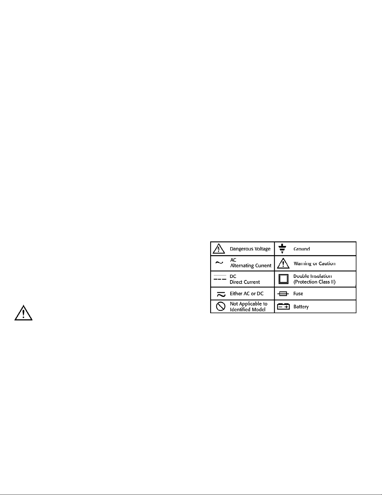
International Symbols
Introduction
The DL235 combines the speed and versatility of a high resolution analog
display with the precision of a digital meter. This meter measures the
True RMS value of Alternating Current (AC) over from 0.3A to 700A. AC
measurements are from 10 Hz to 1 KHz and frequency measurements are
from 0.5 Hz to 10 KHz.
Clamp meters that measure average current flow are inaccurate for
non-linear currents and their measurements may have some differences
from those obtained using this meter.
The DL235 can also measure frequency while measuring current flow
s i m u l t a n e o u s l y . AC and DC voltages and resistances can be measured
and also continuity check is possible with this meter.
Features include
• True RMS
• Soft mode reduces fluctuations in amp
• Crest mode will display 1/2 wave peak
• MIN/MAX record
• 3-3/4 digit 4000 count LCD display
• Auto or manual ranging
• Data hold
• Low battery indication
• Auto power off
• Ruggedized to withstand a 10’ drop
Safety Notes
Before using this meter, read all safety information carefully. In
this manual the word "WARNING" is used to indicate conditions
or actions that may pose physical hazards to the user. The word
"CAUTION" is used to indicate conditions or actions that may
damage this instrument.
WARNING!
Exceeding the specified limits of this meter is dangerous and can
expose the user to serious or possibly fatal injury.
• DO NOT attempt to measure any voltage that exceeds 600 volts
with this meter - UEi offers numerous alternatives for measuring
high voltage and current
• Voltages above 60 volts DC or 25 volts AC may constitute a
serious shock hazard
• DO NOT attempt to use this meter if either the meter or the test
leads have been damaged. Send unit in for repair by a qualified
repair facility
• Test leads must be fully inserted prior to taking measurements
• Always turn off power to a circuit (or assembly) under test before
cutting, un-soldering or breaking the current path. Even small
amounts of current can be dangerous
DL235-MAN P. 1
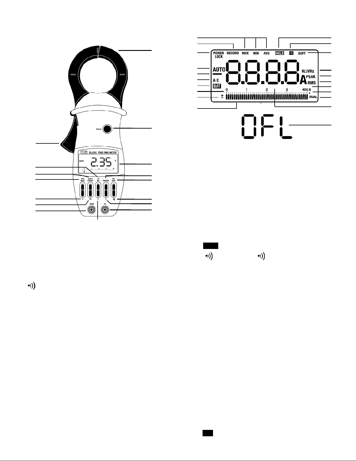
LCD Display Functional Description
14. Soft Cre s t : Select “SOFT” for a running 3-second average, or
CREST half cycle peak amperes.
15. AC/DC: Selects AC or DC mode.
16. Lever: Opens and closes clamp jaws.
17. Record: Displayed (blinking) when “MIN/M AX / A V G “ values are
being recorded. Duration of RE CO R D is limited by battery life.
18. MIN/MAX/AVG: Displayed in “REC ORD” mode by pressing
“MIN/M A X” push-button.
19. : Displayed when “HOL D” push-button has been pressed.
20. : Displayed when “ “ push-button has been pressed.
21. Soft: Displayed when current flow readings or Hz or V readings are
softened out over 3-second interv a l s .
22. KΩVHz: Displayed when measuring ohms or voltage or frequency.
23. Peak: Displayed when current flow readings are in half-cycle
peak amperes (CRES T m o d e ) .
24. RMS: Displayed when current reading is in amperes rms.
25. Off-Scale Arrow: Displayed when bar graph pointer is off sca l e .
26. Dual: Displayed when measuring frequency in digital and
amperes in bar graph simultaneously.
27. A: Displayed when meter is measuring amperes.
28. Digital Display: Displays 3999 counts, with two decimal points
relative to the two ranges. But, displays 9999 counts in frequency
mode. Display in updated 4 times each second.
29. Pointers: Displayed to indicate position on bar graph scale.
Positions are updated 20 times each second.
30. Analog Display Polarity: Displays + or - when the pointers
are displayed.
31. 0 to 400A: (or 0 to 800A) numeric reference for the bar gra p h .
32. : Displayed when internal battery needs replacing.
C o n t rols and Indicators
1. C l a m p : Opens 2.04 inches (52 mm) to enclose conductors.
2. Hold: Freezes reading in digital display.
3. Display: Liquid crystal display.
4. Range: Selects 0 to 40A, 0 to 400A, or AUTO .
5. On Off: Selects meters power ON or power OFF.
6. : Selects continuity testing mode.
7. Ω: Selects ohms measurement mode.
8. VΩ: Volt, ohms, continuity test input terminal.
9. V: Selects volts measurement mode.
10. COM: Common terminal.
11. Hz: Selects frequency measurement mode.
12. A: Selects aperes measurement mode.
13. MIN/MAX: Selects “REC ORD” mode and displays
recorded MIN / M AX / A V G .
DL235-MAN P. 2
1
18
BAT
HOLD
2
3
4
5
6
7
8
9
10
11
12
13
14
15
16
17
36
35
34
33
32
31
30
29
37
19
20
21
22
23
24
25
26
27
28
29
33. AC: Alternating current or voltage.
34. : A u t o m a t i c ally indicate negative digital displays.
35. Auto: Displayed when autoranging controls bar graph scale (0 to
40A scale, or 0 to 400A scale) and controls position of decimal
point on digital display.
36. Power Lock: Displayed when the “A U T O P O W ER O FF” mode of
the meter has been disabled.
37. Beeper: Beeps for push-button operation or current overload.
38. OFL: O v e r f l ow i ndica t i o n .
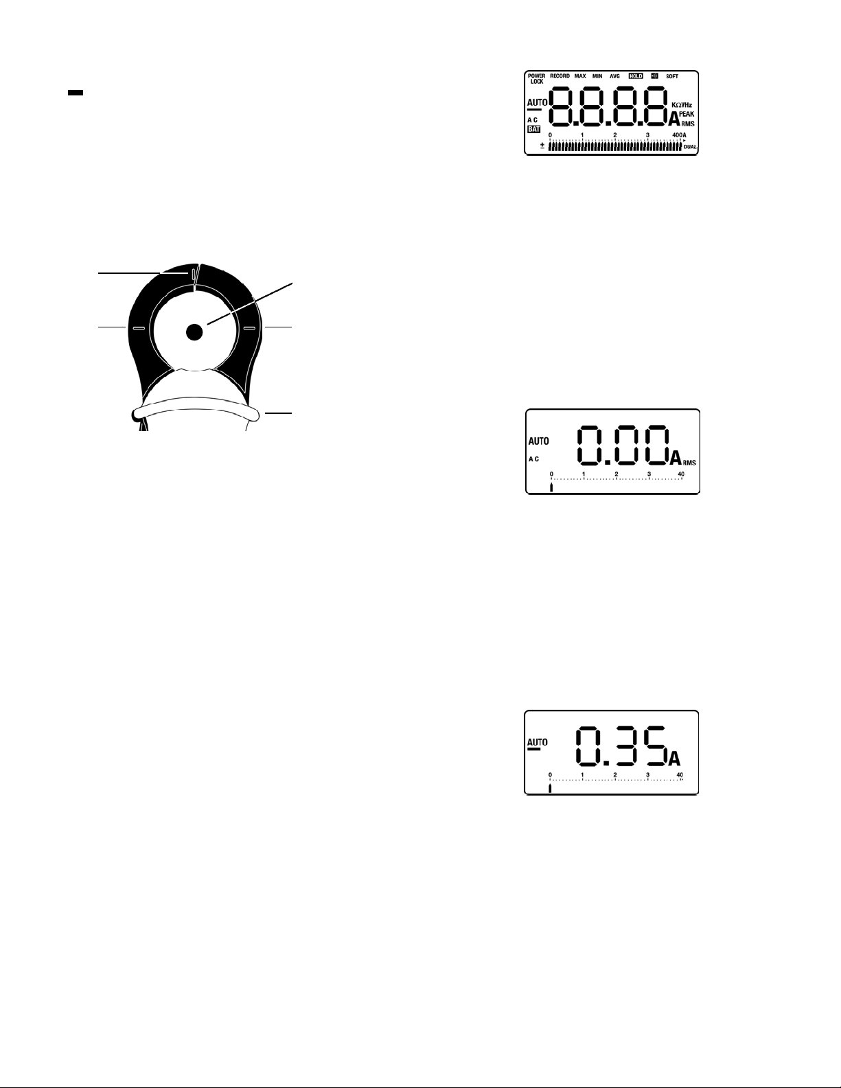
Position the conductor within the jaws at the intersection of the
i n d i c ated marks as much as possible in order to meet this meter’s
a c c u r a c y specifica t i o n s .
If the conductor is positioned elsewhere within the jaws, the max i m u m
additional error resulted is 1.5 percent.
Operating Instructions
Power Up/Self Test
Press and hold the “ON/OFF” push-button in order to power up and
initiate self test (Fig 1). This meter beeps and all LCD segments will turn
on (some segments have nothing to do with this meter) as part of a
self-test routine. Observe a bar graph pointer blinks to indicate the
battery condition while still pressing the “ON/OFF” push-button. The
“Off-Scale” arrow blinks for a battery life in excess of 40 hours and a
corresponding bar graph pointer blinks for a battery life of less than
40 hours. Read the scale as 0 to 40 hours for this battery test. A
pointer under the 3 (6 is not displayed) on the scale, for example,
represents approximately 30 hours of remaining battery life (Fig 1).
Release the “ON/OFF” push-button to initialize this meter.
Replace the battery before using this meter when the battery test gives
a reading of only a few hours or when the low-battery indicator is
displayed on the digital display. If the meter does not turn on, the
battery is missing or worn out. Replace battery.
This meter shuts OFF after 10 minutes if no push-button is pressed, even
if it is making a measurement. To disable the auto power off, press the
“ON/OFF” push-button ( is displayed), when the “ON/OFF”
pressed again , the meter turns OFF.
To use in manual range, press the “RANGE” push-button. Press again
for 2 seconds to return to autoranging mode.
The auto power off feature is disabled in “RECORD” mode.
Measuring AC Amperes
When the meter is turned on, it defaults in the AC amperes mode with
250-ms measurement intervals (AC displayed) and autoranging mode
(AUTO displayed), which automatically selects the proper range for both
the bar scale and the digital display. Press the “RANGE” push-button to
select a fixed scale instead of autoranging. Observe that each press
alternates between the 40A and 400A scales and “AUTO” is no longer
displayed. When the reading is beyond the limits of the digital display,
for example, 40A on a 40A scale, “OFL” appears on the digital display.
Press the “RANGE” push-button for 2 seconds and then release in
order to return to autoranging mode. This meter acknowledges with a
beep sound and displays “AUTO” (Fig 2).
Measuring DC Amperes
Press the “AC/DC” push-button to select the DC amperes measurement
mode (AC disappears on the LCD), but the meter is still in the autora n g i n g
mode (AUTO displayed), unless you press the “RA N GE” push-button to
enter into the manual ranging mode.
When the DC amperes measurement mode is entered, the display reads
a non-zero DC amperes (positive or negative) value due to the presence
of the Earth’s magnetism. This value is variable according to the location
measuring DC amperes (Fig 3).
DL235-MAN P. 3
(Fig 2)
(Fig 3)
POWER
LOCK
(Fig 1)
MARK
MARK
MARK
CONDUCTOR
HAND GUARD
 Loading...