

Page 1
INSTRUCTION MANUAL
DAFM3
Digital Air Flow Meter
1-800-547-5740 • Fax: (503) 643-6322
www.ueitest.com • email: info@ueitest.com
Page 2

TABLE OF CONTENTS
Introduction .......................................................................................... 2
Safety ....................................................................................................... 3
Controls ............................................................................................... 4-5
Operating Instructions
Disable Auto Power Off ................................................................. 5
Selecting Units ................................................................................5
Ft Range ........................................................................................... 5
INCH ................................................................................................. 5
CM ....................................................................................................5
Basic Measurement .................................................................... 5-6
MIN/MAX/AVG ................................................................................ 6
Velocity with Average ....................................................................6
Air Volume Measurement ......................................................... 6-7
Entering Free Area ..................................................................... 7-8
Air Volume: Measurement ............................................................ 9
Low Battery ...................................................................................11
Maintenance
Periodic Service ............................................................................12
Cleaning .........................................................................................12
Battery Replacement ....................................................................12
Troubleshooting ................................................................................13
Specifications ....................................................................................14
Warranty and Service Information ...........................................15
i
Page 3

Introduction
The DAFM3 Anemometer/Psychrometer meter is designed with 6
HVAC/R must have parameters in one instrument. These are included
in a portable battery operated instrument for measuring Humidity,
Air temp., Dew Point, Wet Bulb, Air Velocity and Air Volume. The
sensor is built into the remote fan and is specially protected by a twist
cap. While in operation, open the cap for accurate temperature and
humidity readings.
Features include
• Measures Air Velocity, Temperature and Humidity
• Calculate Wet Bulb, Dew Point, and Air Volume (CFM, CMM)
• Protective twist cap for temperature/humidity sensor
• 8-Point Average for Air Velocity
• 30 Second Average for Air Volume
• Total Volume from multiple outlets
• Large LCD digital display
• Professional remote vane
• English/Metric scales
• Low battery indication
• Fast response
• Microprocessor circuitry for reliability
• Auto Power Off selectable
• Powered by 1 “9V” battery
Material Supplied
• DAFM3 Anemometer/Psychrometer Meter
• Remote Vane
• Batteries (1)9V
• User manual
• Hard carrying case
2
Page 4
Safety Notes
Before using this meter, read all safety information carefully. In
this manual the word “WARNING” is used to indicate conditions
or actions that may pose physical hazards to the user. The word
“CAUTION” is used to indicate conditions or actions that may
damage this instrument.
CAUTION!
Objects striking the fan may damage meter.
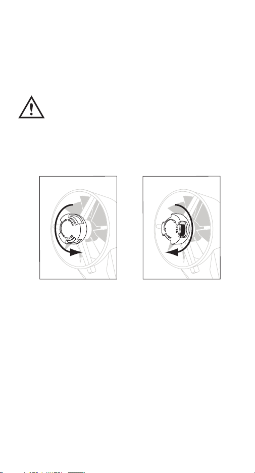
IMPORTANT NOTE:
1. Rotate the protective cover in the center of the fan to open before
measurement to ensure the measured data is correct.
CLOSED
2. The fan and meter are sold as a kit and are calibrated to each
other. Please don’t connect the fan with another DAFM3 or other
similar anemo-psychrometers because the characteristic of each
fan is different.
OPEN
3
Page 5
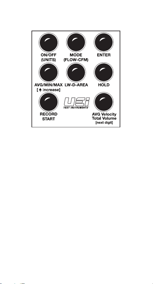
Controls and Indicators
1. 2. 3.
4. 5.
6.
8.7.
1. ON/OFF: Turns ON the meter with auto-sleep mode. Turns OFF
the meter at any mode.
NOTE: When the meter is OFF, press more than four seconds to
enter “UNITS” selection.
2. MODE: Press to select different modes (Temp, DP, WB, RH,
Velocity). Press and hold until beep to select “VOLUME”
function.
3. ENTER: To confirm the setting and calibration.
NOTE: Also used to recall values stored in memory for multi-
point average.
4. MIN/MAX/AVG and UP: Press to view Minimum, Maximum,
and Average value.
• To increase digit during setup for volume.
5. LW-D-AREA: Press to scroll through options for entering area.
Length/Width (LW) for open rectangular duct, Diameter (D) for
open round ductwork, and Area (A) to enter the specified grill
free area (Ak) information.
5
4
Page 6

6. HOLD: Press to hold the current reading, then press this key
again to unlock the held reading.
7. REC/START: In velocity mode, pressing this key to store the
current velocity reading into memory.
• To start measuring volume without waiting to
finish countdown in “Volume” mode.
8. AVG Velocity/Total Volume [next digit]: Press to display
average of stored velocity in standard mode, total volume in
CFM mode. Press a second time to return.
Operating Instructions
Disable Auto Power Off
With the meter off, press and hold “MIN/MAX” then press and hold
“ON/OFF”“ until the meter beeps.
Selecting the units
This function is unique, as it requires the process be started with the
instrument off. If you notice the On/Off button has (Units) below. This
is a “Press and Hold” function. Press this until a beep is heard, and
you will see one of the screens shown below. You can scroll through
these options while displayed by pressing the “Up” button (This is the
function on the AVG/MIN/MAX. button illustrated with the upward
facing arrow).
Select the scales desired and then press the “Enter” key. This will enter
the basic measurement mode.
Basic Measurement
When you first turn the unit on the air velocity is the default value
displayed on the LCD. To review the other basic parameters, press the
“MODE” key. Each parameter will be displayed in turn.
5
Page 7

Basic Measurement (continued)
Parameters Measured will cycle through the following in order
• Air Velocity
• Dry Bulb Temperature
• Dew Point Temperature (DP)
• Wet Bulb Temperature (WB)
• Relative Humidity (RH%)
MIN/MAX/AVG
All modes will capture the average (AVG), minimum (MIN) and
maximum (MAX) value since the meter was powered on. Select AVG/
MIN/MAX by pressing this button. Pressing “MODE” while displaying
“MIN/MAX” or “AVG” will scroll through available readings. Each
mode will also provide a choice of MIN/MAX or AVG.
Velocity with Average
The DAFM3 has the ability to capture up to eight values for velocity,
and then display the minimum, maximum and average of these
readings.
The maximum number of records is 8 points.
1. Store readings while in
the measurement mode by
pressing “RECORD” (up to 8
points of data).
2. Press “AVG Velocity” to view
results.
NOTE: “REC H” will display in
the lower left of the display.
3. Press “MIN/MAX/AVG” to
cycle through the calculated
values.
Measuring Air Flow (volume) with the UEi DAFM3
Air speed is the rate at which the airflow is moving past a specific
point. It is typically measured in feet per minute in our use, but can be
one of many different scales. Aircraft measure in knots, and weather
forecasters will use miles per hour as examples.
6
Page 8

Measuring Air Flow (continued)
Air volume is measured to determine the total amount of air going
through an area in a given amount of time. We are typically looking
for cubic feet per minute (CFM) as it relates to heating or cooling
equipment. To determine this, you must either direct all of the air
through a known area, or use an instrument to measure velocity that
can calculate the CFM from the known area.
To understand we can compare to something more common. Consider
a small stream compared to a large river. A river has a huge area, but
the water may be moving at a low speed, while a stream may have
a higher velocity, but not be very big. If measuring the velocity of
the water only the stream would have a higher number. Some large
rivers move quite slowly, but due to their size move a tremendous
volume of water. If we think about all of the small steams flowing into
a river, we could arrive at the volume of the river by adding all of the
small streams velocity times their area (volume). Also, if we knew the
area that the river was occupying, we could determine the volume by
measuring the average speed of the water flow and multiplying by the
rivers area. This would then give us the total volume of water flowing
past a specific point.
Free Area (Ak value for a grill)
Grills or registers all have an area associated with all of the openings.
Grill manufactures refer to this as free area or effective area. They
perform extensive testing to determine the total area that is open to
air flow, and is effectively free for the air to flow through. Without this
number it is difficult to determine airflow by measuring velocity, but it
can be estimated for comparison purposes.
What exactly is free area, and how does it relate to airflow and registers
or grills? In open ductwork the free area is simply the open area of the
duct. For a rectangular grill this is determined by length times width.
A 12” by12” rectangular duct that is open has an area of 144 square
inches (length x width). If we want this in square feet we can divide the
result by 144 (144 square inches in each square foot). In this example
the free area is one square foot.
7
Page 9

A register example is 4” by 10”. The area of
12”
this in square inches is 4 x 10 = 40 square
inches. Next convert that to square feet
12
dividing by 144 results in 0.278 square feet.
This would give the total area if it were open,
but because the grill covers a portion of this
we need to estimate the amount of area that is
really open.
Area is length x width
12”x12”= 144 sq. inches
Converting to sq. ft.
144 sq. inches = 1 sq ft.
Below is an example of the steps needed to determine this area:
4”
10”
On a grill, the overall dimensions are not open, or “Free Area.” Entering
dimensions on this would cause a large error. For best results use the
Ak specification from grill manufacturer.
If needed an estimation may be used for comparison
First calculate the total free area of the grill, then take a percentage of
that to enter into the instrument.
On this 4x10 grill, we had calculated the total area At 0.278 square feet.
If we estimate only 70% of the area is truly open, the are would be
0.278 x 0.70 = 0.195 sq. feet
One estimation method would be to measure the area of the louvers
and use length x width. There will still be errors using this approach,
but in comparison analysis the error will be small.
Entering Information into the DAFM3
The first thing to notice is the keypad
labels have two different items under
most buttons. The top line is the activity
that occurs on a short press of the button.
The second (in brackets) line is the activity
that occurs on a long press. This is key to
understanding how to navigate through
the DAFM3 during use.
8
Page 10

Advanced Measurement Mode (Volume)
The DAFM3 can calculate the air volume, and display the result after
taking a 30 second average. The DAFM3 only measures the velocity of
the airflow, so entering an area into the meter is critical. This is also
one of the most involved portions of the DAFM3 operation.
Note: If the Enter key is pressed when trying to advance to “D”
(Diameter) or “AREA” by accident, the only method to recover is to
power the meter off and then back on.
Selecting the method to enter area
Use the following guide to determine the proper method;
1. LW (Length and Width) – Use for open square duct
2. D (Diameter) – Use for open round duct
3. AREA (Free Area) – Use when measuring at a grill.
For best results obtain the Ak or effective area from the grill
manufacture. If this is not available, estimate based on the information
listed earlier in this guide.
To access the desired mode for entering area first enter volume mode
by pressing and holding the MODE button until it beeps. Next scroll
through the options by pressing the “LW-D-Area” button. Icons in the
lower left will indicate you what method of area is currently selected.
The steps are as follows;
1. Press and hold “MODE” to change
to the volume (CFM) mode. The below
screen should appear. (This is the first
screen for the LW dimensions) Note the
“L” in the lower left corner indicating
Length is expected.
2. Press “LW-D-Area” to advance to
the diameter dimension entrance screen.
The icon in the lower left will now be
a “D” to indicate this is now expecting
Diameter.
3. Press “LW-D-Area” to advance
to the area dimension entrance screen.
The icon in the lower left will now be
“AREA” to indicate this is now expecting
Free Area.
9
Page 11

Note: If when trying to advance from LW or D to AREA the “ENTER”
key is pressed it will accept the displayed value in advance to the
20-second countdown. If this is done in error turn the meter off and
start the process at the beginning.
Entering Area
Length/Width
After you decide if you will be using
LW (Length and Width for an open
square duct) D (Diameter for open
round duct), or AREA (Effective area
of a grill – Ak value) you will need to
enter the area. The procedure below
is for the LW entrance mode, but is
the same for all three methods.
To enter the volume mode, press and hold MODE until the unit beeps.
The previous screen will be appear.
This screen is used to enter length
(note small “L” in the lower left corner).
Changing Value Displayed:
One digit will be flashing. Change this
digit by pressing the Min/Max button
(the small triangle indicates increase
or up). When the digit is as desired,
press the lower right button (Next Dgt)
to move the flashing digit one position
left. You can repeatedly press this to
cycle through all of the digits if you
have incorrectly entered a value.
After the length is entered, press “Enter” briefly. This will accept the
value displayed, and move to the Width screen. The screen is very
similar to the length screen, but has a “W” in the lower left.
Enter the Width in the same manner as you entered the length using
the “Min/Max – Up” and “Next Dgt” buttons. When complete you will
press “Enter” briefly to accept this value.
The meter will now enter a 20 second
countdown, allowing you time to
position the air vane in front of the
opening to be measured. The screen
shown here will be displayed.
Note: If you wish to skip this wait
period, press the “Record/Start” key.
10
Page 12

After the 20 second countdown, the
meter will enter a 30 second average
sample period. The immediate air
volume is displayed as measurements
are made, with the meter displaying
an average at the end of the 3 0
seconds. During the sample time, the
following screen will be displayed.
After the sample is complete, the meter will display the average volume
from your test area. To continue on to the next register, press “ENTER”
briefly, then move to the proper entrance method by pressing the
“LW-D-Area” button. The value last entered will be saved to reduce the
time required to measure air volume on multiple outlets that have the
same characteristics.
Diameter – Enter diameter using the inch scale, or divide diameter by
12 to convert inches to feet.
Free Area – Enter value direct from grill engineering data provided by
grill manufacture (recommended)
Total Volume – At the end of a test, the “Total Volume” button can be
pressed to display a total of all measurements made since entering this
mode. The display will show total volume with a number in the upper
left corner of the display to indicate the number of air outlets that have
been measured and that are being used for a total average volume. To
return to the last volume measurement press the “Total Volume” button
again.
Low-Battery
Two level battery indication:
Level 1: Battery indicator will flash at level 1. In this situation, the
meter will work normally, however users should prepare to
replace the batteries.
Level 2: Battery indicator will always display on the LCD. In this level
change batteries immediately.
11
Page 13

Maintenance
Periodic Service
WARNING!
Repair and service of this instrument is to be performed by qualified
personnel only. Improper repair or service could result in physical
degradation of the meter. This could alter the protection from
electrical shock and personal injury this meter provides to the
operator. Perform only those maintenance tasks that you are
qualified to do.
Cleaning
Periodically clean your meter’s case using a damp cloth. DO NOT use
abrasive, flammable liquids, cleaning solvents, or strong detergents as
they may damage the finish, impair safety, or affect the reliability of the
structural components.
Battery Replacement
Remove screw from battery compartment cover on back of meter and
remove cover. Replace battery with a fresh 9 Volt battery paying attention
to polarity position. Replace cover and screw.
9 Volt
12
BACK OF INSTRUMENT
Page 14

Troubleshooting
Power on but Press the power key more than 3 seconds
no display Replace the battery and try again
Remove the battery and wait one minute
Reinstall and try again
E1 The probe is not connected or damaged
E2 The value is underflow
E3 The value is overflow
E4 The original data that is relative to this
value has an error
E5 Out of meter display range
E6 The value is not calculated completely
E11 Humidity Calibration error
13
Page 15

Specifications
Temperature -4˚ to 140˚F (-20˚ to 60˚C)
Accuracy: ±1˚F (+0.6˚C)
Resolution: 0.1˚F (0.1˚C)
Relative Humidity 0 to 100% RH
Accuracy: ±3% at 10 to 60% RH
±5% at other range
Resolution: 0.1%
Dew Point -90˚ to 158˚F (-68˚ to 70˚C)
Accuracy: ±3% at 10 to 60% RH
±5% at other range
Resolution : 0.1˚
Wet Bulb -7.6˚ to 158˚F (-22˚ to 70˚C)
Temperature Accuracy: ±3% at 10 to 60% RH
±5% at other range
Resolution : 0.1˚
Air Velocity 0.3 to 35 m/s (1 to 114 ft/s)
Accuracy: ±5%
Resolution : 0.1% m/s
Air Volume 0 to 99999 m /s (0 to 99999 cfm)
Accuracy: ±5%
Resolution: 0.1(0 - 9999.9) or
1 (10000 - 99999)
Power (1) 9V Alkaline battery or
9V > 200mA adapter
Dimensions Meter: 175 x 70 x 33 mm
Vane: 170 x 77 x 40 mm
3
14
Page 16

DAFM3
®
Digital Air Flow Meter
Limited Warranty
The DAFM3 is warranted to be free from defects in materials and
workmanship for a period of one year from the date of purchase.
If within the warranty period your instrument should become
inoperative from such defects, the unit will be repaired or replaced
at UEi’s option. This warranty covers normal use and does not
cover damage which occurs in shipment or failure which results
from alteration, tampering, accident, misuse, abuse, neglect or
improper maintenance. Batteries and consequential damage
resulting from failed batteries are not covered by warranty.
Any implied warranties, including but not limited to implied
warranties of merchantability and fitness for a particular
purpose, are limited to the express warranty. UEi shall not be
liable for loss of use of the instrument or other incidental or
consequential damages, expenses, or economic loss, or for any
claim or claims for such damage, expenses or economic loss.
A purchase receipt or other proof of original purchase
date will be required before warranty repairs will be rendered.
Instruments out of warranty will be repaired (when repairable) for
a service charge. Return the unit postage paid and insured to:
1-800-547-5740 • FAX: (503) 643-6322
www.ueitest.com • Email: info@ueitest.com
This warranty gives you specific legal rights. You may also have
other rights which vary from state to state.
PLEASE
RECYCLE
Copyright © 2011 UEi DAFM3-MAN 6/11
 Loading...