


U3018WCOL01
U-Line U-3018WCOL-01, U-3018WCS-13, U-3018WCS-00, U-3018WCS-01, U-3018WCS-15 Install Manual
...
®
INSTALL GUIDE
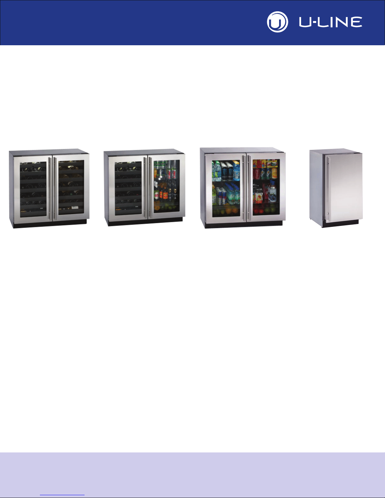
MODULAR 3000 SERIES
WINE CAPTAIN®
MODELS
U-3018WCOL-00
U-3018WCOL-01
U-3018WCS-00
U-3018WCS-01
U-3018WCS-13
BEVERAGE
CENTERS
U-3024BEVOL-00
U-3024BEVOL-01
U-3024BEVS-00
U-3024BEVS-01
U-3036BVWCOL-00
GLASS DOOR
REFRIGERATORS
U-3018RGLOL-00
U-3018RGLOL-01
U-3018RGLS-00
U-3018RGLS-01
U-3018RGLS-13
REFRIGERATORS
U-3018RFOL-00
U-3018RFOL-01
U-3018RFS-00
U-3018RFS-01
U-3024RFOL-00
U-3018WCS-15
U-3024WCOL-00
U-3024WCOL-01
U-3024WCS-00
U-3024WCS-01
U-3036WCWCOL-00
U-3036WCWCS-00
U-3036WCWCS-13
THE MODULAR 3000 SERIES ARE INTENDED FOR BUILT IN INSTALLATIONS ONLY
U-3036BVWCS-00
U-3036BVWCS-13
U-3018RGLS-15
U-3024RGLOL-00
U-3024RGLOL-01
U-3024RGLS-00
U-3024RGLS-01
U-3036RRGLOL-00
U-3036RRGLS-00
U-3036RRGLS-13
U-3024RFOL-01
U-3024RFS-00
U-3024RFS-01
U-3036RROL-00
U-3036RRS-00
The Built-In Undercounter Leader Since 1962 U-LINE.COM

1 Table of Contents
Safety Precautions
Safety Alert Definitions ........................................................................................................................................ 1
General Precautions..............................................................................................................................................1
Inspect & Plan
Product Registration .............................................................................................................................................2
Product Description..............................................................................................................................................2
Exterior Cleaning................................................................................................................................................... 2
Prepare Site
Electrical Specifications.........................................................................................................................................3
Cut-Out Dimensions ............................................................................................................................................3
3018 Series................................................................................................................................................... 3
3024 Series................................................................................................................................................... 3
Product Dimensions
Door Swing Dimensions
3000 Series Doors
3000 Series Overlays
3000 Series Anti-Tip Bracket
Level & Install
3036 Series................................................................................................................................................... 3
3018, 3024 & 3036 Series......................................................................................................................... 4
Other Site Requirements.....................................................................................................................................5
Side-By-Side Installation ............................................................................................................................ 5
Power Supply............................................................................................................................................... 5
Environmental Requirements................................................................................................................... 5
Door Alignment and Adjustment....................................................................................................................... 6
Overlay / Frame Overlay Panel ..........................................................................................................................7
Panel Preparation........................................................................................................................................ 7
Panel Installation ......................................................................................................................................... 8
Overlay Grille .........................................................................................................................................................9
Anti-Tip Brackets Installation............................................................................................................................11
Leveling Information............................................................................................................................................13
Installation..............................................................................................................................................................13
Relocating the Shelves ............................................................................................................................. 13
Installation Troubleshooting................................................................................................................... 13
IMPORTANTIMPORTANT
DANGER
WARNING
CAUTION
2 Safety Precautions
DANGER
WARNING
WARNING
CAUTION
IMPORTANTIMPORTANT
• PLEASE READ all instructions before installing,
operating, or servicing the appliance.
General Precautions
Use this appliance for its intended purpose only. The 3000 model
series is intended for BUILT IN
brackets MUST be installed. Follow these general precautions
with those listed throughout this guide:
installation only. Anti tip
• Proper installation procedures must be followed when
completing an installation or relocation of a unit.
Consult the installation guide before any installation
begins. U-Line contact information appears on the rear
cover of this guide.
• This unit requires connection to a dedicated 15 Amp
grounded (three-prong), polarized receptacle.
Receptacle should be installed by a qualified electrician,
compliant with applicable electrical codes.
Safety Alert Definitions
Throughout this guide are safety items labeled with a Danger,
Warning or Caution based on the risk type:
Danger means that failure to follow this safety statement will
result in severe personal injury or death.
RISK OF CHILD ENTRAPMENT. Before you throw away your
old refrigerator or freezer, take off the doors and leave shelves
in place so children may not easily climb inside.
SHOCK HAZARD - Electrical Grounding Required.
• Never attempt to repair or perform maintenance on
the unit until the electricity has been disconnected.
• Never remove the round grounding prong from the
plug and never use a two-prong grounding adaptor.
• Altering, cutting of power cord, removal of power
cord, removal of power plug, or direct wiring can
cause serious injury, fire and or loss of property and
or life, and will void the warranty.
• Never use an extension cord to connect power to the
unit.
• Always keep your working area dry.
Install provided Anti-Tip kit on all models. Units
may NOT
be installed as free standing. Serious
personal injury could occur.
Warning means that failure to follow this safety
statement could result in serious personal injury,
property or equipment damage.
Caution means that failure to follow this safety statement
may result in minor or moderate personal injury, property
or equipment damage.
• Use care when moving and handling the unit. Use gloves
to prevent personal injury from sharp edges.
• If your model requires defrosting, DO NOT use an ice
pick or other sharp instrument to help speed up
defrosting. These instruments can puncture the inner
lining or damage the cooling unit. DO NOT use any type
of heater to defrost. Using a heater to speed up
defrosting can cause personal injury and damage to the
inner lining.
• Do not lift unit by door handle.
• Never install or operate the unit behind closed doors.
Be sure front grille is free of obstruction. Obstructing
free airflow can cause the unit to malfunction and will
void the warranty.
• Failure to clean the condenser every six months can
cause the unit to malfunction. This could void the
warranty.
• Allow unit temperature to stabilize for 24 hours before
use.
• Do not Block any internal Fans
Use only genuine U-Line replacement parts. Imitation
parts can damage the unit, affect its operation or
performance and may void the warranty.
1 U-Line 3000 Series Product Features
3 Inspect & Plan
IMPORTANTIMPORTANT
WARNING
Product Registration
You have received a carton containing your 3000 series unit with a
package inside containing a Use and Care Guide and a Product
Registration Card. Please complete and mail the Product
Registration Card or register online at www.U-LineService.com.
Once your unit is installed, keep the Use and Care Guide and this
Installation Guide in a safe place for future reference.
Product Description
This installation guide covers the following models.
U-3018RGLOL-00 U-3024RGLS-00
U-3018RGLOL-01 U-3024RGLS-01
U-3018RGLS-00 U-3024RFOL-00
U-3018RGLS-01 U-3024RFOL-01
U-3018RGLS-13 U-3024RFS-00
U-3018RGLS-15 U-3024RFS-01
U-3018RFOL-00 U-3024WCOL-00
U-3018RFOL-01 U-3024WCOL-01
U-3018RFS-00 U-3024WCS-00
U-3018RFS-01 U-3024WCS-01
U-3018WCOL-00 U-3036RRGLOL-00
U-3018WCOL-01 U-3036RRGLS-00
U-3018WCS-00 U-3036RRGLS-13
U-3018WCS-01 U-3036BVWCOL-00
U-3018WCS-13 U-3036BVWCS-00
U-3018WCS-15 U-3036BVWCS-13
U-3024BEVOL-00 U-3036WCWCOL-00
U-3024BEVOL-01 U-3036WCWCS-00
U-3024BEVS-00 U-3036WCWCS-13
U-3024BEVS-01 U-3036RRS-00
U-3024RGLOL-00 U-3036RROL-00
U-3024RGLOL-01
Exterior Cleaning
Stainless door panels, handles and frames can discolor
when exposed to chlorine gas, pool chemicals, salt water
or cleaners with bleach.
• Keep your Stainless unit looking new by cleaning with a good
quality all-in-one stainless steel cleaner/polish on a monthly
basis. For best results use Claire Stainless Steel Polish and
Cleaner, which can be purchased from U-Line Corporation
(Part numbers 173348). Frequent cleaning will remove surface
contamination that could lead to rust. Some installations may
require cleaning on a weekly basis.
• Do not clean with steel wool or abrasive pads.
• Do not use cleaners that are not specifically intended
for stainless steel on stainless surfaces (this includes
glass, tile and counter cleaners).
• If any surface discolors or rust appears, clean it quickly with
Bon-Ami or Barkeepers Friend Cleanser and a non-abrasive
cloth. Always clean in the direction of the grain. Always finish
this process with Claire Stainless Steel Polish and Cleaner or
comparable product to prevent further problems.
• Glass surfaces may be cleaned with standard household window
cleaners.
Rust that is allowed to linger can penetrate into the
surface of the stainless steel and complete removal of
the rust may not be possible.
Inspection
Unwrap and inspect the unit on a flat, level surface capable of
supporting its entire weight. If necessary, remove protective film
from Stainless Steel models.
U-Line Inspect & Plan 2
IMPORTANTIMPORTANT
WARNING
IMPORTANTIMPORTANT
4 Prepare Site
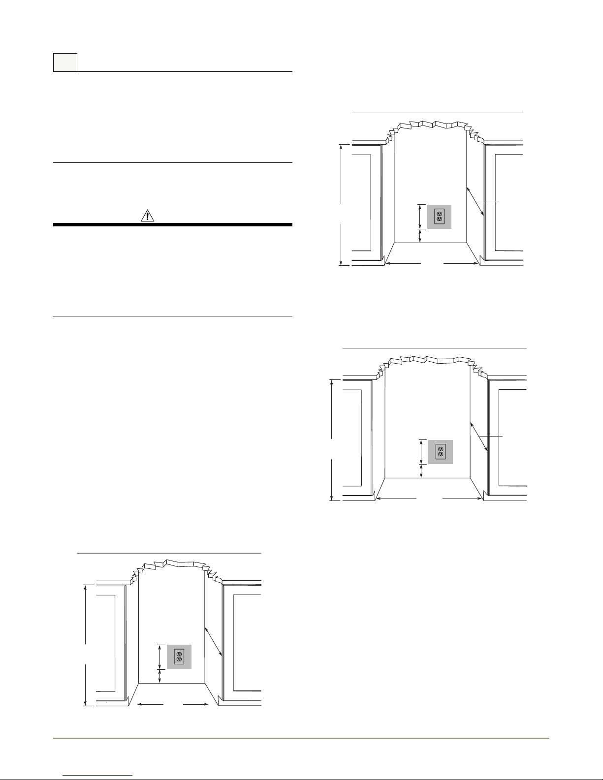
4"
7"
24"
18"
33-7/8"
to
34-7/8"
4"
7"
24"
33-7/8"
to
34-7/8"
23-7/8"
4"
7"
24"
33-7/8"
to
34-7/8"
35 11/16"
Your U-Line product has been designed exclusively for a built-in
installation. When built-in, your unit does not require additional air
space for top, sides, or rear. However, the front grille must NOT
be obstructed and clearance is required for an electrical
connection in the rear.
• Unit can NOT be installed behind a closed cabinet door.
Electrical Specifications
SHOCK HAZARD — Electrical Grounding Required.
• Never remove the round grounding prong from the
plug and never use a two-prong grounding adapter.
• Never use an extension cord to connect power to the
unit.
Electrical installation must observe all state and local
codes. This unit requires connection to a grounded (threeprong), polarized receptacle that has been placed by a
qualified electrician.
The unit requires a grounded and polarized 115 VAC, 60 Hz, 15A
power supply (normal household current). An individual, properly
grounded branch circuit or circuit breaker is recommended. GFCI
(ground fault circuit interrupter) is usually not required for fixed
location appliances and is not recommended for your unit because
a GFCI could be prone to nuisance tripping. However, be sure to
consult your local codes.
3024 Series
Follow the cut-out drawing. The 23-7/8" width allows for ease in
installation and removal of the unit. 24" is the cabinet depth in
most installations.
3036 Series
Follow the cut-out drawing. The 35 11/16" width allows for ease in
installation and removal of the unit. 24" is the cabinet depth in
most installations.
See “Cut-Out Dimensions” for recommended receptacle location.
Cut-Out Dimensions
3018 Series
Follow the cut-out drawing. The 18" width allows for ease in
installation and removal of the unit. 24" is the cabinet depth in
most installations.
U-Line Prepare Site 3
 Loading...