


 Loading...
U-Line 2175-2275DWRR, 2175RF, 2275DWRWS, CLRCO2175, 2115WCOL User Manual
...Service Manual
2010
2115R
2115WC
2115WCOL
2175/2275DWRR
2175R
2175RF
2175WC
2175WCOL
CLR2160
CLRCO2175
CO2175/CO2275DWR
CO2175F
2175BEV
2275DWRWS
2275DWRWOL
2275ZWC
2275ZWCOL
1115R
1115WC
1175BEV
1175R
1175WC
ADA24R
Entertain with U-Line Elegance |
www.u-line.com |

Section 1 - General Information
INTRODUCTION
Three generations of pride and quality manufacturing and design improvements are built into all U-Line products. The result: U-Line leads the market with innovative technology and superior craftsmanship.
This manual contains specific instructions for servicing the U-Line Products which include these models:
ÉCHELON MODELS
2115R
2115WC
2115WCOL
2275DWRR
2175R
2175RF
2175WC
2175WCOL
CLR2160
CLRCO2175
CO2275DWR
CO2175F
2175BEV
2275DWRWS
2275DWRWS
2275ZWC
2275ZWCOL
ORIGINS MODELS
1115R
1115WC
1175BEV
1175R
1175WC
ADA24R
POTENTIAL PROBLEMS WITH HFC-134A
This service manual has been written to cover products manufactured with HFC-134A. HFC-134A compressors receive a synthetic based ester oil charge. The hygroscopic (water attraction) property of ester oil is many times greater than the mineral oils previously used with CFC-12. High system moisture causes the formation of acids and alcohol which can damage the compressor. Systems should not be left open for more than fifteen (15) minutes at any time as humidity from the air will enter the system. To ensure system dehydration, the system should be pulled down to 100 microns and vacuum pump oil (mineral oil) must not be allowed to enter the system.
Cleanliness of the system is extremely important. The presence of residues (chlorinated or greasy residues, mineral oil, or impurities) can lead to capillary tube restrictions, oil return problems and compressor damage. Do not use flux on brazed joints.
IMPORTANT
Check for the latest service related information at U- LineService.com. The Technical Knowledge base is continuously updated and can be accessed anytime. Each U-Line product has a unique method of installation, but it is consistent with U-Line’s methods and requirement. Follow the installation guidelines for the U-Line product you are installing.
1-1

Section 1 - General Information
TABLE OF CONTENTS
SECTION 1 - GENERAL INFORMATION |
|
Introduction .................................................................................................................................................................. |
1-1 |
Potential Problems With HFC-134A....................................................................................................................... |
1-1 |
Safety Precautions ....................................................................................................................................................... |
1-4 |
Safety Alert Definitions .................................................................................................................................... |
1-4 |
General Precautions ......................................................................................................................................... |
1-4 |
U-Line Corporation Limited Warranty................................................................................................................... |
1-5 |
Product Liability Policy................................................................................................................................................ |
1-6 |
Serial Number Format ................................................................................................................................................ |
1-7 |
Warranty Claims Procedure...................................................................................................................................... |
1-7 |
Proof of Purchase......................................................................................................................................................... |
1-7 |
Parts Listing.................................................................................................................................................................... |
1-8 |
SECTION 2 - TROUBLESHOOTING |
|
Customer Call Guide .................................................................................................................................................. |
2-1 |
Refrigeration System Diagnosis Guide .................................................................................................................... |
2-3 |
Thermistor Types......................................................................................................................................................... |
2-3 |
Troubleshooting ........................................................................................................................................................... |
2-4 |
SECTION 3 - SERVICE AND REPAIR |
|
Operation ...................................................................................................................................................................... |
3-1 |
CLR2160 ............................................................................................................................................................. |
3-1 |
CLRCO2175 ...................................................................................................................................................... |
3-4 |
2175R/2115R/2175WC/2115WC/2175BEV/2175DWRR/2275DWRWS/2275ZWC |
|
(Includes Overlay Models) ............................................................................................................................ |
3-14 |
CO2175F/2175RF/CO2175DWR ............................................................................................................... |
3-17 |
1175R/1115R/1175WC/1115WC/1175BEV/ADA24R ........................................................................... |
3-27 |
Operating Environmental/Climate Control Requirements ............................................................................. |
3-29 |
For All - Except WC, DWRWS, BEV Center, CODWR & 2275ZWC/2275ZWCOL ................. |
3-29 |
For WC, DWRWS, CODWR, BEV, CLRCO & 2275ZWC/2275ZWCOL ..................................... |
3-29 |
Échelon Keypad Options ............................................................................................................................... |
3-29 |
Échelon Service Menu .................................................................................................................................... |
3-32 |
Error Codes ..................................................................................................................................................... |
3-34 |
Échelon Service Quick Reference Card ..................................................................................................... |
3-36 |
Échelon Electronic Control Quick Reference Guide ............................................................................. |
3-37 |
Origins Electronic Control ............................................................................................................................ |
3-38 |
Origins Keypad Options ................................................................................................................................. |
3-38 |
Origins Service Menu ..................................................................................................................................... |
3-39 |
Error Codes ..................................................................................................................................................... |
3-39 |
Origins Electronic Control Quick Reference Guide .............................................................................. |
3-40 |
Refrigeration System Diagnosis Guide ....................................................................................................... |
3-41 |
Defrost Information - All models .......................................................................................................................... |
3-41 |
Specifications .............................................................................................................................................................. |
3-42 |
CLR2160 ........................................................................................................................................................... |
3-42 |
CLRCO2175 .................................................................................................................................................... |
3-43 |
2175R/2115R/2175WC/2115WC/2175BEV2175WRR/2175DWRWS/2275ZWC ........................ |
3-44 |
CO2175F/2175RF/CO2175DWR ............................................................................................................... |
3-45 |
1175R/1115R/1175WC/1115WC/1175BEV/ADA24R ........................................................................... |
3-46 |
Adjustments and Repair............................................................................................................................................ |
3-47 |
Leveling .............................................................................................................................................................. |
3-47 |
Door Alignment - Échelon Models ............................................................................................................. |
3-47 |
Door Alignment - Origins Models .............................................................................................................. |
3-49 |
Drawer Alignment .......................................................................................................................................... |
3-49 |
Ice Cube Thickness Adjustment .................................................................................................................. |
3-53 |
Parts Replacement .......................................................................................................................................... |
3-54 |
Plumbing - CLR2160 and CLRCO2175 ............................................................................................................... |
3-57 |
SECTION 4 - PARTS |
4-1 |
Parts Listing .................................................................................................................................................................. |
|
Anti-Tip Kit ................................................................................................................................................................... |
4-1 |
CLR2160 ....................................................................................................................................................................... |
4-2 |
CLRCO2175.................................................................................................................................................................. |
4-6 |
1-2

|
|
|
Section 1 - General Information |
|
|
|
|
|
|
|
|
2175R ............................................................................................................................................................................ |
4-14 |
||
2115R ............................................................................................................................................................................ |
4-18 |
||
2175WC/2175WCOL .............................................................................................................................................. |
4-22 |
||
2115WC/WCOL........................................................................................................................................................ |
4-26 |
||
2175BEV ....................................................................................................................................................................... |
4-30 |
||
2275DWRR ................................................................................................................................................................. |
4-34 |
||
2275DWRWS/2275DWRWOL............................................................................................................................. |
4-38 |
||
CO2175F...................................................................................................................................................................... |
4-42 |
||
2175RF.......................................................................................................................................................................... |
4-50 |
||
CO2175DWR............................................................................................................................................................. |
4-56 |
||
2275ZWC/2275ZWCOL......................................................................................................................................... |
4-64 |
||
1175R ........................................................................................................................................................................... |
4-70 |
||
1115R ............................................................................................................................................................................ |
4-74 |
||
1175WC ...................................................................................................................................................................... |
4-78 |
||
1115WC ...................................................................................................................................................................... |
4-82 |
||
1175BEV ....................................................................................................................................................................... |
4-86 |
||
ADA24R ....................................................................................................................................................................... |
4-90 |
||
SECTION 5 - WIRING DIAGRAMS |
|
||
CLR2160 ....................................................................................................................................................................... |
5-1 |
||
CLRCO2175 ................................................................................................................................................................ |
5-1 |
||
2115R, 2115WC, 2175R, 2175WC ........................................................................................................................ |
5-2 |
||
2275DWRWS/2275ZWC ........................................................................................................................................ |
5-2 |
||
2175DWRR .................................................................................................................................................................. |
5-3 |
||
2175RF ........................................................................................................................................................................... |
5-3 |
||
CO2175F ...................................................................................................................................................................... |
5-4 |
||
CO2175DWR .............................................................................................................................................................. |
5-4 |
||
1175R/1115R/1175WC/1115WC/1175BEV/ADA24R ....................................................................................... |
5-5 |
||
1-3
Section 1 - General Information
SAFETY PRECAUTIONS
IMPORTANT
PLEASE READ all instructions completely before attempting to service the unit.
•Proper installation procedures must be followed if this unit is being initially installed, or is moved to a new location after being in service. An INSTALLATION GUIDE for your unit, providing complete installation information is available from U-Line Corporation directly, and must be consulted before any installation is begun. U- Line contact information appears on the rear cover of this guide.
•This unit requires connection to a grounded (threeprong), polarized receptacle that has been placed by a qualified electrician in accordance with applicable electrical codes.
Safety Alert Definitions
Safety items throughout this guide are labeled with a Danger, Warning or Caution based on the risk type:
 DANGER
Danger means that failure to follow this safety statement will result in severe personal injury or death.
 WARNING
Warning means that failure to follow this safety statement could result in serious personal injury or death.
 CAUTION
Caution means that failure to follow this safety statement may result in minor or moderate personal injury, property or equipment damage.
General Precautions
Use this appliance for its intended purpose only and follow these general precautions along with those listed throughout this guide:
 DANGER
RISK OF CHILD ENTRAPMENT. Before you throw away your old refrigerator or freezer, take off the doors and leave shelves in place so that children may not easily climb inside.
 WARNING
SHOCK HAZARD - Electrical Grounding Required.
•Never attempt to repair or perform maintenance on the unit until the electricity has been disconnected.
•Never remove the round grounding prong from the plug and never use a two-prong grounding adapter.
•Altering, cutting of power cord, removal of power cord, removal of power plug, or direct wiring can cause serious injury, fire and/or loss of property and/or life and will void the warranty.
•Never use an extension cord to connect power to the unit.
•Always keep your working area dry.
 WARNING
Failure to use the Anti-Tip Kit when it is included with the product can cause serious personal injury. The Anti-Tip Kit must be installed before the unit is used.
 CAUTION
•Use care when moving and handling the unit. Use gloves to prevent personal injury from sharp edges.
•If your model requires defrosting, DO NOT use any type of heater to defrost. Using a heater to speed up defrosting can cause personal injury and damage to the inner lining.
IMPORTANT
•Do not lift unit by door handle.
•Never install or operate the unit behind closed doors. Be sure front grille is free of obstruction. Obstructing free air flow can cause the unit to malfunction and may void the warranty.
•Failure to clean the condenser every three months can cause the unit to malfunction. This could void the warranty.
•Allow unit temperature to stabilize for 24 hours before use.
•If your model requires defrosting, never use an ice pick or other sharp instrument to help speed up defrosting. These instruments can puncture the inner lining or damage cooling unit.
•Use only genuine U-Line replacement parts. Imitation parts can damage the unit, affect its operation or performance and may void the warranty.
1-4

Section 1 - General Information
U-LINE CORPORATION LIMITED WARRANTY
U-Line Corporation warrants each U-Line product to be free from defects in materials and workmanship for a period of one year from the date of purchase; and warrants the sealed system (consisting of the compressor, the condenser, the evaporator, the hot gas bypass valve, the dryer and the connecting tubing) in each U-Line product to be free from defects in materials and workmanship for a period of five years from the date of purchase. During the initial one-year warranty period for all U-Line products U-Line shall: (1) at U-Lines option, repair any product or replace any part of a product that breaches this warranty; and (2) for all Marine, RV and Domestic U-Line products sold and serviced in the United States (including Alaska and Hawaii) and Canada, U-Line shall cover the labor costs incurred in connection with the replacement of any defective part. During years two through five of the warranty period for the sealed system, U-Line shall: (1) repair or replace any part of the sealed system that breaches this warranty; and (2) for all Marine, RV and Domestic U-Line products sold and serviced in the United States (including Alaska and Hawaii) and Canada, U-Line shall cover the labor costs incurred in connection with the replacement of any defective part of the sealed system. All other charges, including transportation charges for replacements under this warranty and labor costs not specifically covered by this warranty, shall be borne by you. This warranty is extended only to the original purchaser of the U-Line product. The Registration Card included with the product should be promptly completed by you and mailed back to U-Line or you can register on-line at www.U- LineService.com.
The following are excluded from this limited warranty: installation charges; damages caused by disasters or acts of God, such as fire, floods, wind and lightening; damages incurred or resulting from shipping, improper installation, unauthorized modification, or misuse/abuse of the product; customer education calls; food loss/spoilage; door and water level adjustments (except during the first 90 days from the date of purchase); defrosting the product; adjusting the controls; door reversal; or cleaning the condenser.
If a product defect is discovered during the applicable warranty period, you must promptly notify either the dealer from whom you purchased the product or U-Line at P.O. Box 245040, Milwaukee, Wisconsin 53224 or at 414-354-0300. In no event shall such notification be received later than 30 days after the expiration of the applicable warranty period. U-Line may require that defective parts be returned, at your expense, to U- Lines factory in Milwaukee, Wisconsin, for inspection. Any action by you for breach of warranty must be commenced within one year after the expiration of the applicable warranty period.
This limited warranty is in lieu of any other warranty, express or implied, including, but not limited to any implied warranty of merchantability or fitness for a particular purpose; provided however, that to the extent required by law, implied warranties are included but do not extend beyond the duration of the express warranty first set forth above. U-Lines sole liability and your exclusive remedy under this warranty is set forth in the initial paragraph above. U-Line shall have no liability whatsoever for any incidental, consequential or special damages arising from the sale, use or installation of the product or from any other cause whatsoever, whether based on warranty (express or implied) or otherwise based on contract, tort or any other theory of liability.
Some states do not allow limitations on how long an implied warranty lasts or the exclusion or limitation of incidental or consequential damages, so the above limitations may not apply to you. This warranty gives you specific legal rights, and you may also have other rights which vary from state to state.
1-5

Section 1 - General Information
PRODUCT LIABILITY POLICY
Field service technicians are authorized to make an initial assessment. If in the servicer’s judgment
the damage is the result of a product defect, the product would be removed and returned to U-Line in an unaltered condition. The dealer would then be authorized to permanently replace the end-user’s product at no cost to the end-user. Please call U-Line immediately at 800-779-2547 to initiate the RA and product exchange process.
If in the servicer’s judgment the damage is the result of installation issues (water
connection/drain, etc.), the consumer would be so notified and the correction would be made by the servicer or installer without requiring removal of the product. Any claim for damages should be directed to the original installer.
Any U-Line unit involved in an alleged property damage claim must remain unaltered and unrepaired, for evaluation. No service or repairs should be performed on any unit suspected to be involved in a property damage situation. If a unit has been altered or repaired in the field prior to U- Line’s evaluation, any claim for damage may be declined.
If the unit in question is a U-Line CLR or CLRCO with a drain pump, both the unit and the drain pump (regardless of the manufacturer) must be returned to U-Line Corporation.
To complete the damage claim process for the customer, please obtain the following and forward to U-Line at onlineservice@U-Line.com, fax to 414-354-5696 or mail to the address below.
Pictures of the unit, installation and any alleged property damage.
Inquire when the problem first appeared, any prior problems with the product and provide a brief description of the alleged damages.
To expedite the claim process, U-Line will need two damage repair estimates.
Reference the RA number and customer name when providing this information.
If a unit is returned to U-Line, this evaluation will take approximately ten business days. No field service company is authorized to perform this evaluation. When a Return Authorization Number is issued, and the unit has been boxed in a U-Line carton, U-Line should be contacted and then will make arrangements for shipping, or designate a truck line to have the unit shipped freight collect.
If U-Line’s evaluation finds the unit, (or U-Line P60 pump) to be defective, causing the property damage, the damage claim will be reviewed by the U-Line Customer Assurance Department.
If U-Line’s evaluation finds the unit not to be defective, does not repeat a failure or does not leak any water from the U-Line unit or U-Line P60 pump, all claims for damage will be declined.
When a product evaluation is needed, it is the customer’s responsibility to assure that the unit is returned for evaluation. If the customer fails to do so, or has the unit repaired in the field prior to U-Line’s evaluation, any claim for damage will be declined.
8900 N. 55th St. • P.O. Box 245040
Milwaukee, WI 53224-9540
414/354-0300 • Fax: 414/354-7905
Website: www.u-line.com
Leaders In Quality Undercounter Refrigeration
1-6
Section 1 - General Information
SERIAL NUMBER FORMAT
IMPORTANT
Starting October 2009 U-Line Corporation went to a 13 digit serial number. Anything before that date will have 12 digits.
The serial number is divided into four segments. A typical serial number is 0914997-11-0005.
0914997-11-XXXX
Year Shop Month |
Factory Internal |
Order |
Control Number |
Number |
|
The first two digits of the first segment, 09, represents the year the unit was made.
The next four/five digits of the first segment, 14997, represent the shop order number. Order number 14997 is assigned for the Model CLRCO2175B-40 units.
The next two digit segment, 12, represents the month the unit was made.
The last four digit segment, XXXX, is a factory internal control number used at U-Line Corporation.
WARRANTY CLAIMS PROCEDURE
WHEN SUBMITTING CLAIMS FOR WARRANTY
PAYMENT, PLEASE FOLLOW THESE
GUIDELINES.
You can use any form you would normally use to bill your customer (your own computer generated form, Narda, USA, etc.). Claims can also be filed on-line at
www.u-lineservice.com.
The model and serial number MUST be on the claims. Claims will not be paid without a model and serial number.
If you used a part in your repair, you MUST put the part number, the invoice number and where the part came from. Claims will be returned without this information.
If you work on more than one unit per service call please submit a separate claim for each unit.
We track all defects through warranty claims, so please be specific on what the repair was. If it is a system leak, please specify where the leak was.
Please be sure the claim is legible. If the claim form cannot be read, it will be returned, unpaid.
Remember: Door and water level adjustments are 90 day warranties only.
If you are changing out a unit please supply the model and serial number of both units (the unit being replaced and the new unit) and the R.A. number.
Occasionally the customer does not return their warranty cards. In this case we use the date the unit was shipped to our distributor for a beginning warranty date. This may cause the claim to be rejected for a proof of purchase. If you want to check on a purchase date, you may contact the U-Line Corporation Customer Assurance Department at 1-800-779-2547. This will allow you to get a proof of purchase, if needed, before you submit the claim.
At U-Line, parts and labor claims are paid separately. Included in labor are freon and recovery charges, all other parts are handled by the parts department. We require that some parts be returned to us, so we may return them to our vendor. It will be noted on your packing list if we require you to return the part. If a part is to be returned please include a copy of the packing list and a copy of your claim. If the part was purchased at one of our part distributors, you must handle the part warranty with that company. For labor payment please send a readable copy of your claim to U-Line Corporation, P.O. Box 245040, Milwaukee WI, 53224-9540, or fax it to 414-354- 5696. Claims can also be filed on-line at www.u-lineservice.com.
PROOF OF PURCHASE
Proof of Purchase and/or Proof of Install is an important part of the warranty claim process. Sometimes it is difficult to obtain a proper Proof of Purchase/Proof of Install for a number of different reasons:
•The customer does not have a copy (only the original).
•The customer has only their copy of the final Walk Through or sign-off of new construction.
•Other valid reasons that prevent your technician from leaving the job site with a suitable Proof of Purchase/ Proof of Install.
We understand the problem and have modified our Proof of Purchase policy to help you in these situations.
Effective immediately, if a copy of the Proof of Purchase/Proof of Install is not available at the site, the technician should record the following information on the Labor Invoice:
•The name of the selling Dealer
•The date of purchase/installation
•The Order or Invoice number (if available)
•The type of document they saw, i.e. Store Receipt, Closing Papers, Sign-Off of Building Permit, Final Walk Through, etc.
If we have this information on the Labor Invoice, and we have the other information that is needed (correct Serial Number, type of repair, time spent on repairs, parts used in the repair, invoice number for the part, etc.), we will be able to process the invoice for you in a timely manner.
1-7
Section 1 - General Information
PARTS LISTING
How to Order Replacement Parts
1.Refer to Service Parts and locate the illustration(s) for the model you are servicing.
2.Locate the desired part to be serviced and note the item number assigned to it.
3.Locate the item number within the parts list. Note the full description and the corresponding part number. If this is for a warranty unit, indicate and record the model and serial numbers.
4.When ordering parts, it will be necessary to supply Model Number, Serial Number, Part Number, Part Description and in some cases Color or Voltage.
All warranty parts will be shipped at no charge as long as warranty status has been confirmed. If we require that a part be returned to U- line, you will be informaed at the time the order is placed. It will be noted on your packing list if we require you to return a part or if you may field scrap it. If U-Line requires a defective part to be returned, a prepaid shipping label will be included with your new replacement part. When returning parts enclose a copy of your packing list and a copy of your labor claim, showing the model and serial number, and tag or label the part with the nature of the defect.
Our warranty records may not match the customer's information. In this case, a proof of purchase will be required. If you do not have the proof of purchase at the time the order is placed, the part will be sent net 15 days, charged to a Visa or MasterCard or COD if you don't have an open account with U-Line Corporation. When the proof of purchase is provided, we will credit your account (a check will be sent if the part was sent COD).
5. Parts may be ordered on-line, by FAX or phone:
www.U-LineService.com
onlineparts@u-line.com
FAX Number (414) 354-7905
Phone Number (414) 354-0300 or (800) 779-2547;
REPLACEMENT PARTS: Use only genuine U-Line replacement
parts. The use of non-U-Line parts can reduce ice rate, cause water
to overflow from ice maker mold, damage the unit, and can void the
warranty.
1-8

Section 2 - Troubleshooting
CUSTOMER CALL GUIDE
The following guide has been developed to help answer frequently asked questions. It can be used by persons
scheduling service calls. Things to consider before scheduling a service call:
Concern |
Response |
|
|
The unit is not cold enough. |
• Are you familiar with the factory temperature specifications for |
|
your unit? Many factors can cause these temperatures to vary; |
|
ambient temperature, application, amount of use (number of times |
|
and length of time the door or drawers or opened and closed), |
|
etc. |
|
• Is the door or drawers sealing properly? If the door or drawer is |
|
not sealed properly, it allows heat into the unit. U-Line’s warranty |
|
is 90 days for door or drawer adjustments. |
|
• Has the door or drawers been left open? |
|
• Is the condenser clean? U-Line’s warranty does not cover cleaning |
|
the condenser. |
|
• Is the unit behind closed doors or the vent restricted? The front |
|
grille must be free of obstruction. |
|
• Is the unit in an application of heavy usage? Heavy usage or high |
|
ambient temperatures will cause a unit to frost up. |
|
• Did you try adjusting the temperature to a colder level? Adjust to |
|
a colder level. Be sure to allow 24 hours between temperature |
|
control adjustments. |
|
|
Temperature is too cold. |
Check actual temperature versus set-point. |
|
|
The unit is frosting up. |
• Are you familiar with the defrost technology of your unit? |
|
• Is the door or drawers sealing properly? If the door or drawer |
|
is not sealing properly, it allows heat/humidity into the unit. |
|
U-Line’s warranty is 90 days for door or drawer adjustments. |
|
• Has the door or drawers been left open? |
|
• Is the unit in an application of heavy usage? Heavy usage or high |
|
ambient temperatures will cause a unit to frost up. |
|
|
The ice cubes are sticking together. |
• Is the door or drawers sealing properly? This could cause the ice |
|
cubes to stick together. |
|
• Have you tried to shake the ice bucket? If the ice sits without |
|
being used, it will tend to stick together. Shaking the bucket will |
|
usually break the ice cubes apart. If the ice has been sitting for a |
|
long time, you should consider discarding it and make a fresh |
|
batch. |
|
• Does the unit need to be defrosted? |
|
|
Water is leaking out of the unit. |
Have you checked the water connection to the unit? U-Line’s |
|
warranty does not cover installation adjustments. |
|
|
No ice or not enough ice. |
• Are you aware of the factory specifications for ice production? |
|
• Is the ice maker bin arm down? When the arm is up, the ice |
|
maker will not make ice. |
|
• Is the door or drawers sealing properly? U-Line’s warranty is 90 |
|
days for door adjustments. |
|
• Has the ice maker been turned off at the display? |
|
|
2-1
Section 2 - Troubleshooting
CLR2160 Model Only:
Concern |
Response |
|
|
The cubes are wet. |
• The storage bin that holds the ice is not refrigerated. The |
|
cubes in the bin are slowly melting down. The bin will |
|
maintain a temperature of 32°F to 34°F. |
|
|
The floor is very warm in front of my unit. |
• The unit is designed for a built-in application, so warm air |
|
will vent through the front grille, below the door. There |
|
is a safety feature built into the control board that will |
|
shut down the unit if warm air can’t vent or is restricted. |
|
|
No ice, but water pours into the trough and |
• The standpipe needs to be inserted into the drain hole of |
down into the drain. |
the water trough to maintain the proper level of water |
|
inside the trough. |
|
|
When the unit is turned on, all I get is water |
• Once the unit is turned on, there will be a three-minute |
fill. |
water fill. This ensures a fresh batch of water has filled |
|
the trough. If water flows more than three minutes, a |
|
service call will be required. |
|
|
The ice does not come out in a perfect cube |
• When the ice is made, a small hole or “dimple” will |
shape. |
appear on the front or top of the cube. Increasing or |
|
decreasing the time of the freeze cycle will adjust the size |
|
of the dimple. |
|
|
The cubes do not fall into the bin as |
• This is normal. You can use the scoop to break the cubes |
individual cubes. |
apart. |
|
|
Not enough ice is stored in the bin. |
• Make sure unit is level. |
|
|
Drawer Models Only:
Concern |
Response |
|
|
There is excessive condensation on the mullion. |
• The mullion has a heater behind it that should keep the mullion free of |
|
frost and sweat. In extremely humid conditions, some sweat may appear |
|
on the mullion or lower drawer handle/gasket. The heater will not |
|
operate in ambient temperatures over 90°F. |
|
• Drawer units should not be used outdoors or in an area that is not air- |
|
conditioned. |
|
|
Drawer will not close properly. |
• The drawer slides have a self-closing feature which engages when the |
|
drawer is about 1” (25.4mm) from being closed. There may be some |
|
resistance. If the resistance is hard to overcome, try closing the drawers |
|
with more force a couple of times and then try slowly closing the drawers |
|
again. |
|
|
2175DWRR Model Only:
Concern |
Response |
|
|
There is a water leak inside the unit. |
• Make sure the drain is not blocked. Remove any blockage. |
|
|
2-2
Section 2 - Troubleshooting
REFRIGERATION SYSTEM DIAGNOSIS GUIDE
System |
Suction |
Suction |
Compressor |
Condenser |
Capillary |
Evaporator |
Wattage |
Condition |
Pressure |
Line |
Discharge |
|
Tube |
|
|
|
|
|
|
|
|
|
|
|
|
|
|
|
|
|
|
|
|
|
|
|
|
|
|
Normal |
Normal |
Slightly below |
Very hot |
Very hot |
Warm |
Cold |
Normal |
|
|
room |
|
|
|
|
|
|
|
temperature |
|
|
|
|
|
|
|
|
|
|
|
|
|
Overcharge |
Higher than |
Very cold may |
Slightly warm |
Hot to warm |
Cool |
Cold |
Higher than |
|
normal |
frost heavily |
to hot |
|
|
|
normal |
|
|
|
|
|
|
|
|
Undercharge |
Lower than |
Warm-near |
Hot |
Warm |
Warm |
Extremely |
Lower than |
|
normal |
room |
|
|
|
cold near |
normal |
|
|
temperature |
|
|
|
inlet - Outlet |
|
|
|
|
|
|
|
below room |
|
|
|
|
|
|
|
temperature |
|
|
|
|
|
|
|
|
|
Partial |
Somewhat |
Warm - near |
Very hot |
Top passes |
Room |
Extremely |
Lower than |
Restriction |
lower than |
room |
|
warm - Lower |
temperature |
cold near |
normal |
|
normal |
temperature |
|
passes cool |
(cool) or |
inlet - Outlet |
|
|
vacuum |
|
|
(near room |
colder |
below room |
|
|
|
|
|
temperature) |
|
temperature |
|
|
|
|
|
due to liquid |
|
backing up |
|
|
|
|
|
|
|
|
|
Complete |
In deep |
Room |
Room |
Room |
Room |
No |
Lower than |
Restriction |
vacuum |
temperature |
temperature |
temperature |
temperature |
refrigeration |
normal |
|
|
(cool) |
(cool) |
(cool) |
(cool) |
|
|
|
|
|
|
|
|
|
|
No Gas |
0 PSIG to 25” |
Room |
Cool to hot |
Room |
Room |
No |
Lower than |
|
|
temperature |
|
temperature |
temperature |
refrigeration |
normal |
|
|
(cool) |
|
(cool) |
(cool) |
|
|
|
|
|
|
|
|
|
|
THERMISTOR TYPES
Type 1 (Black)
Resistance at 77°F = 10,000 Ohms ± 5%.
Operating range is 185,000 to 650 Ohms. Resistance goes down as temperature increases. Type 1 does not need to be calibrated and can be changed without changing other wires or board.
Type 2 (White)
Resistance at 77°F = 5,000 Ohms ± 5%.
Operating range is 180,000 to 550 Ohms. Resistance goes down as temperature increases. Type 2 does not need to be calibrated and can be changed without changing other wires or board.
2-3
Section 2 - Troubleshooting
TROUBLESHOOTING
 DANGER
Never attempt to repair or perform maintenance on the unit until the main electrical power has been disconnected from the unit.
|
Cause |
|
Remedy |
|
|
|
|
Will not eject ice (water frozen). |
|
|
|
1. |
Control setting too cold. |
1. |
Adjust control warmer. |
2. |
Control inoperable. |
2. |
Replace control. |
3. |
Bin switch inoperable. |
3. |
Replace bin switch. |
4. |
Limit switch defective (open). |
4. |
Replace limit switch. |
5. |
Ice maker assembly motor stalled. |
5. |
Replace motor. |
6. |
Broken wire in ice maker circuit. |
6. |
Repair or replace wiring. |
7. |
Water soaked cabinet insulation. |
7. |
Replace foamed cabinet assembly. |
8. |
Dirty condenser. |
8. |
Clean condenser. |
|
|
|
|
Will not fill with water. |
|
|
|
1. |
Water supply valve closed. |
1. |
Open water supply valve. |
2. |
Water switch inoperable (open). |
2. |
Replace water switch. |
3. |
Solenoid valve inoperable. |
3. |
Replace solenoid valve. |
4. |
Fill tube outlet frozen. |
4. |
Defrost fill tube. |
5. |
Broken wire in water fill circuit. |
5. |
Repair or replace wiring. |
|
|
|
|
Will not stop making ice. |
|
|
|
1. |
Bin switch inoperable (closed). |
1. |
Replace bin switch. |
2. |
Bin arm binding. |
2. |
Lubricate bin arm pivot points or loosen bin arm lever screw. |
|
|
|
|
Water will not stop filling. |
|
|
|
1. |
Water switch inoperable (closed). |
1. |
Replace water switch. |
2. |
Solenoid valve inoperable. |
2. |
Replace solenoid valve. |
3. |
Stalled ice maker motor. |
3. |
Replace motor. |
4. |
Temperature control inoperable. Ice maker is in |
4. |
Replace temperature control. |
|
continuous harvest cycle. |
|
|
|
|
|
|
Ejector blades will not stop turning. |
|
|
|
1. |
Control inoperable. |
1. |
Replace control. Replace hold switch. |
2. |
Hold switch inoperable. |
2. |
Repair or replace wiring. |
3. |
Broken wiring. |
3. |
Replace heater. |
4. |
Short in mold heater. |
4. |
Replace mold heater. |
|
|
|
|
2-4

|
|
|
|
|
|
Section 2 - Troubleshooting |
|
|
|
|
|
|
|
||
|
|
|
|
|
|
|
|
|
|
|
|
|
|
|
|
|
|
|
|
Cause |
|
Remedy |
|
|
|
|
|
|
|||
|
Low ice production. |
|
|
|
|||
|
1. |
Control set too cold. |
1. |
Adjust control warmer. |
|
||
|
2. |
Fan motor stalled. |
2. |
Replace fan motor. |
|
||
|
3. |
Ice cubes too large. |
3. |
Lower water fill adjustment. |
|
||
|
4. |
Dirty condenser. |
4. |
Clean condenser. |
|
||
|
5. |
Bypass valve stuck open (Frost Free units only). |
5. |
Replace bypass valve (Frost Free units only). |
|
||
|
|
|
|
|
|||
|
Not freezing (compressor and fan motors |
|
|
|
|||
|
operating). |
|
|
|
|||
|
1. |
Little or no frost pattern on evaporator. |
1. |
Check for sealed system leak or restriction. |
|
||
|
2. |
Bypass valve stuck open (Frost Free units only). |
2. |
Replace bypass valve (Frost Free units only). |
|
||
|
|
|
|
|
|||
|
Not freezing (compressor not operating - fans |
|
|
|
|||
|
operating). |
|
|
|
|||
|
1. |
Relay inoperable. |
1. |
Replace relay. |
|
||
|
2. |
Overload inoperable (open). |
2. |
Replace overload. |
|
||
|
3. |
Compressor inoperable. |
3. |
Replace compressor. |
|
||
|
|
|
|
|
|||
|
Not freezing (compressor and fans not operating). |
|
|
|
|||
|
1. |
Power cord not plugged in. |
|
|
|
||
|
2. |
Unit turned off. |
1. |
Plug in power cord. |
|
||
|
|
|
|
||||
|
3. |
Control panel inoperable. |
2. |
Press On/Off button to turn unit on. |
|
||
|
|
|
|
||||
|
4. |
Hold switch inoperable (open). |
3. |
Replace control panel. |
|
||
|
|
|
|
||||
|
5. |
Control inoperable. |
4. |
Replace hold switch. |
|
||
|
|
|
|
||||
|
6. |
Broken wire in freeze circuit. |
5. |
Replace control. |
|
||
|
|
|
|
||||
|
7. |
Ejector blades not in freeze position (12:00) |
6. |
Repair or replace wiring. |
|
||
|
|
|
|
||||
|
|
|
|
|
7. |
Manually advance ejector blades to the 12:00 position (test ice |
|
|
|
|
|
|
|
maker and limit switch). |
|
|
|
|
|
|
|||
|
Compressor overheating. |
|
|
|
|||
|
1. |
Condenser air flow restricted. |
1. |
Remove restriction (clean condenser and grille). |
|
||
|
2. |
Condenser fan blade obstructed. |
2. |
Remove blade restriction. |
|
||
|
3. |
Condenser fan motor stalled. |
3. |
Replace fan motor. |
|
||
|
4. |
Compressor inoperable. |
4. |
Replace compressor. |
|
||
|
|
|
|
|
|||
|
Compressor will not stop operating. |
|
|
|
|||
|
1. |
Temperature set too cold. |
1. |
Adjust temperature warmer. |
|
||
|
2. |
Control inoperable. |
2. |
Replace control. |
|
||
|
3. |
Control sensing bulb not sensing mold |
3. |
Fully insert bulb into ice maker tube. Rout bulb away from |
|
||
|
|
temperature. |
|
compressor discharge tube. |
|
||
|
4. |
Evaporator fan stalled. |
4. |
Remove obstruction or replace motor. |
|
||
|
|
|
|
|
|
|
|
2-5

Section 2 - Troubleshooting
|
Cause |
|
Remedy |
|
|
|
|
Water leak (under unit). |
|
|
|
1. |
Water supply line leaking at solenoid valve inlet. |
1. |
Tighten or replace fitting. |
2. |
Water line leaking at solenoid valve outlet. |
|
|
3. |
Water line leaking at fill tube. |
2. |
Replace water line and fitting. |
|
|
||
4. |
Defrost drain line not in drain pan. |
3. |
Tighten clamp or replace fill tube assembly. |
|
|
||
5. |
Crack in water line. |
4. |
Position drain line in drain pan. |
|
|
||
|
|
5. |
Replace water line. |
|
|
|
|
Water leak (inside unit). |
|
|
|
1. |
Ice maker assembly fill cup obstructed. |
1. |
Remove obstruction. |
2. |
Fill ice cup and fill tube out of alignment. |
2. |
Align fill tube and fill cup. |
3. |
Water level too high. |
3. |
Adjust water level. |
4. |
Defrost drain plugged (Frost Free units only). |
4. |
Ice in drain trough (Frost Free units only) (see below). |
|
|
|
|
Excessive frost buildup. |
|
|
|
1. |
Door gasket not sealing properly. |
1. |
Adjust door hinges or replace door gasket. |
2. |
Door out of alignment. |
2. |
Adjust door hinges. |
3. |
Water soaked cabinet insulation. |
3. |
Replace foamed cabinet assembly. |
4. |
Light stays on when door is closed. |
4. |
Repair or adjust light bracket. |
|
|
|
|
Noisy. |
|
|
|
1. |
Copper refrigeration tube touching cabinet. |
1. |
Carefully adjust tubing. |
2. |
Fan blade touching shroud. |
2. |
Adjust fan mounting or shroud. |
3. |
Fan blade obstruction (wiring, foam insulation, |
3. |
Remove obstruction. |
|
packaging material). |
|
|
|
|
|
|
Ice buildup in drain trough or drainage problem. |
|
|
|
1. |
Obstructed drain cup or tube. |
1. |
Clear obstruction. |
2. |
Drain trough heater failed (Frost Free units |
2. |
Replace drain trough heater (Frost Free units only). |
|
only). |
3. |
Reroute drain tube. |
|
|
||
3. |
Kinked drain tube. |
4. |
Align drain trough and drain cup. |
|
|
||
4. |
Drain trough spout and drain cup not aligned. |
|
|
|
|
|
|
Unit will not defrost (Frost Free units only). |
|
|
|
1. |
Bypass coil inoperable. |
1. |
Replace bypass valve. |
2. |
Defrost timer inoperable. |
2. |
Replace defrost timer. |
3. |
Bypass valve inoperable. |
3. |
Replace bypass valve. |
|
|
|
|
Fresh food temperature too cold. |
|
|
|
1. |
Temperature control set too cold. |
1. |
Adjust control to warmer setting (counterclockwise). |
2. |
Bin/Freezer door not closing. |
2. |
Adjust or replace door. |
3. |
Ice bucket not fully inserted. |
3. |
Check for ice behind bucket and push ice bucket in place. |
|
|
|
|
2-6

Section 3 - Service and Repair
OPERATION
CLR2160
GENERAL
Upon initial startup, this unit will enter mode number 5 which is a three-minute water fill regardless of the thermistor temperatures. This only occurs when the initial startup is caused by a power-up of the main board.
Following the three-minute water fill, the unit moves into mode 1 which is the freezing mode. In this mode the water is pumped from the sump trough over the ice maker grid by the circulation pump. This mode typically lasts 10-20 minutes and is regulated by the temperature of the thermistor mounted near the dryer (thermistor 4).
At the conclusion of the freeze cycle the unit will enter mode 2 which is the ice harvest. This harvest can last up to three minutes. During this mode the water trough also refills.
Before the next cycle begins, the custom electronic board determines whether the bin is full. A temperature below 34°F, or a temperature below 35°F for at least one hour will stop the unit from producing ice. The ice-making will always stop at the conclusion of a harvest cycle. It will never stop in the middle of a cycle.
The custom electronic board continuously monitors the optional P60 pump to ensure the drain line is not becoming restricted. In the event of a drain line obstruction, the display interface will show “P1.” If the drain remains restricted the unit will stop ice production until the drain clears. In the event of a partially restricted drain, reduced ice rate will be noticed as the unit continuously turns on and off to eliminate any chances of overfilling the unit with water. If no pump is used the pink jumper needs to be connected to the power cord in its place.
A cleaning mode is available through the user interface by using the key sequence described in the Controls Section. The cleaning mode lasts about 45 minutes, at which point the unit will sit idle for another 15 minutes. During this time the display will show “CL.” At the conclusion of the cycle the unit will automatically turn back on.
THERMISTOR OUTAGE
In the event that a thermistor fails, the unit will stop all functions and display “ER” on the user interface. The exact error can be accessed via the service mode.
SERVICE
The CLR2160 model uses four relays and two thermistors. There is a variety of built-in servicing features to aid in diagnosing the root problem associated with a unit.
To check to see which relays are currently operating, hold the COLDER key and press the ON/OFF key three times. When
entering the sequence, keep the COLDER key pressed until you completely release the ON/OFF key for the third time. The display will cycle through a series of numbers to tell which relays are energized. For example, if the unit was in ice-making mode the display would show 11 20 31 40 51 60 70. The first number is the relay number. In the second number, “1” means on and “0” means off. The relay information can be found in the Control Section.
Each relay can also be turned on and off individually to determine whether or not the board and component are operating. If a board is suspected of not operating correctly you can run through this sequence to ensure each component is turning on and off through the board correctly. Go into service mode and choose option #22. This will cycle every relay on and off showing 10 11 20 21 …. If a component fails to turn on when the relay does, you can verify if there is voltage present by using a voltmeter to check the board output.
To view the actual thermistor readings, hold the WARMER and COLDER keys for about five seconds. The display will cycle through the three thermistors and their temperatures. If a thermistor is unused in a unit it will show a “0” reading. The CLR2160 uses thermistors 2 and 4. For thermistor 4 the display will only show up to “99.” In the event the temperature is higher than this the display will show a flashing “99.”
TROUBLESHOOTING
Error Codes
E1, E2, E9 |
Bad thermistor errors. Replace thermistor. Check |
|
for thermistor errors by accessing “View thermistor |
|
# status (2,19, 20, or 21).” If the error code is |
|
repeated, the thermistor is open or shorted. If a |
|
temperature is displayed, the thermistor is not |
|
defective. |
P1 |
Pump circuit is detecting a drain problem. Consult a |
|
plumber to resolve the issue. If unit does not have a |
|
P60 installed, then the jumper wire is missing in |
|
place of the pump. |
Any other error messages will not affect the operation of the CLR2160 model.
After checking the errors be sure to clear the error log by performing service option 12
3-1
Section 3 - Service and Repair
.
|
L |
|
|
|
|
|
L |
ICEMAKER EVAPORATOR |
C |
|
H |
2276 |
|
|
HIGH PRESSURE |
|
|
|
L |
|
|
|
LOWPRESSURE |
R4: WATER |
|
|
C |
|
L |
TRANSITIONAL PRESSURE |
|
SUPPLY |
|
IN CAPILLARY TUBE |
|
|
|
||
|
|
C |
|
R5: WATER |
|
C |
CIRCULATION PUMP |
|
|
|
L |
|
R4: HOT GAS |
|
|
BYPASS |
|
|
VALVE |
|
|
|
|
L |
H |
H |
C |
R1: CONDENSER |
|
R3: COMPRESSOR |
FAN |
|
|
|
|
|
C |
|
C |
CONDENSER |
|
|
RELAY |
R1 |
R3 |
R4 |
R5 |
|
FUNCTION |
FAN |
COMP |
HOT GAS / |
CIRC PUMP |
|
WATER IN |
|||||
|
|
|
|
||
|
|
|
|
|
|
Mode 1: |
ON |
ON |
OFF |
ON |
|
Ice Making |
|||||
|
|
|
|
||
Mode 2: |
ON |
ON |
ON |
OFF |
|
Ice Harvest |
|||||
|
|
|
|
||
Mode 3: |
OFF |
OFF |
OFF |
OFF |
|
Off |
|||||
|
|
|
|
||
Mode 4: |
OFF |
OFF |
ON/OFF |
ON/OFF |
|
Cleaning |
|||||
|
|
|
|
||
Mode 5: |
|
|
|
|
|
Water Fill & |
OFF |
OFF |
ON* |
OFF |
|
Initial Start-Up |
|
|
|
|
* Normal Start-Up lasts 3 minutes Note: R2, R6 and R7 not used
Figure 1. CLR2160
3-2

Section 3 - Service and Repair
TROUBLESHOOTING (CONTINUED)
No ice
Check the ice bin temperature. If the temperature is in the 3435°F range, the unit is shut down due to low temperature inside. This could be caused by low ambient temperatures or running the unit without a water supply attached.
If the ice bin temperature is above 35°F, the unit should be producing ice. Check to ensure the water trough is full and the pump is operating.
Too much ice
Ensure there is Permagum around the thermistor hole. If there is, proceed to the next step.
The control board is equipped with an adjustment to adjust the level of ice in the bin for customer preference or when used in abnormal installations. With ice stacked to the desired level, check the bin temperature by holding WARMER and COLDER for five seconds. We’ll assume the display showed 38°F for this example. Go to service mode #24 and adjust the setting to that number. This will allow the bin to shut off at this ice level. This temperature needs to be checked after the door has been closed for at least 10 minutes in order for the thermistor temperature to stabilize.
Too little ice
If this is a recurring issue, try adjusting service option #24 colder in 1 or 2° increments until the desired level of ice is achieved.
Ice not sized to customer satisfaction
The thickness of the cubes can be adjusted per the ice thickness section of the manual.
Noise
Some noise from this unit is normal. You may hear the sound of ice dropping into the bin, especially when it is empty. The harvesting processes involves flowing refrigerant and water through valves which may produce a rushing type sound during the harvest. The fan and compressor will produce a continuous low motor noise. If installed, the P60 pump will produce noise at regular intervals as it empties water from the unit. If any of these is objectionable, the unit has an Office mode which can be entered for three hours at a time. During this mode the unit will not produce ice; however, the drain pump will continue to operate.
No water in trough
Ensure the standpipe is fully inserted into the trough.
Check the water valve to see if it is filling the unit.
Watch the water flow over the mold to see if excess water is being splashed out of the trough. This could be the result of improper leveling.
Ice does not release from evaporator
This could be caused by improper leveling or the unit is in need of cleaning.
Poor ice quality
This can be caused by poor incoming water quality. The CLR2160 is designed to produce clear ice in most water; however, abnormal water conditions may result in the need for further filtering.
Water in ice bin
A defect in the drain from the unit will cause water to stop draining from the unit.
Display is showing something other than “Ice,” “ER” or “CL.”
Push one of the keys to see if the display is reset.
Turn unit on and off via the display pad.
Unplug unit, wait one minute and plug back in. If any of these steps return the unit to operation the unit was probably accidently entered into a service mode.
Display is showing a random snaking of characters or a degree symbol is flashing.
The unit is in a special showroom mode. Hold the COLDER key and press the LIGHT key three times to exit.
Display not illuminating but unit operating
First try to plug and unplug the unit. If the display still does not illuminate, there is a four-wire pin connector running from the main board in the base to the display board. One of the wires is disconnected or damaged.
Unit is not operating—no cooling—no fans.
Unplug unit and plug back in. If main board beeps when plugging in the unit then this is most likely a system problem not a board issue.
If board does not beep when plugging in the unit, check the power supply to ensure the outlet is working. Also, check the fuse on the circuit board.
3-3
Section 3 - Service and Repair
CLRCO2175
GENERAL
The U-Line Model CLRCO2175 combines the best of Échelon refrigeration and clear ice-making capabilities into a single unit. A state-of-the-art microprocessor-based controller simplifies operation and troubleshooting. There are four primary modes of operation:
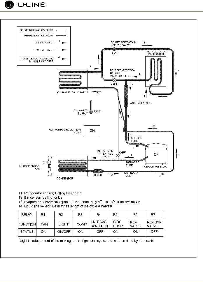
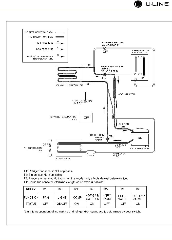
1.Ice Making and Refrigeration (Figure 2).
2.Ice Making and No Refrigeration (Figure 3).
3.Refrigeration and No Ice Making (Figure 4).
4.Ice Harvest/Water fill (No Refrigeration Possible) (Figure 5).
In addition, there are three sub modes of operation:
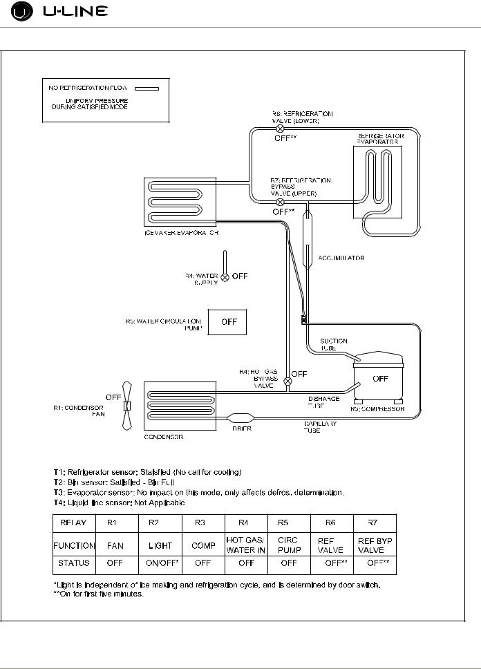
5.Off (Figure 6).
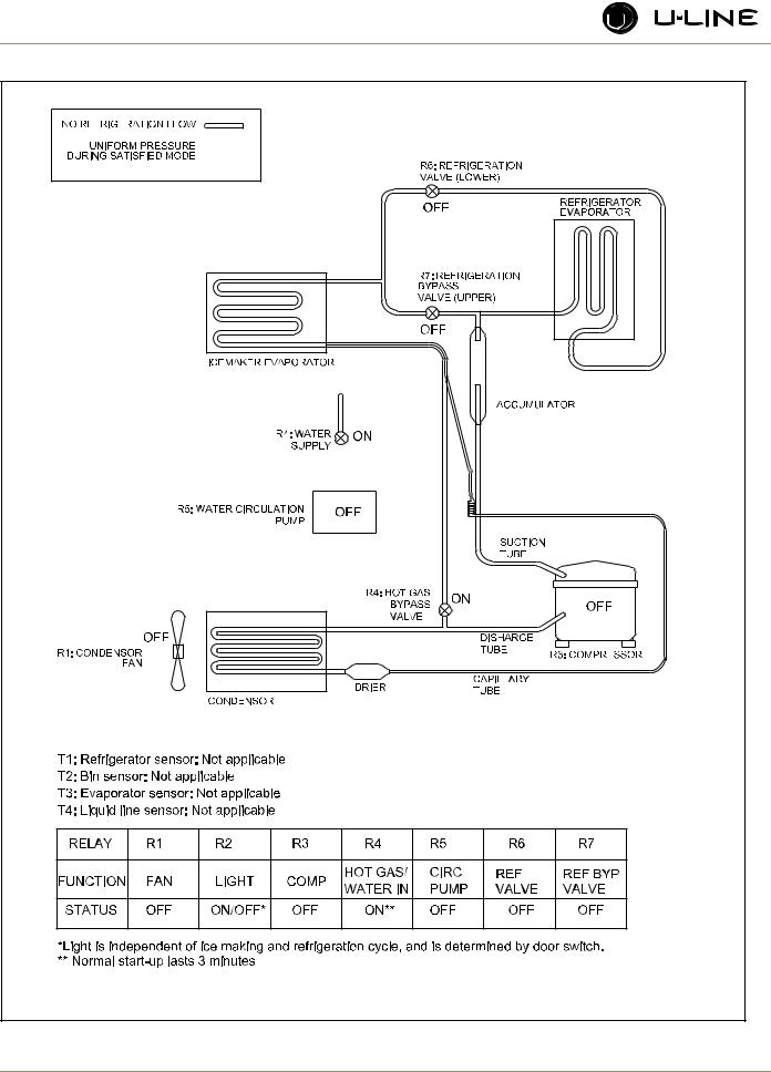
6.Water Fill - No Refrigeration (Figure 7).
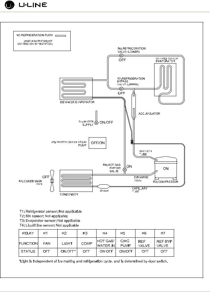
7.Cleaning (No Refrigeration Possible) (Figure 8).
Review the following notes for general information before reading the schematics.
These are some additional general notes and exceptions:
•The controller has a four-minute compressor minimum offcycle regardless of thermistor status, for compressor protection and cycling.
•When making ice, the controller reads liquid line temperature four minutes into the ice-making cycle to determine the length of that ice-making cycle and subsequent harvest length.
•Once an ice-making cycle is initiated, it will continue through to harvest regardless of the bin sensor.
•There is a three-minute water fill cycle when the unit is turned on. Mode 6.
•In order to maintain adequate refrigerator temperature, the unit will sometimes run in the refrigeration only mode, as shown in Mode 3, even if the ice bin sensor is calling for ice. At the end of each ice harvest, the controller checks the refrigerator sensor and if it is warmer than the higher of 42°F, or the set-point, it will go into refrigeration only mode. The refrigerator must be at 42° or setpoint to make ice continuously. Example:
or below the sensor. However, after the first slab of cubes is harvested, the controller will follow the logic defined in 5 above and realizing the refrigerator is too warm, will continue in refrigeration only mode (3) until the requirement is satisfied. Thus, upon start-up, the user will see one slab of ice dropped in about 30 minutes, and then there will be no more ice until the refrigerator reaches 42°F or set-point. (This may be two to three hours depending on ambient conditions.)
•There will also be a water fill cycle after the ice bin has been “full” and then calls to make ice again. This can occur when the refrigerator side is off as shown in Mode 6, or when it is on, which is shown in Mode 8. If the refrigerator side is on, when the fill cycle initiates, it will remain on until the fill cycle is completed, even if the refrigerator sensor is satisfied.
•The controller has a four-degree differential designed into it for the refrigerator sensor, such that when it is set to 38°F, the refrigerator will cool until the refrigerator sensor reads 36°F and will not re-initiate refrigerator cooling until the sensor reaches 40°F. So someone monitoring actual temperature (by pressing WARMER momentarily) may see the refrigerator off when the temperature is a degree warmer than set-point, or refrigerator on when it is a degree below set-point. Refer to
Echelon Keypad.
•There is no high limit cut-out on this unit; however, if the liquid line sensor were to go out of range (approximately 185°F) the ice maker side of the unit will shut down. The refrigerator will continue to run. When the temperature of the liquid falls back in range, the unit will re-initiate operation. The unit will not normally experience this condition up to 110°F, but conditions such as door openings, heavy loading, restricted airflow, dirty condenser or direct sunlight may contribute to reaching this mode.
•Different from the earlier CLRCO2075, this unit uses two relays to control the refrigeration valves. This means that the valves will only be energized when needed.
•There is now a thermistor on the refrigerator evaporator that will sense the evaporator plate temperature. This will allow the unit to fully defrost based on temperature of the evaporator plate during the defrost modes.
Setpoint |
Temperature |
|
38° |
42° or lower |
ice |
38° |
45° |
no ice |
55° |
55° |
ice |
55° |
58° |
no ice |
There is no fill cycle when ice-making re-initiates in this case because the bin sensor has not been satisfied.
•When the initial three-minute fill cycle is complete, the unit will enter ice making and refrigeration mode (1) if the bin is empty
3-4
Section 3 - Service and Repair
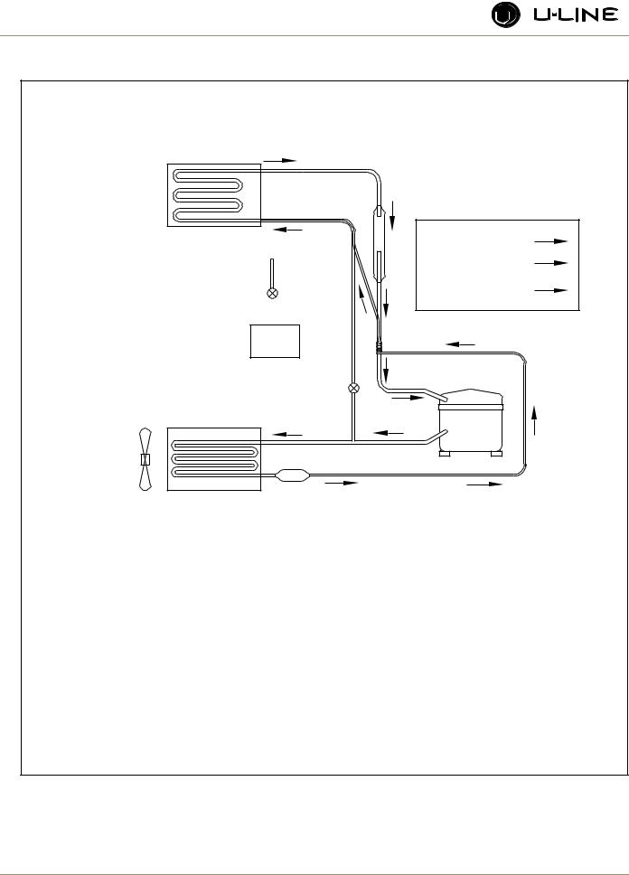
ULIN_0328_A |
Figure 2. CLRCO2175 Mode 1: Ice Making and Refrigeration
3-5
Section 3 - Service and Repair
ULIN_0329_A |
Figure 3. CLRCO2175 Mode 2: Ice Making and No Refrigeration (or Ref Defrost)
3-6

Section 3 - Service and Repair
ULIN_0330_A |
Figure 4. CLRCO2175 Mode 3: Refrigeration and No Ice Making |
3-7
Section 3 - Service and Repair
ULIN_0331_A
Figure 5. CLRCO2175 Mode 4: Ice harvest (No Refrigeration Possible)
3-8
Section 3 - Service and Repair
ULIN_0332_A |
Figure 6. CLRCO2175 Mode 5: Off |
3-9
Section 3 - Service and Repair
Figure 7. CLRCO2175 Mode 6: Water Fill - No Refrigeration Possible (Normal Start-Up) |
3-10 |
Section 3 - Service and Repair
Figure 8. CLRCO2175 Mode 7: Cleaning (No Refrigeration Possible) |
3-11 |

Section 3 - Service and Repair
THERMISTOR OUTAGE
In the event that the condenser thermistor (T4) fails, the unit will stop all functions and display “ER” on the user interface. The exact error can be accessed via the service mode.
If the refrigerator thermistor (T1) fails, the refrigerator will stop operation; however, the ice maker will continue to function. The display will show “ER.” The exact error can be accessed via the service mode.
If the ice bin thermistor (T2) fails, the ice maker will stop functioning; however, the refrigerator will continue to work. The display will show “ER.” The exact error can be accessed via the service mode.
If the refrigerator evaporator thermistor (T3) fails, the unit will function normally; however, defrosting will occur on a timing interval instead of timing and temperature. The display will show “ER.” The exact error can be accessed via the service mode.
SERVICE
The CLRCO2175 model uses seven relays and four thermistors. There is a variety of built-in servicing features to aid in diagnosing the root problem associated with a unit.
To check to see which relays are currently operating, hold the COLDER key and press the ON/OFF key three times. When entering the sequence keep the COLDER key pressed until you completely release the ON/OFF key for the third time. The display will cycle through a series of numbers to tell which relays are energized. For example, if the unit was in ice-making mode, the display would show 11 20 31 40 51 60 70. The first number is the relay number. In the second number, 1 means ON and 0 means OFF. The relay information can be found in the Control Section.
Each relay can also be turned on and off individually to determine whether or not the board and component are operating. If a board is suspected of not operating correctly, you can run through this sequence to ensure each component is turning on and off through the board correctly. Go into service mode and choose option #22. This will cycle every relay on and off showing 10 11 20 21 …. If a component fails to turn on when the relay does, you can verify if there is voltage present by using a voltmeter to check the board output.
To view the actual refrigerator (T1) temperature, hold the WARMER key until the actual temperature is displayed. To view the actual thermistor readings for 2-4, hold the WARMER and COLDER keys for about five seconds. The display will cycle through the three thermistors and their temperatures. If a thermistor is unused in a unit it will show a “0” reading. For thermistor 4 the display will only show up to “99.” In the event the temperature is higher than this, the display will show a flashing “99.”
In the general section the methods to enter some other service modes are available. For the CLRCO2175 model some useful modes are the ICE MAKER OFF MODE, FORCED REFRIGERATOR DEFROST, ICE THICKNESS ADJUST, CLEAN, AND TEMPORARY SHUTDOWN MODE. These can be useful in servicing the unit.
TROUBLESHOOTING:
Error Codes
E1, E2, E7, E8, E9 |
Bad thermistor errors. Replace thermistor. |
|
Check for thermistor errors by accessing |
|
“View thermistor # status (2, 19, 20, or 21).” If |
|
the error code is repeated, the thermistor is |
|
open or shorted. If a temperature is displayed, |
|
the thermistor is not defective. |
E3 |
This will be accompanied by a beep every |
|
minute. This signals that the door has been left |
|
open for longer than 20 minutes. Close the |
|
door to reset. If the light and display do not go |
|
off when the door is closed, check to make |
|
sure the magnet is positioned properly. |
E5 |
This signals that the unit has been above set- |
|
point for more than twelve hours by at least |
|
10°. If the unit was just plugged in leave for 24 |
|
hours to see if the problem is corrected. If it is |
|
not corrected, it is most likely a refrigeration |
|
system issue. |
E6 |
This signals that the refrigerator section has |
|
been at least 10° below set-point for at least |
|
twelve hours. This would most likely be caused |
|
by a bad relay and the circuit board. |
P1 |
Pump circuit is detecting a drain problem. |
|
Consult a plumber to resolve the issue. If unit |
|
does not have a P60 installed, then the jumper |
|
wire is missing in place of the pump. |
After checking the errors, be sure to clear the error log by performing service option 12.
No ice
Check the ice bin temperature. If temperature is in the 34-35°F range the unit is shut down due to low temperature inside. This could be caused by low ambient temperatures or running the unit without a water supply attached.
If the ice bin temperature is above 35°F the unit should be producing ice. Check to ensure the water trough is full and the pump is operating. If the components are not operating, see the service section above.
3-12

Section 3 - Service and Repair
Too much ice
Ensure there is Permagum around the thermistor hole. If there is, proceed to the next step.
The control board is equipped with adjustment to adjust the level of ice in the bin for customer preference or when used in abnormal installations. With ice stacked to the desired level, check the bin temperature by holding WARMER and COLDER for five seconds. We’ll assume the display showed 38°F for this example. Go to service mode #24 and adjust the setting to that number. This will allow the bin to shut off at this ice level. This temperature needs to be checked after the door has been closed for at least 10 minutes in order for the thermistor temperature to stabilize.
Too little ice
If this is a recurring issue, try adjusting service option #24 cooler in 1 or 2° increments until the desired level of ice is achieved.
Ice not sized to customer satisfaction
The thickness of the cubes can be adjusted per the ice thickness section of the manual.
Noise
Some noise from this unit is normal. You may hear the sound of ice dropping into the bin, especially when it is empty. The harvesting process involves flowing refrigerant and water through valves which may produce a rushing type sound during the harvest. The fan and compressor will produce a continuous low motor noise. If equipped, the P60 pump will produce noise at regular intervals as it empties water from the unit. If any of these is objectionable the unit has an Office mode which can be entered for three hours at a time. During this mode the unit will not produce ice; however, the drain pump will continue to operate.
No water in trough
Ensure the stand pipe is fully inserted into the trough.
Check the water valve to see if it is filling the unit.
Watch the water flow over the mold to see if excess water is being splashed out of the trough. This could be the result of improper leveling.
Ice does not release from evaporator
This could be caused by improper leveling or the unit is in need of cleaning.
Poor ice quality
This can be caused by poor incoming water quality. The CLRCO2175 is designed to produce clear ice in most water; however, abnormal water conditions may result in the need for further filtering.
Water in ice bin
A defect in the drain from the unit will cause water to stop draining from the unit.
Display is showing something other than “SP (38),” “ER” or “CL.”
Push one of the keys to see if the display is reset.
Turn unit on and off via the display pad.
Unplug unit, wait one minute and plug back in. If any of these steps returns the unit to operation the unit was probably accidently entered into a service mode.
Display is showing a random snaking of characters or a degree symbol is flashing.
The unit is in a special showroom mode. Hold the COLDER key and press LIGHT three times to exit.
Display not illuminating but unit operating
First try to plug and unplug the unit. If the display still does not illuminate there is a four-wire pin connector running from the main board in the base to the display board. One of the wires is disconnected or damaged.
Unit is not operating—no cooling—no fans.
Unplug unit and plug back in. If main board beeps when plugging in the unit then this is most likely a system problem, not a board issue.
If board does not beep when plugging in the unit, check the power supply to ensure the outlet is working. Also, check the fuse on the circuit board.
Refrigerator not cooling but ice maker working
Check to ensure the refrigerator thermistor is working properly.
Ice maker not operating—no water flowing over mold
The refrigerator needs to be at or below set-point (or 42°F) to start the ice-making process. If the unit is cool enough there could be a defective bin thermistor, defective condenser thermistor or defective solenoid coil.
3-13
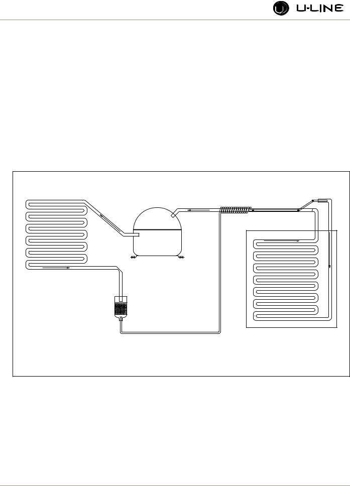
Section 3 - Service and Repair
2175R/2115R
2175WC/2115WC
2175BEV
2175DWRR/2275DWRWS
2275ZWC
(Includes Overlay Models)
GENERAL
Refrigerant is pumped from the compressor to the condenser as a high pressure, high temperature vapor.
As the refrigerant cools in the high pressure condenser, the vapor condenses to liquid. During this phase change, a great amount of heat is rejected with the help of the condenser fan.
The liquid then flows to the dryer where it is strained and filtered.
pressure of the refrigerant is reduced to the evaporating or low side pressure.
The reduction of pressure on the liquid refrigerant causes it to boil or vaporize until it reaches saturation temperature. As the low temperature refrigerant passes through the evaporator coil, it continues to absorb a lot of heat, causing the boiling action to continue until the refrigerant is completely vaporized. It is during this phase that the most heat is absorbed (the cooling takes place) in the refrigerator.
The refrigerant vapor leaving the evaporator travels through the suction line to the compressor inlet. The compressor takes the low pressure vapor and compresses it, increasing both pressure and temperature. The hot high pressure gas is pumped out the discharge line and into the condenser. The cycle continues
From the dryer, the refrigerant flows through the capillary tube which meters the liquid refrigerant to the evaporator. The
COMPRESSOR |
CONDENSER |
DRYER |
EVAPORATOR |
CAPILLARY TUBE |
ULIN_0280_A |
Figure 9. 2175R/2115R/2175WC/2175BEV/2275DWRR/2175DWRR |
3-14
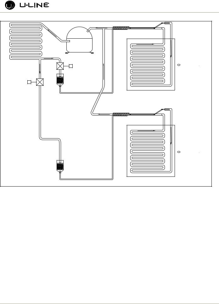
Section 3 - Service and Repair
COMPRESSOR |
|
|
COMPRESSOR |
TOP |
|
|
||
CONDENSER |
TOP |
|
COMPARTMENT |
||
CONDENSER |
||
|
COMPARTMENT |
|
SOLENOID VALVE |
THERMISTOR |
|
THERMISTOR |
||
SOLENOID VALVE |
|
|
DRYER |
|
|
DRYER |
|
|
SOLENOID VALVE |
|
|
SOLENOID VALVE |
|
|
EVAPORATOR |
|
|
EVAPORATOR |
|
|
CAPILLARY TUBE |
|
|
CAPILLARY TUBE |
|
|
|
BOTTOM |
|
|
BOTTOM |
|
|
COMPARTMENT |
|
|
COMPARTMENT |
|
|
THERMISTOR |
|
|
THERMISTOR |
|
DRYER |
|
|
DRYER |
|
|
EVAPORATOR |
|
|
EVAPORATOR |
|
|
CAPILLARY TUBE |
DWR052 |
|
CAPILLARY TUBE |
||
|
DWR052 |
|
Figure 10. 2275DWRWS/2275ZWC |
|
REVIEW THE FOLLOWING NOTES FOR GENERAL INFORMATION.
•The unit is equipped with a four-minute compressor-off cycle.
•The mullion heater is energized on the 2175DWRR whenever the T3 temperature falls below 90°F.
Normal defrosting is based on a time and temperature scale. See chart on page 3-40. Defrost ends if evaporator thermistor reaches stop point or maximum time, whichever comes first.
THERMISTOR OUTAGE (EXCEPT DWRWS & 2275ZWC):
If the refrigerator thermistor (T1) fails, the unit will continue to operate based on a preset time interval of 10 minutes on and 30 minutes off. The display will show “ER.”
If the evaporator thermistor (T2) fails, the unit will operate except it will defrost solely on time and ignore the temperature reading. The display will show “ER.” If the ambient thermistor (T3) fails, the unit will always have the mullion heater energized. The display will show “ER.”
If T1 is not working, unit runs a preset time interval — 10 minutes ON, 60 minutes OFF.
If T2 is not working, unit runs a preset time interval — 10 minutes ON, 60 minutes OFF.
If either T3 or T4 is open, use 90 minutes for defrost length. These errors do not show on the display; they are only logged on the board.
SERVICE
To check to see which relays are currently operating, hold the COLDER key and press the ON/OFF key three times. When entering the sequence, keep the COLDER key pressed until you completely release the ON/OFF key for the third time. The display will cycle through a series of numbers to tell which relays are energized. For example, if the unit was cooling the bottom drawer the display would show 11 20 31 40 50 61 70. The first number is the relay number. In the second number, 1 means ON and 0 means OFF. The relay information can be found in the Control Section.
THERMISTOR OUTAGE (DWRWS & 2275ZWC) |
Each relay can also be turned on and off individually to determine |
|
whether or not the board and component are operating. If a board is |
3-15
Loading...