

Troy-Bilt TB4BP EC Operator's Manual
Operator’s Manual
4-Cycle Backpack Blower
TB4BP EC
TABLE OF CONTENTS
Service Information . . . . . . . . . . . . . . . . . . . . . . . . . . . . . . . . . . . .1
Rules for Safe Operation . . . . . . . . . . . . . . . . . . . . . . . . . . . . . . . .2
Know Your Unit . . . . . . . . . . . . . . . . . . . . . . . . . . . . . . . . . . . . . . . .5
Assembly Instructions . . . . . . . . . . . . . . . . . . . . . . . . . . . . . . . . . .6
Oil and Fuel Information . . . . . . . . . . . . . . . . . . . . . . . . . . . . . . . . .8
Starting/Stopping Instructions . . . . . . . . . . . . . . . . . . . . . . . . . . . .9
Operating Instructions . . . . . . . . . . . . . . . . . . . . . . . . . . . . . . . . .11
Maintenance and Repair Instructions . . . . . . . . . . . . . . . . . . . . . .12
Cleaning and Storage . . . . . . . . . . . . . . . . . . . . . . . . . . . . . . . . . .14
Optional Accessory . . . . . . . . . . . . . . . . . . . . . . . . . . . . . . . . . . .15
Troubleshooting . . . . . . . . . . . . . . . . . . . . . . . . . . . . . . . . . . . . . .16
Specifications . . . . . . . . . . . . . . . . . . . . . . . . . . . . . . . . . . . . . . . .17
Warranty Information . . . . . . . . . . . . . . . . . . . . . . . . . . . . . . . . . .18
SAVE THESE INSTRUCTIONS
SERVICE INFORMATION
DO NOT RETURN THIS UNIT TO THE RETAILER. PROOF OF
PURCHASE WILL BE REQUIRED FOR WARRANTY SERVICE.
For assistance regarding the assembly, controls, operation or
maintenance of the unit, please call the Customer Support Department
at 1-800-828-5500 in the United States or 1-800-668-1238 in Canada.
Additional information about the unit can be found on our website at
www.troybilt.com or www.troybilt.ca.
For service, please call the Customer Support Department to obtain a
list of authorized service dealers near you. Service on this unit, both
within and after the warranty period, should only be performed by an
authorized and approved service dealer. When servicing, use only
identical replacement parts.
All information, illustrations, and specifications in this manual are based on
the latest product information available at the time of printing. We reserve
the right to make changes at any time without notice.
Copyright© 2011 MTD SOUTHWEST INC, All Rights Reserved.
769-06928 P02 05/11

RULES FOR SAFE OPERATION
SPARK ARRESTOR NOTE
NOTE: For users on U.S. Forest Land and in the states of
California, Maine, Oregon and Washington. All U.S. Forest Land
and the state of California (Public Resources Codes 4442 and 4443),
Oregon and Washington require, by law that certain internal
combustion engines operated on forest brush and/or grass-covered
areas be equipped with a spark arrestor, maintained in effective
working order, or the engine be constructed, equipped and maintained
for the prevention of fire. Check with your state or local authorities for
regulations pertaining to these requirements. Failure to follow these
requirements could subject you to liability or a fine. This unit is
factory equipped with a spark arrestor. If it requires replacement,
ask your LOCAL SERVICE DEALER to install the Accessory Part
#753-05669 Muffler Assembly.
The purpose of safety symbols is to attract your attention to possible
dangers. The safety symbols, and their explanations, deserve your
careful attention and understanding. The safety warnings do not by
themselves eliminate any danger. The instructions or warnings they
give are not substitutes for proper accident prevention measures.
SYMBOL MEANING
SAFETY ALERT:
caution. Attention is required in order to avoid serious
personal injury. May be used in conjunction with other
symbols or pictographs.
DANGER:
in serious injury to yourself or to others. Always follow
the safety precautions to reduce the risk of fire, electric
shock and personal injury.
Failure to obey a safety warning will result
WARNING:
result in injury to yourself and others. Always follow the
safety precautions to reduce the risk of fire, electric
shock and personal injury.
CAUTION:
in property damage or personal injury to yourself or to
others. Always follow the safety precautions to reduce
the risk of fire, electric shock and personal injury.
NOTE: Advises you of information or instructions vital to the
operation or maintenance of the equipment.
Indicates danger, warning or
Failure to obey a safety warning can
Failure to obey a safety warning may result
Read the Operator’s Manual and follow all warnings and safety instructions. Failure to do so can result in serious injury to the
operator and/or bystanders.
FOR QUESTIONS, CALL 1-800-828-5500 IN U.S. OR 1-800-668-1238 in CANADA
• IMPORTANT SAFETY INSTRUCTIONS •
CALIFORNIA PROPOSITION 65
WARNING: Engine exhaust, some of its constituents
and certain finished components contain or emit
chemicals known to the State of California to cause
cancer and birth defects or other reproductive harm.
Wash hands after handling.
READ ALL INSTRUCTIONS BEFORE OPERATING
WARNING:
safety rules. Please read these instructions before operating
the unit in order to ensure the safety of the operator and any
bystanders. Please keep these instructions for later use.
• Read the instructions carefully. Be familiar with the controls and
proper use of the unit.
• Read this operating instruction manual carefully. Be thoroughly
familiar with the controls and the proper use of the equipment.
Know how to stop the unit and disengage the controls quickly.
• Do not operate this unit when tired, ill, or under the influence of
alcohol, drugs, or medication.
• Never allow children to operate the equipment. Never allow adults
unfamiliar with the instructions to use the unit. Never allow adults
to operate the equipment without proper instruction.
• All guards and safety attachments must be installed properly
before operating the unit.
When using the unit, you must follow the
SAFETY WARNINGS FOR GAS UNITS
WARNING:
vapors can explode if ignited. Take the following
precautions:
• Store fuel only in containers specifically designed and approved
for the storage of such materials.
• Always stop the engine and allow it to cool before filling the fuel
tank. Never remove the fuel tank cap or add fuel when the engine
is hot. Always loosen the fuel tank cap slowly to relieve any
pressure in the tank before fueling. Do not smoke.
• Always add fuel in a clean, well-ventilated outdoor area where
there are no sparks or flames. Do not smoke.
• Never operate the unit without the fuel cap securely in place.
• Avoid creating a source of ignition for spilled fuel. Wipe up any
spilled fuel from the unit immediately, before starting the engine.
Move the unit at least 30 feet (9.1 m) from the fueling source and
site before starting the engine. Do not smoke.
• Never start or run the unit inside a closed room or building.
Breathing exhaust fumes can kill. Only operate this unit in a wellventilated outdoor area.
Gasoline is highly flammable and its
2

RULES FOR SAFE OPERATION
WHILE OPERATING
• Wear safety glasses or goggles that are marked as meeting ANSI
Z87.1 standards and are marked as such. Wear ear/hearing
protection when operating this unit.
• Never run the unit without the proper equipment attached.
• To reduce the risk of hearing loss associated with sound level(s),
always wear ear/hearing protection when operating this unit.
• Wear heavy long pants, boots, gloves, and a long sleeve shirt. Do
not wear loose clothing, jewelery, short pants, sandals or go
barefoot. Secure hair above shoulder level.
• To avoid static electricity shock, do not wear rubber gloves or
any other insulated gloves while operating this unit.
• Use the unit only in daylight or good artificial light.
• Keep outside surfaces free from oil and fuel.
• Avoid accidental starting. Be in the starting position whenever
pulling the starter rope. The operator and unit must be in a stable
position while starting. Refer to Starting/Stopping Instructions.
• Do not set unit on any surface except a clean, hard area while
engine is running. Debris such as gravel, sand, dust, grass, etc.
could be picked up by the air intake and thrown out by the
discharge opening, damaging unit, property, or causing serious
injury to bystanders or operator.
• Use the right tool. Only use this tool for its intended purpose.
• Do not force unit. It will do the job better and with less likelihood
of injury at a rate for which it was designed.
• Do not overreach or use from unstable surfaces such as ladders,
trees, steep slopes, rooftops, etc. Always keep proper footing
and balance.
• Always hold the unit with a firm grip when operating.
• Keep hands, face, and feet away from all moving parts. Do not
touch or try to stop the impeller when it is rotating. Do not
operate without guards in place.
• Do not put any object into openings. Do not use with any
opening blocked; keep free of dirt, debris, and anything that may
reduce the air flow.
• Do not touch the engine or muffler. These parts get extremely hot
from operation, even after the unit is turned off.
• Do not operate the engine faster than the speed needed to do
the job. Do not run the engine at high speed when not in use.
• Always stop the engine when operation is delayed or when
walking from one location to another.
• Stop the engine for maintenance, repair, to install or remove the
blower tubes. The unit must be stopped and the impeller no
longer turning to avoid contact with the rotating blades.
• If you strike or come into contact with a foreign object, stop the
engine immediately and check for damage. Do not operate
before repairing damage. Do not operate the unit with loose or
damaged parts.
• Use only replacement parts recommended for this tool that are
sold by a Troy-Bilt outlet. Use of any replacement parts purchased
elsewhere may be hazardous, and will also void your warranty.
• Never use this unit for spreading chemicals, fertilizers or other
substances which may contain toxic materials.
• To reduce fire hazard, replace faulty muffler and spark arrestor.
Keep the engine and muffler free from grass, leaves, excessive
grease or carbon build up.
• Turn the engine off and disconnect the spark plug for
maintenance or repair.
• Never point the blower or blowing debris in the direction of
people, animals, or in the direction of windows. Always direct the
blowing debris away from people, animals, and windows. Use
extra caution when blowing debris near solid objects such as
trees, automobiles, walls, etc.
OTHER SAFETY WARNINGS
• Always disconnect the spark plug before performing
maintenance or accessing movable parts. See Replacing the
Spark Plug.
• Never store the unit, with fuel in the tank, inside a building where
fumes may reach an open flame (pilot lights, etc.) or sparks
(switches, electrical motors, etc.).
• Allow the engine to cool before storing or transporting. Be sure to
secure the unit while transporting.
• Store the unit in a dry place, secured, or at a height to prevent
unauthorized use or damage. Keep out of the reach of children.
• Never douse or squirt the unit with water or any other liquid.
Keep handles dry, clean, and free from debris. Clean after each
use, see Cleaning and Storage instructions.
• Keep these instructions. Refer to them often and use them to
instruct other users. If you loan this unit to others, also loan these
instructions to them.
SPECIAL NOTE: Exposure to vibrations through prolonged use of
gasoline powered hand tools could cause blood vessel or nerve
damage in the fingers, hands, and joints of people prone to
circulation disorders or abnormal swelling. Prolonged use in cold
weather has been linked to blood vessel damage in otherwise
healthy people. If symptoms occur such as numbness, pain, loss of
strength, change in skin color or texture, or loss of feeling in the
fingers, hands or joints, discontinue use of this tool and seek
medical attention. A reduced vibration system does not guarantee
avoidance of these problems. Users who operate power tools on a
regular basis must closely monitor their physical condition and the
condition of this tool.
SAVE THESE INSTRUCTIONS
3
RULES FOR SAFE OPERATION
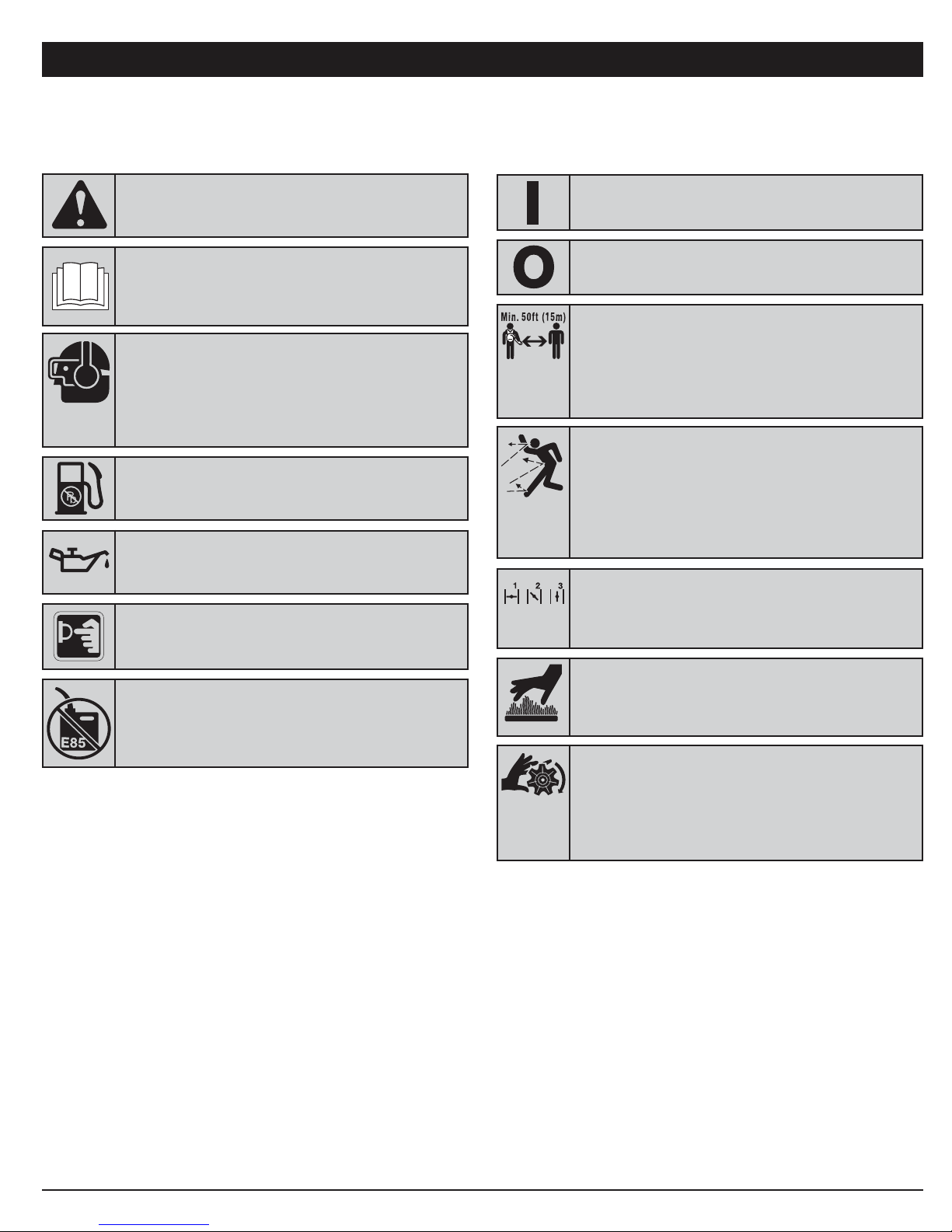
SAFETY AND INTERNATIONAL SYMBOLS
This operator's manual describes safety and international symbols and pictographs that may appear on this product.
Read the operator's manual for complete safety, assembly, operating, maintenance,` and repair information.
SYMBOL MEANING
• SAFETY ALERT SYMBOL
Indicates danger, warning or caution. May be used in
conjunction with other symbols or pictographs.
• WARNING: READ OPERATOR'S MANUAL
Read the operator’s manual(s) and follow all warnings
and safety instructions. Failure to do so can result in
serious injury to the operator and/or bystanders.
• WEAR EYE AND HEARING PROTECTION
WARNING:
cause severe eye injury and hearing loss. Wear eye
protection meeting ANSI Z87.1 standards and ear
protection when operating this unit. Use a full face
shield when needed.
• UNLEADED FUEL
Always use clean, fresh unleaded fuel.
• OIL
Refer to operator’s manual for the proper type of oil.
• PRIMER BULB
Push primer bulb, fully and slowly, 10 times.
Thrown objects and loud noise can
SYMBOL MEANING
• ON/OFF STOP CONTROL
ON / START / RUN
• ON/OFF STOP CONTROL
OFF or STOP
• KEEP BYSTANDERS AWAY
WARNING:
cause severe eye injury and hearing loss. Wear eye
protection meeting ANSI Z87.1 standards and ear
protection when operating this unit. Use a full face
shield when needed.
• THROWN OBJECTS CAN CAUSE SEVERE
INJURY
WARNING:
cause severe eye injury and hearing loss. Wear eye
protection meeting ANSI Z87.1 standards and ear
protection when operating this unit. Use a full face
shield when needed.
• CHOKE CONTROL
1. • FULL choke position
2. • PARTIAL choke position
3. • RUN choke position
Thrown objects and loud noise can
Thrown objects and loud noise can
• DO NOT USE E85 FUEL IN THIS UNIT
WARNING:
greater than 10% ethanol will likely damage this
engine and void the warranty.
It has been proven that fuel containing
• HOT SURFACE WARNING
Do not touch a hot surface. You may get burned.
These parts get extremely hot from operation. They
remain hot for a short time after the unit is turned off.
• BLOWERS – ROTATING IMPELLER
BLADES CAN CAUSE SEVERE INJURY
WARNING:
to stop before opening the vacuum door, installing or
changing tubes or bag, or before cleaning or
performing any maintenance.
Stop the engine and allow the impeller
4
TOOLS REQUIRED:
• T-20 Torx® Screwdriver
• Flathead Screwdriver
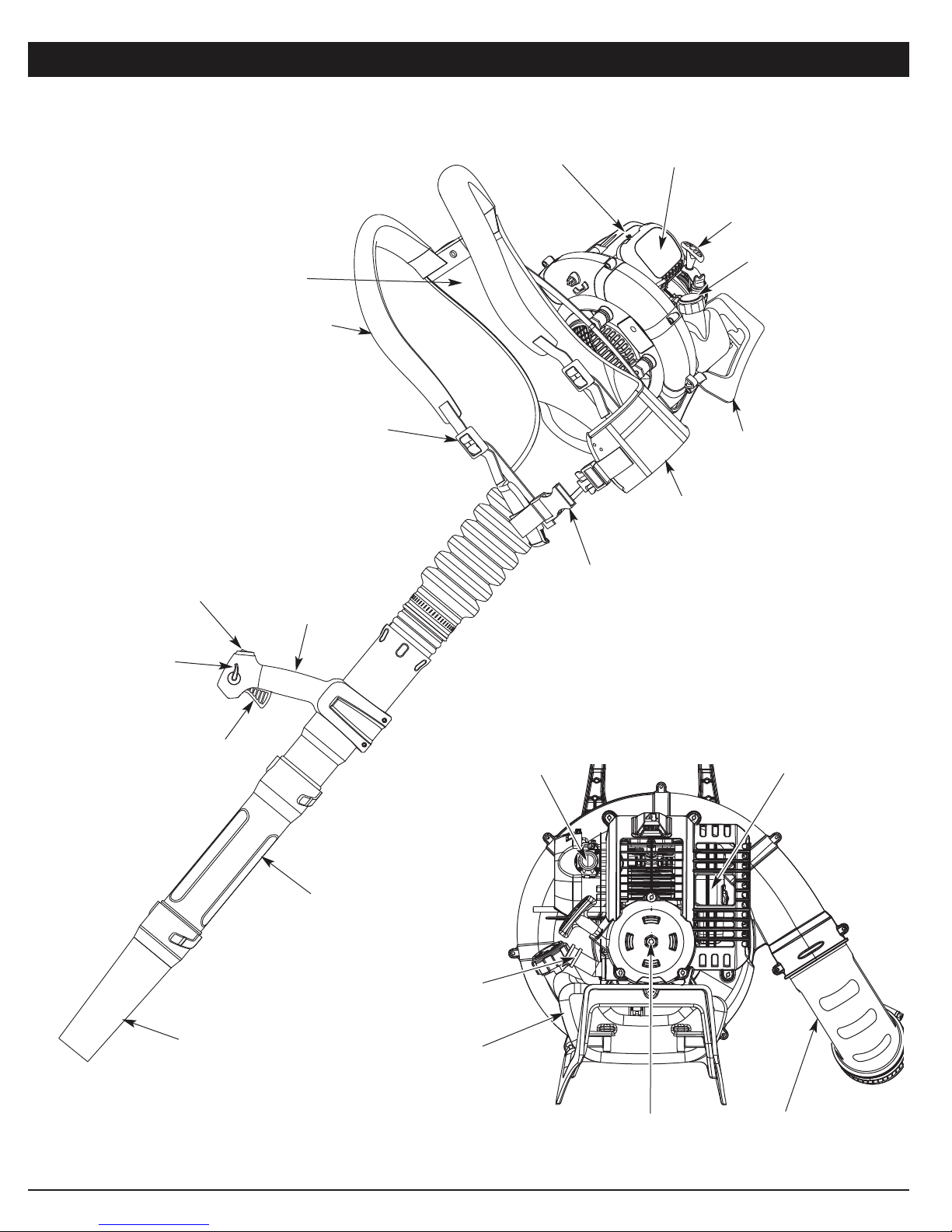
Suspension System
Shoulder Support
KNOW YOUR UNIT
Choke Lever
Air Filter Cover
Starter Rope
Handle
Gas Cap
On/Off Control
Cruise Control
Trigger
Shoulder
Support Buckle
Throttle Grip
Primer Bulb
Stand
Waist
Support
Waist
Support
Clip
Muffler
Blower
Nozzle
Tube
Oil Fill Plug
Gas Tank
Electric Start
Feature
Elbow Tube
5
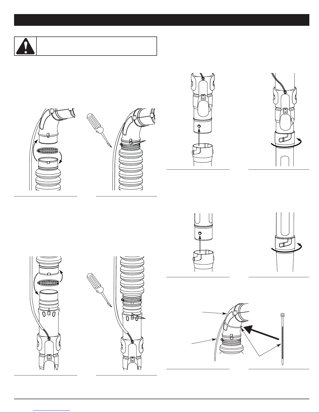
ASSEMBLY INSTRUCTIONS
ASSEMBLING THE BLOWER TUBE
WARNING:
damage to the unit, shut the unit off before removing or
installing the blower tube.
Installing the Flex Tube
1. Place a hose clamp over the end of the Flex Tube (Fig. 1A).
2. Slide the end of the Flex Tube with the clamp on it over the
elbow tube (Fig. 1B).
3. Align the bump on the Flex Tube with the bump on the elbow
tube (Fig. 1C).
4. Tighten the screw on the hose clamp to secure the Flex Tube
to the elbow tube (Fig. 1D).
To avoid serious personal injury and
C
D
B
A
Fig. 1
Installing the Upper Blower Tube
1. Place a hose clamp over the other end of the Flex Tube (Fig. 2, A).
2. Slide the end of the hose with the clamp on it over the top end
of the upper blower tube (Fig. 2, B).
3. Align the bump on the Flex Tube with the bump on the upper
blower tube (Fig. 2, C).
4. Tighten the screw on the hose clamp to secure the Flex Tube to
the upper blower tube (Fig. 2, D).
Installing the Lower Blower Tube and Nozzle
1. Align the bump slot on the end of the lower blower tube with the
bump on the bottom end of the upper blower tube (Fig. 3, A).
2. Insert the bump on the upper blower tube into the bump slot on
the lower blower tube (Fig. 3, A).
3. Twist the lower blower tube clockwise around the upper blower
tube until the upper blower tube bump locks into place (Fig. 3, B).
B
A
Fig. 3
4. Align the bump slot on the top end of the nozzle with the bump
on the bottom end of the lower blower tube (Fig. 4, A).
5. Insert the bump on the lower blower tube into the bump slot on
the nozzle (Fig. 4, A).
6. Twist the nozzle clockwise around the lower blower tube until the
nozzle bump locks into place (Fig. 4, B).
B
A
A
B
Fig. 2
6
D
Fig. 4
Secure the Throttle Cables
Place a zip tie around the elbow tube and the throttle cables, as shown
(Fig. 5). Tighten the zip tie, making sure not to crimp the cables.
Elbow Tube
C
Cables
Zip Tie
Fig. 5
ASSEMBLY INSTRUCTIONS
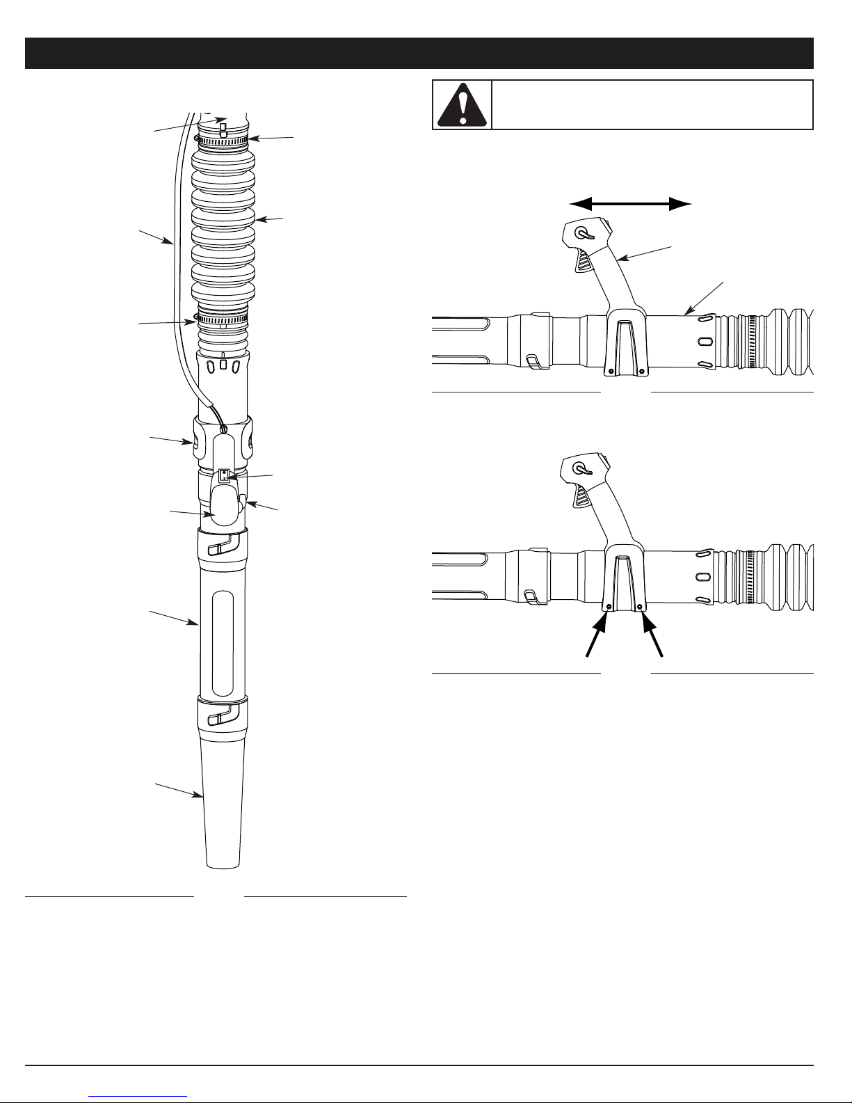
The completed blower tube should look like Figure 6.
Elbow Tube
Throttle Cables
Hose Clamp
Upper Blower Tube
On/Off Switch
Hose Clamp
Flex Tube
WARNING:
sure that the blower tubes are locked in place or firmly
installed.
Adjusting the Throttle Grip
1. Move the throttle grip to a location on the upper blower tube
that is comfortable for you (Fig. 7).
2. Using a Torx® screwdriver, tighten the two screws at the
bottom of the throttle grip (Fig. 8).
To avoid serious personal injury, make
Throttle Grip
Upper Blower Tube
Fig. 7
Throttle Grip
Lower Blower
Tube
Nozzle
Cruise Control
Fig. 8
Fig. 6
7
OIL AND FUEL INFORMATION
WARNING:
CAUSE SERIOUS PERSONAL INJURY. Check and
maintain the proper oil level in the crank case; it is
important and cannot be overemphasized. Check the oil
before each use while the engine is cold and change it
as needed. See Changing the Oil.
RECOMMENDED OIL TYPE
Using the proper type and weight of oil in the crankcase is extremely
important. Check the oil before each use and change the oil regularly.
Failure to use the correct oil, or using dirty oil, can cause premature
engine wear and failure.
Use a high-quality SAE 30 weight oil of API (American Petroleum
Institute) service class SF, SG, SH.
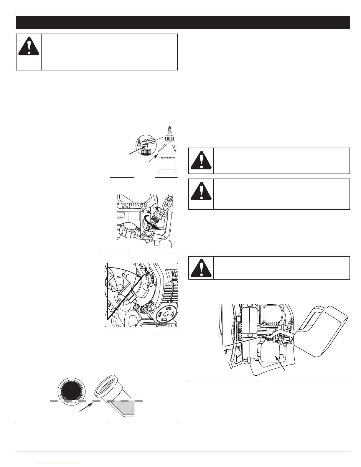
ADDING OIL TO CRANKCASE: INITIAL USE
NOTE: This unit is shipped without
oil. In order to avoid damage to the
unit, put oil in the crankcase before
you attempt to start the unit.
Your unit is supplied with one 3.04
fluid oz. (90 ml) bottle of SAE 30 SF,
SG, SH oil (Fig. 9).
NOTE: Save the bottle of oil. It can be
used to measure the correct
amount during future oil changes
(Fig. 9). See Changing the Oil.
1. Unscrew the top of the bottle
of oil and remove the paper
seal covering the opening.
Replace the top. Next, cut the
tip off the funnel spout (Fig. 9).
2. Remove the oil fill plug from
the crankcase (Fig. 10).
3. Tilt the unit backwards 30°
(Fig. 11).
4. Pour the entire bottle of oil
into the oil fill hole (Fig. 11).
NOTE: Never add oil to the fuel or
fuel tank.
5. Wipe up any oil that may have
spilled and reinstall the oil fill
plug.
Check oil before each use and
change as needed. Refer to
Checking the Oil Level.
CHECKING THE OIL LEVEL
Check the oil only when the engine is
off and cool.
1. Place the unit on its stand on a
level surface.
2. Remove the oil fill plug from the
crankcase (Fig. 10).
3. Look into the oil fill hole (Fig. 10). If the oil level comes up to
the first thread, then the oil is full (Fig. 12). If it does not, fill with
oil until it does.
OVERFILLING OIL CRANKCASE MAY
Funnel
Spout
O-Ring
Oil Fill Hole
Fill Level
Fig. 9
Oil Fill Plug
Fig. 10
30°
Fig. 11
RECOMMENDED FUEL TYPE
Old fuel is the primary reason for improper unit performance. Be
sure to use fresh, clean, unleaded gasoline.
NOTE: This is a four cycle engine. In order to avoid damage to the
unit, do not mix oil with gasoline.
Definition of Blended Fuels
Today's fuels are often a blend of gasoline and oxygenates such as
ethanol, methanol or MTBE (ether). Alcohol-blended fuel absorbs
water. As little as 1% water in the fuel can make fuel and oil
separate or form acids when stored. Use fresh fuel (less than 30
days old), when using alcohol-blended fuel.
Using Blended Fuels
If you choose to use a blended fuel, or its use is unavoidable, follow
recommended precautions:
• Always use fresh unleaded gasoline
• Use the fuel additive STA-BIL® or an equivalent
• Drain tank and run the engine dry before storing unit
Using Fuel Additives
WARNING:
outdoor area. Wipe up any spilled fuel immediately.
Avoid creating a source of ignition for spilt fuel. Do not
start the engine until fuel vapors dissipate.
WARNING:
vapors may explode. Always stop the engine and allow
it to cool before filling the fuel tank. Do not smoke while
filling the tank. Keep sparks and open flames at a
distance from the area.
The use of fuel additives, such as STA-BIL® Gas Stabilizer or an
equivalent, will inhibit corrosion and minimize the formation of gum
deposits. Using a fuel additive can keep fuel from forming harmful
deposits in the carburetor for up to six (6) months. Add 0.8 oz. (23 ml)
of fuel additive per gallon of fuel according to the instructions on the
container. NEVER add fuel additives directly to the unit's gas tank.
FUELING THE UNIT
WARNING:
from fuel spray. Never operate the unit without the fuel
cap securely in place.
1. Remove the fuel cap.
2. Place the gas container’s spout into the fill hole on the fuel tank
(Fig. 13) and fill the tank.
Gas Can
Spout
Add fuel in a clean, well ventilated
Gasoline is extremely flammable. Ignited
Remove fuel cap slowly to avoid injury
Oil Full Line
Fig. 12
8
Fuel Tank
Fig. 13
NOTE: Do not overfill the tank.
3. Wipe up any gasoline that may have spilled.
4. Reinstall the fuel cap.
5. Move the unit at least 30 ft. (9.1 m) from the fueling source and
site before starting the engine.
NOTE: Dispose of the old gasoline in accordance with federal, state
and local regulations.

STARTING/STOPPING INSTRUCTIONS
WARNING:
outdoor area. Carbon monoxide exhaust fumes can be
lethal in a confined area.
WARNING:
are in the starting position when pulling the starter rope
(Fig. 16). To avoid serious injury, the operator and unit
must be in a stable position while starting.
To avoid serious personal injury, make sure that the
blower tube is locked in place or firmly installed.
STARTING INSTRUCTIONS
1. Check the oil level in the crankcase. Refer to Checking the Oil
Level.
2. Fill the fuel tank with fresh, clean unleaded gasoline. Refer to
Fueling the Unit.
NOTE: There is no need to turn the unit on. The On/Off Control is in
the ON ( I ) position at all times.
3. Fully press and release the primer bulb 10 times, slowly. Some
amount of fuel should be visible in the primer bulb (Fig. 14). If
fuel cannot be seen in the bulb, press and release the bulb until
fuel is visible.
4. Move the choke lever to Position 1 (Fig. 14).
NOTE: The unit should be started in idle. Do not squeeze the trigger
until step 8 (Fig. 15, A).
5. Do not squeeze the trigger. Crouch in the starting position
(Fig. 16). Pull the starter rope 5 times in a controlled motion.
6. Move the choke lever to Position 2 (Fig. 14).
7. Do not squeeze the trigger. Pull the starter rope 3-5 times in a
controlled motion to start the engine.
8. Squeeze and hold the trigger, or press down the cruise control
(Fig. 15, A), and allow the engine to warm up for 30 to 60
seconds.
9. Continue to squeeze the trigger. Move the choke lever to
Position 3 (Fig. 14) and continue warming the engine for an
additional 60 seconds. During this time the unit may be used.
IF... the engine does not start, go back to step 3.
IF... the engine fails to start after a few attempts, move the choke
lever to Position 3 and pull the starter rope 3-8 times in a
controlled motion.
IF WARM... If the engine is already warm, go back to step 6.
Operate this unit only in a well- ventilated
Avoid accidental starting. Make sure you
Cruise
Control
Trigger
On/Off Switch
A
Choke Lever
Primer
Bulb
Fig. 14
SLOW
FAST
B
Fig. 15
STOPPING INSTRUCTIONS
1. Release your hand from the trigger. Allow the engine to cool
down by idling.
2. Press and hold the On/Off switch in the OFF (O) position until
the unit comes to a complete stop (Fig. 15, A).
Using the Cruise Control
1. Once the engine has started and warmed up, squeeze the
trigger to accelerate the unit as needed (Fig. 15, A).
2. For longer periods of operation and to eliminate possible finger
fatigue, move the cruise control toward the FAST position to
incrementally increase or maintain the unit’s engine speed (Fig.
15, B). When the cruise control is pressed, the trigger will
recede into the handle.
3. To decrease engine speed, move the cruise control to the SLOW
position and the trigger will return to idle position (Fig. 15, B).
Starter Rope
Fig. 16
9

STARTING/STOPPING INSTRUCTIONS
IF USING THE OPTIONAL ELECTRIC STARTER OR POWER START BIT™ ACCESSORY
WARNING:
Operate this unit only in a well- ventilated
outdoor area. Carbon monoxide exhaust fumes can be
lethal in a confined area.
WARNING:
Avoid accidental starting. Make sure you
are in the starting position when pulling the starter rope
(Fig. 16). To avoid serious injury, the operator and unit
must be in a stable position while starting.
To avoid serious personal injury, make sure that the
blower tube is locked in place or firmly installed.
NOTE- This Unit Can Use an Electric Start or Power Start Bit™
Optional Accessory!
Please refer to the Electric Starter or Power Start Bit
TM
operator’s
manual for proper use of this feature. (Items Sold Separately!
Please refer to page 15 of this manual about purchasing these
accessories.)
STARTING INSTRUCTIONS
1. Check the oil level in the crankcase. Refer to Checking the Oil
Level.
2. Fill the fuel tank with fresh, clean unleaded gasoline. Refer to
Fueling the Unit.
NOTE: There is no need to turn the unit on. The On/Off Control is in
the ON ( I ) position at all times.
3. Fully press and release the primer bulb 10 times, slowly. Some
amount of fuel should be visible in the primer bulb (Fig. 14). If
fuel cannot be seen in the bulb, press and release the bulb until
fuel is visible.
4. Move the choke lever to Position 1 (Fig. 14).
NOTE: The unit should be started in idle. Do not squeeze the
trigger until step 10 (Fig. 15, A).
5. Crouch in the starting position (Fig. 16). Insert the electric
starter or Power Start Bit™ into the back of the unit (Fig. 32).
Refer to the Operation section of the Electric Starter or Power
Start Bit
TM
operator’s manual.
6. Do not squeeze the trigger. Press and hold the electric starter
or drill’s ON (I) button for 2 seconds.
7. Move the choke lever to Position 2 (Fig. 14).
8. Do not squeeze the trigger. Press and hold the electric starter
or drill’s ON (I) button for 2-second intervals until the unit starts.
9. Remove the electric starter or drill from the unit.
10. Squeeze and hold the trigger, or press down the cruise control
(Fig. 15, A), and allow the engine to warm up for 30 to 60
seconds.
11. Continue to squeeze the trigger. Move the choke lever to
Position 3 (Fig. 14) and continue warming the engine for an
additional 60 seconds. During this time the unit may be used.
IF... the engine does not start, go back to step 3.
IF... the engine fails to start after a few attempts, place the choke
lever in Position 3 and squeeze the throttle control. Press and
hold the electric starter or drill ON (I) button for 2-second
intervals until the unit starts.
IF WARM... If the engine is already warm, go back to step 7.
STOPPING INSTRUCTIONS
1. Release your hand from the trigger. Allow the engine to cool
down by idling.
2. Press and hold the On/Off switch in the OFF (O) position until
the unit comes to a complete stop (Fig. 15, A).
Using the Cruise Control
1. Once the engine has started and warmed up, squeeze the
trigger to accelerate the unit as needed (Fig. 15, A).
2. For longer periods of operation and to eliminate possible finger
fatigue, move the cruise control toward the FAST position to
incrementally increase or maintain the unit’s engine speed (Fig.
15, B). When the cruise control is pressed, the trigger will
recede into the handle.
3. To decrease engine speed, move the cruise control to the SLOW
position and the trigger will return to idle position (Fig. 15, B).
10
OPERATING INSTRUCTIONS
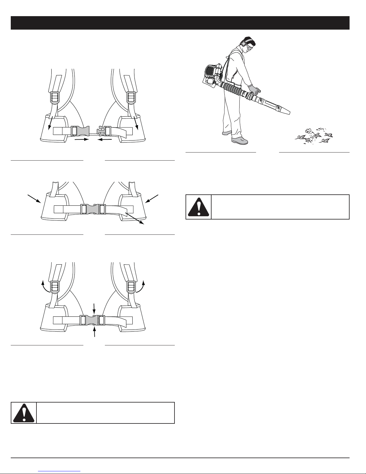
ADJUSTING THE SUSPENSION SYSTEM
1. Place the unit’s shoulder supports over the shoulders while the
unit is behind you.
2. Close the suspension system’s waist support by sliding the
waist support clips together (Fig. 17, A).
B
B
A
Fig. 17
NOTE: Make sure the weight of the unit is supported on the hips by
the waist support (Fig. 18, A).
A
A
B
Fig. 18
3. If weight is not on hips, loosen the shoulder supports (Fig. 19,
A) and pull the waist support handle (Fig. 18, B) to tighten.
Adjust until the unit’s weight rests on the hips.
A
4. Pull the shoulder support handles to tighten the shoulder
supports (Fig. 17, B).
Releasing the Suspension System
1. To release the shoulder supports, pull up on bottom tab of the
shoulder support buckles (Fig. 19, A).
2. Squeeze the top and bottom of the waist support clips to
release the waist support (Fig. 19, B).
HOLDING THE BLOWER
WARNING:
goggles or safety glasses at all times when operating this
unit. Wear a face mask or dust mask in dusty locations.
Before operating the unit, stand in the operating position (Fig. 20).
Check for the following:
• Operator is wearing proper clothing, such as boots, safety
glasses or goggles, ear/hearing protection, gloves, long pants
and long sleeve shirt.
To avoid serious personal injury, wear
B
Fig. 19
A
Fig. 20
• If the conditions are dusty, the operator is wearing a dust mask or
face mask.
• The unit is in good working condition.
• The tubes are in place and secure.
OPERATING TIPS
WARNING:
damage to the unit, make sure blower tubes are in place
before you operate the unit.
• Assure the unit is not directed at anybody or any loose debris
before starting the unit.
• Verify that the unit is in good working condition. Make sure the
tubes are in place and secure.
• Always hold the unit securely when operating.
• To reduce the risk of hearing loss associated with sound level(s),
hearing protection is required.
• Operate power equipment only at reasonable hours— not early in the
morning or late at night when people might be disturbed. Comply with
times listed in local ordinances. Usual recommendations are 9:00 am
to 5:00 pm, Monday through Saturday.
• To reduce noise levels, limit the number of pieces of equipment
used at any one time.
• To reduce noise levels, operate power blowers at the lowest
possible speed to do the job.
• Check your equipment before operation, especially the muffler,
air intakes and air filters.
• Use rakes and brooms to loosen debris before blowing.
• In dusty conditions, slightly dampen surfaces or use a mister
attachment when water is available.
• Conserve water by using power blowers instead of hoses for
many lawn and garden applications, including areas such as
screens, patios, grills, porches, and gardens.
• Watch out for children, pets, open windows or freshly washed
cars, and blow debris safely away.
• Use the full blower nozzle extension so the air stream can work
close to the ground.
• Clean up after using blowers and other equipment. Dispose of
debris appropriately.
• Use the cruise control (Fig. 15) to keep the trigger depressed
while operating to make continuous operation easier.
APPLICATIONS
1 Use the blower for trees, shrubs, flower beds and hard-to-
clean areas.
2. Use the unit around buildings and for other normal cleaning
procedures.
3. Use the blower around walls, overhangs, fences and screens.
To prevent serious personal injury or
11
MAINTENANCE AND REPAIR INSTRUCTIONS
WARNING:
maintenance or repairs with unit running. Always service and
repair a cool unit. Disconnect the spark plug wire to ensure
that the unit cannot start. See Replacing the Spark Plug.
MAINTENANCE SCHEDULE
Perform these required maintenance procedures at the frequency
stated in the table. These procedures should also be a part of any
seasonal tune-up.
NOTE: Some maintenance procedures may require special tools or
skills. If you are unsure about these procedures, take your unit to
a Troy-Bilt or other qualified service dealer.
NOTE: Maintenance, replacement, or repair of the emission control
devices and system may be performed by a Troy-Bilt or other
qualified service dealer.
NOTE: Please read the California/EPA statement that came with the
unit for a complete listing of terms and coverage for the
emissions control devices, such as the spark arrestor, muffler,
carburetor, etc.
FREQUENCY MAINTENANCE REQUIRED SEE
Every 10 hours Clean and oil air filter p 12
After 1st 10
hours
Every 40 hours
To prevent serious injury, never perform
Change oil
Check rocker arm to valve clearance
and adjust
Change oil
Check rocker arm to valve clearance
and adjust
Check spark plug condition and gap
p 12
p 13
p 12
p 13
p 14
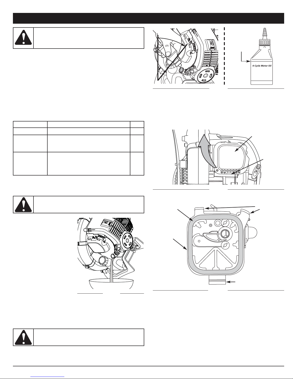
30°
Fill Level
Fig. 22
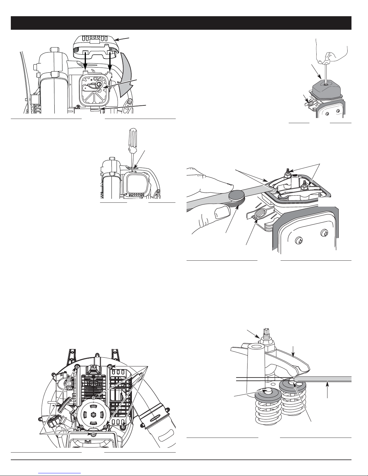
AIR FILTER MAINTENANCE
Cleaning the Air Filter
Failure to maintain your air filter properly can result in poor performance or
can cause permanent damage to your engine.
1. Open the air filter cover. Push the locking tab on the under side of
the cover inward. Then pull the air filter cover out and up. (Fig. 23).
Air Filter Cover
Locking
Ta b
CHANGING THE OIL
Change the oil while the engine is still warm. The oil will flow freely and
carry away more impurities.
WARNING: Wear gloves to prevent injury when
handling unit.
1. Remove the oil fill plug.
2. Pour the oil out of the oil fill
hole and into a container by
tipping the unit to the side
(Fig. 21). Allow ample time
for complete drainage.
3. Wipe up any oil residue on the
unit and clean up any oil that
may have spilled. Dispose of
the oil according to federal,
state and local regulations.
4. Tilt the unit backwards 30°
(Fig. 22).
5. Refill the crankcase with
3.04 fluid ounce (90 ml) of
SAE 30 SF, SG, SH oil.
b Use the bottle and spout
saved from initial use to measure the correct amount of oil. The
top of the label on the bottle measures approximately 3.04
ounces (90 ml) (Fig. 22). Check the level, See Checking the Oil
Level. If the level is low, add a small amount of oil and recheck.
Do not overfill (Fig. 22).
6. Replace the oil fill plug.
WARNING:
turn the unit off and allow it to cool before you clean or
service it.
To avoid serious personal injury, always
Fig. 21
Fig. 23
2. Remove the air filter (Fig. 24).
Air Filter
Back Plate
Locking Tab
Fig. 24
3. Wash the filter in detergent and water. Rinse the filter
thoroughly and allow it to dry.
4. Apply enough clean SAE 30 motor oil to lightly coat the filter.
5. Squeeze the filter to spread and remove excess oil.
6. Replace the filter (Fig. 24).
NOTE: If the unit is operated without the air filter, you will VOID the
warranty.
7. Reinstall the air filter cover. Position the slots on the top of the air
filter cover onto the tabs at the top of the back plate (Figs. 23 & 24).
8. Swing the cover down until the tab on the air filter backplate
snaps into place in the slot on the air filter cover (Fig. 25).
Tabs
12
MAINTENANCE AND REPAIR INSTRUCTIONS
Air Filter Cover
Air Filter
Back Plate
Ta b
Fig. 25
IDLE SPEED ADJUSTMENT
The idle speed of the engine is
adjustable. An idle adjustment screw
is between the air filter cover and the
engine starter housing (Fig. 26).
NOTE: Careless adjustments can
seriously damage your unit. An
authorized service dealer should
make carburetor adjustments.
If, after checking the fuel and
cleaning the air filter, the engine still
will not idle, adjust the idle speed
screw as follows:
1. Start the engine and let it run at
a high idle for a minute to warm up. Refer to Starting/Stopping
Instructions.
2. Release the throttle trigger and let the engine idle. If the engine
stops, insert a small Phillips screwdriver in between the air filter
cover and the engine cover (Fig. 26). Turn the idle speed screw
in, clockwise, 1/8 of a turn at a time (as needed) until the
engine idles smoothly.
Checking the fuel, cleaning the air filter, and adjusting the idle
speed should solve most engine problems. If not and all of the
following are true:
• the engine will not idle
• the engine hesitates or stalls on acceleration
• there is a loss of engine power
Have the carburetor adjusted by an authorized service dealer.
ROCKER ARM CLEARANCE
This requires disassembly of the engine. If you feel unsure or unqualified
to perform this, take the unit to an authorized service center.
• The engine must be cold when checking or adjusting the valve
clearance.
• This task should be performed inside, in a clean, dust free area.
1. Remove the seven (7) screws on the back of the engine cover
with a Flat-head or T-25 Torx® screwdriver (Fig. 27).
Fig. 26
Idle
Adjustment
Screw
2. Disconnect the spark plug wire.
3. Clean dirt from around the spark
plug. Remove the spark plug from
the cylinder head by turning a 5/8 in.
socket counterclockwise.
4. Remove the engine cover (Fig. 27).
5. Clean dirt from around the rocker
arm cover. Remove the screw
holding the rocker arm cover with a
large flat blade screwdriver or Torx®
T-25 bit (Fig. 28). Remove the rocker
arm cover and gasket.
6. Pull the starter rope slowly to bring
the piston to the top of its travel,
(known as top dead center). Check
that:
• The piston is at the top of its travel while looking in the spark
plug hole (Fig. 29).
• Both rocker arms move freely, and both valves are closed.
If these statements are not true, repeat this step.
Rocker Arms
Feeler Gauge
Spark Plug Hole
7. Slide the feeler gauge between the rocker arm and the valve return
spring. Measure the clearance between the valve stem and rocker
arm (Fig. 29). Measure both the intake and exhaust valves.
The recommended clearance for both intake and exhaust is .003 –
.006 in. (.076 – 0.152 mm). Use a standard automotive .005 in.
(0.127 mm) feeler gauge. The feeler gauge should slide between the
rocker arm and valve stem with a slight amount of resistance,
without binding. See Figures 29 and 30.
Adjusting Nut
INTAKE
Fig. 29
Rocker Arm
Rocker
Arm
Cover
Spark
Plug
Hole
Fig. 28
Adjusting Nuts
EXHAUST
Remove
Screws
Fig. 27
Remove
Screws
.003–.006 in.
(.076–.152 mm)
Intake Valve
Stem
Feeler Gauge
Valve Stem
Fig. 30
13
MAINTENANCE AND REPAIR INSTRUCTIONS
CLEANING AND STORAGE
8. If the clearance is not within specification:
a. Turn the adjusting nut (Fig. 30) using a 5/16 inch (8 mm) wrench
or nut driver.
• To increase clearance, turn the adjusting nut counterclockwise.
• To decrease clearance, turn the adjusting nut clockwise.
b. Recheck both clearances, and adjust as necessary.
9. Reinstall the rocker arm cover using a new gasket. Torque the
screw to 20–30 in•lb (2.2–3.4 N•m).
10. Check the spark plug and reinstall. See Replacing the Spark Plug.
11. Replace the spark plug wire.
12. Reinstall the engine cover. Check alignment of the cover before
tightening the screws. Tighten screws.
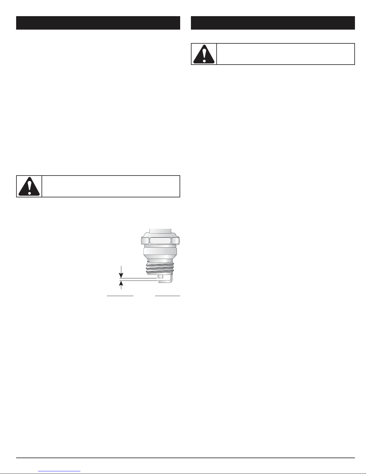
REPLACING THE SPARK PLUG
Use a replacement part number 753-05784 or Champion® RDZ4H
spark plug. The correct air gap is 0.025 in. (0.635 mm).
1. Stop the engine and allow it to cool. Remove the seven (7)
screws on the back of the engine cover with a Flat-head or T25 Torx® screwdriver (Fig. 27).
2. Grasp the plug wire firmly and pull the cap from the spark plug.
3. Clean dirt from around the spark plug. Remove the spark plug
from the cylinder head by turning a 5/8 in. socket
counterclockwise.
CAUTION:
electrodes. Grit in the engine could damage the cylinder.
4. Replace cracked, fouled or dirty spark plug. Set the air gap at
0.025 in. (0.635 mm) using a feeler gauge (Fig. 31).
5. Install a correctly-gapped spark plug in the cylinder head. Turn
the 5/8 in. socket clockwise until snug.
If using a torque wrench torque to:
110-120 in.•lb. (12.3-13.5 N•m)
Do not over tighten.
Do not sand blast, scrape or clean
CLEANING
WARNING:
turn your unit off and allow it to cool before you clean or
service it.
Use a small brush to clean off the outside of the unit. Do not use strong
detergents. Household cleaners that contain aromatic oils such as pine
and lemon, and solvents such as kerosene, can damage plastic
housing or handle. Wipe off any moisture with a soft cloth.
STORAGE
• Never store the unit with fuel in the tank where fumes may reach
an open flame or spark.
• Allow the engine to cool before storing.
• Lock up the unit to prevent unauthorized use or damage.
• Store the unit in a dry, well-ventilated area.
• Store the unit out of the reach of children.
Long Term Storage
1. Drain all gasoline from the gas tank into a container. Do not use gas
that has been stored for more than 30 days. Dispose of the old
gasoline in accordance with federal, state and local regulations.
2. Start the engine and allow it to run until it stalls. This ensures
that all gasoline has been drained from the carburetor.
3. Allow the engine to cool. Remove the seven (7) screws on the
back of the engine cover with a Flat-head or T-25 Torx®
screwdriver. Remove the spark plug and put 5 drops of high
quality motor oil into the cylinder. Pull the starter rope slowly to
distribute the oil. Reinstall the spark plug.
NOTE: Remove the spark plug and drain all of the oil from the
cylinder before attempting to start the unit after storage.
4. Change the oil, referring to Changing the Oil. Dispose of the
old oil in accordance with federal, state and local regulations.
5. Thoroughly clean the unit and inspect for any loose or
damaged parts. Repair or replace damaged parts and tighten
loose screws, nuts or bolts. The unit is ready for storage.
To avoid serious personal injury, always
0.025 in.
(0.635 mm)
Fig. 31
14
OPTIONAL ACCESSORY
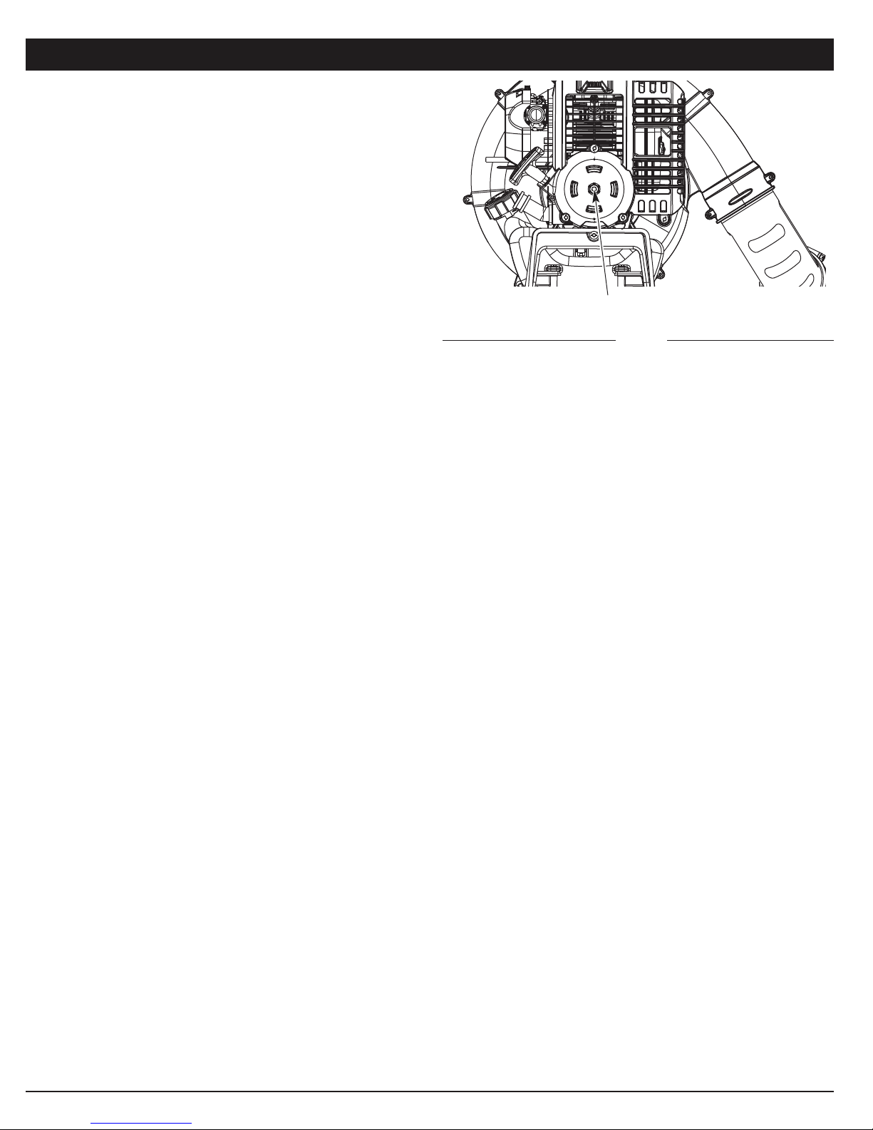
ELECTRIC STARTER AND POWER START BIT™ FEATURES
This unit is designed to be started with an optional electric starter or
Power Start Bit™ that are sold separately. If choosing to start the
unit using one of these features or have questions, please contact
your local retailer or call 1-800-828-5500 in the U.S (1-800-668-1238
in Canada) for more information and purchasing. You may also go to
www.troybilt.com or www.troybilt.ca.
Electric Start Feature
Fig. 32
15

TROUBLESHOOTING
CAUSE ACTION
ENGINE WILL NOT START
Empty fuel tank Fill fuel tank with fuel
Primer bulb wasn't pressed enough Press primer bulb fully and slowly 10 times
Old fuel (over 30 days) Drain fuel tank and add fresh fuel
Fouled spark plug Replace or clean the spark plug
ENGINE WILL NOT IDLE
Air filter is plugged Replace or clean the air filter
Old fuel (over 30 days) Drain fuel tank and add fresh fuel
Improper idle speed Adjust according to the Idle Speed Adjustment section
ENGINE WILL NOT ACCELERATE
Old fuel (over 30 days) Drain fuel tank and add fresh fuel
Dirty air filter Clean or replace the air filter
ENGINE LACKS POWER OR STALLS
Old fuel (over 30 days) Drain fuel tank and add fresh fuel
Fouled spark plug Replace or clean the spark plug
If further assistance is required, contact your authorized service dealer.
16

SPECIFICATIONS*
Engine Type . . . . . . . . . . . . . . . . . . . . . . . . . . . . . . . . . . . . . . . . . . . . . . . . . . . . . . . . . . . . . . . . . . . . . . . . . . . . . . . . . . . . . . . Air-Cooled, 4-Cycle
3
Displacement . . . . . . . . . . . . . . . . . . . . . . . . . . . . . . . . . . . . . . . . . . . . . . . . . . . . . . . . . . . . . . . . . . . . . . . . . . . . . . . . . . . . . . . . . 1.95 in.
(32 cc)
Operating RPM . . . . . . . . . . . . . . . . . . . . . . . . . . . . . . . . . . . . . . . . . . . . . . . . . . . . . . . . . . . . . . . . . . . . . . . . . . . . . . . . . . . . . . 6,500–7,500 rpm
Idle Speed RPM . . . . . . . . . . . . . . . . . . . . . . . . . . . . . . . . . . . . . . . . . . . . . . . . . . . . . . . . . . . . . . . . . . . . . . . . . . . . . . . . . . . . . 3,800–4,400 rpm
Blower Velocity . . . . . . . . . . . . . . . . . . . . . . . . . . . . . . . . . . . . . . . . . . . . . . . . . . . . . . . . . . . . . . . . . . . . . . . . . . . . . . . . up to 150 mph (240 kmh)
Blower Air Output . . . . . . . . . . . . . . . . . . . . . . . . . . . . . . . . . . . . . . . . . . . . . . . . . . . . . . . . . . . . . . . . . . . . . . . . . . . . . up to 500 cfm (14.2 cmm)
Valve clearance . . . . . . . . . . . . . . . . . . . . . . . . . . . . . . . . . . . . . . . . . . . . . . . . . . . . . . . . . . . . . . . . . . . . . . . . 0.003–0.006 in. (0.076–0.152 mm)
Spark Plug Gap . . . . . . . . . . . . . . . . . . . . . . . . . . . . . . . . . . . . . . . . . . . . . . . . . . . . . . . . . . . . . . . . . . . . . . . . . . . . . . . . . . 0.025 inch (0.635 mm)
Lubrication . . . . . . . . . . . . . . . . . . . . . . . . . . . . . . . . . . . . . . . . . . . . . . . . . . . . . . . . . . . . . . . . . . . . . . . . . . . . . . . . . . . . . . . . . . . . . . . SAE 30 Oil
Crankcase Oil Capacity . . . . . . . . . . . . . . . . . . . . . . . . . . . . . . . . . . . . . . . . . . . . . . . . . . . . . . . . . . . . . . . . . . . . . . . . . . . . . . . . . . 3.04 oz (90 ml)
Fuel . . . . . . . . . . . . . . . . . . . . . . . . . . . . . . . . . . . . . . . . . . . . . . . . . . . . . . . . . . . . . . . . . . . . . . . . . . . . . . . . . . . . . . . . . . . . . . . . . . . . . Unleaded
Fuel Tank Capacity . . . . . . . . . . . . . . . . . . . . . . . . . . . . . . . . . . . . . . . . . . . . . . . . . . . . . . . . . . . . . . . . . . . . . . . . . . . . . . . . . . . . . . 26 oz (768 ml)
* All specifications are based on the latest product information available at the time of printing. We reserve the right to make changes at any
time without notice.
17
 Loading...