


Traulsen UR30WT, UR48WT, UR30LT, UR48DT, UC27HT User Manual
...
Quality Refrigeration
OWNER’SMANUAL
Instructions for the installation, operation
and maintenance of all Traulsen Spacesaver Models:
Refrigerator Models: UR30HT, UR48HT, UC27HT
Freezer Model: UR30LT
Refrigerator/Freezer Model: UR48DT
Wine Cabinets: UR30WT, UR48WT, UC27WT
This Traulsen unit is built to our highest quality standards. We build our refrigerators, freezers and heated cabinets this way as a matter of pride. This philosophy has made Traulsen the leader in commercial refrigeration since 1938. We thank you for your choice and confidence in Traulsen equipment and we know you will receive many years of utility from this equipment.
All Traulsen units are placed on a permanent record file with the service department. In the event of any future questions you may have, please refer to the model and serial number found on the name tag affixed to the unit. Should you need service, however, call us on our toll free number, 800-825-8220 between 7:30 am and 4:30 pm CST, Monday thru Friday. It is our pleasure to help and assist you in every possible way.
INSTALLER
COMPLETE THE FOLLOWING INFORMATION PRIOR TO UNIT INSTALLATION
INITIAL START DATE: |
SERIAL NO. |
MODEL TYPE:
COMPANY/INDIVIDUAL NAME:
INSTALLER:
FORM NUMBER TR35749 REV. 5/03 |
P/N 375-60177-00 |
TABLE OF CONTENTS
I. The Serial Tag |
Page 1 |
V. Operation |
|
II. Receipt Inspection |
Page 2 |
a-Adjusting The Temperature |
Page 6 |
III. Installation |
|
b-Automatic Defrost |
Page 6 |
a-Location |
Page 2 |
|
|
b-Packaging |
Page 2 |
VI. Care & Maintenance |
|
c-Installing Legs or Casters |
Page 2 |
a-Cleaning The Condenser |
Page 6 |
d-Shelf Pins |
Page 3 |
b-Hinge Replacement |
Page 6 |
e-Installing The Condensate Evaporator |
Page 3 |
c-Replacing The Gaskets |
Page 6 |
f-Remote Installation |
Page 3 |
d-Cleaning The Exterior |
Page 7 |
g-Cord & Plug |
Page 3 |
e-Cleaning The Interior |
Page 7 |
h-Power Supply |
Page 3 |
f-Changing The Interior Light |
Page 7 |
i-Wiring Diagram |
Page 3 |
VII. Misc. Operations |
|
j-Clearance |
Page 3 |
a-Adjusting The Shelves |
Page 7 |
k-Built-In Installation |
Page 4 |
b-Removing The Drawer Pans |
Page 7 |
l-Electric Outlet Installation |
Page 5 |
c-Removing The Drawers |
Page 7 |
IV. Miscellaneous Product Features |
|
VIII. Other |
|
a-Solar Digital Thermometer |
Page 5 |
a-Service Information |
Page 7 |
b-Light Switches |
Page 5 |
b-Spare Parts |
Page 8 |
c-Defogger Control |
Page 5 |
c-Warranty Registration |
Page 8 |
|
|
IX. Trouble Shooting Guide |
Page 8 |
|
|
X. Warranty Information |
Page 9 |
|
|
XI. Index |
Page 10 |
|
|
|
|
I. THE SERIAL TAG |
|
FORT WORTH, TX. |
|
The serial tag is a permanently affixed sticker on |
|
|
|
which is recorded vital electrical and refrigeration data |
||
|
|
|
|
|
|
|
|
|
|
SERIAL |
MODEL |
|
|
about your Traulsen product, as well as the model |
VOLTS |
Hz |
PH |
|
and serial number. This tag is located in the upper |
|
|
|
|
right interior compartment on all Spacesaver reach- |
TOTAL CURRENT |
|
AMPS |
|
in refrigerator, freezer and undercounter models. |
MINIMUM CIRCUIT |
|
AMPS |
|
|
MAXIMUM OVERCURRENT PROTECTION |
AMPS |
|
||
LIGHTS |
|
WATTS |
|
READING THE SERIAL TAG |
HEATERS |
|
AMPS |
|
|
|
|
|
||
REFRIGERANT |
|
TYPE |
OZ |
• Serial = The permanent ID# of your Traulsen |
DESIGN PRESSURE |
|
HIGH |
LOW |
• Model = The model # of your Traulsen |
|
|
|
|
• Volts = Voltage |
REFRIGERANT |
|
TYPE |
OZ |
• Hz = Cycle |
DESIGN PRESSURE |
|
HIGH |
LOW |
• PH = Phase |
|
|
370-60294-00 REV (A) |
|
• Total Current = Maximum amp draw |
|
|
|
|
• Minimum Circuit = Minimum circuit ampacity |
|
|
|
|
• Lights = Light wattage |
|
|
|
|
• Heaters = Not applicable for Spacesaver models |
|
|
|
|
• Refrigerant = Refrigerant type used |
|
|
|
|
• Design Pressure = High & low side operating |
|
|
|
|
pressures and refrigerant charge |
|
|
|
|
• Agency Labels = Designates agency listings |
-1-
II. RECEIPT INSPECTION |
III. INSTALLATION (continued) |
All Traulsen products are factory tested for performance and are free from defects when shipped. The utmost care has been taken in crating this product to protect against damage in transit. All interior fittings have been carefully secured and the legs or casters and bottom mounted condensate evaporator are boxed and strapped inside to prevent damage. If the unit is equipped with optional locks the door keys will be attached to the handle with a nylon strip. The handle is protected by an easily removable nylon netting.
You should carefully inspect your Traulsen unit for damage during delivery. If damage is detected, you should save all the crating materials and make note on the carrier’s Bill Of Lading describing this. A freight claim should be filed immediately. If damage is subsequently noted during or immediately after installation, contact the respective carrier and file a freight claim. Under no condition may a damaged unit be returned to Traulsen & Co. without first obtaining written permission (return authorization).
III.INSTALLATION
III.a - LOCATION:
Select a proper location for your Traulsen Spacesaver unit, away from extreme heat or cold. Allow enough clearance between the unit and the side wall so that the door (s) may open a minimum of 90°.
III. b - PACKAGING:
All Traulsen Spacesaver units are shipped from the factory bolted to a sturdy wooden pallet and packaged in a durable cardboard container. The carton is attached to the wooden skid with the use of large staples. These should first be removed to avoid scratching the unit when lifting off the crate.
To remove the wooden pallet, first if at all possible, we suggest that the cabinet remain bolted to the pallet during all transportation to the point of final installation. The bolts can then be removed with a 3/4” socket wrench. Avoid laying the unit on its front, side or back for removal of the pallet.
All exterior metal surfaces are protected from scratching during manufacturing and shipping by a plastic covering. This should be removed prior to installation.
NOTE: Traulsen does not recommend laying the unit down on its front, side or back. However, if you must please be certain to allow the unit to remain in an upright position afterwards for 24 hours before plugging it in so that the compressor oils and refrigerant may settle.
-2-
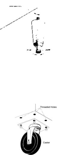
III. c - INSTALLING LEGS OR CASTERS:
6” high stainless steel legs are supplied standard for all Traulsen Spacesaver units. Casters in lieu of legs are available as an optional accessory for the same models. These are shipped from the factory packed inside a cardboard box which is strapped to one of the shelves. Remove the nylon strap and open the box, it should contain either four (4) legs or four (4) casters and sixteen (16) bolts.
WARNING: THE CABINET MUST BE BLOCKED AND STABLE BEFORE INSTALLING LEGS OR CASTERS.
To install the legs or casters, first raise and block the unit a minimum of 7” from the floor. For installing legs, thread the legs into the threaded holes on the bottom of the cabinet (see figure 1). Be certain that all legs are tightly secured (legs and casters should be tightened to 300 inch/pounds, max). When the unit is set in its final position, it is important for proper operation that the unit be level. The legs are adjustable for this purpose, turn the bottom of the leg counterclockwise to raise it, clockwise to lower it. Level the unit from front to back as well as side to side in this manner, using a level placed in the bottom of the cabinet.
Fig. 1
Please note that Traulsen Spacesaver units are not designed to be moved while on legs. If the unit requires moving, a pallet jack or forklift should be used to prevent damage. For installing casters, the casters are “plate” type, and require the use of four (4) bolts each to secure them firmly to the cabinet bottom at each corner (see figure 2). The caster bolts are tightened using a 1/2” socket wrench.
Figure 2
III. INSTALLATION (continued)
III. d - SHELF PINS:
The unit is supplied with shelves and shelf pins installed. Check all shelf pins to assure they are tightened down as they may have come loose during shipping. Rotate the pins clockwise until they are secured against the side of the cabinet.
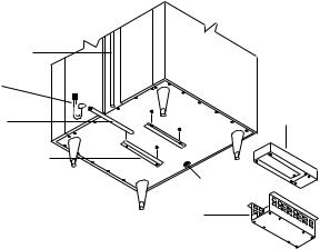
III. e - INSTALLING THE CONDENSATE EVAPORATOR: A bottom-mounted electric condensate evaporator is normally supplied on all self-contained models. This is shipped in a cardboard carton secured to the cabinet interior, and must be installed prior to use.
To install a bottom-mounted electric condensate evaporator (see figure 3).
After the cabinet has been uncrated and the legs/casters attached, locate the four (4) holes on the exterior bottom towards the rear of the cabinet. Then, using the four (4) screws provided, attach the mounting rails to the cabinet bottom (the end flange is to be up and be facing towards the cabinet rear). Next, place the heater into the heater bracket (note the enclosed springs are only to be used when the heater is placed on the floor). Slide heater and bracket into the mounting rails. Plug the supplied cord into both the heater on one end, and the electrical outlet, provided on the cabinet exterior bottom towards the front, on the other. Screw the “U-Trap” (UR30LT only) or 90 degree elbow joint (all other Spacesaver models) into the drain line located on the rear of the cabinet and then screw the drain extension into the U-Trap or elbow joint.
|
Drain |
|
|
Line |
|
U-Trap |
|
|
Drain |
Electric |
|
Heater |
||
Extension |
||
|
10-32 x 3/8 Screw (4)
Mounting Rails
BMCE
Receptacle
Heater
Bracket
Figure 3
A remote model is normally configured for condensate to be run to a floor drain unless purchased with a condensate evaporator. The installer is responsible for making the required extension to the floor drain in accordance with good practice and local regulations.
The bottom mounted electric condensate evaporator of your Traulsen Spacesaver should be cleaned occasionally to keep it clear of dirt and debris.
-3-
III. f - REMOTE INSTALLATION:
Remote models are supplied without compressors, solenoid valves, etc. The correct voltage, amp listing, refrigerant and BTU’s are listed on the unit’s serial tag. It is the responsibility of the installer to specify and supply the correct size compressor(s) based upon this information and on-site requirements. Refrigerant line installation must be done in adhering to good practice and local regulations. See section “III. e” for information concerning condensate removal for remote models.
III. g - CORD & PLUG:
Most self-contained models are supplied with a cord & plug attached. It is shipped coiled at the top of the cabinet, secured by a nylon strip. For your safety and protection, all units supplied with a cord and plug include a special three-prong grounding plug on the service cord. Select only a dedicated electrical outlet with grounding plug for power source. NOTE: Do not under any circumstances, cut or remove the round grounding prong from the plug, or use an extension cord.
III. h - POWER SUPPLY:
It is recommended that the supply voltage be checked prior to connection to be certain that proper voltage for the cabinet wiring is available (refer to the serial tag to determine correct unit voltage). Make connections in accordance with local electrical codes. Use qualified electricians.
Use of a separate, dedicated circuit is recommended. Size wiring to handle indicated load and provide necessary overcurrent protector in circuit.
III. i - WIRING DIAGRAM:
Refer to the wiring diagram for any service work performed on the unit. Should you require one, please contact Traulsen Service at (800) 825-8220, and provide the model and serial number of the unit involved.
III. j - CLEARANCE:
In order to assure optimum performance, the condensing unit of your Traulsen unit MUST have an adequate supply of air for cooling purposes. Therefore, the operating location must either have a minimum of 12” clearance overhead of the condensing unit or allow for unrestricted air flow at the back of the unit. Clearance of at least 12” above is required in order to perform certain maintenance tasks.
 Loading...