


Quality Refrigeration
OWNER’S MANUAL
Instructions for the installation, operation and maintenance of Traulsen:
TS Series Pizza/Salad/Sandwich Prep Tables TS048HT, TS066HT, TS072HT & TS090HT
This Traulsen unit is built to our highest quality standards. We build our refrigerators this way as a matter of pride. This philosophy has made Traulsen the leader in commercial refrigeration since 1938. We thank you for your choice and confidence in Traulsen equipment and we know you will receive many years of utility from this equipment.
All Traulsen units are placed on a permanent record file with the service department. In the event of any future questions you may have, please refer to the model and serial number found on the name tag affixed to the unit. Should you need service, call us on our toll free number, 800-825-8220 between 7:30 am - 4:30 pm CST, Monday thru Friday. You may also log onto www.traulsen.com for further information. It is our pleasure to help and assist you in every possible way.
INSTALLER
COMPLETE THE FOLLOWING INFORMATION PRIOR TO UNIT INSTALLATION
INITIAL START DATE: |
|
SERIAL NO. |
MODEL TYPE:
COMPANY/INDIVIDUAL NAME:
INSTALLER:
FORM NUMBER TR35921 REV. 11/10 |
P/N 375-60308-00 |
TABLE OF CONTENTS
I. THE SERIAL TAG |
Page 1 |
e-Enter The Service Access |
Page 7 |
II. RECEIPT INSPECTION |
Page 2 |
|
|
III. OPERTIONAL GUIDELINES |
Page 2 |
f-Customer/Service Parameters |
Page 7 |
IV. INSTALLATION |
|
g-Adjusting Thermostat Set Point |
Page 8 |
a-Location |
Page 2 |
h-Adjusting Thermostat Set Point Differential |
Page 8 |
b-Packaging |
Page 2 |
i-Changing The Temperature Scale |
Page 8 |
c-Installing/Adjusting Legs orCasters |
Page 2 |
j-Setting The 24-Hour Clock |
Page 8 |
d-Doors |
Page 2 |
k-Setting The Date |
Page 9 |
e-Installing Optional Drawers |
Page 2 |
l-Setting Daylight Savings Time |
Page 9 |
f-Cord & Plug |
Page 2 |
m-Starting A Manual Defrost Cycle |
Page 10 |
g-Power Supply |
Page 3 |
n-Setting Defrost Lockouts |
Page 10 |
V. DAILY OPERATION |
|
o-Adjusting The Room Temperature Offset |
Page 11 |
a-Pans |
Page 3 |
p-Viewing Sensor Temperatures |
Page 11 |
b-Setting Up The Rail |
Page 3 |
VIII. WIRING DIAGRAM |
Page 12 |
c-Closing Down The Rail At Night |
Page 3 |
|
|
d-Defrost |
Page 3 |
IX. TROUBLE SHOOTING GUIDE |
Page 13 |
VI. CARE & MAINTENANCE |
|
X. SERVICE ASSISTANCE |
|
a-Cleaning The Condenser/Filter |
Page 4 |
a-Service Information |
Page 14 |
b-Replacing The Gaskets |
Page 4 |
b-Service Support Information |
Page 14 |
c-Cleaning The Cabinet Surfaces |
Page 4 |
c-Warranty Registration |
Page 14 |
d-Cleaning The Rail Area |
Page 4 |
XI. WARRANTIES |
Page 15 |
VII. MICROPROCESSOR CONTROL |
|
XII. SERVICE PARTS LIST |
Page 16 |
a-Control Features |
Page 5 |
|
|
b-Alarm Explanations |
Page 6 |
|
|
c-Control Panel Diagram |
Page 7 |
|
|
d-Notes To The User |
Page 7 |
|
|
|
|
|
|
I. THE SERIAL TAG
I. a - SERIAL TAG:
The serial tag is a permanently affixed label on which is recorded vital electrical and refrigeration data about your Traulsen product, as well as the model and serial number. This tag is located in the right interior compartment on all standard TS Series models.
READING THE SERIAL TAG
•Serial = The permanent ID# of your Traulsen unit
•Model = The model # of your Traulsen unit
•Volts = Voltage
•Hz = Cycle
•PH = Phase
•Total Current = Maximum amp draw
•Minimum Circuit = Minimum circuit ampacity
•Lights = Light wattage
•Heaters = Heater amperage (Hot Food units only)
•Refrigerant = Refrigerant type used and refrigerant charge
•Design Pressure = High & low side operating pressures
•Agency Labels = Designates agency listings
FORT WORTH, TX.
SERIAL |
MODEL |
|
VOLTS |
Hz |
PH |
TOTAL CURRENT |
AMPS |
|
MINIMUM CIRCUIT |
AMPS |
|
MAXIMUM OVERCURRENT PROTECTION |
AMPS |
|
LIGHTS |
WATTS |
|
HEATERS |
AMPS |
|
REFRIGERANT |
TYPE |
OZ |
DESIGN PRESSURE |
HIGH |
LOW |
REFRIGERANT |
TYPE |
OZ |
DESIGN PRESSURE |
HIGH |
LOW |
370-60294-00 REV (A)
COMMERCIAL REFRIGERATION
-1-
II. RECEIPT INSPECTION
II. a - RECEIPT INSPECTION:
All Traulsen products are factory tested for performance and are free from defects when shipped. The utmost care has been taken in crating this product to protect against damage in transit.
You should carefully inspect your unit for damage during delivery. If damage is detected, you should save all the crating materials and make note on the carrier’s Bill Of Lading describing the damage. A freight claim should be filed immediately. If damage is subsequently noted during or immediately after installation, contact our customer care team to file a freight claim. There is a fifteen (15) day limit to file freight damage with the carrier. Under no condition may a damaged unit be returned to Traulsen without first obtaining written permission
(return authorization). You may contact Hobart/Traulsen customer care at 800-333-7447 to request a return or file a claim.
III. OPERATIONAL GUIDELINES
III. a - OPERATIONAL GUIDELINES:
Follow these simple guidelines for proper TS Series Operation.
1.Keep the condenser clean. Don’t obstruct airflow.
2.Use up to 6” deep stainless steel or aluminum pans.
3.All pan spaces should be filled any time the unit is running, even if some pans are empty.
4.Keep the room temperature at 860F (300C) or less.
5.Do not allow air drafts (such as heat, A/C or ventilation) to blow on or over the rail area. This will disrupt the air blanket over the product area, resulting in poor holding temperatures.
6.Rail covers should be closed over the rail as much as possible.
7.Product should be loaded into the rail at a maximum temperature of 360F. The TS Series unit was not designed to chill warm product, but to hold refrigerated product at a safe temperature.
8.Keep area around the evaporator fans clear.
IV. INSTALLATION
IV. a - LOCATION:
Select a proper location for your unit, away from extreme heat or cold. Allow enough clearance between the unit and the side wall in order to make use of the door stay open feature at 1200 (self-closing feature operates up to 900). The door(s) must be able to open a minimum of
900 in order to make use of the maximum clear door width.
IV. b - PACKAGING:
Your Traulsen unit is shipped from the factory bolted to a sturdy wooden pallet in stretch wrapped material and wood crate.
Most exterior stainless steel surfaces have a protective vinyl covering to prevent scratching during manufacturing, shipping and installation.
After the unit is installed in place of application peel, remove and discard the covering from all surfaces.
IV. INSTALLATION (CONTINUED)
IV. b - PACKAGING (continued):
To remove the wooden pallet, first if at all possible, we suggest that the cabinet remain bolted to the pallet during all transportation to the point of final installation. The bolts can then be removed with a 1/2” socket wrench. Avoid laying the unit on its front, side or back for removal of the pallet.
NOTE: Traulsen does not recommend laying the unit on its front, side or back. If you must, please allow the unit to remain in an upright position for 24 hours before plugging it in so that the compressor oils and refriger-
ant may settle.
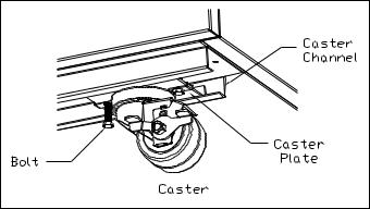
IV. c - INSTALLING/ADJUSTING LEGS OR CASTERS:
To install legs or casters, slide leg or caster into the caster channel from the side of the unit without the refrigeration system.
To adjust the legs or casters, loosen the two bolts and move leg or caster to desired location, spacing between leg or caster not to exceed 48 inches. Leg or caster on each end of the unit can not exceed 8 inches from the end of the cabinet.
NOTE: Traulsen recommends to position legs or casters under the mullion when possible.
IV. d - DOORS:
Your Traulsen TS Series model door(s) are field re-hingeable. If re-hinging is required, please contact our in-house service department at 800-825-8220 for re-hinging instructions.
IV. e - INSTALLING OPTIONAL DRAWERS:
Doors are supplied standard on all TS Series models. However, we have engineered our refrigerator models with a drop-in feature that allows you to easily convert door(s) into two 6” deep drawers or three 4” deep drawers.
The door(s) on the refrigerator models can easily be converted to drawers in the field. To begin the process, open the door to its maximum position. Support the non-hinged end of the door so minimum movement occurs. When the bolts from the lower hinge plate are removed, remove the lower hinge plate and then the door from the top hinge bracket plate and then the door from the top hinge bracket. The hinge plate pin and plastic bushing will remain in the top hinge plate.
NOTE: The lower hinge plate is under spring tension.
-2-

IV. INSTALLATION (continued) |
IV. INSTALLATION (continued) |
IV. e - INSTALLING OPTIONAL DRAWERS (continued):
Once the door(s) have been removed, Insert drawer frame as shown below.
NOTE: Undercounter model drawings shown below.
Once the drawer frame has been inserted, the drawer frame module can be installed by tighting the black front and back clamping knobs (2 of each) located on the cross rail locks and liner locks. Slide the front cross rail locks towards the center of the drawer frame module and allow the liner locks to drop down from the top of the liner. Insert the door frame module push towards the back of the unit. The entire frame assembly is now installed and ready for use.
NOTE: Repeat process for multiple drawer inserts.
Front Clamping Knobs
Front Cross Rail Locks
Back Clamping
Knobs
IV. f - CORD & PLUG:
All self-contained models are shipped standard with a NEMA 5-15P plug and 9 foot cord . Select only a dedicated electrical outlet for power source.
NOTE: Do not under any circumstances, cut or remove the round grounding prong from the plug, or use an extension cord.
IV. g - POWER SUPPLY:
The supply voltage should be checked prior to connection to be certain that proper voltage for the cabinet wiring is available (refer to the serial tag to determine correct unit voltage,see page 1). Make connections in accordance with local electrical codes. Use qualified electricians.
Use of a separate, dedicated circuit is required. Size wiring to handle indicated load and provide necessary over current protector in circuit
(see amperage requirements on the unit’s serial tag).
V. DAILY OPERATION
V. a - PANS:
Standard TS Series models are designed to operate with full, half or third size pans without the use of adapter bars. Other fractional size pans can be used with optional adapter bars available from Traulsen. 4” deep pans provide the best temperature performance in the rail. Both 2”& 6”deep pans will also perform to NSF7 temperature requirements.
V. b - SETTING UP THE RAIL:
Install pans in all pan spaces in the rail. Rest each pan evenly on the front and back support ledges. Do not use uneven or bent pans, as these will allow circulating cold air to escape.
Allow the unit to reach operating temperature before loading any food product. Load only refrigerated product at 360F or below.
All pan spaces should be filled, even if some pans are empty (even during nighttime storage).
When not in constant use, the TS Series rail covers should be kept closed over the pans.
V. c - CLOSING DOWN THE RAIL AT NIGHT:
Food product may be stored in the rail overnight if needed. Cover the entire rail with plastic wrap prior to closing the rail covers over the pans.
V. d - DEFROST:
The Traulsen refrigerated Prep Table is equipped with an automatic hot gas defrost system which clears the evaporator coil of any accumulated frost. Frost is accumulates on the evaporator coil during the normal refrigeration or cool cycle. The defrost cycle occurs automatically every three hours and is indicated by the illumination of the green snow flack and the letters “DEF” displayed on the screen of the Intela-Traul control. The defrost cycle should last for approximately ten to twenty minutes. At the completion of the defrost cycle the cabinet will resume normal refrigeration operation with the compressor cycling ON and OFF to maintain cabinet and rail temperature.
|
INTELA-TRAUL |
|
°F |
°C |
SET |
FREEZER |
|
|
-3-
VI. CARE & MAINTENANCE |
VI. CARE & MAINTENANCE (continued) |
VI. a - CLEANING THE CONDENSER/FILTER:
The most important thing you can do to insure a long, reliable service life for your Traulsen is to regularly clean the condenser coil and or filter if provided.
The patented microprocessor control will notify you through a “CLN-FIL” message when the condensing temperature of the refrigerator reaches 140 degrees F or greater. If the condensing temperature reaches 160 degrees F the compressor will automatically turn off . When the temperature drops below 140 degrees F the compressor will restart and when the temperature drops below 120 degrees F the alarm will reset.
WARNING: DISCONNECT ELECTRICAL POWER SUPPLY BEFORE CLEANING ANY PARTS OF THE UNIT.
To clean the condenser/filter, first disconnect electrical power to the cabinet and remove the front hinged louver assembly. Proceed to vacuum or brush any dirt, lint or dust from the finned condenser coil/ filter, the compressor and other cooling system parts. If significant dirt is clogging the condenser fins or filter, use compressed air to blow this
clear. To replace the louver assembly reverse the process.
VI. b - REPLACING THE GASKETS:
To remove the gasket to be replaced, grasp it firmly by one corner and pull it out. Before attempting to install a new gasket, both the unit and the gasket itself must be at room temperature. Insert the four corners first by using a rubber mallet (or hammer with a block of wood). After the corners are properly inserted, work your way towards the center from both ends by gently hitting with a mallet until the gasket is completely seated in place (see figure for proper gasket placement).
NOTE: The gasket may appear too large, but if it is installed as indicated above it will slip into place.
INSIDE DOOR PANEL
DOOR GASKET
GASKET RETAINER
OUTSIDE DOOR PANEL
VI. c - CLEANING THE CABINET SURFACES:
WARNING: DISCONNECT ELECTRICAL POWER SUPPLY BEFORE CLEANING ANY PARTS OF THE UNIT.
Exterior stainless steel should be cleaned with warm water, mild soap and a soft cloth. Apply with a dampened cloth and wipe in the direction of the metal grain. Avoid the use of strong detergents and gritty, abrasive cleaners as they may tend to mar and scratch the surface. Do NOT use cleansers containing chlorine, such as bleach, this may promote corrosion of the stainless steel.
VI. c - CLEANING THE CABINET SURFACES (continued):
Care should also be taken to avoid splashing the unit with water, containing chlorinated cleansers, when mopping the floor around the unit. For stubborn odor or spills, use baking soda and water (mixed to a 1 tbsp baking soda to 1 pint water
ratio). A stainless steel polish is recommended for shining of unit.
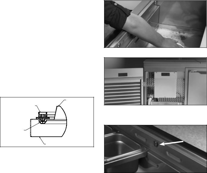
VI. d - CLEANING THE RAIL AREA :
WARNING: DISCONNECT ELECTRICAL POWER SUPPLY BEFORE CLEANING ANY PARTS OF THE UNIT.
Temperature rail is equipped with drain and flush valve. Up to 5 gallons of water can be used to clean rail compartment.
For excessive spills the front and rear air baffle in the rail are removable by unscrewing the thumb screws.
Air baffles can be cleaned in a sink using caution not to loose fasteners.
NOTE: Use caution in avoiding getting excessive water down in cabinet ducts with outer air ducts removed.
-4-
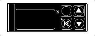
VII. PATENTED MICROPROCESSOR CONTROL
Your new refrigerator cabinet is equipped with a state-of-the-art patented microprocessor control, which precisely regulates operation and provides alarms when problems occur. It is supplied from the factory completely ready for use and requires no adjustments, but without the audible alarms activated. See pages 5 thru 11 for more information.
|
INTELA-TRAUL |
|
°F |
°C |
SET |
FREEZER |
|
|
PATENTED MICROPROCESSOR CONTROL
VII. a - CONTROL FEATURES:
1- Internal Time Clock
•Eliminates external defrost time clock.
•Defrost cycle can be quickly adjusted to suit individual location and use.
•Must be set at power-up. (See page 8, “Setting the 24-Hour Clock”)
•Will automatically update for Daylight Savings Time.
2- Water Resistant Housing
The face of the control is water resistant to provide for protection during cleaning.
3- Parameter/Service Levels
• See “Customer / Service Parameters” on Page 7.
4- Defrost Lockouts
See “Setting Defrost Lockouts” on page 10.
Customers can set up to 4 different defrost lockout periods. The lockout prevents the unit from going into a defrost cycle during peak kitchen use.
Note: The 24-hour clock must be set for this feature to operate correctly.
5- Communication Ability
A NAFEM Data Protocol (NDP) compliant RS-485 serial communications port is available to interface with data collection software (by others). All microprocessor control equipped models are capable of communicating within a NAFEM Data Protocol network if provided with an optional Gateway Hub (available from Traulsen). The actual communications software is available from a number of third party software vendors.
6- Alarms (See the following pages for explanations)
•High Cabinet Air Temperature
•Low Cabinet Air Temperature
•Loss Of Power
•Sensor Failure
•Clean Condenser
7- Display Features
•3-Digit LED Display
•Defrost in Progress Icon
•Fahrenheit or Celsius Temperature Scale In Use
-5-
 Loading...