


Quality Refrigeration
OWNER’S MANUAL
Instructions for the installation, operation and maintenance of all Traulsen:
G-Series Reach-In Refrigerators*
G-Series Reach-In Freezers*
G-Series Hinged Glass Door Refrigerators*
*For equipment produced after 3/9/04 only.
This Traulsen unit is built to our highest quality standards. We build our refrigerators, freezers and heated cabinets this way as a matter of pride. This philosophy has made Traulsen the leader in commercial refrigeration since 1938. We thank you for your choice and confidence in Traulsen equipment and we know you will receive many years of utility from this equipment.
All Traulsen units are placed on a permanent record file with the service department. In the event of any future questions you may have, please refer to the model and serial number found on the name tag affixed to the unit. Should you need service, however, call us on our toll free number, 800-825-8220 between 7:30 a.m. and 4:30 p.m. CST, Monday thru Friday. It is our pleasure to help and assist you in every possible way.
INSTALLER
COMPLETE THE FOLLOWING INFORMATION PRIOR TO UNIT INSTALLATION
INITIAL START DATE: |
SERIAL NO. |
MODEL TYPE:
COMPANY/INDIVIDUAL NAME:
INSTALLER:
FORM NUMBER TR35748 REV. 10/04 |
P/N 375-60184-00 |
TABLE OF CONTENTS
I. THE SERIAL TAG |
Page 1 |
II. RECEIPT INSPECTION |
Page 2 |
III. INSTALLATION |
|
a-Location |
Page 2 |
b-Packaging |
Page 2 |
c-Installing Legs or Casters |
Page 2 |
d-Shelf Pins |
Page 3 |
e-Removing The Doors & Hardware |
Page 3 |
f-Cord & Plug |
Page 3 |
g-Power Supply |
Page 3 |
h-Wiring Diagram |
Page 3 |
i-Clearance |
Page 4 |
j-Installing Optional Interior Kits |
Page 4 |
k-ON/OFF Switch |
Page 4 |
IV. OPERATION |
|
a-Refrigerators |
Page 4 |
b-Freezers |
Page 4 |
c-Light Switch |
Page 4 |
V. CARE & MAINTENANCE |
|
a-Cleaning The Condenser |
Page 5 |
b-Hinge Replacement |
Page 5 |
c-Replacing The Gaskets |
Page 5 |
d-Cleaning The Exterior |
Page 6 |
e-Cleaning The Interior |
Page 6 |
f-Adjusting The Shelves |
Page 6 |
VI. OTHER |
|
a-Service Information |
Page 6 |
b-Spare Parts |
Page 6 |
c-Warranty Registration |
Page 6 |
VII. MICROPROCESSOR CONTROL |
|
a-Control Features |
Page 6-7 |
b-Control Panel |
Page 7 |
c-Parts Assembly |
Page 7 |
d-Notes To The User |
Page 8 |
e-Enter The Customer Access Code |
Page 8 |
f-Customer Service Parameters |
Page 9 |
g-Adjusting Thermostat Set Point High |
Page 9 |
h-Adjusting Thermostat Set Point Low |
Page 10 |
i-Changing The Temperature Scale |
Page 10 |
j-Setting The 24-Hour Clock |
Page 11 |
k-Setting The Date |
Page 12 |
l-Setting Daylight Savings Time |
Page 12 |
m-Starting A Manual Defrost |
Page 13 |
n-Setting Defrost Lockouts |
Page 14 |
o-Adjusting The Room Temperature Offset |
Page 15 |
p-Viewing Coil Sensor Temperature |
Page 15 |
VIII. TROUBLE SHOOTING GUIDE |
Page 16 |
IX. SPARE & REPLACEMENT PARTS LISTING |
Page 17-18 |
X. INDEX |
Page 18 |
XI. WARRANTY INFORMATION |
Back Cover |
FORT WORTH, TX.
SERIAL |
MODEL |
|
|
VOLTS |
Hz |
PH |
|
TOTAL CURRENT |
AMPS |
|
|
MINIMUM CIRCUIT |
AMPS |
|
|
MAXIMUM OVERCURRENT PROTECTION |
AMPS |
||
LIGHTS |
WATTS |
|
|
HEATERS |
AMPS |
|
|
REFRIGERANT |
|
TYPE |
OZ |
DESIGN PRESSURE |
|
HIGH |
LOW |
REFRIGERANT |
|
TYPE |
OZ |
DESIGN PRESSURE |
|
HIGH |
LOW |
370-60294-00 REV (A)
I. THE SERIAL TAG
The serial tag is a permanently affixed label upon which is recorded vital electrical and refrigeration data about your Traulsen product, as well as the model and serial number. This tag is located in the upper right interior compartment on all Traulsen G-Series refrigerator and freezer models.
READING THE SERIAL TAG
•Serial = The permanent ID# of your Traulsen
•Model = The model # of your Traulsen
•Volts = Voltage
•Hz = Cycle
•PH = Phase
•Total Current = Maximum amp draw
•Minimum Circuit = Minimum circuit ampacity
•Lights = Light wattage
•Heaters = Heater amperage (Hot Food units only)
•Refrigerant = Refrigerant type used
•Design Pressure = High & low side operating pressures and refrigerant charge
•Agency Labels = Designates agency listings
-1-
II. RECEIPT INSPECTION |
III. INSTALLATION (continued) |
All Traulsen products are factory tested for performance and are free from defects when shipped. The utmost care has been taken in crating this product to protect against damage in transit. All interior fittings have been carefully secured and the legs are boxed and strapped inside to prevent damage. Door keys will be attached to the handle with a nylon strip. The handle is protected by an easily removable nylon netting.
You should carefully inspect your Traulsen unit for damage during delivery. If damage is detected, you should save all the crating materials and make note on the carrier’s Bill Of Lading describing this. A freight claim should be filed immediately. If damage is subsequently noted during or immediately after installation, contact the respective carrier and file a freight claim. Under no condition may a damaged unit be returned to Traulsen & Co. without first obtaining written permission (return authorization).
III.INSTALLATION
III.a - LOCATION:
Select a proper location for your Traulsen unit, away from extreme heat or cold. Allow enough clearance between the unit and the side wall in order to make use of the door stay open feature at 120° (self-closing feature operates up to 90°). The door(s) must be able to open a minimum of 90° in order to make use of the maximum clear door width available.
III. b - PACKAGING:
All Traulsen units are shipped from the factory bolted to a sturdy wooden pallet and packaged in a durable cardboard container. The carton is attached to the wooden skid with the use of large staples. These should first be removed to avoid scratching the unit when lifting off the crate.
Most exterior stainless steel surfaces have a protective vinyl covering to prevent scratching during manufacturing, shipping and installation. After the unit is installed in place of service, remove and discard the covering from all surfaces.
To remove the wooden pallet, first if at all possible, we suggest that the cabinet remain bolted to the pallet during all transportation to the point of final installation. The bolts can then be removed with a 3/4” socket wrench. Avoid laying the unit on its front, side or back for removal of the pallet.
NOTE: Traulsen does not recommend laying the unit down on its front, side or back. However, if you must please be certain to allow the unit to remain in an upright position afterwards for 24 hours before plugging it in so that the compressor oils and refrigerant may settle.
-2-
III. c - INSTALLING LEGS OR CASTERS:
Adjustable 6” high legs are supplied standard for all Traulsen G-Express units. These are shipped from the factory packed inside a cardboard box which is strapped inside the cabinet to the lower shelf. Inside it should contain four (4) legs.
Casters in lieu of legs are available as an optional accessory kit for the same models. These are shipped inside a separate cardboard box. Inside it should contain four (4) casters and sixteen (16) bolts.
WARNING: THE CABINET MUST BE BLOCKED AND STABLE BEFORE INSTALLING LEGS OR CASTERS.
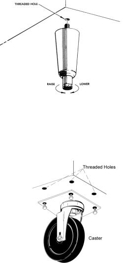
To install the legs or casters, first raise and block the reach-in a minimum of 7” from the floor. For installing legs, thread the legs into the threaded holes on the bottom of the cabinet (see figure 1). Be certain that all legs are tightly secured. When the unit is set in its final position, it is important for proper operation that the unit be level. The legs are adjustable for this purpose, turn the bottom of the leg counterclockwise to raise it, clockwise to lower it. Level the unit from front to back as well as side to side in this manner, using a level placed in the bottom of the cabinet.
Fig. 1
Please note that Traulsen units are not designed to be moved while on legs. If the unit requires moving, a pallet jack or forklift should be used to prevent damage. For installing casters, the casters are “plate” type, and require the use of four (4) bolts each to secure them firmly to the cabinet bottom at each corner (see figure 2). The caster bolts are tightened using a 1/2” socket wrench.
Fig. 2
III. INSTALLATION (continued)
III. d - SHELF PINS:
The unit is supplied with shelves and shelf pins installed. Check all shelf pins to assure they are tightened down as they may have come loose during shipping. Rotate the pins clockwise until they are secured against the side of the cabinet.
III. e - REMOVING THE DOORS & HARDWARE:
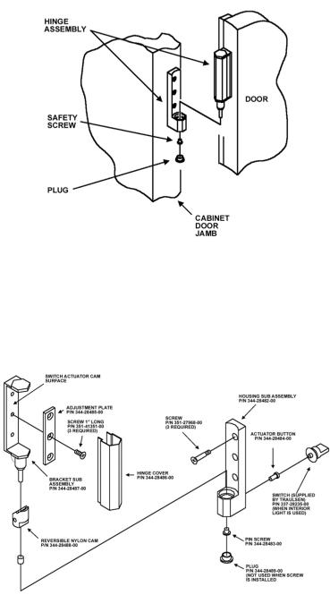
In order to fit through narrow (less than 35”) doorways, it may be sometimes be necessary to remove the door(s), and/or hinges. To remove any solid door, begin by removing the plug at the bottom of the top hinge. Inside the hinge there is a small screw which secures the door in place. Remove this with a flat head screwdriver and the door can then be lifted off the hinge (see figure 3).
Fig. 3
After removing the door, it is now necessary to remove the hinge assembly and hardware from the door itself.
To remove the door portion of the hinge from the door, lift off the hinge cover and then remove the three Phillips head screws which secure the hinge in place on the door (see figure 4).
III. e - REMOVING THE DOORS & HARDWARE (cont’d): If it is also necessary to remove the hinge hardware from the cabinet as well, begin by removing the three Phillips head screws which hold it in place. Set these components aside for later reassembly (see figure 4).
NOTE: All solid door units include a microswitch for controlling the interior lighting in the top hinge(s). Special care should be taken to not damage the wiring for this during the hinge removal process.
The lock keeper will also need to be removed in order to reduce theroverall cabinet depth to 32”.
Begin by removing the two (2) Phillips head screws which secure the lock keeper actuator to the lock keeper bracket.
Next remove the lock keeper bracket by removing the two (2) flat head screws which secure it in place. Set these components aside for later reassembly.
To re-install the door and/or hinges, please reverse the appropriate sections of the preceding procedure.
III. f - CORD & PLUG:
Most self-contained models are supplied with a cord & plug attached. It is shipped coiled at the top of the cabinet, secured by a nylon strip. For your safety and protection, all units supplied with a cord and plug include a special three-prong grounding plug on the service cord. Select only a dedicated electrical outlet with grounding plug for power source. NOTE: Do not under any circumstances, cut or remove the round grounding prong from the plug, or use an extension cord.
III. g - POWER SUPPLY:
The supply voltage should be checked prior to connection to be certain that proper voltage for the cabinet wiring is available (refer to the serial tag to determine correct unit voltage). Make connections in accordance with local electrical codes. Use qualified electricians.
Use of a separate, dedicated circuit is required. Size wiring to handle indicated load and provide necessary overcurrent protector in circuit (see amperage requirements on the unit’s serial tag).
III. h - WIRING DIAGRAM:
Refer to the wiring diagram for any service work performed on the unit. Should you require one, please contact Traulsen Service at (800) 825-8220, and provide the model and serial number of the unit involved.
Fig. 4
-3-
III. INSTALLATION (continued) |
IV. OPERATION (continued) |
III. i - CLEARANCE:
In order to assure optimum performance, the condensing unit of your Traulsen unit MUST have an adequate supply of air for cooling purposes. Therefore, the operating location must either have a minimum of 12” clearance overhead of the condensing unit or allow for unrestricted air flow at the back of the unit. Clearance of at least 12” above is required in order to perform certain maintenance tasks.
III. j - INSTALLING OPTIONAL INTERIOR KITS:
In addition to their standard interiors, G-Express models also offer the option for additional shelves or tray slides. If ordered, these are shipped as kits along with the unit, packaged in a separate cardboard box which contains all the necessary parts and hardware for onsite installation.
To install additional shelves, first remove the white plastic covers from inside the cabinet. These are located along the same vertical line as the pins already in place on the interior side walls, back and center mullion (two and three-section models). This exposes threaded holes in which you may position the new shelves. Next insert the gray plastic shelf pins into these holes and tighten by turning clockwise with your fingers. After all four pins are in place, the new shelf should be placed to rest on top of them. The unused plastic covers may be discarded or saved for future changes to the cabinet interior.
Installation of optional tray slides varies with each cabinet, and with each type of tray slide ordered. To install optional tray slides, follow the directions packaged inside the kit carton.
III. k - ON/OFF SWITCH:
An ON/OFF toggle switch for the power supply is provided. It is located on top of the unit, mounted to the side of the evaporator housing. This is shipped from the factory in the ON position.
IV. OPERATION
IV. a - REFRIGERATORS:
Both refrigerators and freezers do not require manual defrosting. During normal operation, a refrigerator continuously circulates above freezing cabinet air through the coil. A compressor “OFF” cycle occurs every hour to melt any frost which may accumulate on the coil during the compressor “ON” cycle. The control will read “dEF” when this occurs. With standard holding refrigerators, high relative humidity is also maintained to prevent dehydration of stored product.
IV. b - FREEZERS:
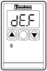
During normal operation, a freezer continuously circulates below freezing cabinet air through the coil. The coil requires a periodic defrosting for proper operation. This is accomplished by an automatic, time activated, temperature/time terminated, defrost program. The controller is preset at the factory for six equally spaced defrost cycles within each 24-hour period.
At the start of a freezer defrost cycle, both the compressor and evaporator fans are off. The microprocessor control will read “dEF” (see figure 5).
°F |
°C |
SET
FREEZER
Fig. 5
The electric heater (attached to the coil) is energized. When a temperature device affixed to the coil senses 70°F (models with electric defrost), the coil is fully defrosted and the compressor operation is resumed, defrost heaters are automatically turned off. The coil fans are delayed from starting at the termination of a defrost cycle. Fan operation is automatically resumed, or they can also be started by a time or temp delay (whichever comes first). In case of temp delay, it uses the same coil sensor and starts at 32°F. The total refrigeration system operation is then resumed. During freezer defrost operation, heat is confined to the coil enclosure to prevent any significant rise in temperature within the food zone. The fan delay controls function upon termination of a defrost cycle is twofold. First, to prevent blowing warm air into the food storage area. Second, to prevent any condensation on the defrost coil from being blown into the food storage area.
The microprocessor control is set from the factory to terminate defrost at 20 minutes in the event of a sensor failure. This setting should never be tampered with, without first consulting the factory.
-4-
IV. OPERATION (continued)
IV. d - LIGHT SWITCHES:
All G-Express models (except sliding glass door models) include a concealed light switch mounted in the top door hinge(s), which automatically activates the interior light when the door is opened. When the door is closed, the lights are not operating.
In addition, on glass door models, an exterior mounted, illuminated red switch is included for manual light control. In the ON position, the lights are illuminated whether the doors are open or not. In the OFF position, the lights are controlled by the hinge switch as described in the first paragraph.
V. CARE & MAINTENANCE
WARNING: DISCONNECT ELECTRICAL POWER SUPPLY BEFORE CLEANING ANY PARTS OF THE
UNIT.
V. a - CLEANING THE CONDENSER:
The most important thing you can do to insure a long, reliable service life for your Traulsen is to regularly clean the condenser coil.
Fig. 5
Remove
Screws
Fig. 6
Lift-Up Louver
Assembly
The condensing unit requires regularly scheduled cleaning to keep the finned condenser clean of lint and dust accummulation. Keeping the condenser clean allows the cabinet to operate more efficiently and use less energy. To clean the condenser, first disconnect electrical power to the cabinet and lift up the front louver assembly. To lift this, remove the two screws located on both sides at the bottom of the louver assembly (see figure 5). Once the screws are removed, the panel can be pivoted upwards allowing full access to the front facing condenser (see figure 6).
V.CARE & MAINTENANCE (cont’d)
V.a - CLEANING THE CONDENSER (cont’d): Vacuum or brush any dirt, lint or dust from the finned condenser coil, the compressor and other cooling system parts. If significant dirt is clogging the condenser fins, use compressed air to blow this clear. Care should be taken not to bend any of the condenser fins, as this will reduce performance and compressor life. Lower louver assembly and replace screws to hold it in place.
V. b - HINGE REPLACEMENT:
Both the door and hinge can be easily removed from the cabinet. To remove the door, remove the plug at the bottom of the top hinge. Inside the hinge there is a small screw which secures the door in place. Remove this with a flat head screwdriver and the door can then be lifted off the hinge. To remove the door portion of the hinge from the door, lift off the hinge cover and then remove the three Phillips head screws which secure the hinge in place on the door. To remove the cabinet portion of the hinge, remove the three Phillips head screws which hold it in place. On solid door units, the top hinge(s) contains a microswitch for controlling the interior lighting.
To reassemble the hinge reverse the previous procedure.
V. c - REPLACING THE GASKETS:
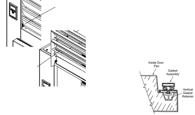
To remove the gasket to be replaced, grasp it firmly by one corner and pull it out. Before attempting to install a new gasket, both the unit and the gasket itself must be at room temperature. Insert the four corners first by using a rubber mallet (or hammer with a block of wood). After the corners are properly inserted, work your way towards the center from both ends by gently hitting with a mallet until the gasket is completely seated in place (see figure 7 for proper gasket placement).
Fig. 7
NOTE: The gasket may appear too large, but if it is installed as indicated above it will slip into place.
-5-
 Loading...