


Traulsen TBC13, TBC1H, TBC1HR, TBC2H, TCB2HR User Manual
...Traulsen Refrigeration
SERVICE MANUAL #07
Instructions For The Installation,
Troubleshooting And Repair Of Traulsen
epicon® Equipped Blast Chiller Models
Undercounter Model TBC5
Reach-In Model TBC13
Roll-In/Roll-Thru Models TBC1H, TBC1HR, TBC2H & TBC2HR
-NOTICE-
This Manual is prepared for the use of trained Authorized Traulsen Service Agents and should not be used by those not properly qualified. This manual is not intended to be all encompassing, but is written to supplement the formal training, on-the-job experience and other product knowledge acquired by Authorized Traulsen Service Agents. Before proceeding with any work, you should read, in its entirety, the repair procedure you wish to perform to determine if you have the necessary tools, instruments and skills required to perform the procedure. Procedures for which you do not have the necessary tools, instruments and skills should be performed only by a trained Authorized Traulsen Service Agent.
Reproduction or other use of this Manual, without the express written consent of Traulsen, is prohibited.
FORM NUMBER TR99999 - REV. 8/13
I. TABLE OF CONTENTS
I. TABLE OF CONTENTS |
1 |
II. GENERAL INFORMATION |
|
a-Introduction |
2 |
b-Operation |
2 |
c-Cleaning |
2 |
d-Applicable Models |
2 |
e-Wiring Diagrams |
2 |
f-Tool Requirements |
2 |
g-The Serial Tag |
2 |
III. SPECIFICATIONS/OPERATING DATA |
|
a-Product Specifications |
3 |
b-Operating Data |
3 |
c-Refrigeration System Installation |
3 |
IV. SERVICING THE EPICON CONTROL |
|
a-Overview |
4 |
b-The Toolbox |
4 |
c-Setting The Clock |
4 |
d-Service Menu |
4 |
e-Service Menu Features |
5 |
V. CONTROL ARCHITECTURE |
|
a-Controller Board |
6 |
VI. COMPONENT FUNCTION |
7 |
VII. SEQUENCE OF OPERATION |
|
a-Refrigeration System |
8 |
b-Refrigeration System (BC compressor on TBC1H only) |
8 |
c- IDLE Mode |
8 |
d- Hold Mode |
8 |
e-By Time Chill/Freeze Mode |
8 |
f-By Temp Chill/Freeze Mode |
9 |
g-By Product Chill/Freeze Mode |
9 |
h-Defrost Mode` |
9 |
VIII. SERVICE PROCEDURES
a-Temperature Sensors |
9 |
b-Expansion Valve |
9-10 |
c-Door Perimeter Heaters |
10 |
d-Compressor |
10-11 |
e-Condenser Fan Assembly |
11 |
f-Condenser Coil |
11 |
g-Pressure Control |
11 |
h-Evaporator Coil |
11 |
i-Filter/Drier |
12 |
j-Evaporator Blower |
12 |
k-Checking For Leaks |
13 |
l-Evacuating The System |
13 |
m-Charging The System |
14 |
n-System Clean-Up |
14 |
o-Replacing The Door Gasket |
15 |
IX. WIRING DIAGRAMS - TBC5 |
16 |
X. WIRING DIAGRAMS - TBC13 |
17 |
XI. WIRING DIAGRAMS - TBC1H MODELS |
18 |
XII. TROUBLESHOOTING |
19-20 |
XIII. TBC5 REPLACEMENT PARTS LIST |
21 |
XIV. TBC13 REPLACEMENT PARTS LIST |
22 |
XV. TBC1H REPLACEMENT PARTS LIST |
23 |
Visit the Resource Center @ www.traulsen.com to review the Operator’s Video for this product.
-1-

II. GENERAL INFORMATION
II. a - INTRODUCTION:
Blast Chillers are food processing refrigerators designed for rapid chilling of product from 140 F to 40 F in approximately 90 minutes, for reheating and/or serving at a later time.
These models aid in preserving food quality, texture and nutritional value, in addition to enhancing food safety.
All of the information, illustrations and specifications contained within this manual are based on the latest product information available at the time of printing.
II. b - OPERATION:
Refer to the instructions contained in the Owner’s Manual, form number TR35938, for specific operating instructions.
II. c - CLEANING:
Detailed cleaning instructions are included with each unit, however, special care MUST be given to the condenser coil(s). These must be cleaned WEEKLY. This surface must be kept free of dirt and grease for proper system operation. This can be done with a vacuum cleaner using a brush attachment, or a stiff brush or wisk broom. Care must be taken not to damage the condenser coil fins. For more information please refer to section V. a, V. e, and V. f of the Blast Chill Owner’s Manual.
II. d - APPLICABLE MODELS:
This manual applies to the following Traulsen models:
TBC5 Undercounter Blast Chiller TBC13 Reach-In Blast Chiller
TBC1H & TBC2H Roll-In Blast Chillers TBC1HR & TBC2HR Roll-Thru Blast Chillers
PLEASE NOTE: This manual refers to the above models built after June 2012, equipped with the epicon® control. For information regarding models built prior to that date please contact the factory.
II. e - WIRING DIAGRAMS:
Refer to the wiring diagrams on pages 16 thru 18 for any service work performed on the unit. Should you require another copy, please contact Traulsen Service at (800) 825-8220, and provide the model and serial number of the unit involved.
II. f - TOOL REQUIREMENTS:
For most jobs a standard set of hand tools, a VOM with AC current tester, electrically conductive field service grounding kit, along with a temperature tester or thermometer are adequate. However in some cases the following additional tools may be required as well:
II.f - TOOL REQUIREMENTS (cont’d):
•Refrigeration Reclaiming Equipment
•Acetylene Torch
•Nitrogen Bottle With Gauges
•Refrigeration Gauge Manifold
•Dial-a-Charge
•Valve Core Removal Kit
•Vacuum Pump
II. g - THE SERIAL TAG:
The serial tag is a permanently affixed sticker on which is recorded vital electrical and refrigeration data about your Traulsen product, as well as the model and serial number. This tag is located inside all blast chiller models. An example is shown below.
FORT WORTH, TX.
SERIAL |
MODEL |
|
VOLTS |
Hz |
PH |
TOTAL CURRENT |
AMPS |
|
MINIMUM CIRCUIT |
AMPS |
|
MAXIMUM OVERCURRENT PROTECTION |
AMPS |
|
LIGHTS |
WATTS |
|
HEATERS |
AMPS |
|
REFRIGERANT |
TYPE |
OZ |
DESIGN PRESSURE |
HIGH |
LOW |
REFRIGERANT |
TYPE |
OZ |
DESIGN PRESSURE |
HIGH |
LOW |
|
370-60294-00 REV (A) |
|
READING THE SERIAL TAG
•Serial = The permanent ID# of your Traulsen
•Model = The model # of your Traulsen
•Volts = Voltage
•Hz = Cycle
•PH = Phase
•Total Current = Maximum amp draw
•Minimum Circuit = Minimum circuit required
•Lights = Light wattage
•Heaters = Heater amperage
•Refrigerant = Refrigerant type used
•Design Pressure = High & low side operating pressures and refrigerant charge
•Agency Labels = Designates agency listings
-2-
III.SPECIFICATIONS/OPERATING DATA/INSTALLATION
III.a - PRODUCT SPECIFICATIONS:
DIMENSIONS |
TBC5 |
TBC13 |
TBC1H |
TBC1HR |
TBC2H |
TBC2HR |
Length - Overall in. |
54 |
41 |
48-1/2 |
48-1/2 |
48-1/2 |
48-1/2 |
Depth - Overall in. |
34-7/16 |
34-1/2 |
37-5/8 |
41-1/4 |
71-5/6 |
75-1/4 |
Height - Overall in. |
34 |
74 |
90-3/8 |
90-3/8 |
90-3/8 |
90-3/8 |
Capacity 12 x 20 Pans |
10 |
26 |
1 Rack |
1 Rack |
2 Racks |
2 Racks |
Capacity 18 x 26 Pans |
5 |
13 |
1 Rack |
1 Rack |
2 Racks |
2 Racks |
Capacity Product Weight |
100 lbs. |
200 lbs. |
300 lbs. |
300 lbs. |
600 lbs. |
600 lbs. |
III. b - OPERATING DATA:
DATA |
TBC5 |
TBC13 |
TBC1H |
TBC1HR |
TBC2H |
TBC2HR |
Single or Dual System |
Single |
Dual |
Dual |
Dual |
Dual |
Dual |
Remote Chill Compressor n/a |
No |
Yes |
Yes |
Yes(2) |
Yes(2) |
|
H.P.1 |
1 |
1/2 |
1/2 |
1/2 |
1/2(2) |
1/2(2) |
BTU/HR1 |
4300 |
2820 |
2820 |
2820 |
2820(2) |
2820(2) |
H.P.2 |
n/a |
1-1/4 |
4 |
4 |
4(2) |
4(2) |
BTU/HR2 |
n/a |
5710 |
18,700 |
18,700 |
18,700(2) |
18,700(2) |
Refrigerant Type |
R-404A |
R-404A |
R-404A |
R-404A |
R-404A |
R-404A |
Refrigerant Charge oz. |
29 |
31 |
25 |
25 |
25(2) |
25(2) |
Refrigerant Charge2 |
n/a |
45 |
See Note3 |
See Note3 |
See Note3 |
See Note3 |
Condenser RLA1 |
11.7 |
5.1 |
10.5 |
10.5 |
10.5(2) |
10.5(2) |
Condenser RLA2 |
n/a |
9.3 |
See Note3 |
See Note3 |
See Note3 |
See Note3 |
Unit Voltage |
115 |
208/115 |
115 |
115 |
115(2) |
115(2) |
Phase |
1 |
1 |
1 |
1 |
1 |
1 |
Hz |
60 |
60 |
60 |
60 |
60 |
60 |
Full Load Amps |
13.3 |
13.4 |
14.9 |
14.9 |
14.9(2) |
14.9(2) |
NEMA Plug Type |
5-20 |
14-20 |
Hard Wire |
Hard Wire |
Hard Wire |
Hard Wire |
1= Self-Contained Holding or Primary Compressor. 2= Blast Chilling or Secondary Compressor.
3= Varies with remote system.
III. c - REFRIGERATION SYSTEM INSTALLATION:
All Traulsen blast chillers, with the exception of model TBC5, require the use of a floor drain or floor mounted condensate evaporator for condensate removal. Refer to Section IV. h of the blast chill owner’s manual for more information.
Remote refrigeration installation requirements apply only to models TBC1H/TBC1HR and TBC2H/TBC2HR. Aremote condensing unit, operating on R-404Arefrigerant, is required for Blast Chill operation on these models. The remote condensing unit(s) should be capable of providing 18,700 BTU/hr @ -10°F evaporator temperature and 90°F ambient.
Air-cooled and water-cooled remote condensing units are available from Traulsen as an optional accessory. Please note that these should be adequate for any installation within a 25 foot radius from the cabinet. Beyond this distance, the actual capacity of the remote condensing unit and line sizing may change depending upon the length and layout of the connecting piping from the remote condensing unit to the Blast Chiller. These utilize a 1/2” liquid and 1-1/8” suction lines. Proper specification of the remote condensing unit needed and line sizing should be defined by a qualified refrigeration engineer or technician, based on the jobsite installation needs.
The low pressure cut-out of the remote condensing unit should be adjusted to obtain an evaporator coil temperature NO LOWER THAN -15°F. If the length of the connecting piping is 40 feet or less, the condensing unit low pressure cut-out settings will be approximately 15 +/- 2 PSIG cut-out and 25+/- 3 PSIG cut-in.
For more information please contact the factory.
-3-
IV. SERVICING THE EPICON CONTROL
IV. a - OVERVIEW:
Traulsen’s TBC Series blast chillers are equipped with the epicon microprocessor control. This is protected from damage by a surrounding heavy gauge metal bezel. It includes several diagnostic features built within the TOOLBOX’s SERVICE menu. The control itself has no serviceable parts. Should you encounter a faulty or damaged control, it will need to be replaced.
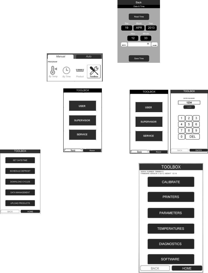
IV. b - THE TOOLBOX:
The TOOLBOX can be accessed by pressing the MANUAL tab, and then the TOOLBOX icon on top of the MANUAL menu screen.
From the MANUAL menu screen press the TOOLBOX icon.
The control will now display the TOOLBOX menu. It includes three security levels.
Press USER for operator level access. This provides open access allowing you to: Set the Clock, Adjust Defrost Time and Settings, Download Cycle Data,
Search Chill Cycle History, and Upload Recipes to the
PRODUCT menu.
Press SUPERVISOR for supervisor access. Note that this not intended for every day access and adjustments and so is password protected
Enter your access code to proceed. The factory default code is 1234. This can be changed in the
SUPERVISOR level.
IV. c - SETTING THE CLOCK:
Begin by pressing MANUAL - TOOLBOX - USER, then press SET DATE/TIME. The display will change to the SET DATE/TIME screen.
IV. c - SETTING THE CLOCK (continued): To adjust the Date and time settings:
1)Press DAY - MONTH - YEAR - HOUR - MINUTE as needed (after doing so the field will be highlighted).
2)Toggle the LEFT/RIGHT arrows at bottom to adjust this parameter
3)Proceed to the next parameter.
4)Press SAVE TIME to save these settings.
IV. d - SERVICE MENU:
Press SERVICE to access the service menu. Note that this is password protected. The factory default code is 4401. Enter the access code to proceed.
The SERVICE menu will appear.
-4-
IV. SERVICING THE EPICON CONTROL (cont’d)
IV. e - SERVICE MENU FEATURES:
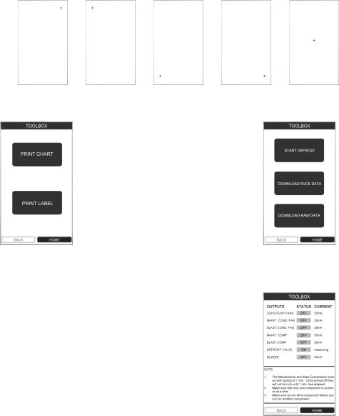
CALIBRATE: This features allows for calibration of the touchscreen’s accuracy. Press CALIBRATE than each of the five plus symbols (+) as closely as possible to do so. Note use of a stylus is highly recommended.
NOTE: The units are calibrated from the factory and should only be recalibrated if necessary. Exercise extreme caution
when recalibrating as improper inputs while calibrating can result in difficultly navigating the control.
Touch |
Touch |
Touch |
Touch |
Touch |
Point 1 |
Point 2 |
Point 3 |
Point 4 |
Point 5 |
PRINTERS: This feature allows you to check each printer for proper operation.
Press PRINT CHART to test the record printer.
Press PRINT LABEL to test the label printer on models supplied with the optional label printer.
TEMPERATURES:
Displays key temperature sensor data. Expected values for each should be in similar to those shown below...
AMBIENT |
66°F |
CABINET |
34°F |
MAINT EVAP IN |
63°F |
MAINT EVAP CORE |
42°F |
BLAST EVAP IN |
32°F |
BLAST EVAP CORE |
37°F |
BLAST EVAP OUT |
32°F |
BLAST LIQUID LINE |
66°F |
MAINT LIQUID LINE |
66°F |
SOFTWARE:Selectthisfeaturewhenupdatingthecontrol’s operating software.
The current software versions are displayed at the top of the TOOLBOX main menu. Contact Traulsen at (800) 825-8220 to verify if you have the latest software versions.
To update the control, insert a thumb drive containing the latest software into the USB port. Note all files must be locatedintherootdirectory. Updatesshouldbeperformed in the following order (if necessary)...
Update I/O Board
Update UI Board
Update HTML
Follow the instructions provided with the software update and any on screen instructions. Do not remove the thumb drive until all updates have been completed.
-5-
PARAMETERS:
Press START DEFROST to initiate an on demand defrost cycle.
Press DOWNLOAD SERVICE DATA to transferalltemperaturedata(asshown on the TEMPERATURE menu) through the USB port to a thumb drive.
Press DOWNLOAD RAW DATA to transfer all data in memory through the USB port to a thumb drive. NOTE: this featurerequiresuseofspecialsoftware available from Traulsen.
DIAGNOSTICS:
Press each OUTPUT one at a time in order to change test status from OFF to ON. Record the reading and then turntheOUTPUToffbeforeproceeding to the next one.
NOTE: If you do not turn each OUTPUT off before proceeding to the next one you can potentially cause damage to that component.
Normal readings for each OUTPUT
should be...
LS EVAP FANS = 3.7A +/- .55A HS EVAP FANS = 3.9A +/- .15A MAINT COND FAN = 1.15A +/- .25A BLAST COND FAN =
MAINT COMP = 7.5A +/- 1.5A BLAST COMP =
DEFROST VALVE = n/a BUZZER = n/a
NOTE: The maintenance compressor has an anti-cycling feature of 1-minute. Allow the cabinet to idle for at least 1-minute before beginning a test.

V. CONTROL ARCHITECTURE
LEGEND
1. |
UI Power |
5. |
Label Printer Communication |
2. |
USB Port (used) |
6. |
Paper Printer Power |
3. |
USB Port (unused) |
7. |
Paper Printer Communica- |
tion |
|
|
|
4. |
Label Printer Power |
|
|
-6-
|
VI. COMPONENT FUNCTION |
Compressor |
Pumps refrigerant through refrigeration lines and components. |
Condenser Fan |
Draws air across condenser coil to aid in removing heat from the refrigerant and |
|
moves air across compressor to aid in cooling the compressor. |
Dual Pressure Control |
Low side monitors suction pressure at compressor. Shuts compressor OFF when |
(TBC1H & TBC2H only) |
low pressure setting is reached (cut-out). Allows compressor to run when |
|
pressure rises to cut-in setting. |
|
High side monitors discharge pressure at compressor. Shuts compressor OFF |
|
when high side pressure setting is reached (cut-out). Allows compressor to run |
|
when pressure returns to cut-in setting. |
|
The differential is the difference in pressure between open and closed states of the |
|
pressure switch. |
Start Capacitor |
Wired in series with the start windings to help start compressor motor. |
Run Capacitor |
Continually in circuit to help compressor motor during operation. |
Thermal Overload |
Removes power from compressor if the internal temperature of the compressor |
|
becomes too high (auto reset). |
Start Relay |
Senses current of run winding of compressor motor. Normally open contacts |
|
close when run winding draws a high amperage at start and brings the start |
|
capacitor and start windings into the circuit. As the motor reaches operating |
|
speed (less amperage through run winding), the normally open contacts open and |
|
removes the start capacitor and start windings from the circuit. |
Evaporator Fan |
Draws air from the cabinet and moves air through the evaporator coil. |
Defrost Heater |
Defrosts evaporator coils and prevents water droplets from evaporator coil from |
|
freezing before they can drain to the condensate pan. Operates only during |
|
defrost cycle. |
Air Temperature Sensor |
Monitors air temperature inside the cabinet. |
Coil Temperature Sensor |
Monitors the suction line temperature at evaporator during defrost cycle. |
Food Temperature Probe |
Monitors temperature of food product. |
Solenoid Valve |
Normally closed. When energized, allows refrigerant to flow from receiver to |
|
evaporator coil. |
Door Perimeter Heater |
Prevents condensate on door frame. |
Controller |
Performs the following functions: |
|
a) Displays all data for the current mode of operation. |
|
b) Cycles refrigeration system to maintain cabinet temperature. |
|
c) Monitors power failures. |
Power Supply Boards |
Provides DC voltage to control system. |
Relay Board |
Performs the following functions: |
|
a) Cycles fans. |
|
b) Controls outputs to heaters and compressor relays. |
Thermal Fuse |
TBC1H, TBC1HR, TBC2H and TBC2HR only. Monitors cabinet air temperature. |
|
Opens circuit to defrost heater if cabinet temperature exceeds 230°F. |
-7-
 Loading...