


Traulsen TE036HT, TE048HT, TE060HT, TE065HT, TE072HT Service Manual
...Traulsen Refrigeration
SERVICE MANUAL #07
Instructions For The Troubleshooting
And Repair Of All Traulsen TE-Series
Refrigerated Equipment Stand Models
-NOTICE-
This Manual is prepared for the use of trained Authorized Traulsen Service Agents and should not be used by those not properly qualified. This manual is not intended to be all encompassing, but is written to supplement the formal training, on-the-job experience and other product knowledge acquired by Authorized Traulsen Service Agents. Before proceeding with any work, you should read, in its entirety, the repair procedure you wish to perform to determine if you have the necessary tools, instruments and skills required to perform the procedure. Procedures for which you do not have the necessary tools, instruments and skills should be performed only by a trained Authorized Traulsen Service Agent.
Reproduction or other use of this Manual, without the express written consent of Traulsen, is prohibited.
FORM NUMBER TR35896 - REVISED. 4/08
TABLE OF CONTENTS
I. THE SERIAL TAG |
1 |
IV. REPLACING THE... (cont’d) |
|
||
|
|
|
f. |
Compressor |
10 |
II. GENERAL INFORMATION |
|
|
|
|
|
a. |
Introduction |
2 |
V. WIRING DIAGRAMS |
|
|
b. |
Model Designations |
2 |
a. |
115V Refrigerator Models |
11 |
c. |
Wiring Diagrams |
2 |
|
|
|
d. |
Installation - See Owner’s Manual |
2 |
VI. SERVICE PROCEDURES & ADJUSTMENTS |
|
|
e. |
Cleaning |
2 |
a. |
System Access |
12 |
f. |
Tools |
2 |
b. |
Sweat On Piercing Valves |
12 |
g. |
Refrigeration System Theory Of Operation |
2 |
c. |
Refrigerant Leak Check |
12 |
h. |
Air Flow Requirements |
2 |
d. |
Evacuating System |
13 |
i. |
The Microprocessor Control |
2 |
e. |
Charging System |
13 |
j. |
Control Locations |
3 |
f. |
System Clean-Up |
14 |
k. |
Specifications |
3 |
g. |
Heater Test/Drawer Perimeter Heater |
14 |
l. |
Operating Data Chart |
3 |
|
|
|
|
|
|
VII. ELECTRICAL OPERATION |
|
|
III. REMOVAL & REPLACEMENT OF PARTS |
|
a. |
Sequence Of Operation/Normal Operation |
14 |
|
a. |
Louver Assembly |
4 |
b. |
Sequence Of Operation/Defrost Mode |
14 |
b. |
Evaporator Housing Cover |
4 |
c. |
Component Function |
15 |
c. |
Removing The Drawer |
4 |
d. |
Installation of Sensors |
15 |
d. |
Removing The Drawer Frame (slides) |
4 |
|
|
|
e. |
Drawer Gaskets |
5 |
VIII. REPLACEMENT PARTS LISTING |
16 |
|
f. |
Microprocessor Control |
5 |
|
|
|
g. |
Condensate Drain Pan |
5 |
IX. TROUBLESHOOTING |
17 |
|
h. |
Accessing Start Components |
5 |
|
|
|
IV. REPLACING THE... |
|
|
|
|
|
a. |
Condenser Fan Motor and/or Blade |
6 |
|
|
|
b. |
Condenser Coil |
7 |
|
|
|
c. |
Evaporator Fan |
8 |
|
|
|
d. |
Evaporator Coil |
9 |
|
|
|
FORT WORTH, TX.
SERIAL |
MODEL |
|
|
VOLTS |
Hz |
PH |
|
TOTAL CURRENT |
AMPS |
|
|
MINIMUM CIRCUIT |
AMPS |
|
|
MAXIMUM OVERCURRENT PROTECTION |
AMPS |
||
LIGHTS |
WATTS |
|
|
HEATERS |
AMPS |
|
|
REFRIGERANT |
|
TYPE |
OZ |
DESIGN PRESSURE |
|
HIGH |
LOW |
REFRIGERANT |
|
TYPE |
OZ |
DESIGN PRESSURE |
|
HIGH |
LOW |
370-60294-00 REV (A)
I. THE SERIAL TAG
The serial tag is a permanently affixed sticker on which is recorded vital electrical and refrigeration data about your Traulsen product, as well as the model and serial number. This tag is located on the upper right interior wall of all TE-Series models.
READING THE SERIAL TAG
•Serial = The permanent ID# of your Traulsen
•Model = The model # of your Traulsen
•Volts = Voltage
•Hz = Cycle
•PH = Phase
•Total Current = Maximum amp draw
•Minimum Circuit = Minimum circuit required
•Lights = Light wattage
•Heaters = Heater amperage
•Refrigerant = Refrigerant type used
•Design Pressure = High & low side operating pressures and refrigerant charge
•Agency Labels = Designates agency listings
-1-
II. GENERAL INFORMATION
II. a - INTRODUCTION:
This manual applies to the following Traulsen models only:
TE036HT, TE048HT, TE060HT, TE065HT, TE072HT TE084HT, TE096HT, TE110HT, TE125HT & TE139HT
II. b - MODEL DESIGNATIONS:
TE060HT
Position 1: TE = Traulsen Equipment Stand Position 2: 036 = 36” Long Model
048 = 48” Long Model
060 = 60” Long Model Position 3: HT = Refrigerator
II. c - WIRING DIAGRAM:
Refer to the wiring diagram for any service work performed on this unit. A copy is located on the unit when shipped. Should you require another copy, or a wiring diagram for an older production unit, please contact Traulsen Service at (800) 825-8220, and provide the model and serial number of the unit involved (this information is located on the serial tag, see page one).
II. d - INSTALLATION:
Generally TE-Series refrigeration products are installed by the dealer, or others contracted by the dealer or owner. Detailed installation instructions are included along with each unit when shipped.
II. e - CLEANING:
Detailed cleaning instructions are included with each unit, however special care MUST be given to the condenser coil. The condenser coil must be cleaned at a minimum of every six months. This can be done with a vacuum cleaner using a brush attachment, or a stiff brush or wisk broom. For more information please refer to “Section V.a” of the TE-Series Owner’s Manual.
II. f - TOOL REQUIREMENTS:
For most jobs a standard set of hand tools, a VOM and AC current tester, along with a temperature tester or thermometer are adequate. However in some cases the following additional tools may be required as well:
•Refrigeration Guage Manifold
•Refrigeration Reclaiming Equipment
•Acetylene Torch
•Anti-Static Grounding Kit (TL 84919)
•Nitrogen Bottle With Gauges
•Thin 5/16” Open End Wrench
•Refrigerant Reclaim Unit
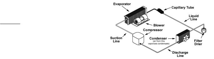
II. g - REF’N SYSTEM - THEORY OF OPERATION: The refrigeration system is the mechanism whereby heat is transferred from the cabinet to the outside air. It works under the principle that the heat moves from hot to cold as it tries to establish equilibrium.
The microprocessor control signals a need for heat to be removed from the cabinet. The compressor begins by compressing the refrigerant gas as it is discharged. The high pressure refrigerant now circulates through the condenser, removing heat from the refrigerant and condensing it into a liquid. From there the refrigerant flows to the filter drier which removes all traces of moisture and particles from the system.
After the filter drier, the refrigerant passes through a “metering device.” Traulsen uses a capillary tube to regulate the flow of refrigerant into the evaporator coils.
In the evaporator coil, heat is transferred from the cabinet to the refrigerant, which changes from a cold liquid to a warm low pressure gas. When the desired cabinet air temperature has been reached, the microprocessor control shuts off the compressor.
Fig. 1 - The Refrigeration System
II. h - AIR FLOW REQUIREMENTS:
To assure optimum performance, the condensing unit of your Traulsen unit MUST have an adequate supply of air for cooling purposes. Therefore, the operating location must allow a minimum of 12” clearance in front of the louvers to allow for unrestricted air flow to the condensing unit.
II. i - THE MICROPROCESSOR CONTROL:
For detailed information on replacement, repair or adjustment of the INTELA-TRAUL® microprocessor control please refer to it’s service manual (form number TR35705).
-2-
II. GENERAL INFORMATION (cont’d)
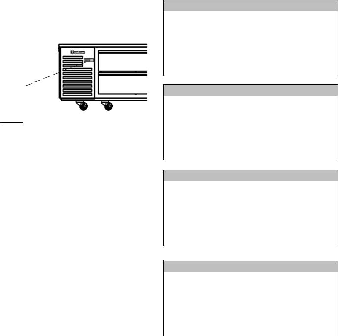
II. j - CONTROL LOCATION:
On all TE-Series refrigerator models, the microprocessor control is located on the louver assembly. The louvers/refrigeration system are mounted standard on the left side, but as an option are available mounted on the right (see figure 2).
Fig. 2
Control Location
II. k - OPERATING DATA CHART:
Refrigerated Models (cabinet temperature set at 38°F)
Ambient |
70°F |
100°F |
Suction Pressure |
35 PSIG |
50 PSIG |
Suction Temperature |
3°F |
16°F |
Discharge Pressure |
200 PSIG |
295 PSIG |
Discharge Temperature |
88°F |
115°F |
II. l - SPECIFICATIONS:
TE-Series Refrigerated Equipment Stands
|
TE036 |
TE048 |
TE060 |
|
|
|
|
Horsepower |
1/3 HP |
1/3 HP |
1/3 HP |
|
|
|
|
Condensing Unit - BTU/HR |
2440 |
2440 |
2440 |
|
|
|
|
Condensing Unit Amp Draw |
4.5 |
4.5 |
4.9 |
|
|
|
|
Fan, Lights, Etc. Amp Draw |
0.6 |
0.6 |
1.1 |
|
|
|
|
Refrigerant |
R-404A |
R-404A |
R-404A |
|
|
|
|
Refrigerant Charge (oz.) |
14.0 |
14.5 |
16.0 |
|
|
|
|
TE-Series Refrigerated Equipment Stands
|
TE065 |
TE072 |
TE084 |
|
|
|
|
Horsepower |
1/3 HP |
1/3 HP |
1/3 HP |
|
|
|
|
Condensing Unit - BTU/HR |
2440 |
2440 |
2440 |
|
|
|
|
Condensing Unit Amp Draw |
4.9 |
4.9 |
4.9 |
|
|
|
|
Fan, Lights, Etc. Amp Draw |
1.1 |
1.1 |
1.1 |
|
|
|
|
Refrigerant |
R-404A |
R-404A |
R-404A |
|
|
|
|
Refrigerant Charge (oz.) |
16.5 |
16.5 |
17.0 |
|
|
|
|
TE-Series Refrigerated Equipment Stands
|
TE096 |
TE110 |
TE125 |
|
|
|
|
Horsepower |
1/2 HP |
1/2 HP |
1/2 HP |
|
|
|
|
Condensing Unit - BTU/HR |
4090 |
4090 |
4090 |
|
|
|
|
Condensing Unit Amp Draw |
9.6 |
9.6 |
9.6 |
|
|
|
|
Fan, Lights, Etc. Amp Draw |
1.5 |
1.5 |
1.5 |
|
|
|
|
Refrigerant |
R-404A |
R-404A |
R-404A |
|
|
|
|
Refrigerant Charge (oz.) |
20.0 |
20.0 |
20.0 |
|
|
|
|
TE-Series Refrigerated Equipment Stands
|
TE139 |
|
|
|
|
|
|
Horsepower |
1/2 HP |
|
|
|
|
|
|
Condensing Unit - BTU/HR |
4090 |
|
|
|
|
|
|
Condensing Unit Amp Draw |
9.6 |
|
|
|
|
|
|
Fan, Lights, Etc. Amp Draw |
1.9 |
|
|
|
|
|
|
Refrigerant |
R-404A |
|
|
|
|
|
|
Refrigerant Charge (oz.) |
21.0 |
|
|
|
|
|
|
-3-

III. REMOVAL & REPLACEMENT OF BASIC PARTS
WARNING: DISCONNECT THE ELECTRICAL POWER TO THE MACHINE
AND FOLLOW LOCKOUT/TAGOUT PROCEDURES.
III. a - LOUVER ASSEMBLY/SYSTEM ACCESS:
To remove the louver assembly first place your hands under the louver panel and lift this up off the bracket and then away from the cabinet face (see figure 3).
Fig. 3
To gain full access to the refrigeration system from the side, remove the cover by removing the bottom screws (see figures 4 & 5).
Fig. 4
Screw
Locations
Fig. 5
Side System
Access
When finished, lower the louver assembly into position and replace the side panel. Secure these in place using the previously removed screws.
III. b - EVAPORATOR HOUSING COVER:
Remove the back cover by removing the four screws which secure this to the cabinet (see figure 6).
Fig. 6
Reverse the procedure when done to reinstall.
III. c - REMOVING THE DRAWERS:
Remove the drawer(s) from the drawer frame by lifting up on the drawer, and then pulling out.
III. d - REMOVING THE DRAWER FRAME:
Once the drawer(s) have been removed, the drawer frame module can also be removed by loosening the front and back clamping knobs (2 of each), located on the cross-rail and liner locks (see figures 7 & 8). Slide the front cross-rail locks towards the center of the drawer frame module and allow the liner locks to drop down from the top of the liner.Pull the drawer frame module forward, tip forward and pull out. The entire frame assembly is now free to slide out of the cabinet.
Fig. 7
Fig. 8
-4-
III. REMOVAL & REPLACEMENT OF BASIC PARTS (cont’d)
WARNING: DISCONNECT THE ELECTRICAL POWER TO THE MACHINE
AND FOLLOW LOCKOUT/TAGOUT PROCEDURES.
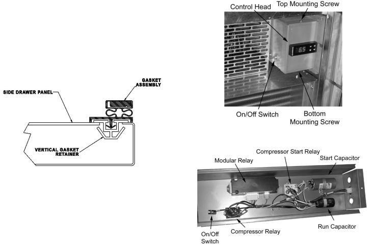
III. e - DRAWER GASKETS:
To remove the gasket to be replaced, grasp it firmly by one corner and pull it out. Before attempting to install a new gasket, both the unit and the gasket itself must be at room temperature. Insert the four corners first by using a rubber mallet (or hammer with a block of wood). After the corners are properly inserted, work your way towards the center from both ends by gently hitting with a mallet until the gasket is completely seated in place (see figure 9 for gasket cross section).
Fig. 9
NOTE: The gasket may appear too large, but if it is installed as indicated above it will slip into place.
III. f - THE MICROPROCESSOR CONTROL:
To remove the microprocessor controller from the unit in which it was installed, please refer to section “V” of your INTELA-TRAUL® Master Service Manual.
III. g - DRAIN PAN:
To remove the drain pan, begin by removing the evaporator housing cover as outlined in section “III. c.” Next, remove the screws and brackets which secure the drain pan, and remove the drain tube from the drain pan. Finish by sliding the drain pan out from under the coil.
Reverse the procedure to install.
III. h - ACCESSING START COMPONENTS:
The start components are located behind the front louver, inside a metal tray.
To access the start components, first remove the louver assembly as shown in section III. a. Next loosen the top set screw (see figure 10). and remove the molex connection in the back of the box to gain access to the back set screw. Slide the electrical box out the font on its tracks.
III. h - ACCESSING START COMPONENTS (cont’d):
Fig. 10
Fig. 11
See figure 11 for component detail.
-5-
 Loading...