


ALT132NUT-HHS
Quality Refrigeration
OWNER’S MANUAL
Instructions for the installation, operation
and maintenance of all Traulsen:
R & A Series Reach-In & Roll-In Refrigerators*
R & A Series Pass-Thru & Roll-Thru Refrigerators*
R & A Series Reach-In & Roll-In Freezers*
R & A Series Reach-In Refrigerator/Freezers*
R & A Series Reach-In & Roll-In Hot Food Cabinets*
R & A Series Pass-Thru & Roll-Thru Hot Food Cabinets*
* Please Note: This manual is intended for use with the above referenced equipment manufactured
after May 1,2006. To obtain a copy of the correct Owner’ s Manual to support the same
products manufactured prior to this date, please contact Traulsen Service at (800) 825-8220.
This Traulsen unit is built to our highest quality standards. We build our refrigerators, freezers and heated
cabinets this way as a matter of pride. This philosophy has made Traulsen the leader in commercial
refrigeration since 1938. We thank you for your choice and confidence in Traulsen equipment and we know
you will receive many years of utility from this equipment.
All Traulsen units are placed on a permanent record file with the service department. In the event of any
future questions you may have, please refer to the model and serial number found on the name tag affixed
to the unit. Should you need service, however, call us on our toll free number, 800-825-8220 between 7:30
am and 4:30 pm CST, Monday thru Friday. It is our pleasure to help and assist you in every possible way.
INSTALLER
COMPLETE THE FOLLOWING INFORMATION PRIOR TO UNIT INSTALLATION
INITIAL START DATE: SERIAL NO.
MODEL TYPE:
COMPANY/INDIVIDUAL NAME:
INSTALLER:
FORM NUMBER TR35743 REV. 10/06 P/N 375-60176-00
TABLE OF CONTENTS
I. THE SERIAL TAG Page 1
II. RECEIPT INSPECTION Page 2
III. INSTALLATION
a-Location Page 2
b-Packaging Page 2
c-Installing Legs or Casters Page 2-3
d-Shelf Pins Page 3
e-Roll-In Model Installation Page 3
f-Attaching Double Depth Units Together Page 3
g-Installing The Condensate Evaporator Page 3-4
h-Remote Installation Page 4
i-Cord & Plug Page 4
j-Power Supply Page 4
k-Wiring Diagram Page 4
l-Clearance Page 4
IV. OPERATION
a-Refrigerators Page 5
b-Freezers Page 5
c-Hot Food Cabinets Page 5
V. CARE & MAINTENANCE
a-Cleaning The Condenser Page 5-6
b-Hinge Replacement Page 6
c-Replacing The Gaskets Page 6
d-Cleaning The Exterior Page 6
e-Cleaning The Interior Page 6
f-Adjusting The Shelves Page 6
g-Replacing The Light Bulb Page 7
h-Replacing The Optional Condenser Filter Page 7
VI. OTHER
a-Service Information Page 7
b-Spare Parts Page 7
c-Warranty Registration Page 7
VII. INTELA-TRAUL
a-Control Features Page 8
b-Alarm Explanations Page 9
c-Control Panel Page 10
d-Notes To The User Page 11
e-Enter The Customer Access Code Page 11
f-Customer Service Parameters Page 12
g-Adjusting Thermostat Set Point High Page 12
h-Adjusting Thermostat Set Point Low Page 13
i-Changing The Temperature Scale Page 13
j-Setting The 24-Hour Clock Page 14
k-Setting The Date Page 15
l-Setting Daylight Savings Time Page 15
m-Starting A Manual Defrost Page 16
n-Setting Defrost Lockouts Page 17
o-Adjusting The Door Perimeter Heaters Page 18
p-Adjusting The Room Temperature Offset Page 18
q-Setting The Audible Alarm Style Page 19
r-Viewing Sensor Temperatures Page 19
s-Door Open Icon Page 19
t-Hot Food Units - Adjusting The Thermostat Page 20
u-Hot Food Units - Turning The Unit OFF & ON Page 20
v-Hot Food Units - Temperature Adjustment Page 20
VIII. TROUBLE SHOOTING GUIDE Page 21
XI. SPARE PARTS LIST Page 22
XII. STAINLESS STEEL OVERVIEW Page 23
XIII. CARE OF STAINLESS STEEL Page 23-24
XIV. CORROSION REMEDIES Page 24
XV. WARRANTY INFORMATION Page 25
XVI. INDEX Page 26
®
FORT WORTH, TX.
SERIAL MODEL
VOLTS Hz PH
TOTAL CURRENT AMPS
MINIMUM CIRCUIT AMPS
MAXIMUM OVERCURRENT PROTECTION AMPS
LIGHTS WATTS
HEATERS AMPS
REFRIGERANT TYPE OZ
DESIGN PRESSURE HIGH LOW
REFRIGERANT TYPE OZ
DESIGN PRESSURE HIGH LOW
370-60294-00 REV (A)
I. THE SERIAL TAG
The serial tag is a permanently affixed sticker on
which is recorded vital electrical and refrigeration data
about your Traulsen product, as well as the model
and serial number. This tag is located in the upper
right interior compartment on all reach-in/pass-thru
and roll-in/roll-thru refrigerator, freezer and dual-temp
models. For hot food models, this tag is located on
the top of the unit behind the louvers to protect it
from the heat.
READING THE SERIAL TAG
• Serial = The permanent ID# of your Traulsen
• Model = The model # of your Traulsen
• Volts = Voltage
• Hz = Cycle
• PH = Phase
• Total Current = Maximum amp draw
• Minimum Circuit = Minimum circuit ampacity
• Lights = Light wattage
• Heaters = Heater amperage (Hot Food units only)
• Refrigerant = Refrigerant type used
• Design Pressure = High & low side operating
pressures and refrigerant charge
• Agency Labels = Designates agency listings
-1-
II. RECEIPT INSPECTION
III. INSTALLATION (continued)
All Traulsen products are factory tested for performance
and are free from defects when shipped. The utmost
care has been taken in crating this product to protect
against damage in transit. All interior fittings have been
carefully secured and the legs or casters are boxed and
strapped inside to prevent damage. Door keys will be
attached to the handle with a nylon strip. The handle is
protected by an easily removable nylon netting.
You should carefully inspect your Traulsen unit for
damage during delivery. If damage is detected, you
should save all the crating materials and make note on
the carrier’s Bill Of Lading describing this. A freight claim
should be filed immediately. If damage is subsequently
noted during or immediately after installation, contact
the respective carrier and file a freight claim. Under no
condition may a damaged unit be returned to Traulsen.
without first obtaining written permission (return
authorization).
III. INSTALLATION
III. a - LOCATION:
Select a proper location for your Traulsen unit, away from
extreme heat or cold. Allow enough clearance between
the unit and the side wall in order to make use of the
door stay open feature at 120° (self-closing feature
operates up to 90°). The door(s) must be able to open a
minimum of 90° in order to make use of the maximum
clear door width available.
III. b - PACKAGING (cont’d):
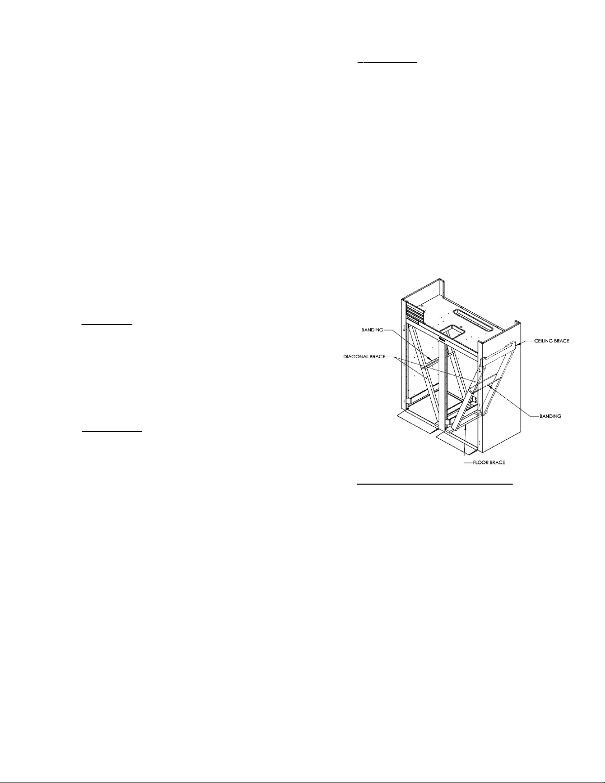
WARNING: Read and review these instructions, in their
entirety, BEFORE attempting to disassemble and remove
the interior bracing. If either of the diagonal or upper
ceiling braces are dropped, they could cause personal
injury or damage to the equipment.
To disassemble the bracing, first open the doors and
carefully remove the banding that holds the two
diagonal braces together.
WARNING: The diagonal braces will now be loose and
can fall out of position and possibly permit the ceiling
corner brace to fall.
Carefull remove one diagonal brace while supporting the
ceiling corner brace, so that it does not fall (see figure
1). Next, remove the ceiling brace, the remaining
diagonal brace, and lastly the floor brace - then discard.
Repeat as necessary for each section of the unit.
III. b - PACKAGING:
All Traulsen units are shipped from the factory bolted to
a sturdy wooden pallet and packaged in a durable
cardboard container. The carton is attached to the
wooden skid with the use of large staples. These should
first be removed to avoid scratching the unit when
lifting off the crate.
Most exterior stainless steel surfaces have a protective
vinyl covering to prevent scratching during
manufacturing, shipping and installation. After the unit
is installed in place of service, remove and discard the
covering from all surfaces.
To remove the wooden pallet, first if at all possible, we
suggest that the cabinet remain bolted to the pallet
during all transportation to the point of final installation.
The bolts can then be removed with a 3/4” socket
wrench. Avoid laying the unit on its front, side or back
for removal of the pallet.
NOTE: Traulsen does not recommend laying the unit
down on its front, side or back. However, if you must
please be certain to allow the unit to remain in an
upright position afterwards for 24 hours before plugging
it in so that the compressor oils and refrigerant may
settle.
Roll-Thru models also include special interior wood
bracing, intended to protect the cabinet during shipment.
This bracing should under no circumstances be removed
prior to the unit being installed in its final location.
Fig. 1
III. c - INSTALLING LEGS OR CASTERS:
6” high stainless steel legs are supplied standard for all
Traulsen reach-in and pass-thru units. Casters in lieu
of legs are available as an optional accessory for the
same models. These are shipped from the factory
packed inside a cardboard box which is strapped to one
of the shelves. Remove the nylon strap and open the
box, it should contain either four (4) legs or four (4)
casters and sixteen (16) bolts.
WARNING: THE CABINET MUST BE BLOCKED AND
STABLE BEFORE INSTALLING LEGS OR CASTERS.
To install the legs or casters, first raise and block the
reach-in a minimum of 7” from the floor. For
installing legs, thread the legs into the threaded holes
on the bottom of the cabinet (see figure 2). Be certain
that all legs are tightly secured (legs and casters should
be tightened to 300 inch/pounds, max). When the unit
is set in its final position, it is important for proper operation that the unit be level. The legs are adjustable for
this purpose, turn the bottom of the leg counterclockwise to raise it, clockwise to lower it. Level the
unit from front to back as well as side to side in this
manner, using a level placed in the bottom of the
-2-
cabinet.
III. INSTALLATION (continued)
III. c - INSTALLING LEGS OR CASTERS (cont’d):
Fig. 2
Please note that Traulsen units are not designed to be
moved while on legs. If the unit requires moving, a
pallet jack or forklift should be used to prevent damage.
For installing casters, the casters are “plate” type, and
require the use of four (4) bolts each to secure them
firmly to the cabinet bottom at each corner (see figure
3). The caster bolts are tightened using a 1/2” socket
wrench.
Threaded Holes
Fig. 3
Caster
III. d - SHELF PINS:
The unit is supplied with shelves and shelf pins installed.
Check all shelf pins to assure they are tightened down
as they may have come loose during shipping. Rotate
the pins clockwise until they are secured against the
side of the cabinet.
III. e - ROLL-IN MODEL INSTALLATION:
Roll-In cabinets set on the floor require the floor area to
be flat and level. In addition, after the cabinet is set in
place, sealant should be used around the perimeter of
the base to comply with National Sanitation Foundation
requirements (see figure 4). After sealing the unit, the
enclosed ramp should then be installed.
III. e - ROLL-IN MODEL INSTALLATION (cont’d):
facilitate rolling in racks. It is shipped wrapped in brown
paper and secured to the rack guides inside the
cabinet. To secure it in place, remove the two thumb
screws in the breaker strip near the bottom door
opening. Next, loosen the thumb screws located along
the floor at the threshold. Place the ramp(s) on top of
the loosened thumb screws and secure tabs on each
end to breaker strips with thumb screws previously
removed. After installing the ramp(s), it too should be
sealed to the floor.
Bumper strips are secured to the back of Roll-In models
with thumb screws. Loosen these and make them
finger tight to conform with the requirements of the
National Sanitation Foundation (NSF).
III. f -
ATTACHING DOUBLE DEPTH UNITS TOGETHER:
Double depth roll-in/roll-thru units are shipped as two
separate components which must be attached together
at the jobsite. To accomplish this, first, place the front
and rear cabinets in close proximity to each other being
careful to align the drain from the front of the rear unit
to the drain of the front unit. It will be necessary to level
both units together at this time.
Next, using two pipe clamps, pull the units together (see
figure 5). Install the covers over the gap formed between
the units From inside the cabinets, using the screws
provided, install the breaker strips using the strip as a
template.
Fig. 5 - Using two pipe
clamps, pull the two
units together and using
the screws provided.
Align the breaker strips
as a template for the
screw pattern inside and
outside the cabinet.
SEALING BASE OF ROLL-IN MODELS
A SEALANT MUST BE USED
AROUND THE PERIMETER OF THE
BASE OF CABINET AS SHOWN TO
FULLY COMPLY WITH SANITARY REQUIREMENTS.
A RECOMMENDED SEALANT IS
DOW CORNING SILASTIC RTV #732
Fig. 4
A stainless steel threshold ramp(s) is included to
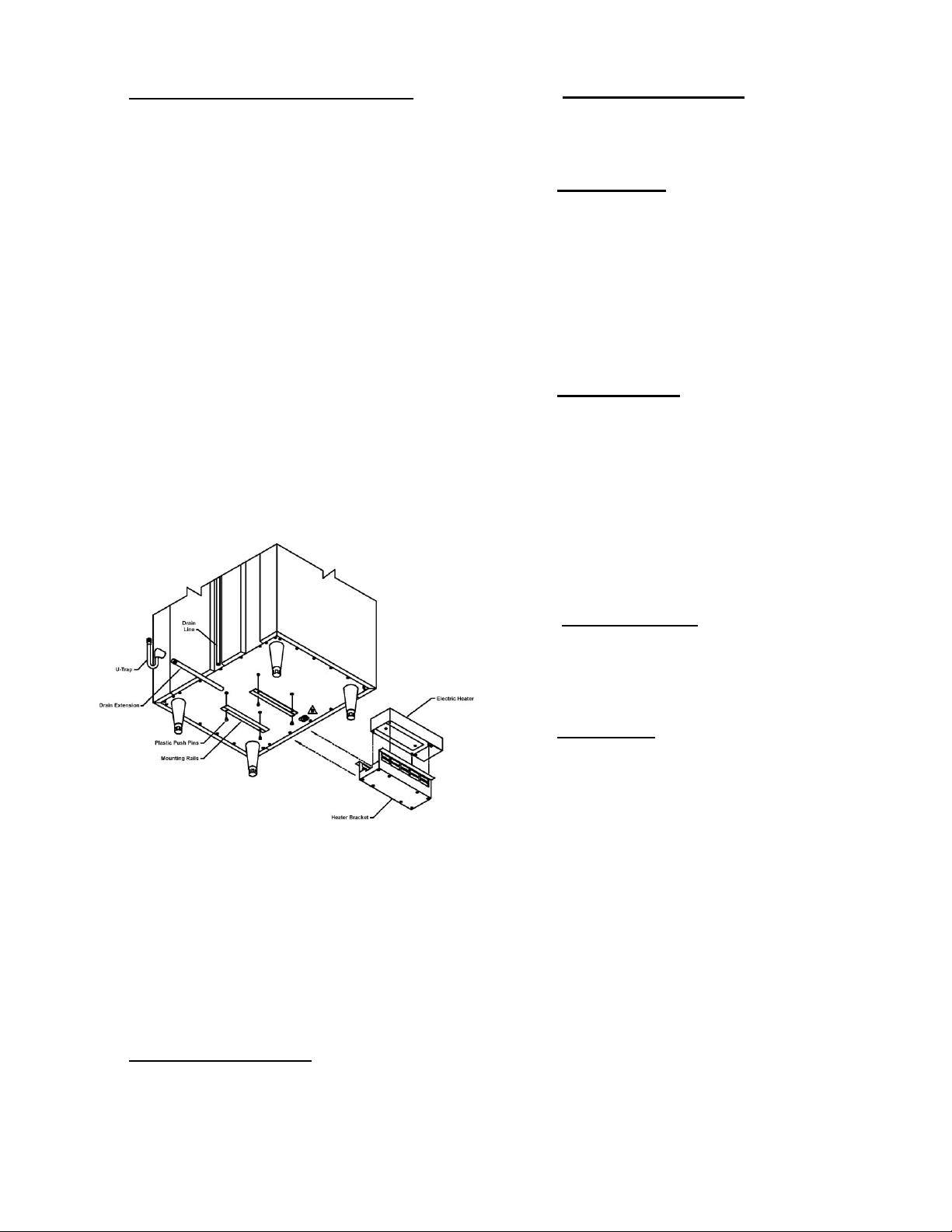
III. g - INSTALLING THE CONDENSATE EVAPORATOR:
A condensate evaporator is normally supplied on all
self-contained models (remote models require provision
of either a floor drain or an optional electric condensate
evaporator). On those models supplied with a
top-mounted evaporator coil compartment, the
condensate evaporator is also secured to the top of the
cabinet. Check that the condensate pan is properly
located underneath the drain tube.
-3-
III. INSTALLATION (continued)
III. g - INSTALLING THE CONDENSATE EVAP (cont’d):
NOTE: Some models, such as single section dualtemperature refrigerator/freezers, are supplied with a
bottom-mounted electric condensate evaporator. This
is shipped in a cardboard carton secured to the cabinet
interior, and must be PROPERLY installed prior to use
(see instructions supplied with the condensate
evaporator).
After the cabinet has been uncrated and the legs/
casters attached, you must install the bottom-mounted
electric condensate evaporator. Locate the four (4) holes
on the exterior bottom towards the rear of the cabinet.
Then, using the four (4) plastic push pins provided, attach the mounting rails to the cabinet bottom (the end
flange is to be up and be facing towards the cabinet rear).
Next, place the heater into the heater bracket (note the
enclosed springs are only to be used when the heater is
placed on the floor). Slide heater and bracket into the
mounting rails. Plug the supplied cord into both the
heater on one end, and the electrical outlet provided on
the cabinet exterior bottom towards the front (see
figure 6). Screw the “U-Trap” on to the drain line
located on the rear of the cabinet and then screw the
drain extension into the “U-Trap.”
III. h - REMOTE INSTALLATION (cont’d):
must be done in accordance with good practice and
local regulations. See section “III. g” for information
concerning condensate removal for remote models.
III. i - CORD & PLUG:
Most self-contained models are supplied with a cord &
plug attached. It is shipped coiled at the top of the
cabinet, secured by a nylon strip. For your safety and
protection, all units supplied with a cord and plug
include a special three-prong grounding plug on the
service cord. Select only a dedicated electrical outlet with
grounding plug for power source. NOTE: Do not under
any circumstances, cut or remove the round grounding
prong from the plug, or use an extension cord.
III. j -
POWER SUPPLY:
The supply voltage should be checked prior to
connection to be certain that proper voltage for the
cabinet wiring is available (refer to the serial tag to
determine correct unit voltage). Make connections in
accordance with local electrical codes. Use qualified
electricians.
Use of a separate, dedicated circuit is required. Size
wiring to handle indicated load and provide necessary
overcurrent protector in circuit (see amperage
requirements on the unit’s serial tag).
Fig. 6
NOTE: The use of the “U-TRAP” supplied is required.
Failure to use this component may allow cold air to
migrate down the drain line, resulting in condensation
on the rear of the cabinet.
A remote model is normally supplied configured for
condensate to be run to a floor drain unless purchased
with a condensate evaporator. The installer is
responsible for making the required extension to the
floor drain in accordance with good practice and local
regulations.
III. h - REMOTE INSTALLATION:
Remote models are supplied without compressors,
solenoid valves, etc. The correct voltage, amp listing
and refrigerant are listed on the units serial tag. It is the
responsibility of the installer to specify and supply the
correct size compressor(s) based upon this information
and on-site requirements. Refrigerant line installation
III. k - WIRING DIAGRAM:
Refer to the wiring diagram for any service work
performed on the unit. Should you require one, please
contact Traulsen Service at (800) 825-8220, and provide
the model and serial number of the unit involved.
III. l - CLEARANCE:
In order to assure optimum performance, the
condensing unit of your Traulsen unit MUST have an
adequate supply of air for cooling purposes. Therefore,
the operating location must either have a minimum of
12” clearance overhead of the condensing unit or allow
for unrestricted air flow at the back of the unit.
Clearance of at least 12” above is required in order to
perform certain maintenance tasks.
-4-
IV. OPERATION
IV. a - REFRIGERATORS:
Both refrigerators and freezers do not require manual
defrosting. During normal operation, a refrigerator
continuosly circulates above freezing cabinet air through
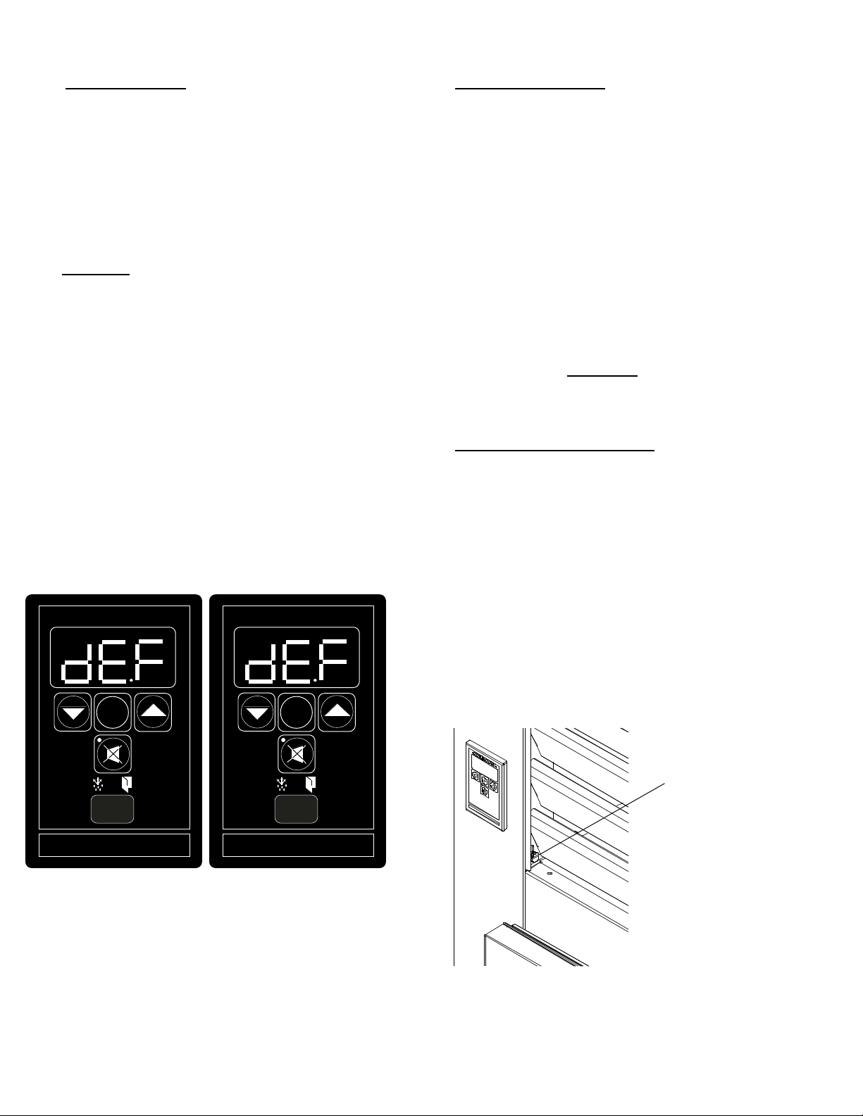
the coil. A compressor “OFF” cycle occurs
every hour to
melt any frost which may accumulate on the coil during the
compressor “ON” cycle. The control will read “dEF” when
this occurs and the evaporator fans will continue to operate.
With standard holding refrigerators, high relative humidity is
also maintained to prevent dehydration of stored product.
IV. b -
FREEZERS:
During normal operation, a freezer continuously circulates
below freezing cabinet air through the coil. The coil requires a
IV. c- HOT FOOD CABINETS:
Hot food cabinet operation is governed by the
INTELA-TRAUL control, which controls the ON/OFF
operation of the strip heaters. The control can bet set to
maintain any operational temperature between 140 - 180
F (in 5°F increments).
Hot food cabinets are delivered from the factory with
the control set to the “OFF” position. Follow the
instructions in section “VII. t” to get started.
NOTE: A vent is included at the top of all hot food
cabinets. The vent opening is factory set and secured
for best position. Be certain to make sure this vent is
kept free of any obstruction.
periodic defrosting for proper operation. This is accomplished
by an automatic, time activated, temperature/time terminated,
defrost program. The controller is preset at the factory for six
equally spaced defrost cycles within each 24-hour period.
At the start of a freezer defrost cycle, both the compressor
and evaporator fans are OFF. The INTELA-TRAUL® control will
read “dEF” (see figure 7). The electric heater (attached to the
coil) is energized. When a temperature device affixed to the
coil senses 70°F (models with electric defrost), the coil is fully
defrosted and the compressor operation is resumed, defrost
heaters are automatically turned off. The coil fans are delayed
from starting at the termination of a defrost cycle. Fan
operation is automatically resumed, or they can also be started
by a time or temp delay (whichever comes first). In case of
temp delay, it uses the same coil sensor and starts at 32°F.
The total refrigeration system operation is then resumed.
V. a - CLEANING THE CONDENSER:
The most important thing you can do to insure a long,
reliable service life for your Traulsen is to regularly clean
the condenser coil.
The condensing unit requires regularly scheduled
cleaning to keep the finned condenser clean of lint and
dust accummulation. The INTELA-TRAUL control will
notify you through a “CLN-FIL” message when
cleaning is necessary (see page 8). Keeping the
condenser clean allows the cabinet to operate more
INTELA-TRAUL
°F °C
INTELA-TRAUL
°F °C
efficiently and use less energy.
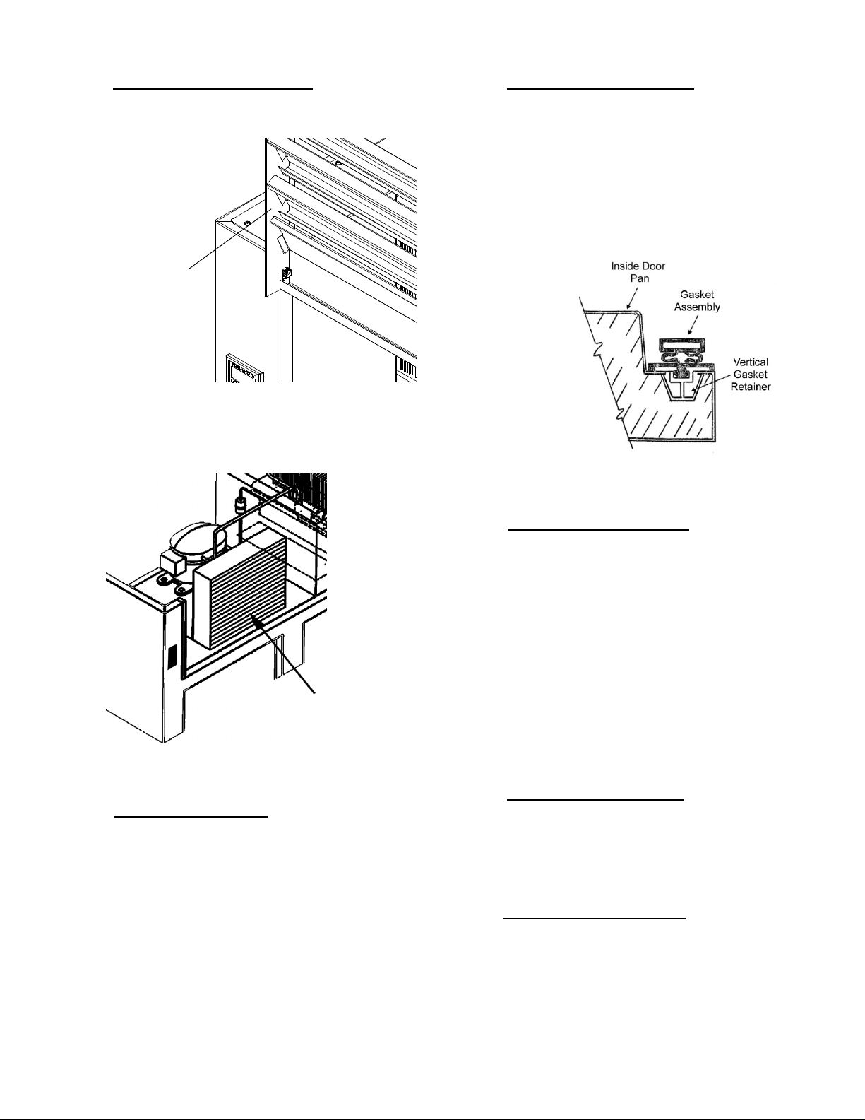
To clean the condenser, first disconnect electrical power
to the cabinet and lift up the front louver assembly. To
lift this, remove the two screws located on both sides at
the bottom of the louver assembly (see figure 8).
SET
SET
°
V. CARE & MAINTENANCE
WARNING
DISCONNECT ELECTRICAL POWER SUPPLY
BEFORE CLEANING ANY PARTS OF THE UNIT
)
)
)
REFRIGERATOR
FREEZER
Fig. 7
FREEZER
FREEZER
)
)
)
During freezer defrost operation, heat is confined to the coil
enclosure to prevent any significant rise in temperature within
the food zone. The fan delay controls function upon
termination of a defrost cycle is two-fold. First, to prevent
blowing warm air into the food storage area. Second, to
prevent any condensation on the defrost coil from being blown
into the food storage area.
The INTELA-TRAUL® control is set from the factory to
terminate defrost at 20 minutes in the event of a sensor
failure. This setting should never be tampered with, without
first consulting the factory.
-5-
Fig. 8
Remove
Screws
V. CARE & MAINTENANCE (cont’d)
V. a - CLEANING THE CONDENSER:
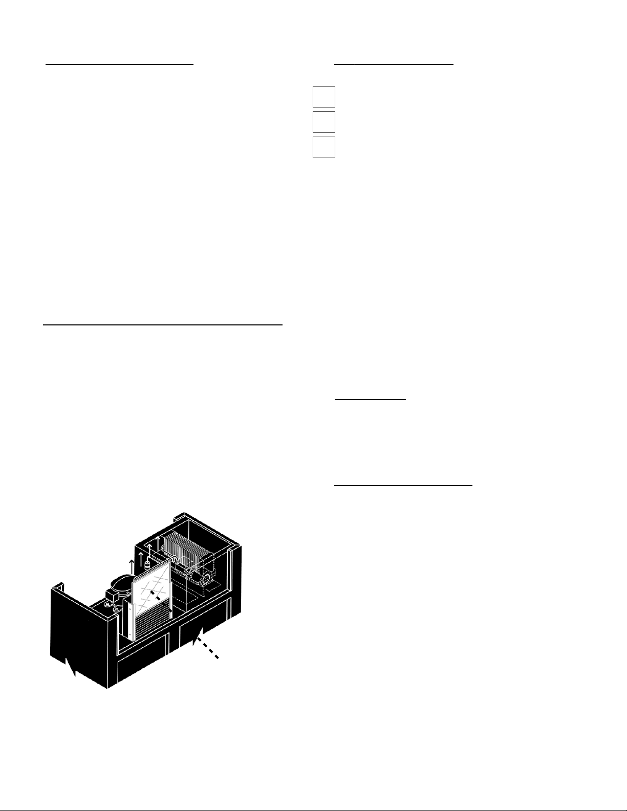
Once the screws are removed, the panel can be pivoted
upwards allowing full access to the front facing
condenser (see figure 9).
Fig. 7
Lift-Up Louver
Assembly
Vacuum or brush any dirt, lint or dust from the finned
condenser coil, the compressor and other cooling
system parts (see figure 10). If significant dirt is
clogging the condenser fins, use compressed air to
blow this clear.
V. c - REPLACING THE GASKETS:
To remove the gasket to be replaced, grasp it firmly by
one corner and pull it out. Before attempting to install a
new gasket, both the unit and the gasket itself must be
at room temperature. Insert the four corners first by
using a rubber mallet (or hammer with a block of wood).
After the corners are properly inserted, work your way
towards the center from both ends by gently hitting with
a mallet until the gasket is completely seated in place
(see figure 11 for proper gasket placement).
Fig. 11
NOTE: The gasket may appear too large, but if it is
installed as indicated above it will slip into place.
Fig. 10
Condenser
Surface
Lower louver assembly and replace the screws to hold
it in place.
V. b - HINGE REPLACEMENT:
Both the door and hinge can be easily removed from the
cabinet. To remove the door, remove the plug at the
bottom of the top hinge. Inside the hinge there is a small
screw which secures the door in place. Remove this
with a flat head screwdriver and the door can then be
lifted off the hinge. To remove the door portion of the
hinge from the door, lift off the hinge cover and then
remove the three Phillips head screws which secure the
hinge in place on the door. To remove the cabinet
portion of the hinge, remove the three Phillips head
screws which hold it in place. On solid door units, the
top hinge(s) contains a microswitch for controlling the
interior lighting.
To reassemble the hinge reverse the previous procedure.
V. d - CLEANING THE EXTERIOR:
Exterior stainless steel should be cleaned with warm
water, mild soap and a soft cloth. Apply with a
dampened cloth and wipe in the direction of the metal
grain.
Avoid the use of strong detergents and gritty, abrasive
cleaners as they may tend to mar and scratch the
surface. Do NOT use cleansers containing chlorine, this
may promote corrosion of the stainless steel.
Care should also be taken to avoid splashing the unit
with water, containing chlorinated cleansers, when
mopping the floor around the unit.
For stubborn odor spills, use baking soda and water
(mixed to a 1 TBSP baking soda to 1 pint water ratio).
V. e - CLEANING THE INTERIOR:
For cleaning both stainless steel and anodized
aluminum interiors, the use of baking soda as described
in section “V. d” is recommended. Use on breaker strips
as well as door gaskets. All interior fittings are
removable without tools to facilitate cleaning.
V. f - ADJUSTING THE SHELVES:
For shelves mounted on pins, first select the desired
location and remove the white plastic covers in the
interior back and sides by rotating them counterclockwise. Remove the shelf pins by rotating them
counter- clockwise. Install the pins in the desired
location by rotating clockwise. Make sure the pin is
securely tightened down. Do not over tighten. Slide the
shelf into its new position, and replace the white plastic
covers into the holes vacated by the shelf pins.
-6-
V. CARE & MAINTENANCE (cont’d) VI. OTHER
V. g - REPLACING THE LIGHT BULB:
All Traulsen R & A Series models are supplied with
incandecent lighting unless optional fluorescent
lighting was ordered (except for sliding glass door
models for which fluorescent lights are supplied
standard).
The bulb is a 115 volt/40 watt, T-61⁄2 intermediate clear
refrigerator lamp. It is mounted at the top front of the
cabinet at the center, and is located behind a plastic light
cover on refrigerator and freezer model.
Heated units (RHF/AHF/RIH/AIH/RDH/ADH/RIDH/AIDH)
are equipped with a similar type bulb, however this is
shatterproof because these models do not include a
plastic light cover.
To replace the bulb, first remove the light cover (if so
equipped). This can be accomplished by squeezing it
together on both sides until it comes free. Replace the
light bulb, then squeeze both sides of the light cover
together and replace in its original position.
V. h - REPLACING THE OPTIONAL CONDENSER FILTER:
Some Traulsen R & A Series models are supplied with
an optional filter screen for the condenser coil. This is
located behind the louver assembly, and must be cleaned
at least once a month, or more frequently if needed, to
insure proper equipment operation.
To clean the condenser filter, first disconnect electrical
power to the cabinet and lift up the front louver
assembly. To lift this, remove the two screws located
on both sides at the bottom of the louver assembly. The
filter is located on the face of the condenser coil, and
can simply lifts up and away for cleaning (see figure 12).
VI. a - SERVICE INFORMATION:
Before calling for service, please check the following:
Is the electrical cord plugged in?
Is the fuse OK or circuit breaker on?
Is the power switch “ON”?
If after checking the above items and the unit is still not
operating properly, please contact an authorized
Traulsen service agent. A complete list of authorized
service agents was provided along with your Traulsen
unit. If you cannot locate this, you may also obtain the
name of a service agent from the Service/Contact page
of our website: www.traulsen.com.
If service is not satisfactory, please contact our in-house
service department at:
Traulsen
4401 Blue Mound Road
Fort Worth, TX 76106
(800) 825-8220
Traulsen reserves the right to change specifications or
discontinue models without notice.
VI. b - SPARE PARTS:
Spare or replacement parts may be obtained through a
parts supplier or one of our authorized service agents.
A complete list of authorized service agents
accompanies this manual and is also posted on our
company’s official website @ www.traulsen.com.
Fig. 12
VI. c - WARRANTY REGISTRATION:
For your convenience, the warranties on your new
Traulsen unit may be registered with us on-line at
www.traulsen.com, or by completing and returning the
warranty card included along with the unit. To do so online, from the menu at the top of the home page, first
select PRODUCT SUPPORT. Upon loading that page,
select WARRANTY INFO from the menu on the left. A
link to the WARRANTY REGISTRATION FORM should
appear. Click on this to load the form, complete the
required information, and hit the SUBMIT button.
Filter
-7-
VII. The INTELA-TRAUL® Control System
Your new Traulsen Refrigerator, Freezer or Hot Food cabinet is equipped with a state-of-the-
®
art electronic microprocessor INTELA-TRAUL
control, which precisely regulates operation
and provides alarms when problems occur. It is supplied from the factory completely ready
for use and requires no adjustment (except Hot Food units which are set in the “OFF”
position, see page for 20 for more info), but without the audible alarms activated. See pages
9 thru 20 for more information.
VII. a - INTELA-TRAUL® CONTROL FEATURES:
1- Internal Time Clock
• Eliminates defrost time clock (refrigerator and freezer models only).
• Defrost cycle can be quickly adjusted to suit individual location and use.
• Must be set at power-up.
• Will automatically update for Daylight Savings Time.
2- Water Resistant Housing - The face of the control is water resistant to provide for protection during cleaning.
3- Parameter/Service Levels
• See “Customer / Service Parameters” on Page 11.
4- Defrost Lockouts - See “Setting Defrost Lockouts” on page 17 (refrigerator and freezer models only).
• Customers can set up to 4 different defrost lockout periods. The lockout prevents the unit from going into a defrost cycle
during peak kitchen use. Note: The 24-hour clock must be set for this feature to operate correctly.
5- Communication Ability - A NAFEM Data Protocol (NDP) compliant RS-485 serial communications port is available to
interface with data collection software (by others). All INTELA-TRAUL equipped models are capable of communicating
within a NAFEM Data Protocol network if provided with an optional Gateway Hub (available from Traulsen). The actual
communications software is available from a number of third party software vendors.
6- Anti-Condensate Door Perimeter Heater Control (refrigerator and freezer models only)
“No-Sweat” feature is an energy savings system that allows the customer to set the percent of time for the door heater as
needed for the prevailing ambient conditions (from 0 - 100% of the time each day). It is used to prevent condensation from
forming around the perimeter of the doors.
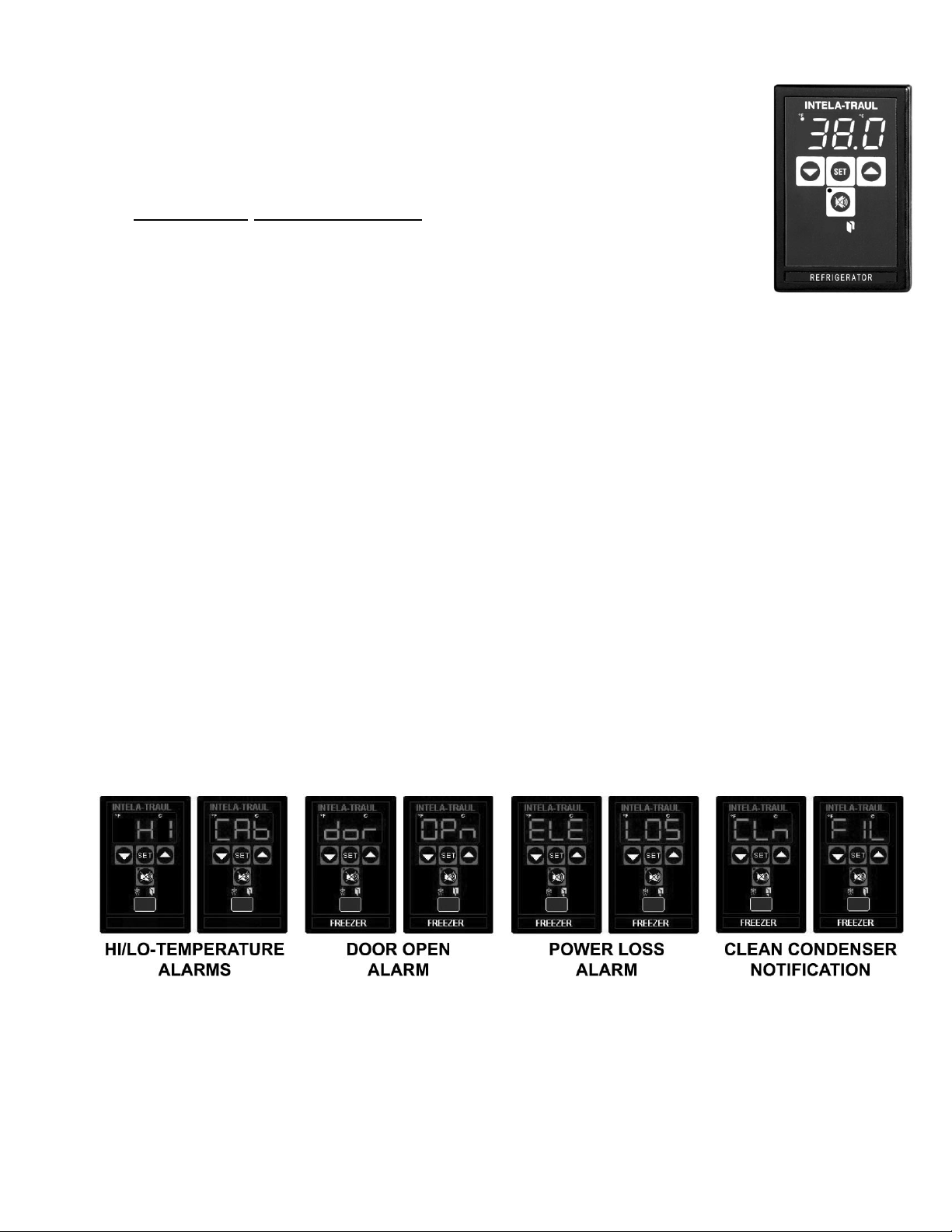
7- Alarms (See the following pages for explanations)
• High Cabinet Air Temperature • System Leak (refrigerator, freezer & dual-temp models only)*
• Low Cabinet Air Temperature • Door Open**
• Loss Of Power • Clean Condenser (refrigerator and freezer models only)*
• Sensor Failure
* Not Available On Remote Models
8- Display Features
** Not Available On Fire-Rated Or Sliding Glass Door Models
• Door Open Icon
• 3-Digit LED Display
• Defrost in Progress Icon
• Fahrenheit or Celsius Temperature Scale In Use
-8-
 Loading...