


REAR CAMERA
INSTALLATION MANUAL
PZQ90-89011
HILUX
August 2011 Production Onwards
Installation Time Approximately 60 minutes
For August 2013 production vehicle onward requires
PZQ60-00230 harness (to be ordered separately)
Ver 5.0 10/2015

Page of 2/68
Introduction
WARNING!
Describes precautions that should be observed in order to prevent injury or death to the user during installation
CAUTION!
Describes precautions that should be observed in order to prevent damage to the vehicle or its components, which
may occur during installation of insufficient care is taken
NOTE
Provides additional information that facilitates installation work.
FRONT, REAR, LEFT, RIGHT
Shows the direction when viewed from the driver’s seat.
IMPORTANT
Describes the procedure that must be strictly followed to ensure correct operation of the system, durability and
safety to the end user.
Important Notice
This manual has been designed for technicians who are qualified and educated in the proper procedures of vehicle
safety, handling and maintenance; experienced in installation of navigation systems or who are cable to carry out
installation procedures when given instructions by an experienced technician in a supervisory capacity.
1. If a problem is found with the rear camera due to installation, refer back to the manual to correct the problem (s).
2. Vehicle and rear camera kit components as well as installation procedures are subject to change without prior
notice. Refer to the latest installation manual and service information. Any changes affecting the above items will
be given in the form of “Installation instructions for the system (supplement)” (issued by Fujitsu Ten) or a Service
Bulletin (issued by Toyota).
Definition of Term
IMPORTANT SAFETY PRECAUTIONS AND PROCEDURES FOR INSTALLER
The following precautions and procedures must be carried out when installing the system to ensure long term
durability, correct operation and safety for the end user.
All wiring must be positioned where it will not interfere with the vehicle operation or systems.
All wiring must be firmly secured using cable ties (supplied).
Cable ties must be positioned at 300mm intervals maximum.
Wiring must not be attached to moving components or position over sharp edges or vehicle components
that may wear and jam or damage wiring.
Excess wiring from antenna and main wiring harness must be bundled at a safe location to ensure no
interference with vehicle operation / systems.
All nuts, bolts and screws removed to carry out the installation of the system must be re-installed to original
vehicle specification and torque values as specified in the applicable Toyota Repair Manual.
© FUJITSU TEN AUSTRALIA PTY LTD
89 COOK STREET, PORT MELBOURNE 3207, VIC
All rights reserved. This book may not be reproduced or copied, in whole or in part, with the written permission of the publisher.
A.C.N. 63 007 413 578
Page of 3/68
Table of Contents
No
Description
Page
1
System Parts
4
2
Part Removals and Installation for Hilux Single Cab (Aug 2015 production onward)
5-12
3
Part Removals and Installation for Hilux Double Cab (Aug 2015 production onward)
13-21
4
Part Removals and Installation for Hilux Double Cab (Aug 2015 production onward)
22-30
5
Part Removals and Installation for Hilux Single Cab (Aug 2011- Jul 2015 production)
31-41
6
Part Removals and Installation for Hilux Extra Cab (Aug 2011- Jul 2015 production)
42-53
7
Part Removals and Installation for Hilux Double Cab (Aug 2011- Jul 2015 production)
54-65
8
Rear Camera Connection
66
9
Rear Camera View Adjustment for vehicles with tub
67
10
Reinstallation
68
11
Owner’s Manual and Caution Label
68
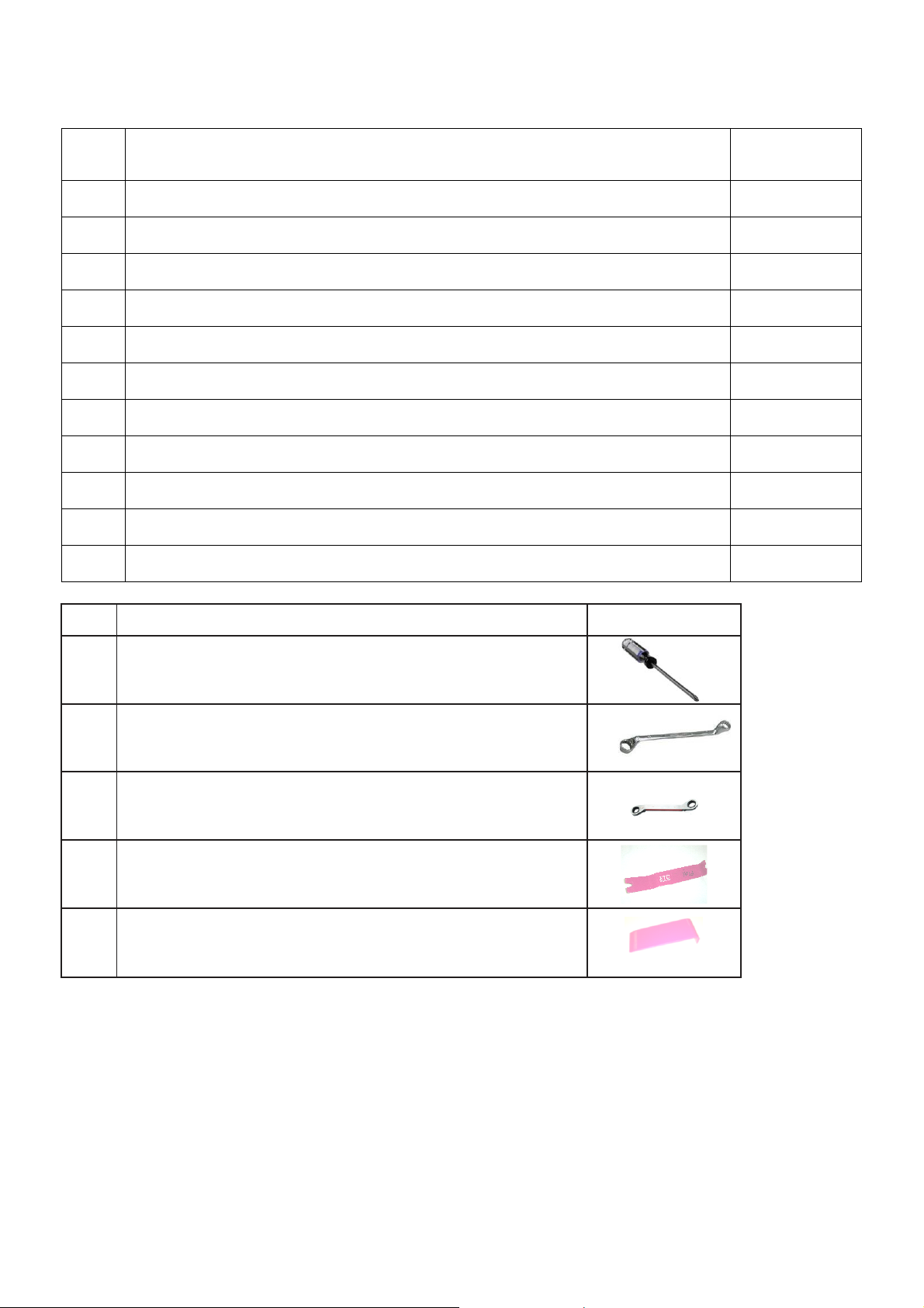
No
Description
Images
1
Phillips head screw driver (size 1 and 2)
2
Ring spanner size (7mm, 10mm and 14mm)
3
Ratchet size 7mm
4
Clip removal tool
5
Trim removal tool
Page of 4/68
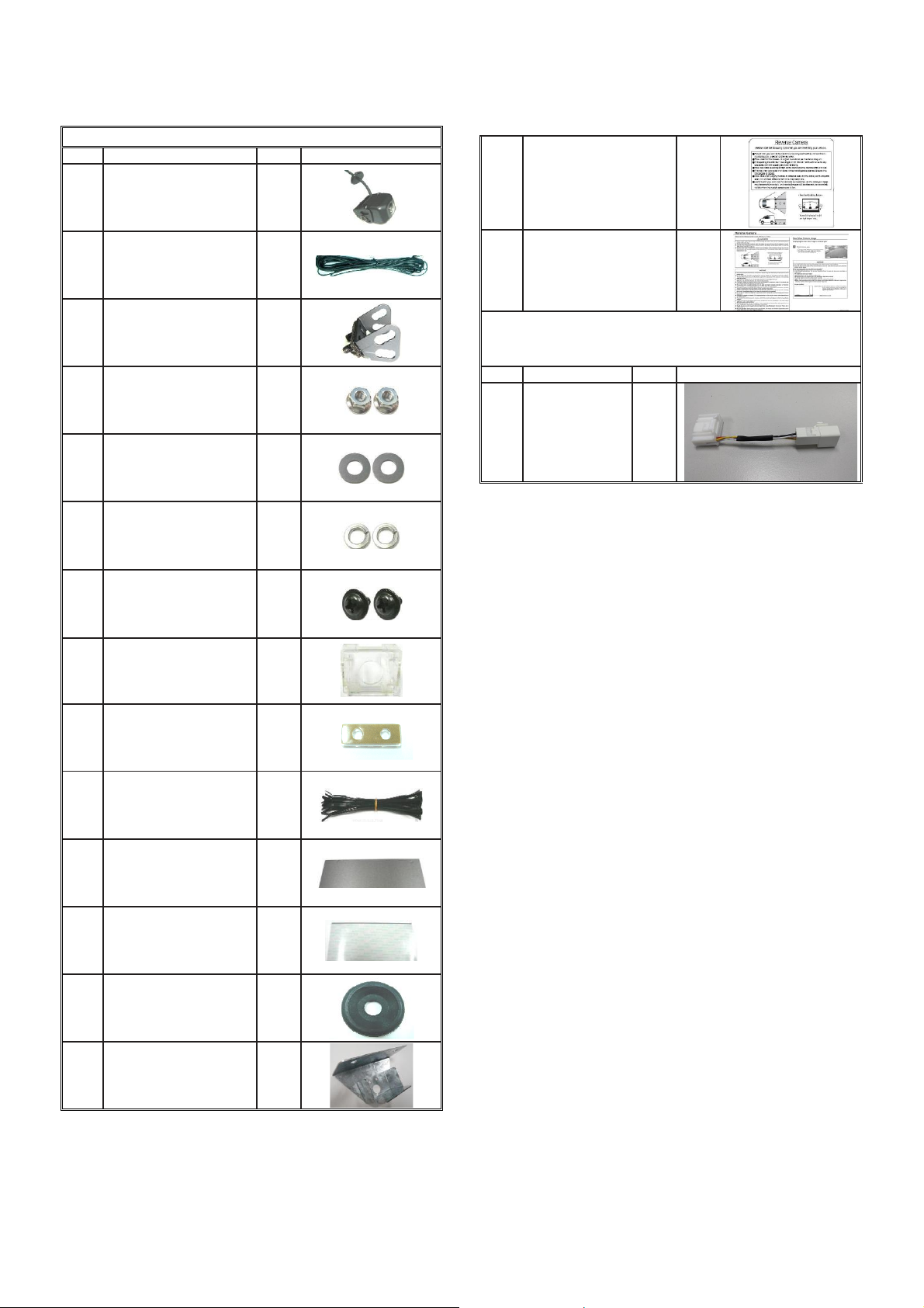
1. System Parts
Hilux Rear Camera Kit (PZQ90-89011)
No
Description
Qty
Images
1
Rear Camera
1 2
Rear camera harness
1 3
Camera Bracket
1
4
M4 nuts
2
5
M4 Washers
2 6
M4 Spring washers
2
7
M3x6 bolts
2
8
Angle adjustment jig
1
9
Drilling jig
1 10
Cable tie
20 11
Wire harness tape
5 12
Protection tape
1
13
Camera additional
grommet
1
14
Tray body bracket
1
15
Caution Label
1
16
Owner’s manual
1
Hilux Camera Patch Wire Harness (PZQ60-00230)
(Supplied separately, only for 2013 production
onward vehicle)
No
Description
Qty.
Images
1
Patch Harness
1
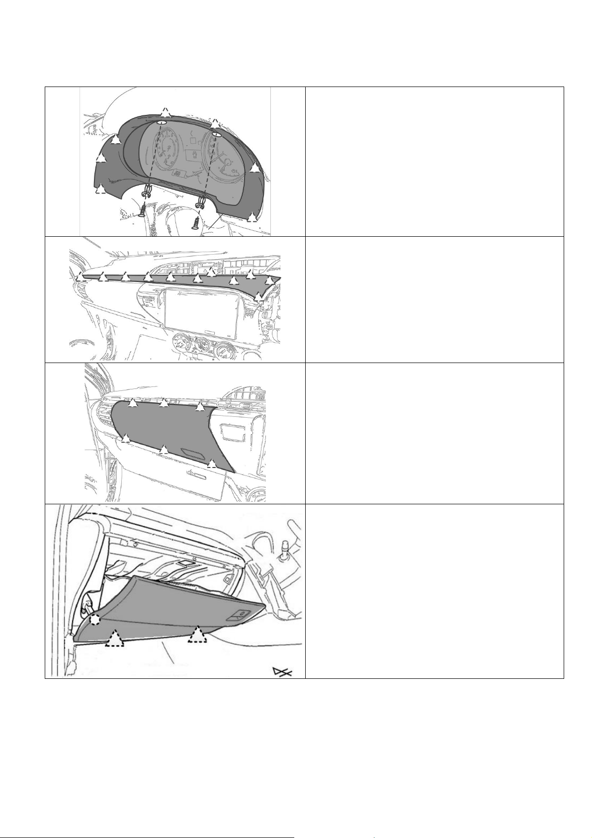
2. Part Removals and Installation for Single Cab (August 2015
CAUTION
Remove negative terminal of battery before proceeding
with installation. Have all temporarily removed parts
stored in a safe location where no damage can occur.
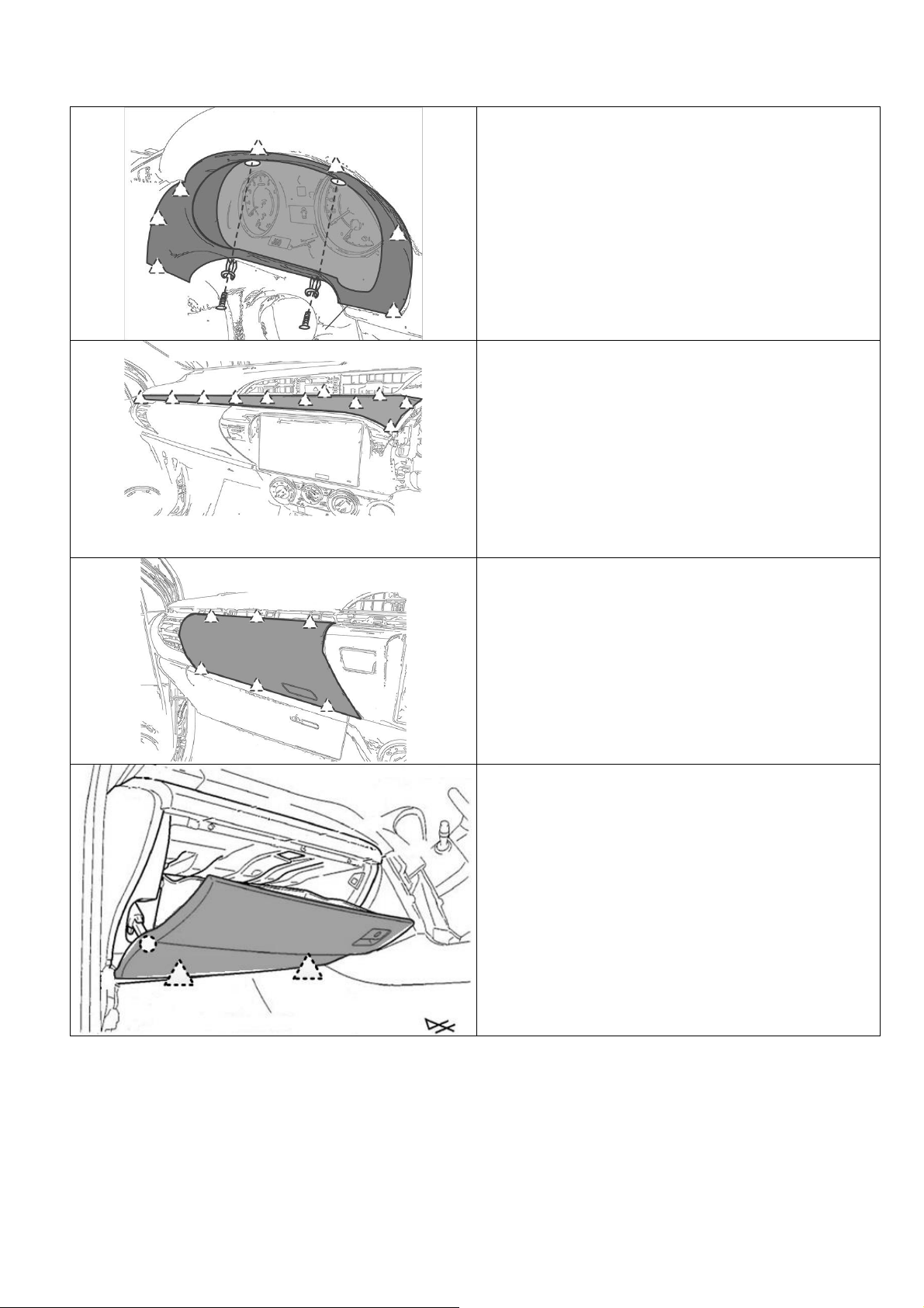
STEP 1. Remove the plastic screws and push in type
clips. Then remove the combi meter panel as shown.
STEP 2. Remove the upper trim panel as shown.
STEP 3. Remove the panel box as shown.
STEP 4. Remove the glove box by first detaching
damper on the left and then pulling outwards as shown.
Production Onward)
Page 5/68
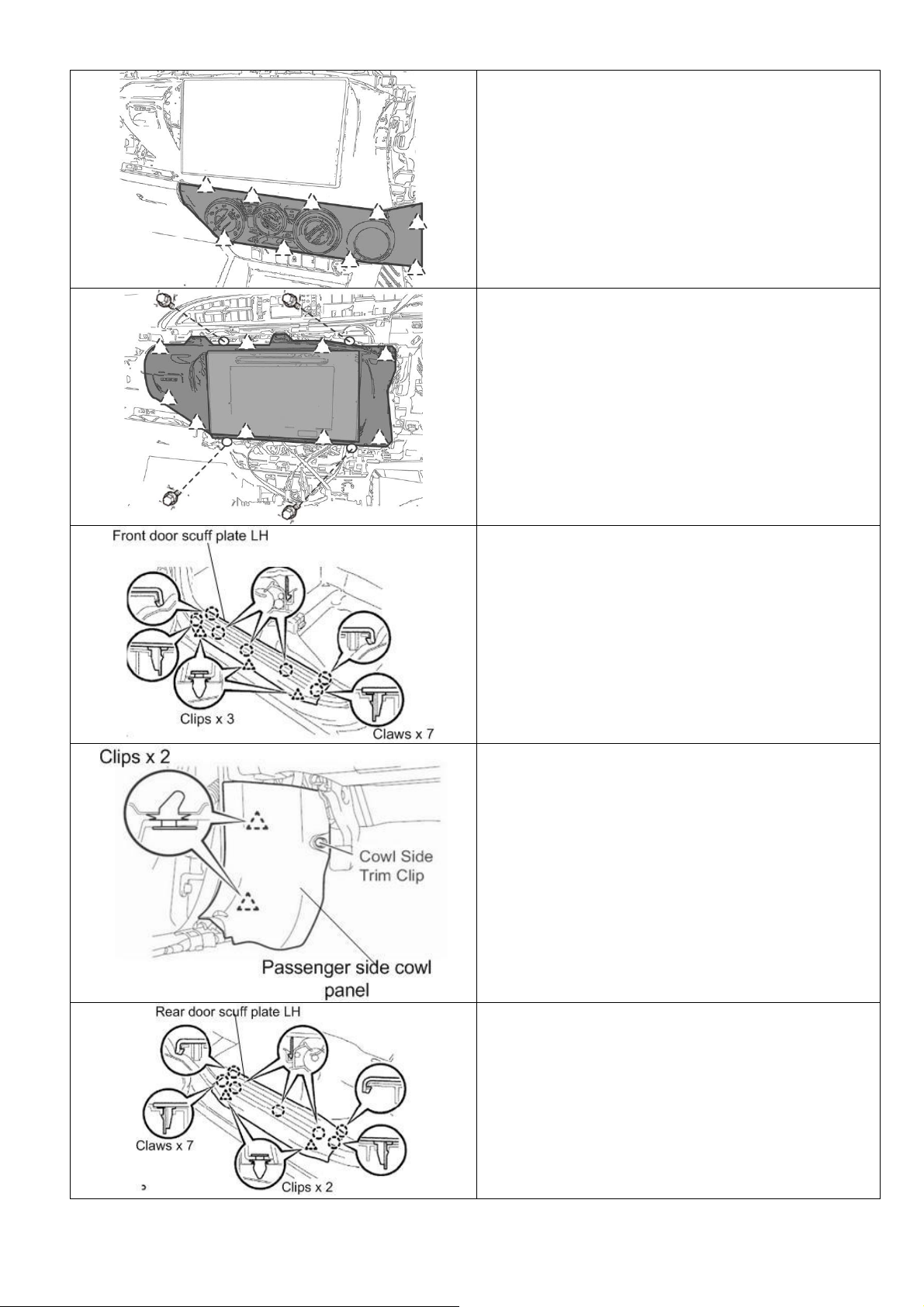
STEP 5. Remove heater control panel.
CAUTION!
Make sure not to pull or damage the attached heat
control wire. Rest the heater control making sure that the
facia is not damaged.
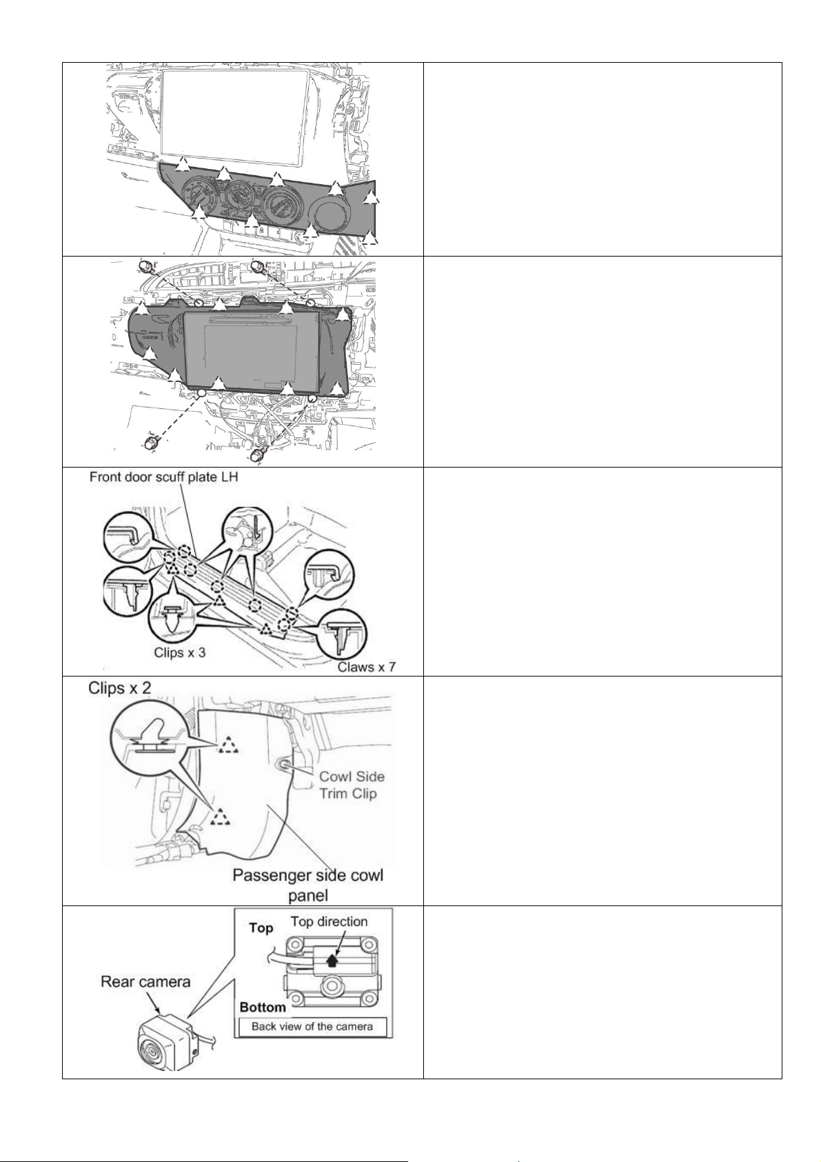
STEP 6. Remove the audio unit and surround panel
assembly as shown.
CAUTION!
Audio unit and surround panel are attached together.
Please remove the audio with surround panel all
together.
STEP 7. Remove door scuff plate LH as shown.
STEP 8. Remove the left hand side cowl panel as shown
STEP 9. Set the rear camera for the bracket installation.
Check the back of the camera and see the arrow mark
and set the camera as shown.
Page 6/68
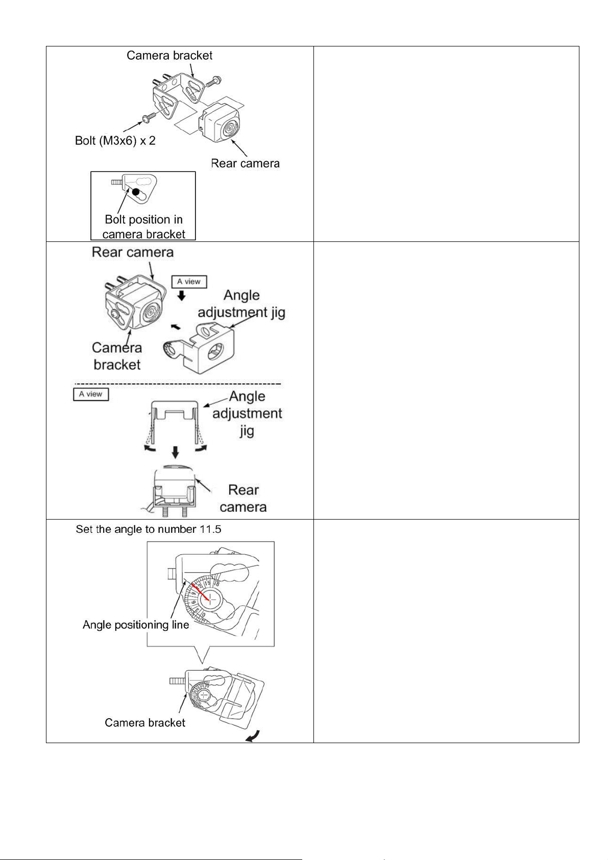
STEP 10. Install the rear camera to the camera bracket
as shown.
STEP 11. Install the angle adjustment jig, to adjust the
rear camera angle.
STEP 12. Adjust the camera angle to number 11.5 of the
angle adjustment jig as shown. When the angle is set,
tighten the bolt of the camera.
IMPORTANT:
When fitting the camera bracket, torque the bolts to 1Nm.
Page 7/68
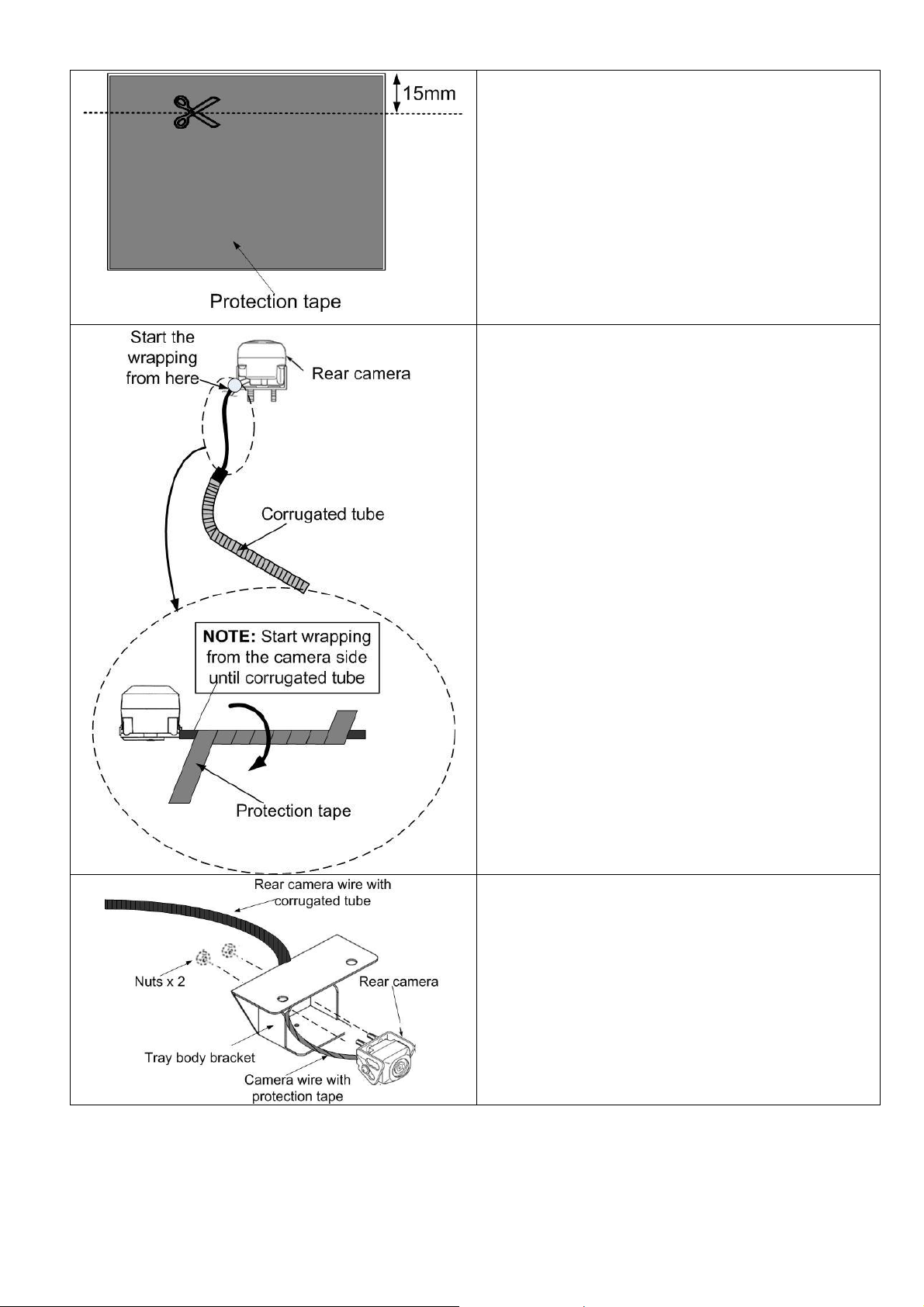
STEP 13. Take the supplied protection tape and then cut
about 15mm wide of the tape as shown.
STEP 14. Apply the protection tape to the rear camera
wire until the corrugated tube as shown.
NOTE:
1) Make sure to wrap the camera wire start from the
wire on the camera side as shown.
2) Make sure that all camera wire is wrapped until
the corrugated tube.
STEP 15. Pass the camera wire through the bracket hole
as shown and then install the rear camera using the
supplied nuts as shown.
IMPORTANT:
When fitting the camera to the bracket, torque the nuts to
3Nm.
Page 8/68
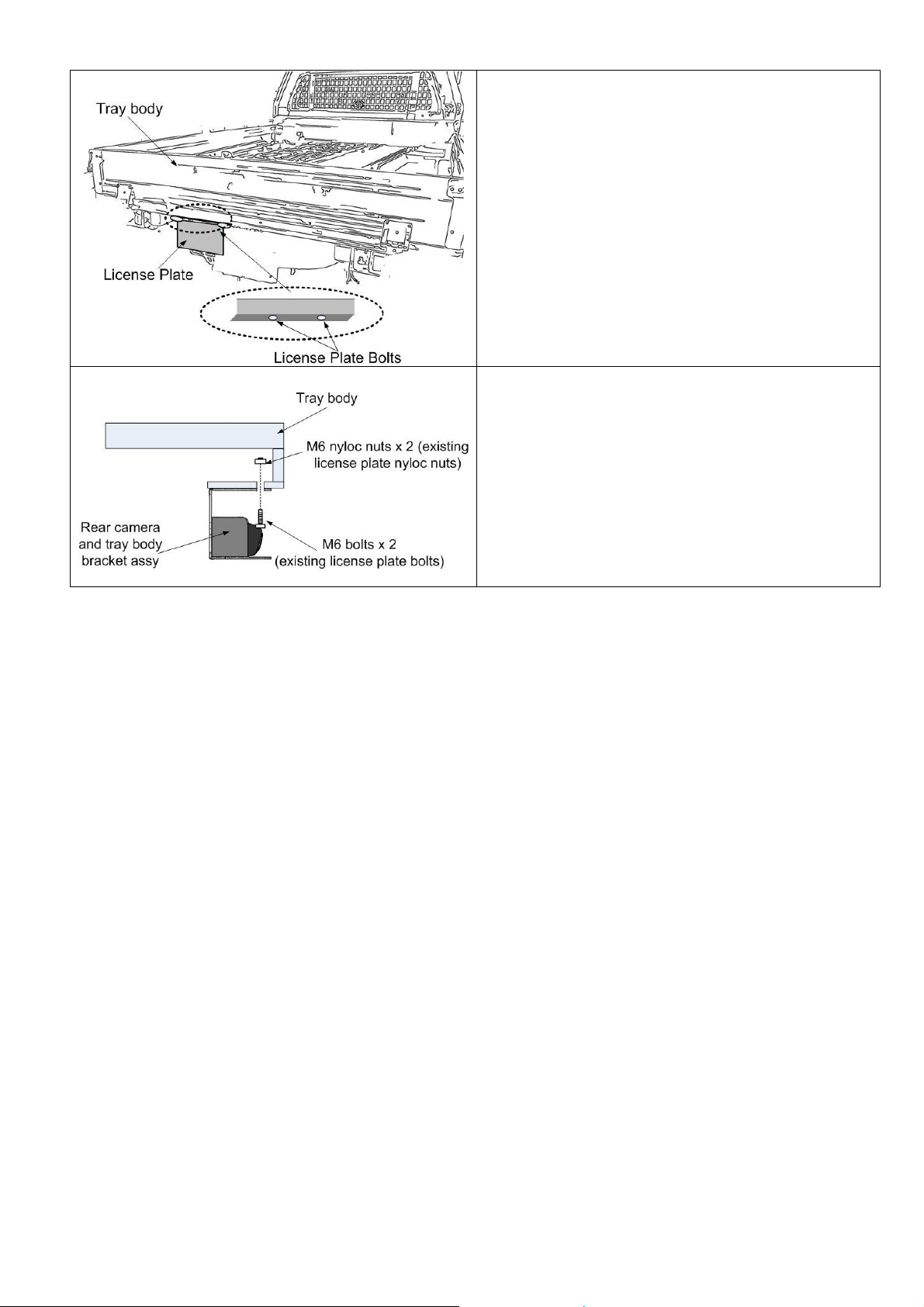
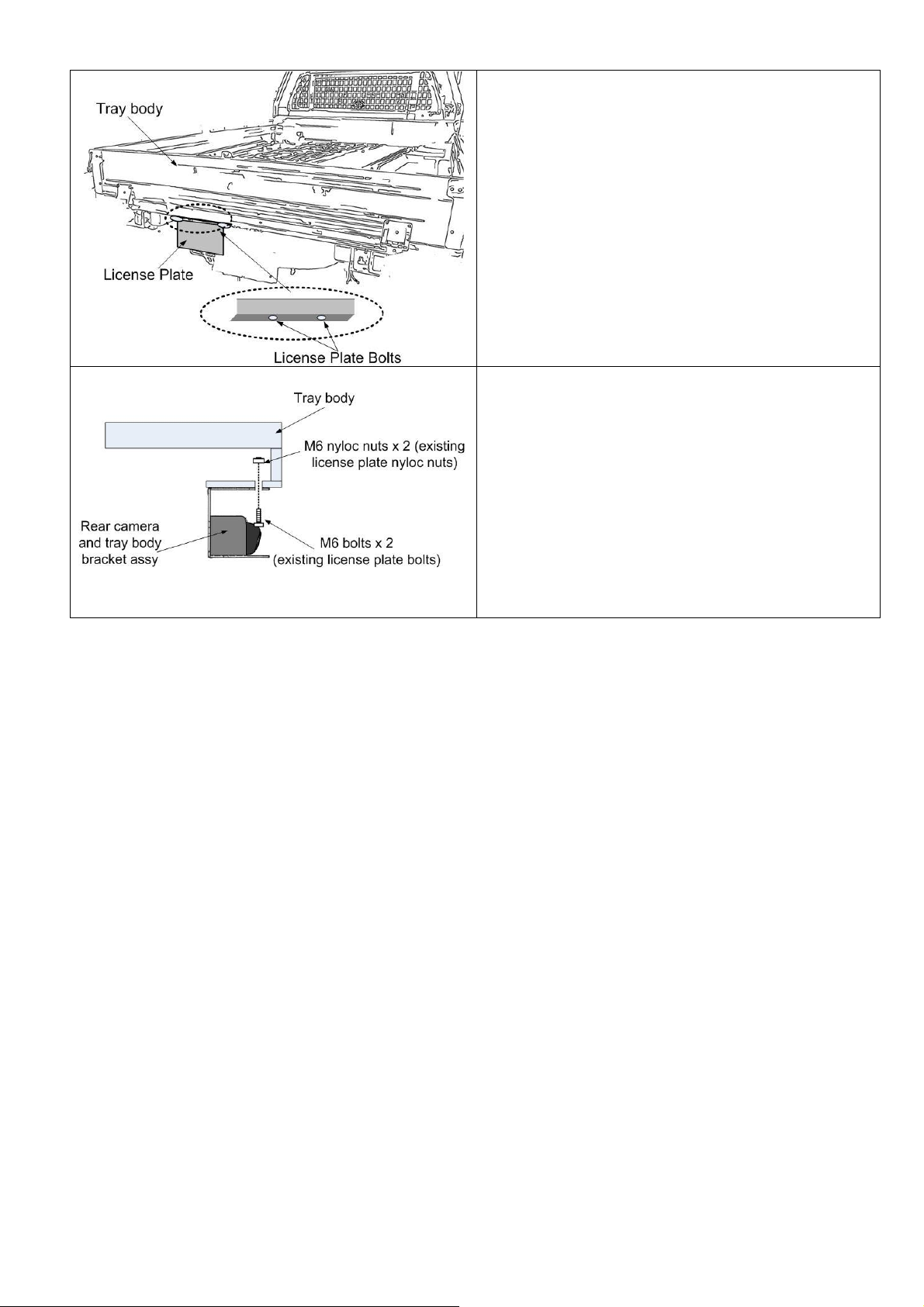
STEP 16. Locate the license plate bolts as shown,
remove the bolts and the nyloc nuts and then re-use both
bolts and nyloc nuts for rear camera bracket installation.
STEP 17. Install the rear camera and tray body bracket
assembly to the trail body position hole using the existing
license plate M6 bolts and M6 nyloc nuts.
IMPORTANT:
When fitting the tray body bracket to the tray, torque the
bolts to 7-11 Nm.
Page 9/68
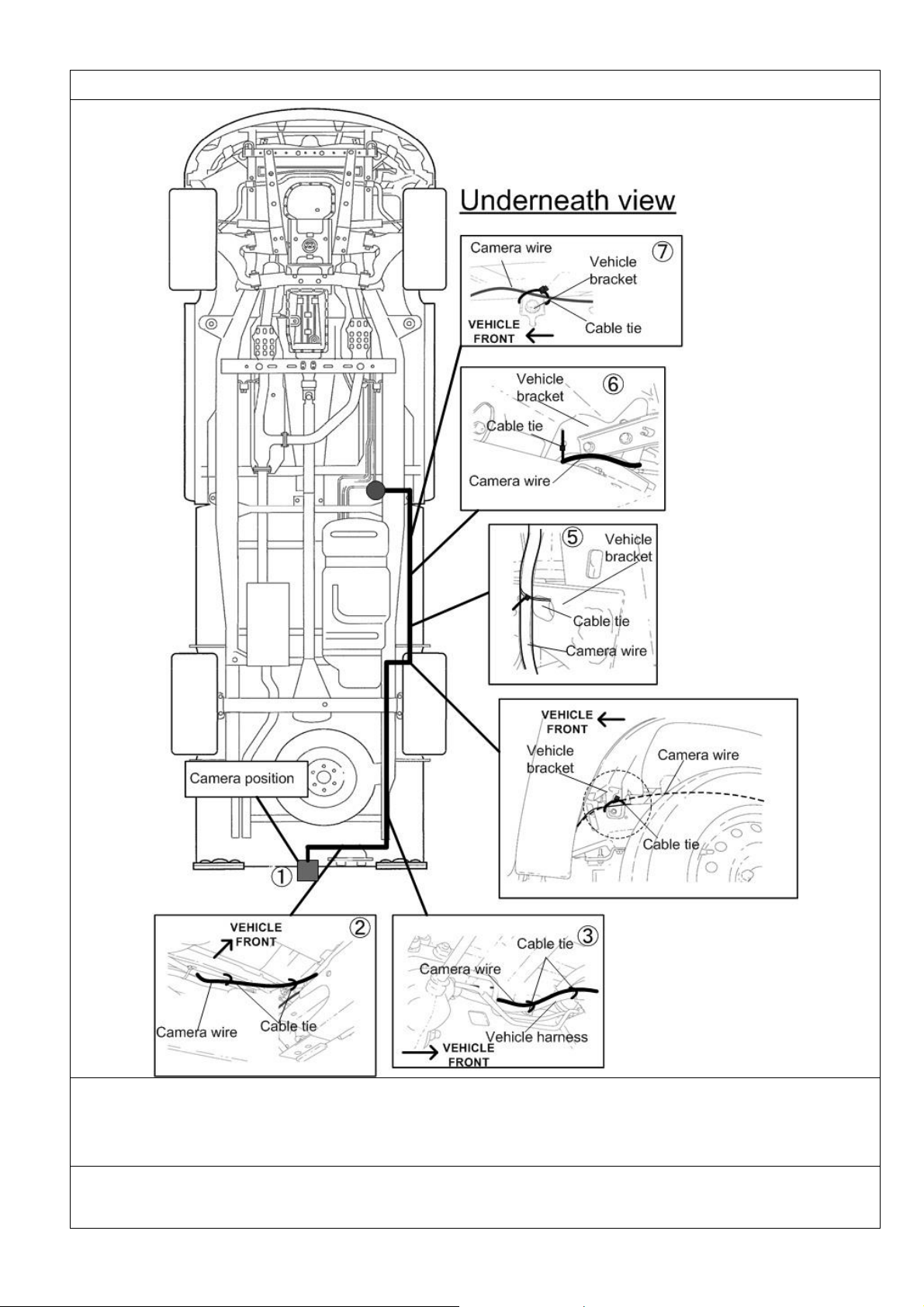
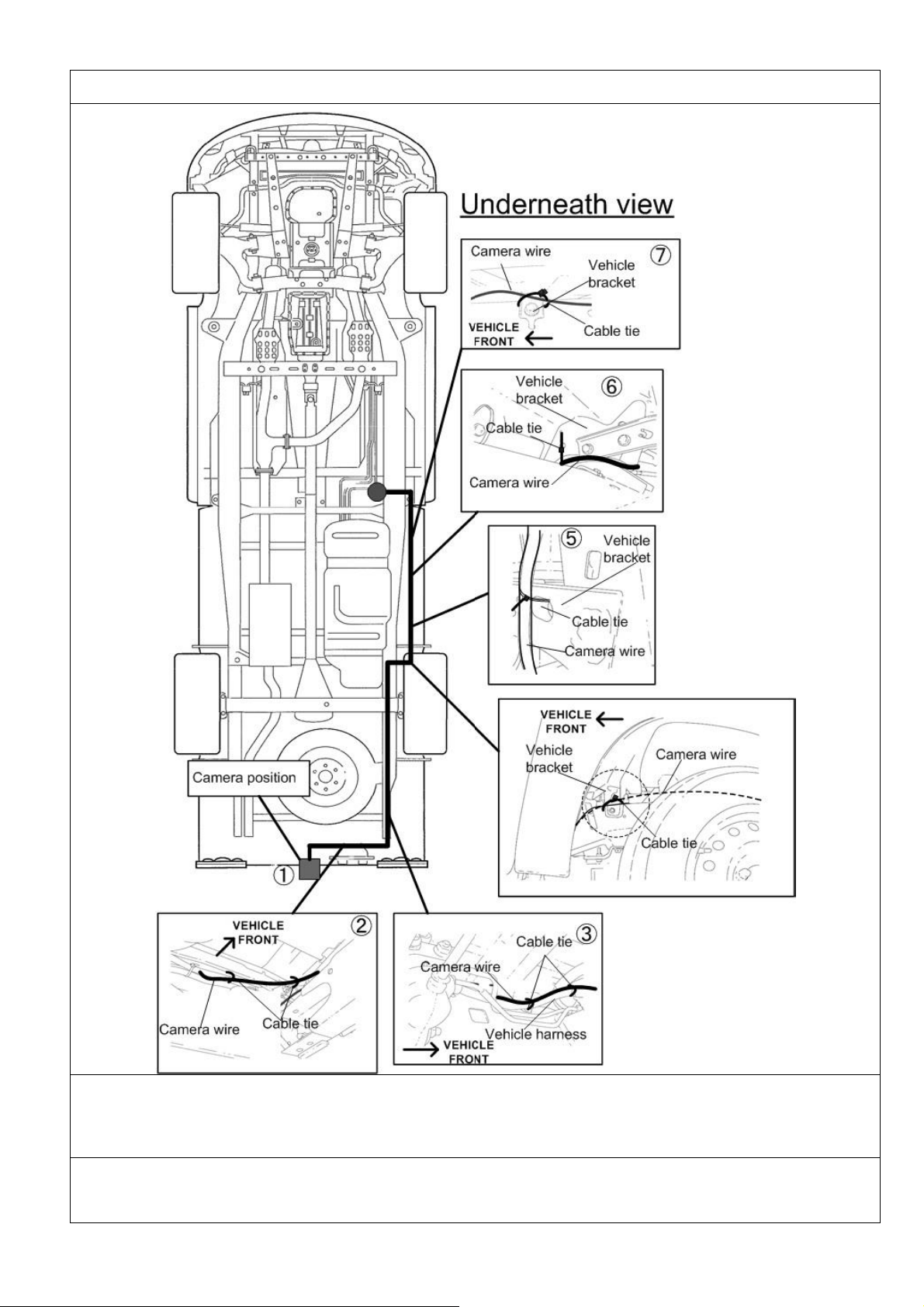
Rear Camera Outer Wiring
IMPORTANT:
Make sure that the wire does not come out of the corrugated tube at any instance. If there is a
possibility of wire coming out from the corrugated tube, apply tape over the corrugated tube after
pushing the wire into the tube.
(1)Temporarily install the camera using tape or similar at the location as shown on the drawing, and then route the
camera wire underneath the vehicle, (2), (3). Follow the existing vehicle harness and then cable tie it, (3), (4), (5), (6),
and (7). Route the wire near the rear left wheel and then cable tie it to the existing vehicle brackets.
Page 10/68
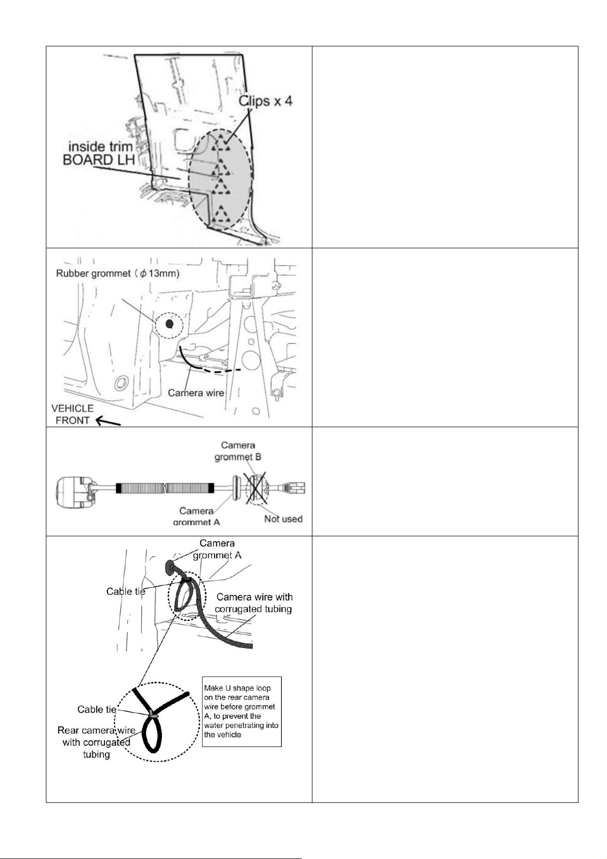
STEP 18. Loosen half of the inside trim board LH by
unclipping the area shown to expose the grommet.
STEP 19. Locate the vehicle rubber grommet (φ13mm)
on the left hand side back of the vehicle. Remove the
vehicle rubber grommet and discard.
STEP 20. Cut and discard grommet B (the grommet
close to the inter-connector).
STEP 21. Pass through the camera inter-connector to the
vehicle grommet hole and install camera grommet to the
grommet hole as shown.
Just in front of the camera grommet, make U shape loop
on the rear camera wire, to prevent the water penetrating
into the vehicle.
CAUTION
- Make sure that the rear camera wire loop is
facing down all the time.
- Make sure that the camera wire loop is outside
the vehicle all the time.
Page 11/68
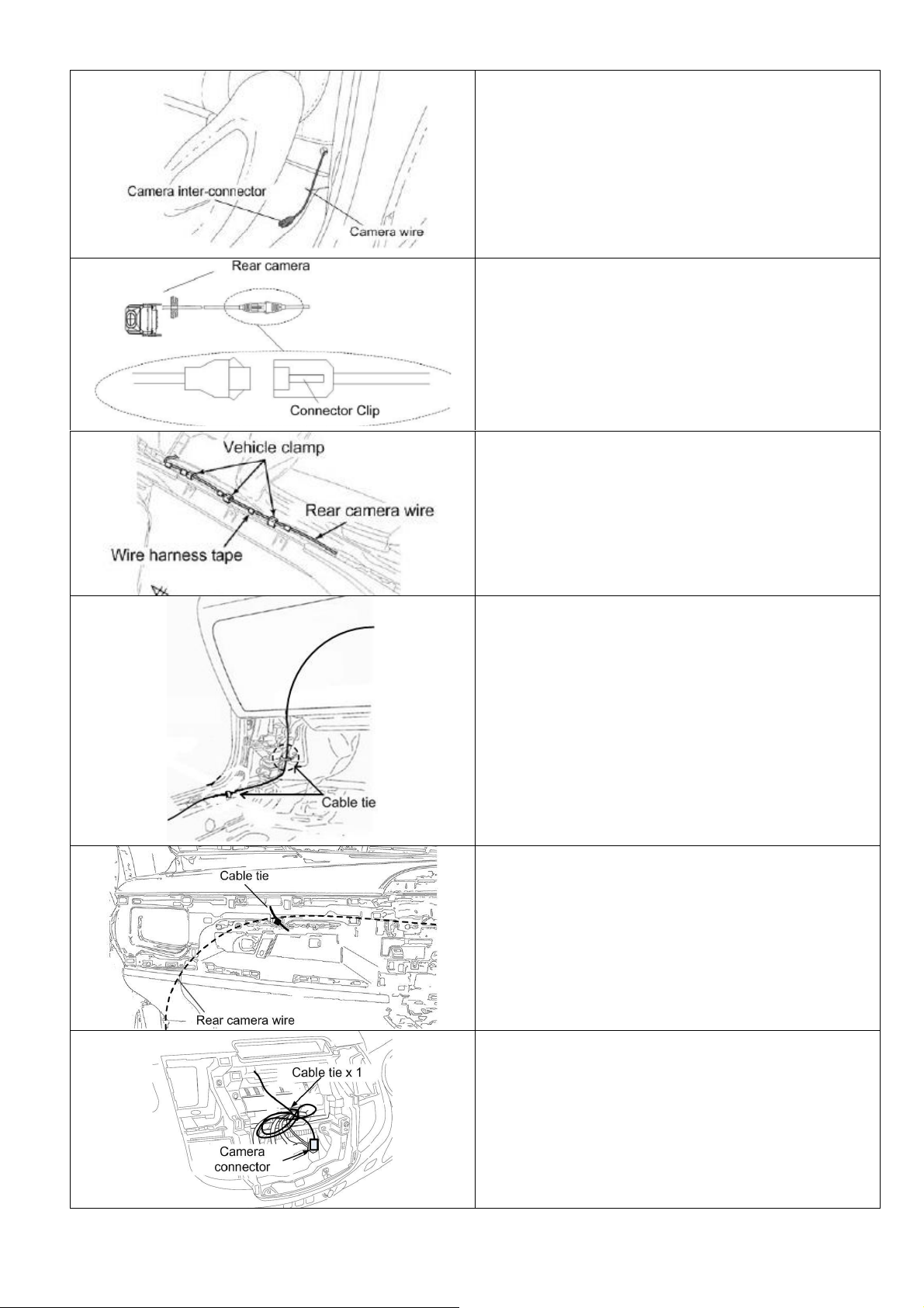
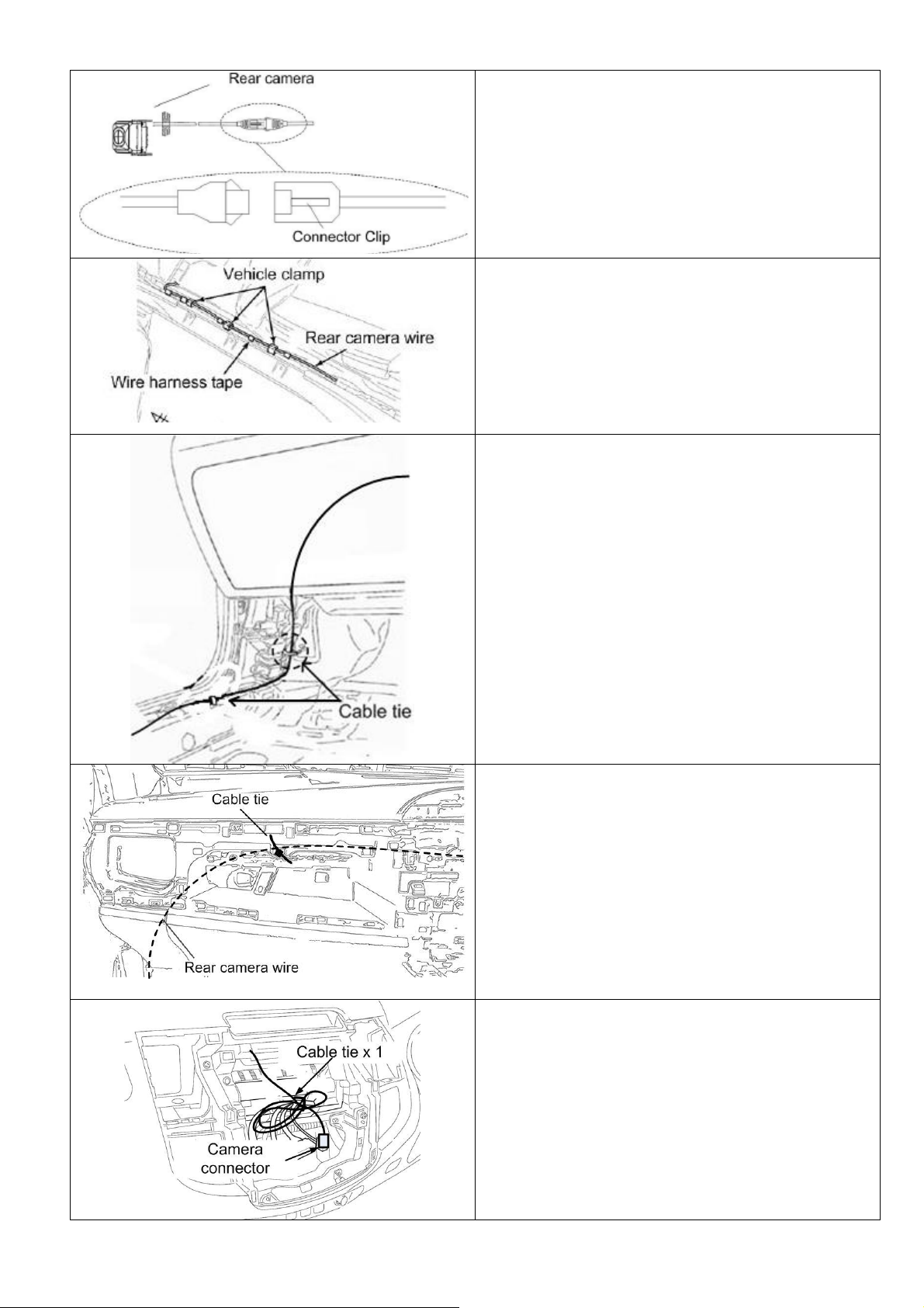
STEP 22. Pull the camera inter-connector from the back
seat area as shown.
STEP 23. Connect the camera inter-connector as shown.
STEP 24. Route the camera wire as shown.
NOTE:
Cable tie at regular intervals of 200mm
STEP 25. Route the camera wire up to glove box area as
shown.
NOTE:
Cable tie at regular intervals of 200mm
STEP 30. Route the rear camera connector to the centre
console area.
NOTE:
Cable tie at regular intervals of 200mm
STEP 31. Cable tie the excess wire to the existing vehicle
harness
Go to page 66 to complete installation.
Page 12/68
3. Part Removals and Installation for Hilux Double Cab
CAUTION
Remove negative terminal of battery before proceeding
with installation. Have all temporarily removed parts
stored in a safe location where no damage can occur.
STEP 1. Remove the plastic screws and push in type
clips. Then remove the combi meter panel as shown.
STEP 2. Remove the upper trim panel as shown.
STEP 3. Remove the panel box as shown.
STEP 4. Remove the glove box by first detaching
damper on the left and then pulling outwards as shown.
Page 13/68
STEP 5. Remove heater control panel.
CAUTION!
Make sure not to pull or damage the attached heat
control wire. Rest the heater control making sure that the
facia is not damaged.
STEP 6. Remove the audio unit and surround panel
assembly as shown.
CAUTION!
Audio unit and surround panel are attached together.
Please remove the audio with surround panel all
together.
STEP 7. Remove door scuff plate LH as shown.
STEP 8. Remove the left hand side cowl panel as shown.
STEP 9. Remove the rear door scuff plate LH as shown.
Page 14/68
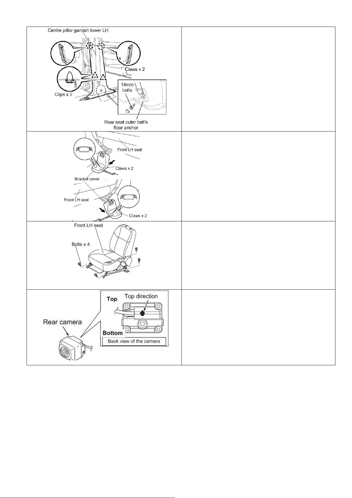
STEP 10. Remove the seat outer belt’s floor anchor. And
then remove the centre pillar garnish lower LH as shown.
IMPORTANT:
When re-fitting the seat belts, torque the bolts to 42Nm.
STEP 11. Remove the front LH seat bracket cover as
shown.
STEP 12. Remove the 4 bolts from the front LH seat as
shown. Move the LH seat slightly to the front, so the
vehicle carpet is moveable.
IMPORTANT:
When re-fitting the seat, torque the bolts to 37Nm.
CAUTION:
There is a passenger seat sensor wire under the seat.
The wire does not need to be removed.
STEP 13. Set the rear camera for the bracket
installation. Check the back of the camera and see the
arrow mark and set the camera as shown.
Page 15/68

STEP 14. Install the rear camera to the camera bracket
as shown.
STEP 15. Install the angle adjustment jig, to adjust the
rear camera angle.
STEP 16. Adjust the camera angle to number 11.5 of the
angle adjustment jig as shown. When the angle is set,
tighten the bolt of the camera.
IMPORTANT:
When fitting the camera bracket, torque the bolts to 1Nm.
Page 16/68

STEP 17. Take the supplied protection tape and then cut
about 15mm wide of the tape as shown.
STEP 18. Apply the protection tape to the rear camera
wire until the corrugated tube as shown.
NOTE:
1) Make sure to wrap the camera wire start from the
wire on the camera side as shown.
2) Make sure that all camera wire is wrapped until
the corrugated tube.
STEP 19. Pass the camera wire through the bracket hole
as shown and then install the rear camera using the
supplied nuts as shown.
IMPORTANT:
When fitting the camera to the bracket, torque the nuts to
3Nm.
Page 17/68
STEP 20. Locate the license plate bolts as shown,
remove the bolts and the nyloc nuts and then re-use both
bolts and nyloc nuts for rear camera bracket installation.
STEP 21. Install the rear camera and tray body bracket
assembly to the trail body position hole using the existing
license plate M6 bolts and M6 nyloc nuts.
IMPORTANT:
When fitting the tray body bracket to the tray, torque the
bolts to 7-11 Nm.
Page 18/68
Rear Camera Outer Wiring
IMPORTANT:
Make sure that the wire does not come out of the corrugated tube at any instance. If there is a
possibility of wire coming out from the corrugated tube, apply tape over the corrugated tube after
pushing the wire into the tube.
(1)Temporarily install the camera using tape or similar at the location as shown on the drawing, and then route the
camera wire underneath the vehicle. (2), (3) Follow the existing vehicle harness and then cable tie it. (3), (4), (5), (6),
(7) Route the wire near the rear left wheel and then cable tie it to the existing vehicle brackets.
Page 19/68

STEP 22. Cut and discard grommet B (the grommet
close to the inter-connector).
STEP 23. Install the camera grommet B (camera
grommet close to the camera inter-connector) to the
camera additional grommet (supplied) as shown.
NOTE:
Make sure that the lip of the smaller grommet is seated
firmly in the inner grove of the bigger grommet.
STEP 24. Cut and take away the excess corrugated tube
before installing the camera grommet to the vehicle.
NOTE:
Make sure that the camera wire at the outside of the
vehicle is covered with corrugated tube
STEP 25. Pass through the camera inter-connector to the
vehicle grommet hole and install camera grommet
assembly to the existing vehicle hole. Cable tie the rear
camera wire to the existing vehicle harness.
STEP 26. Pull up the vehicle carpet at the back of the
front LH seat as shown.
Grab and pull the camera inter-connector and then wire it
as shown.
Page 20/68
STEP 27. Connect the camera inter-connector as shown.
STEP 28. Route the camera wire as shown.
NOTE:
Cable tie at regular intervals of 200mm
STEP 29. Route the camera wire up to glove box area as
shown.
NOTE:
Cable tie at regular intervals of 200mm
STEP 30. Route the rear camera connector to the centre
console area.
NOTE:
Cable tie at regular intervals of 200mm
STEP 31. Cable tie the excess wire to the existing vehicle
harness
Go to page 66 to complete installation.
Page 21/68
 Loading...