

Toyota Camry 1994 User Manual
FOREWORD
This wiring diagram manual has been prepared to provide
information on the electrical system of the 1994 TOYOTA
CAMRY.
Applicable models: SXV10 Series
MCV10 Series
For service specifications and repair procedures of the above
models other than those listed in this manual, refer to the
following manuals;
Manual Name Pub. No.
1994 CAMRY Repair Manual
Volume 1
Volume 2
1994 Model New Car Features
RM361U1
RM361U2
NCF099U
All information in this manual is based on the latest product
information at the time of publication. However, specifications
and procedures are subject to change without notice.
TOYOTA MO TOR CORPORATION
NOTICE
When handling supplemental restraint system components (removal,
installation or inspection, etc.), always follow the direction given in the repair
manuals listed above to prevent accidents and supplemental restraint
system malfunction.
1

INTRODUCTION
A
This manual consists of the following 11 sections:
No.
INDEX Index of the contents of this manual.
INTRODUCTION Brief explanation of each section.
B
C
D ABBREVIATIONS Defines the abbreviations used in this manual.
E
HOW TO USE
THIS MANUAL
TROUBLE–
SHOOTING
GLOSSARY OF
TERMS AND
SYMBOLS
Section Description
Instructions on how to use this manual.
Describes the basic inspection procedures for electrical circuits.
Defines the symbols and functions of major parts.
F RELAY LOCATIONS
G
H
I
J GROUND POINTS Shows ground positions of all parts described in this manual.
ELECTRICAL
WIRING ROUTING
POWER SOURCE
(Current Flow Chart)
INDEX Index of the system circuits.
SYSTEM CIRCUITS
Shows position of the Electronic Control Unit, Relays, Relay Block, etc.
This section is closely related to the system circuit.
Describes position of Parts Connectors, Splice points, Ground points, etc.
This section is closely related to the system circuit.
Describes power distribution from the power supply to various electrical
loads.
Electrical circuits of each system are shown from the power supply through
ground points. Wiring connections and their positions are shown and
classified by code according to the connection method. (Refer to the
section, “How to use this manual”).
The “System Outline” and “Service Hints” useful for troubleshooting are
also contained in this section.
K
2
OVERALL
WIRING DIAGRAM
Provides circuit diagrams showing the circuit connections.

HOW TO USE THIS MANUAL
This manual provides information on the electrical circuits installed on vehicles by
dividing them into a circuit for each system.
The actual wiring of each system circuit is shown from the point where the power source
is received from the battery as far as each ground point. (All circuit diagrams are shown
with the switches in the OFF position.)
When troubleshooting any problem, first understand the operation of the circuit where
the problem was detected (see System Circuit section), the power source supplying
power to that circuit (see Power Source section), and the ground points (see Ground
Points section). See the System Outline to understand the circuit operation.
When the circuit operation is understood, begin troubleshooting of the problem circuit
to isolate the cause. Use Relay Location and Electrical Wire Routing sections to find
each part, junction block and wiring harness connectors, wiring harness and wiring
harness connectors, splice points, and ground points of each system circuit. Internal
wiring for each junction block is also provided for better understanding of connection
within a junction block.
Wiring related to each system is indicated in each system circuit by arrows (from
, to ). When o verall connections a re required, see the O verall Wiring Diagram
at the end of this manual.
3
HOW TO USE THIS MANUAL
* The system shown here is an EXAMPLE ONLY. I t i s different to the
actual circuit shown in the SYSTEM CIRCUITS SECTION.
4
: System Title
A
: Indicates a Relay Block. No shading is used and only
B
C
G
the Relay Block No. is shown to distinguish it from the
J/B.
Example: Indicates Relay Block No. 1.
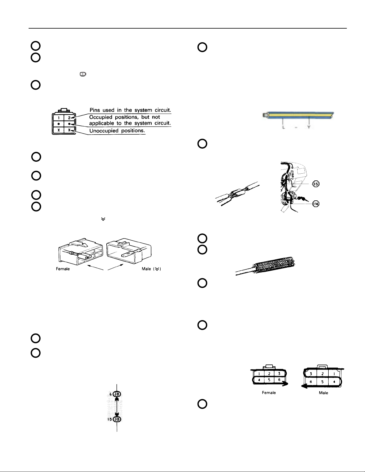
: Indicates the connector to be connected to a part (the
numeral indicates the pin No.)
Explanation of pin use.
The pins shown are only for the highest grade, or only
include those in the specification.
D
: Connector Color
Connectors not indicated are milky white in color.
E
: ( ) is used to indicate different wiring and connector,
etc. when the vehicle model, engine type, or
specification is different.
F
: Indicates related system.
: Indicates the wiring harness and wiring harness
connector. The wiring harness with male terminal is
shown with arrows ( ).
Outside numerals are pin numbers.
: Indicates the wiring color.
J
Wire colors are indicated by an alphabetical code.
B = Black L = Blue R = Red
BR = Brown LG = Light Green V = Violet
G = Green O = Orange W = White
GR = Gray P = Pink Y = Yellow
The first letter indicates the basic wire color and the
second letter indicates the color of the stripe.
Example: L – Y
(Blue) (Yellow)
: Indicates a wiring Splice Point (Codes are “E” for the
K
L
M
Engine Room, “I” for the Instrument Panel, and “B” for
the Body).
Example:
The Location of Splice Point I 5 is indicated by the
shaded section.
: Page No.
: Indicates a shielded cable.
The first letter of the code for each wiring harness and
wiring harness connector(s) indicates the component’s
location, e. g . , “ E ” f o r t h e Engine Compartment, “I” for the
Instrument Panel and Surrounding area, and “B” for the
Body and Surrounding area.
When more than one code has the first and second
letters in c o m m on, followed by numbers (e.g., IH1, IH2),
this indicates the same type of wiring harness and
wiring harness connector.
: Represents a part (all parts are shown in sky blue). The
H
code is the same as the code used in parts position.
I
: Junction Block (The number in the circle is the J/B No.
and the connector code is shown beside it). Junction
Blocks are shaded to clearly separate them from other
parts (different junction blocks are shaded differently for
further clarification).
Example:
3B indicates
that it is inside
Junction Block
No. 3.
: Indicates a ground point.
N
The first letter of the code for each ground point(s)
indicates the component’s location, e.g., “E” for the
Engine Compartment, “I” for the Instrument Panel and
Surrounding area, and “B” for the Body and
Surrounding area.
: Indicates the pin number of the connector.
O
The numbering system is different for female and male
connectors.
Example: Numbered in order
: When 2 parts both use one connector in common, the
P
parts connector name used in the wire routing section
is shown in square brackets [ ].
from upper left to
lower right
Numbered in order
from upper right to
lower left
5
HOW TO USE THIS MANUAL
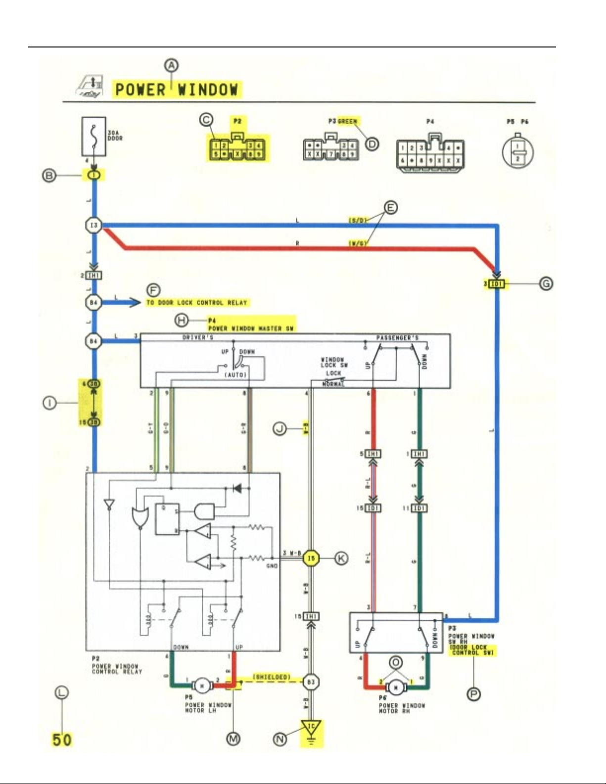
Q
WITH THE IGNITION SW TURNED ON, THE CURRENT FLOWS TO TERMINAL 3 OF THE POWER WINDOW MASTER SW, TERMINAL 2 OF THE POWER WINDOW CONTROL RELAY
AND TERMINAL 8 OF THE POWER WINDOW SW THROUGH THE DOOR FUSE.
1. DRIVER’S WINDOW “MANUAL UP” OPERATION BY MASTER SW
HOLDING MANUAL SW (DRIVER’S) ON “UP” POSITION LOCATED IN POWER WINDOW MASTER SW, THE CURRENT FLOWS TO TERMINAL 5 OF THE POWER WINDOW
CONTROL RELAY THROUGH TERMINAL 3 OF THE MASTER SW TERMINAL 2 TO OPERATE A POWER WINDOW CONTROL RELAY . THUS THE CURRENT INSIDE THE RELAY
FLOWS FROM TERMINAL 2 OF THE RELAY TERMINAL 1 TERMINAL 2 OF THE POWER WINDOW MOTOR TERMINAL 1 TERMINAL 4 OF THE RELAY TERMINAL
3 TO GROUND. THE MOTOR TURNS TO ASCENT THE WINDOW. RELEASING THIS SW, THE ROTATION OF MOTOR IS STOPPED AND THE WINDOWS CAN STOP AT WILL
POINT.
(FOR THE “MANUAL DOWN” OPERATION, CURRENT FLOWS IN THE REVERSE DIRECTION BECAUSE THE TERMINALS WHERE IT FLOWS ARE CHANGED).
2. DRIVER’S WINDOW “AUTO DOWN” OPERATION BY MASTER SW
ONCE THE “AUTO DOWN” BUTTON OF THE MASTER SW IS PUSHED, THE CURRENT FLOWS TERMINAL 9 OF THE POWER WINDOW CONTROL RELA Y THROUGH TERMINAL
3 OF THE MASTER SW TERMINALS 8 AND 9 TO OPERATE THE RELAY. THUS THE CURRENT INSIDE THE POWER WINDOW CONTROL RELAY FLOWS FROM TERMINAL
2 OF THE RELAY TERMINAL 4 TERMINAL 1 OF THE POWER WINDOW MOTOR TERMINAL 2 TERMINAL 1 OF THE RELAY TERMINAL 3 TO GROUND.
THE MOTOR CONTINUES THE ROTATION ENABLING TO DESCENT THE WINDOW.
THE WINDOW DESCENDS TO THE END POSITION. THE CURRENT WILL BE CUT OFF TO RELEASE THE AUTO DOWN FUNCTION BASED ON THE INCREASING CURRENT
BETWEEN TERMINAL 2 OF THE RELAY AND TERMINAL 1 IN RELAY.
3. DRIVER’S WINDOW AUTO DOWN RELEASE OPERATION BY MASTER SW
HOLDING THE MANUAL SW (DRIVER’S) ON “UP” POSITION IN OPERATING AUTO DOWN. THE CURRENT FROM TERMINAL 3 OF THE MASTER SW PASSING TERMINAL 2
FLOWS TERMINAL 5 OF THE RELAY AND RELEASES THE AUTO DOWN FUNCTION IN THE POWER WINDOW CONTROL RELAY. RELEASING THE HAND FROM SW , WINDOW
STOPS AND CONTINUING ON TOUCHING SW, THE FUNCTION SWITCHES TO MANUAL UP OPERATION.
4. PASSENGER’S WINDOW UP OPERATION (MASTER SW) AND WINDOW LOCK SW OPERATION
HOLDING PASSENGER’S WINDOW SW (MASTER SW) ON “UP”, THE CURRENT FLOWS FROM TERMINAL 3 OF THE MASTER SW PASSING TERMINAL 6 TO TERMINAL 3 OF
THE POWER WINDOW SW (PASSENGER’S) TERMINAL 4 TERMINAL 2 OF THE MOTOR TERMINAL 1 TERMINAL 9 OF THE POWER WINDOW SW TERMINAL
7 TERMINAL 1 OF THE MASTER SW TERMINAL 4 TO GROUND. THE MOTOR RUNS TO ASCENT THE WINDOW. RELEASING THIS SW, THE ROTATION OF MOTOR IS
STOPPED AND WINDOW CAN STOP AT WILL PLACE.
SWITCHING THE WINDOW LOCK SW IN “LOCK” POSITION, THE CIRCUIT IS OPENED AND STOPPED THE MOTOR ROTATION.
(FOR THE DOWN OPERATION, CURRENT FLOWS IN THE REVERSE DIRECTION BECAUSE THE TERMINALS WHERE IT FLOWS ARE CHANGED).
SYSTEM OUTLINE
R
P2 POWER WINDOW CONTROL RELAY
3–GROUND: ALWAYS CONTINUITY
2–GROUND: APPROX. 12 VOLTS WITH IGNITION SW AT ON POSITION
5–GROUND: APPROX. 12 VOLTS WITH IGNITION SW AT ON POSITION AND MASTER SW AT UP POSITION
8–GROUND: APPROX. 12 VOLTS WITH IGNITION SW AT ON POSITION AND MASTER SW AT AUTO DOWN POSITION
9–GROUND: APPROX. 12 VOLTS WITH IGNITION SW AT ON POSITION AND MASTER SW AT DOWN OR AUTO DOWN POSITION
P 4 POWER WINDOW MASTER SW
4–GROUND: ALWAYS CONTINUITY
3–GROUND: APPROX. 12 VOLTS WITH IGNITION SW AT ON POSITION
WINDOW LOCK SW
OPEN WITH WINDOW LOCK SW AT LOCK POSITION
SERVICE HINTS
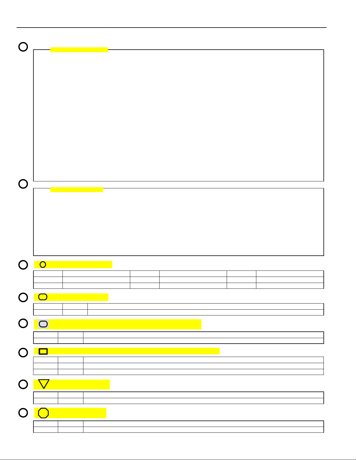
S
T
U
V
W
X
: PARTS LOCATION
CODE SEE PAGE CODE SEE PAGE CODE SEE PAGE
P2 21 P4 21 P6 21
P3 21 P5 21
: RELAY BLOCKS
CODE SEE PAGE RELAY BLOCK (RELAY BLOCK LOCATION)
1 16 R/B NO. 1 (INSTRUMENT PANEL LEFT SIDE)
: JUNCTION BLOCK AND WIRE HARNESS CONNECTOR
CODE SEE PAGE JUNCTION BLOCK AND WIRE HARNESS (CONNECTOR LOCATION)
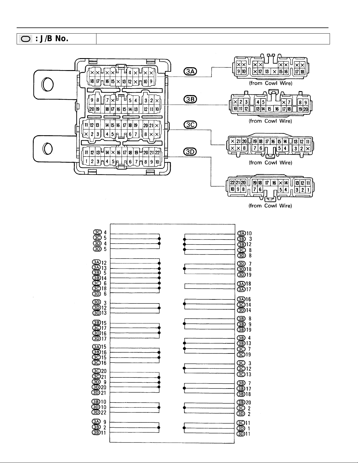
3B 14 J/B NO. 3 AND COWL WIRE (INSTRUMENT PANEL LEFT SIDE)
: CONNECTOR JOINING WIRE HARNESS AND WIRE HARNESS
CODE SEE PAGE JOINING WIRE HARNESS AND WIRE HARNESS (CONNECTOR LOCATION)
ID1 26 FRONT DOOR RH WIRE AND COWL WIRE (RIGHT KICK PANEL)
IH1 26 FRONT DOOR LH WIRE AND COWL WIRE (LEFT KICK PANEL)
: GROUND POINTS
CODE SEE PAGE GROUND POINT LOCATION
IC 24 COWL LEFT
: SPLICE POINTS
CODE SEE PAGE WIRE HARNESSES WITH SPLICE POINTS
I5 24 COWL WIRE
6
Q
: Explains the system outline.
R
: Indicates values or explains the function for reference during troubleshooting.
: Indicates the reference page showing the position on the vehicle of the parts in the system circuit.
S
Example: Part “P4” (Power Window Master SW) is on page 21 of the manual.
* The letter in the code is from the first letter of the part, and the number indicates its order
in parts starting with that letter.
Example: P
: Indicates the reference page showing the position on the vehicle of Relay Block Connectors in the
T
system circuit.
Example: Connector “1” is described on page 16 of this manual and is installed on the left side of the
instrument panel.
: Indicates the reference page showing the position on the vehicle of J/B and Wire Harness in the system
U
circuit.
Example: Connector “3B” connects the Cowl Wire and J/B No. 3. It is described on page 14 of this
manual, and is installed on the instrument panel left side.
V
: Indicates the reference page describing the wiring harness and wiring harness connector (the female
wiring harness is shown first, followed by the male wiring harness).
Example: Connector “ID1” connects the front door RH wire (female) and cowl wire (male). It is
described on page 26 of this manual, and is installed on the right side kick panel.
: Indicates the reference page showing the position of the ground points on the vehicle.
W
4
Part is 4th in order
Power Window Master SW
Example: Ground point “IC” is described on page 24 of this manual and is installed on the cowl left side.
: Indicates the reference page showing the position of the splice points on the vehicle.
X
Example: Splice point “I 5” is on the Cowl Wire Harness and is described on page 24 of this manual.
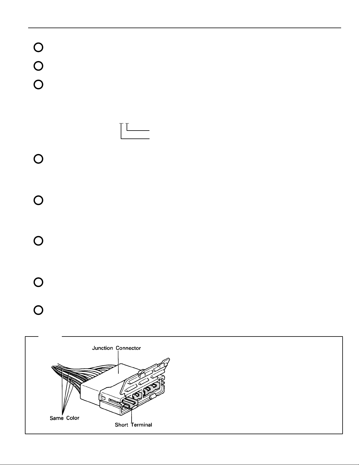
HINT:
Junction connector (code: J1, J2, J3, J4, J5,
J6, J7) in this manual include a short terminal
which is connected to a number of wire
harnesses. Always perform inspection with
the short terminal installed. (When installing
the wire harnesses, the harnesses can be
connected to any position within the short
terminal grouping.
Accordingly, in other vehicles, the same wire
harness from a different part.)
Wire harness sharing the same short terminal
grouping have the same color.
7
HOW TO USE THIS MANUAL
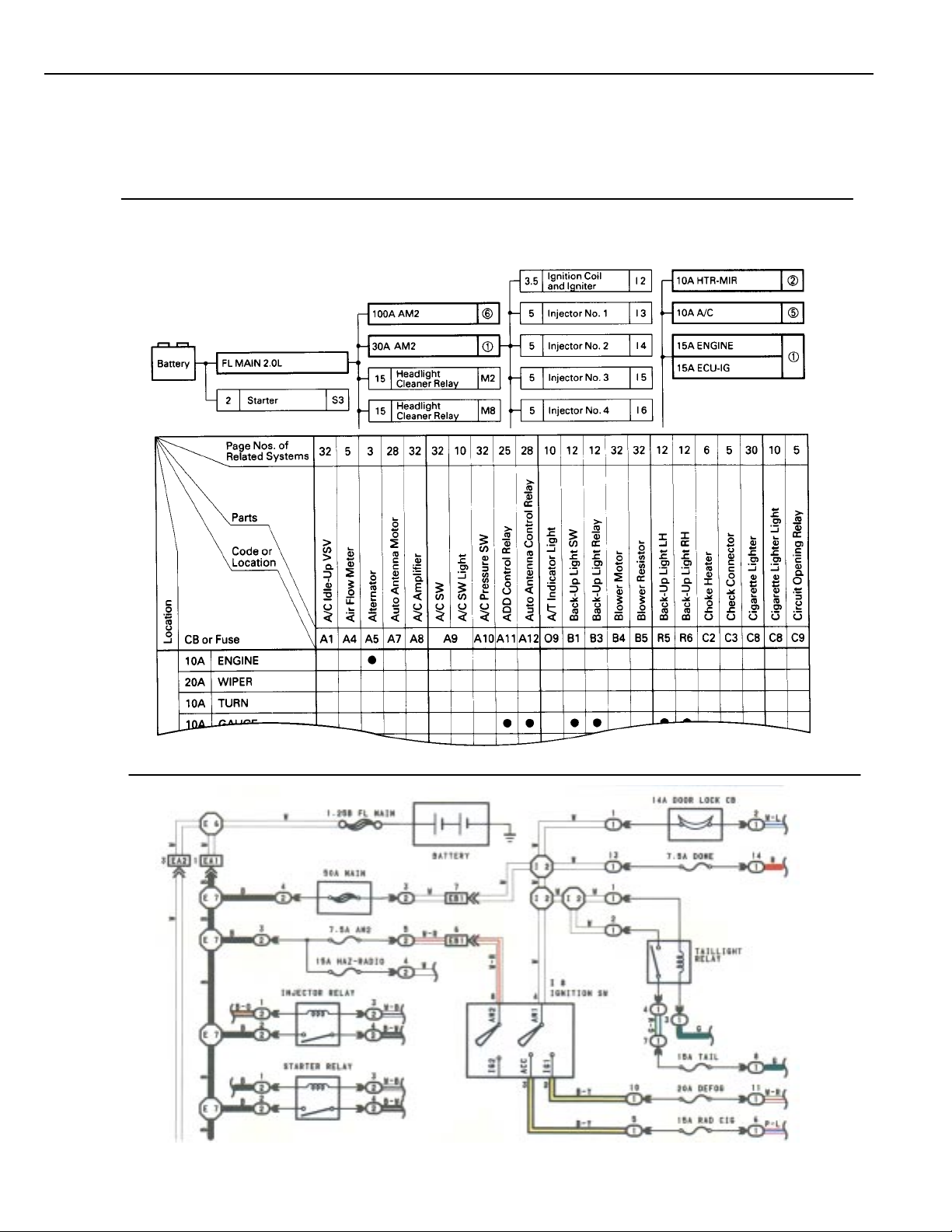
The “Current Flow Chart” section, describes which parts each power source (fuses, fusible links, and circuit breakers)
transmits current to. In the Power Source circuit diagram, the conditions when battery power is supplied to each system are
explained. Since all System Circuit diagrams start from the power source, the power source system must be fully understood.
POWER SOURCE (Current Flow Chart)
The chart below shows the route by which current flows from the battery to each electrical source (Fusible Link, Circuit
Breaker, Fuse, etc.) and other parts.
The next page and following pages show the parts to which each electrical source outputs current.
8
POWER SOURCE
* The system shown here is an EXAMPLE ONLY. It is different to the actual circuit shown in the SYSTEM CIRCUITS SECTION.
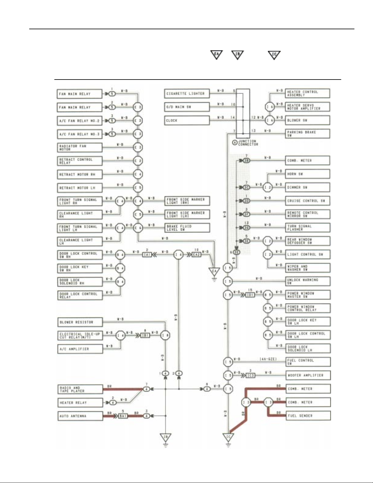
The ground points circuit diagram shows the connections from all major parts to the respective ground points. When
troubleshooting a faulty ground point, checking the system circuits which use a common ground may help you identify the
problem ground quickly. The relationship between ground points ( , , and shown below) can also be
checked this way.
GROUND POINT
* The system shown here is an EXAMPLE ONLY. It is different to the actual circuit shown in the SYSTEM CIRCUITS SECTION.
9
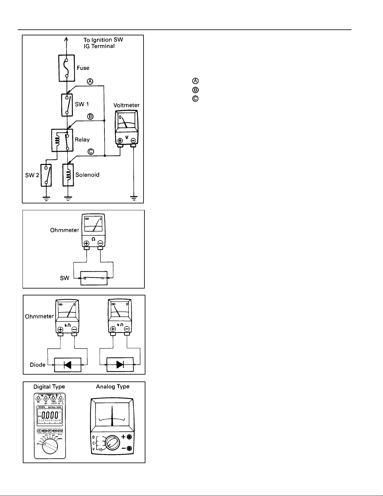
TROUBLESHOOTING
VOLTAGE CHECK
(a) Establish conditions in which voltage is present at the
check point.
Example:
– Ignition SW on
– Ignition SW and SW 1 on
– Ignition SW, SW 1 and Relay on (SW 2 off)
(b) Using a voltmeter, connect the negative lead to a good
ground point or negative battery terminal, and the
positive lead to the connector or component terminal.
This check can be done with a test light instead of a
voltmeter.
CONTINUITY AND RESISTANCE CHECK
(a) Disconnect the battery terminal or wire so there is no
voltage between the check points.
(b) Contact the two leads of an ohmmeter to each of the
check points.
If the circuit has diodes, reverse the two leads and check
again.
When contacting the negative lead to the diode positive side
and the positive lead to the negative side, there should be
continuity.
When contacting the two leads in reverse, there should be no
continuity.
(c) Use a volt/ohmmeter with high impedance (10 kΩ/V
minimum) for troubleshooting of the electrical circuit.
10
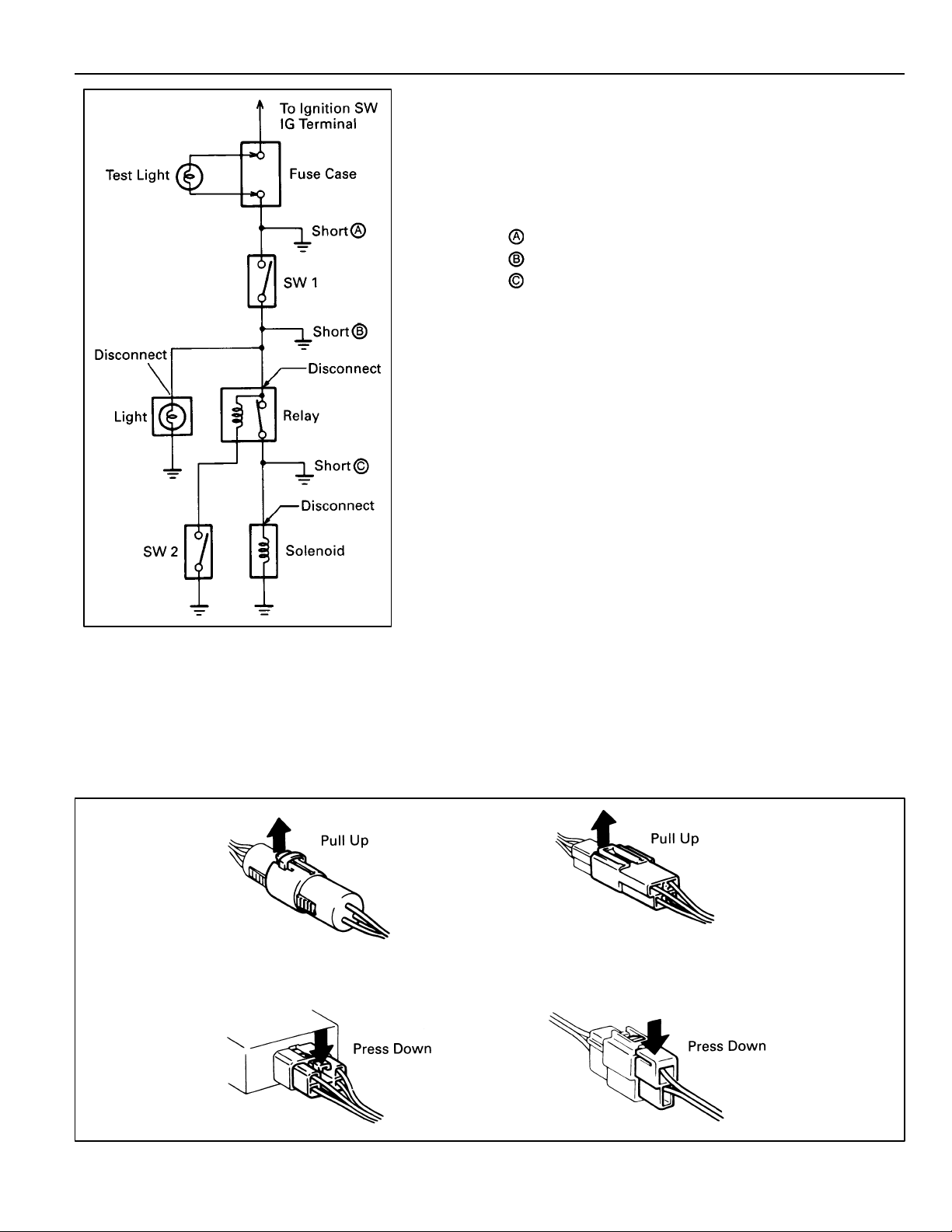
FINDING A SHORT CIRCUIT
(a) Remove the blown fuse and disconnect all loads of the
fuse.
(b) Connect a test light in place of the fuse.
(c) Establish conditions in which the test light comes on.
Example:
– Ignition SW on
– Ignition SW and SW 1 on
– Ignition SW, SW 1 and Relay on (Connect the
Relay) and SW 2 off (or Disconnect SW 2)
(d) Disconnect and reconnect the connectors while
watching the test light.
The short lies between the connector where the test
light stays lit and the connector where the light goes
out.
(e) Find the exact location of the short by lightly shaking
the problem wire along the body.
CAUTION
(a) Do not open the cover or the case of the ECU unless
absolutely necessary . (If the IC terminals are touched,
the IC may be destroyed by static electricity.)
(b) When replacing the internet mechanism (ECU part) of
the digital meter , be careful that no part of your body or
clothing comes in contact with the terminals of leads
from the IC, etc. of the replacement part (spare part).
DISCONNECTION OF MALE AND FEMALE
CONNECTORS
To pull apart the connectors, pull on the connector itself, not the
wire harness.
HINT: Check to see what kind of connector you are disconnecting
before pulling apart.
11
TROUBLESHOOTING
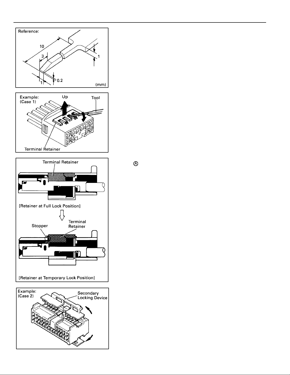
HOW TO REPLACE TERMINAL
(with terminal retainer or secondary locking
device)
1. PREPARE THE SPECIAL TOOL
HINT: To remove the terminal from the connector, please
construct and use the special tool or like object shown
on the left.
2. DISCONNECT CONNECTOR
3. DISENGAGE THE SECONDARY LOCKING DEVICE OR
TERMINAL RETAINER.
(a) Locking device must be disengaged before the
terminal locking clip can be released and the terminal
removed from the connector.
(b) Use a special tool or the terminal pick to unlock the
secondary locking device or terminal retainer.
NOTICE:
Do not remove the terminal retainer from connector body.
For Non–Waterproof Type Connector
HINT: The needle insertion position varies according
to the connector ’s shape (number of terminals
etc.), so check the position before inserting it.
“Case 1”
Raise the terminal retainer up to the temporary
lock position.
“Case 2”
Open the secondary locking device.
12
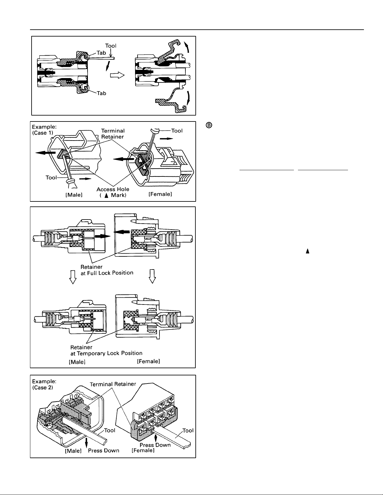
For Waterproof Type Connector
HINT: Terminal retainer color is different
according to connector body.
Example:
Terminal Retainer
Black or White : Gray
Black or White : Dark Gray
Gray or White : Black
“Case 1”
Type where terminal retainer is pulled up
to the temporary lock position (Pull Type).
Insert the special tool into the terminal
retainer access hole ( Mark) and pull the
terminal retainer up to the temporary lock
position.
HINT: The needle insertion position varies
according to the connector’s shape
(Number of terminals, etc.), so check the
position before inserting it.
: Connector Body
“Case 2”
Type which cannot be pulled as far as
Power Lock insert the tool straight into the
access hole of terminal retainer as shown.
13
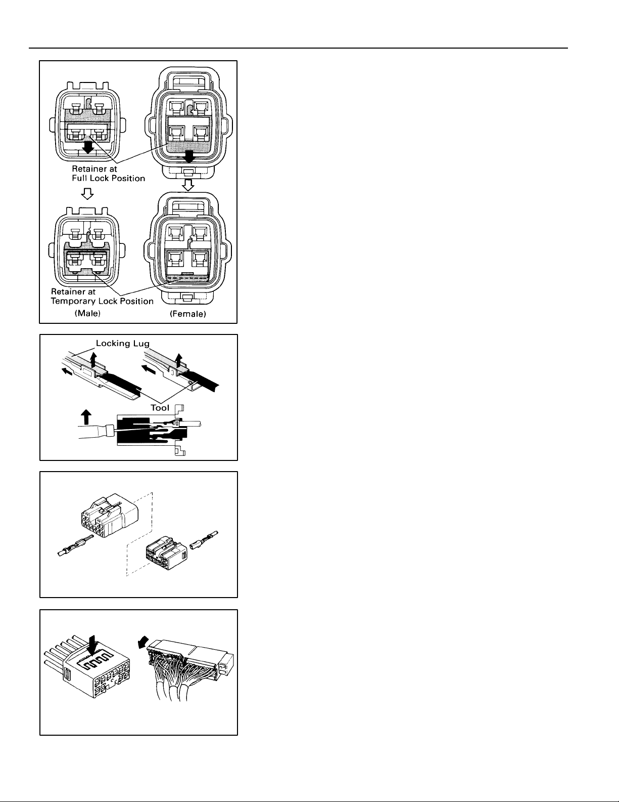
TROUBLESHOOTING
Push the terminal retainer down to the temporary lock
position.
(c) Release the locking lug from terminal and pull the
terminal out from rear.
4. INSTALL TERMINAL TO CONNECTOR
(a) Insert the terminal.
HINT:
1. Make sure the terminal is positioned correctly.
2. Insert the terminal until the locking lug locks firmly.
3. Insert the terminal with terminal retainer in the
temporary lock position.
(b) Push the secondary locking device or terminal retainer
in to the full lock position.
14
5. CONNECT CONNECTOR

ABBREVIATIONS
The following abbreviations are used in this manual.
ABS = Anti–Lock Brake System
ACIS = Acoustic Control Induction System
A/C = Air Conditioning
A/T = Automatic Transmission
COMB. = Combination
C/P = Coupe
ECU = Electronic Control Unit
EFI = Electronic Fuel Injection
EGR = Exhaust Gas Recirculation
ESA = Electronic Spark Advance
Ex. = Except
FL = Fusible Link
IAC = Idle Air Control
ISC = Idle Speed Control
J/B = Junction Block
LH = Left-Hand
MFI = Multiport Fuel Injection
M/T = Manual Transmission
O/D = Overdrive
R/B = Relay Block
RH = Right–Hand
RPM = Engine Speed
S/D = Sedan
SFI = Sequential Multiport Fuel Injection
SRS = Supplemental Restraint System
SW = Switch
TEMP. = Temperature
VSV = Vacuum Switching Valve
W/G = Wagon
w/ = With
w/o = Without
ABBREVIATIONS
* The titles given inside the components are the names of the terminals (terminal codes) and
are not treated as being abbreviations.
15
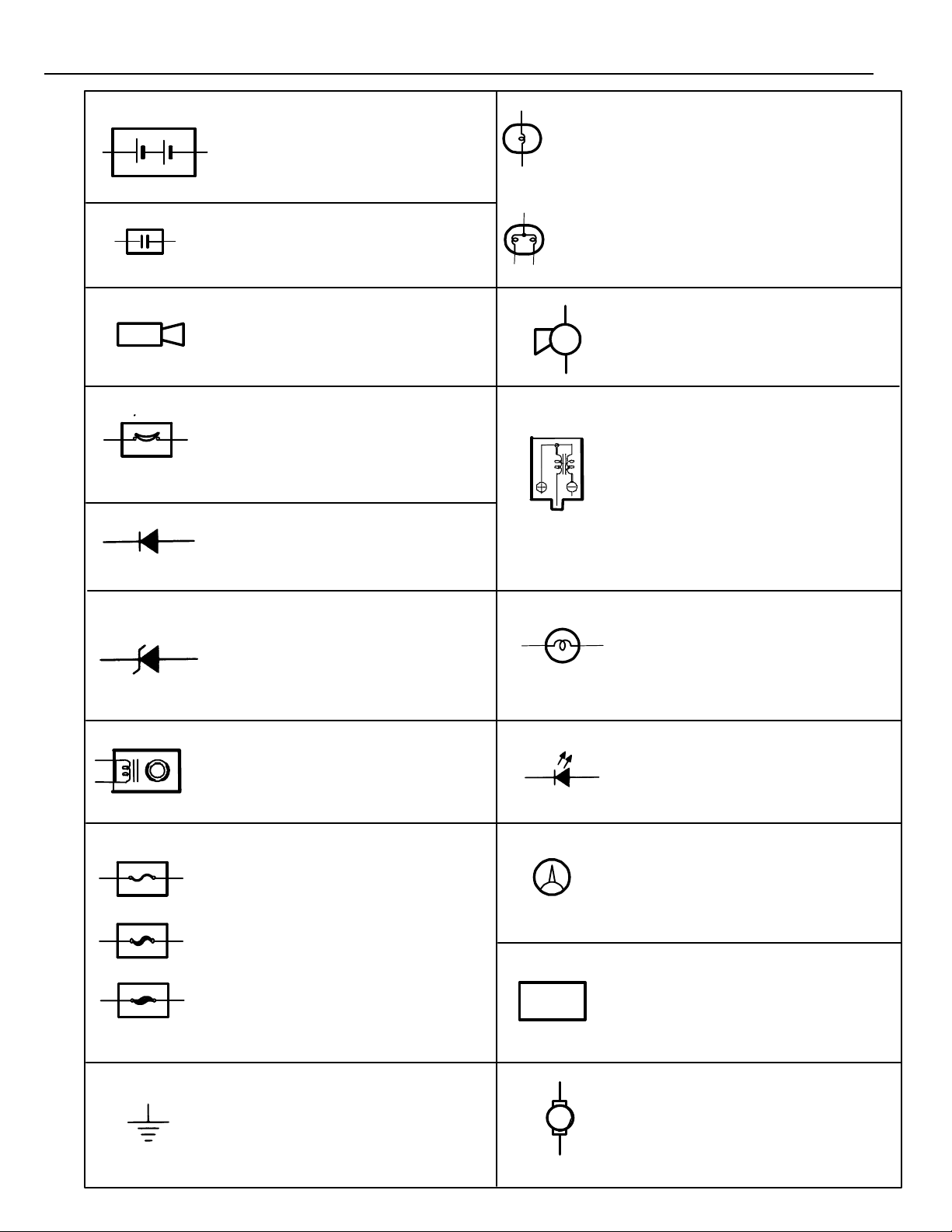
GLOSSARY OF TERMS AND SYMBOLS
BATTERY
Stores chemical energy and
converts it into electrical energy.
Provides DC current for the auto’s
various electrical circuits.
CAPACITOR (Condenser)
A small holding unit for temporary
storage of electrical voltage.
CIGARETTE LIGHTER
An electric resistance heating
element.
CIRCUIT BREAKER
Basically a reusable fuse, a circuit
breaker will heat and open if too
much current flows through it. Some
units automatically reset when cool,
others must be manually reset.
DIODE
A semiconductor which allows
current flow in only one direction.
HEADLIGHTS
1. SINGLE
FILAMENT
2. DOUBLE
FILAMENT
Current flow causes a headlight
filament to heat up and emit light.
A headlight may have either a
single (1) filament or a double (2)
filament.
HORN
An electric device which sounds a
loud audible signal.
IGNITION COIL
Converts low–voltage DC current
into high–voltage ignition current
for firing the spark plugs.
(for Medium Current Fuse)
(for High Current Fuse or
Fusible Link.)
16
DIODE, ZENER
A diode which allows current flow
in one direction but blocks reverse
flow only up to a specific voltage.
Above that potential, it passes the
excess voltage. This acts as a
simple voltage regulator.
DISTRIBUTOR, IIA
Channels high–voltage current
from the ignition coil to the
individual spark plugs.
FUSE
A thin metal strip which burns
through when too much current
flows through it, thereby stopping
current flow and protecting a
circuit from damage.
FUSIBLE LINK
A heavy–gauge wire placed in
high amperage circuits which
burns through on overloads,
thereby protecting the circuit.
The numbers indicate the cross–
section surface area of the wires.
GROUND
The point at which wiring attaches
to the Body, thereby providing a
return path for an electrical circuit;
without a ground, current cannot
flow.
FUEL
M
LIGHT
Current flow through a filament
causes the filament to heat up
and emit light.
LED (LIGHT EMITTING DIODE)
Upon current flow, these diodes
emit light without producing the
heat of a comparable light.
METER, ANALOG
Current flow activates a magnetic
coil which causes a needle to
move, thereby providing a relative
display against a background
calibration.
METER, DIGITAL
Current flow activates one or
many LED’s, LCD’s, or fluorescent
displays, which provide a relative
or digital display.
MOTOR
A power unit which converts
electrical energy into mechanical
energy, especially rotary motion.
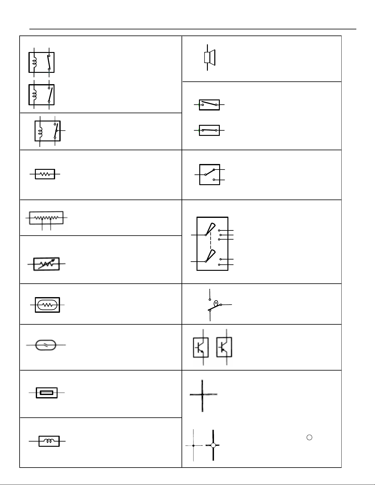
RELAY
1. NORMALLY
CLOSED
2. NORMALLY
OPEN
RELAY, DOUBLE THROW
A relay which passes current
through one set of contacts or the
other.
Basically, an electrically
operated switch which may
be normally closed (1) or
open (2).
Current flow through a
small coil creates a
magnetic field which either
opens or closes an
attached switch.
SPEAKER
An electromechanical device
which creates sound waves from
current flow.
SWITCH, MANUAL
1. NORMALLY
OPEN
2. NORMALLY
CLOSED
Opens and
closes circuits,
thereby
stopping (1) or
allowing (2)
current flow.
RESISTOR
An electrical component with a
fixed resistance, placed in a circuit
to reduce voltage to a specific
value.
RESISTOR, TAPPED
A resistor which supplies two or
more different non adjustable
resistance values.
RESISTOR, VARIABLE or
RHEOSTAT
A controllable resistor with a
variable rate of resistance.
Also called a potentiometer or
rheostat.
SENSOR (Thermistor)
A resistor which varies its
resistance with temperature.
SENSOR, ANALOG SPEED
Uses magnetic impulses to open
and close a switch to create a
signal for activation of other
components.
SWITCH, DOUBLE THROW
A switch which continuously
passes current through one set
of contacts or the other.
SWITCH,
IGNITION
A key operated switch with
several positions which allows
various circuits, particularly the
primary ignition circuit, to
become operational.
SWITCH, WIPER PARK
Automatically returns wipers to
the stop position when the wiper
switch is turned off.
TRANSISTOR
A solidstate device typically used
as an electronic relay; stops or
passes current depending on the
voltage applied at “base.”
SHORT PIN
Used to provide an unbroken
connection within a junction block.
SOLENOID
An electromagnetic coil which
forms a magnetic field when
current flows, to move a plunger,
etc.
WIRES
(1) NOT
CONNECTED
(2) SPLICED
Wires are always
drawn as straight lines
on wiring diagrams.
Crossed wires (1)
without a black dot at
the junction are not
joined; crossed wires
(2) with a black dot or
octagonal ( ) mark at
the junction are spliced
(joined) connections.
17
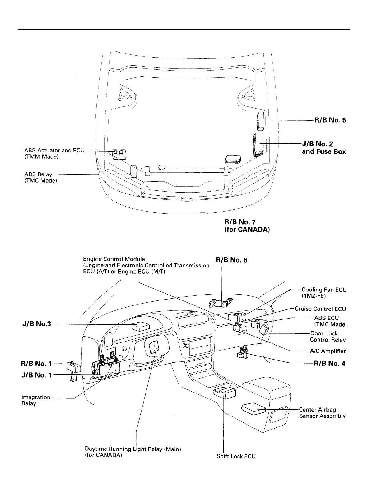
RELAY LOCATIONS
[Engine Compartment]
[Instrument Panel]
18
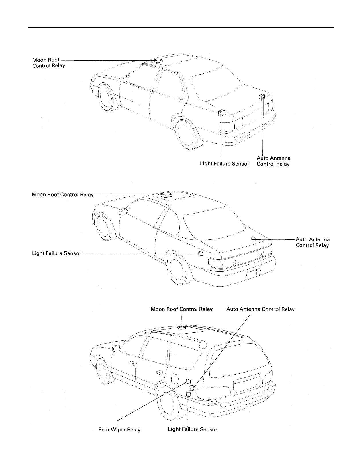
[Body]
[Sedan]
[Coupe]
[Wagon]
19
RELAY LOCATIONS
,
,,,
,,
: J/B No. 1 Instrument Panel Left
(See Page 18)
20
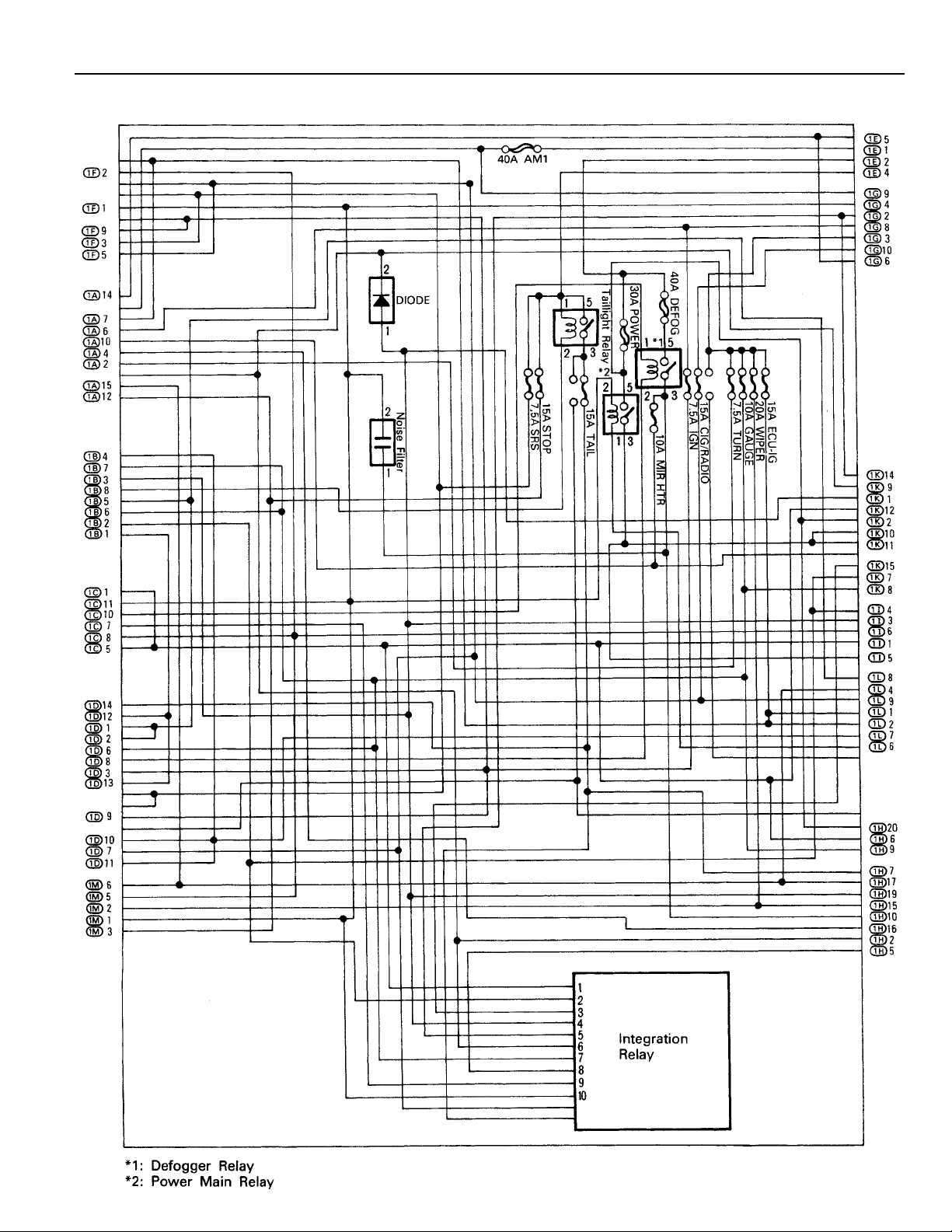
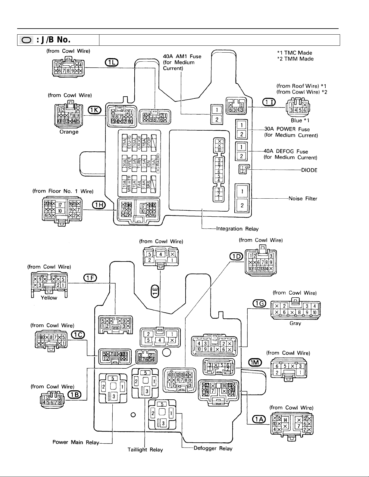
[J/B No. 1 Inner Circuit]
21
RELAY LOCATIONS
,
,,,
,,
: J/B No. 2 Engine Compartment Left
(See Page 18)
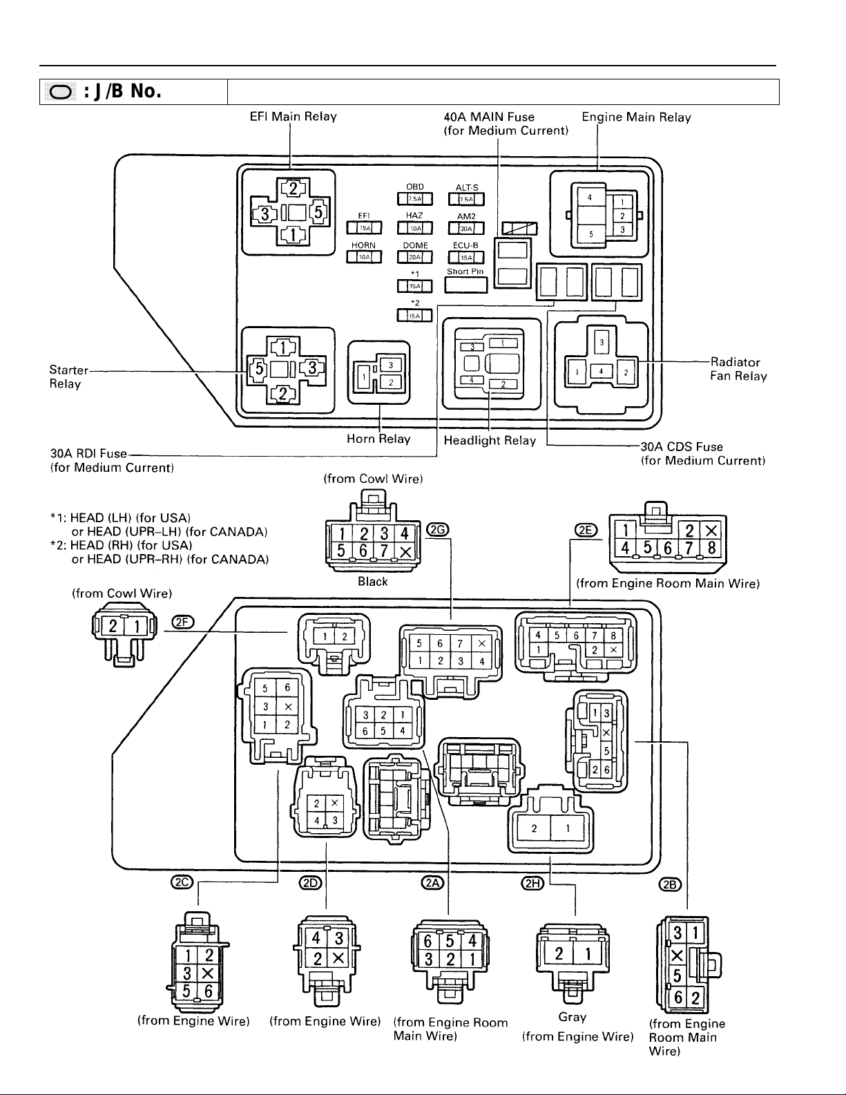
22
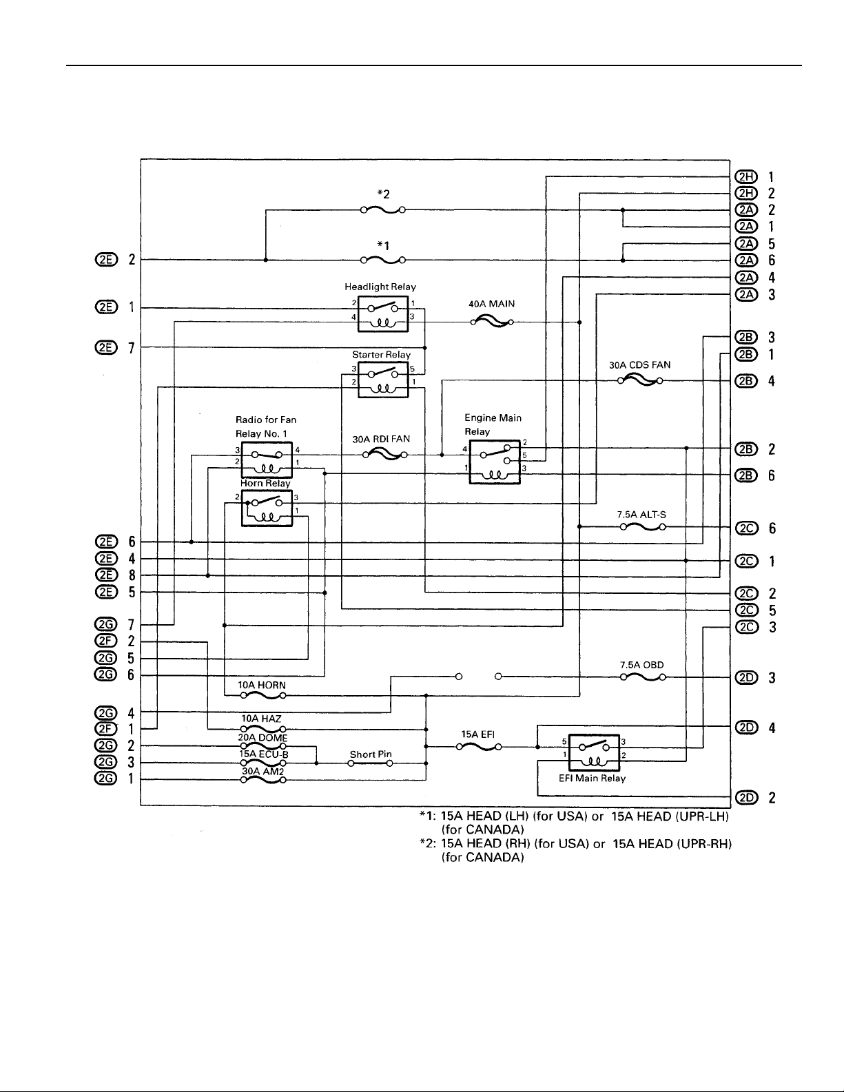
[J/B No. 2 Inner Circuit]
23
RELAY LOCATIONS
,
,,,
,,
: J/B No. 3 Behind Combination Meter
(See Page 18)
[J/B No. 3 Inner Circuit]
24
1
: R/B No. 1 Left Kick Panel
(See Page 18)
4
: R/B No. 4 Right Kick Panel
(See Page 18)
25
RELAY LOCATIONS
5
: R/B No. 5 Engine Compartment Left
(for 1MZ–FE)
(See Page 18)
6
: J/B No. 6 Behind Glove Box
(for 5S–FE)
(See Page 18)
26
7
: R/B No. 7 Near The Battery
(See Page 18)
27
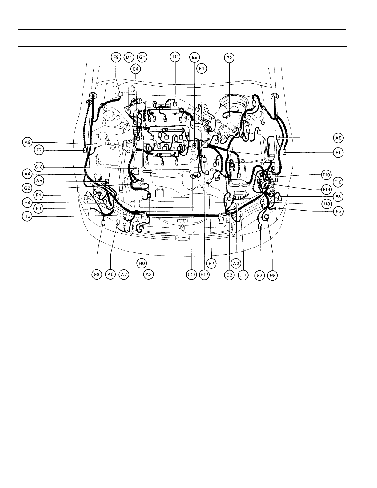
ELECTRICAL WIRING ROUTING
Position of Parts in Engine Compartment
[1MZ–FE]
A 2 A/C Triple Pressure SW (A/C Dual and Single Pressure F 1 Front Airbag Sensor LH
A 3 A/C Magnetic Clutch and Lock Sensor F 3 Front Clearance Light LH
A 4 ABS Actuator F 4 Front Clearance Light RH
A 5 ABS Actuator F 5 Front Side Marker LH
A 6 ABS Relay F 6 Front Side Marker RH
A 7 ABS Relay F 7 Front Turn Signal Light LH
A 8 ABS Speed Sensor Front LH F 8 Front Turn Signal Light RH
A 9 ABS Speed Sensor Front RH F 9 Front Wiper Motor
B 2 Brake Fluid Level SW F 16 Fuse Box
C 2 Cruise Control Actuator
C 17 Camshaft Position Sensor G 1 Generator (Alternator)
C 18 Crankshaft Position Sensor G 2 Generator (Alternator)
D 1 Data Link Connector 1 (Check Connector) H 1 Headlight Hi LH
D 2 Distributor H 2 Headlight Hi RH
E 1 EGR Gas Temp. Sensor H 4 Headlight Lo RH
E 2 Electronic Controlled Transmission Solenoid H 5 Horn LH
E 4 Engine Coolant Temp. Sensor (EFI Water Temp. H 6 Horn RH
E 5 Engine Coolant Temp. Sensor (Water Temp. Sensor) H 12 Heated Oxygen Sensor (Bank 2 Sensor 1)
SW) F 2 Front Airbag Sensor RH
F 10 Fuse Box
F 18 Fuse Box
H 3 Headlight Lo LH
Sensor) H 11 Heated Oxygen Sensor (Bank 1 Sensor 1)
(for Cooling Fan)
28
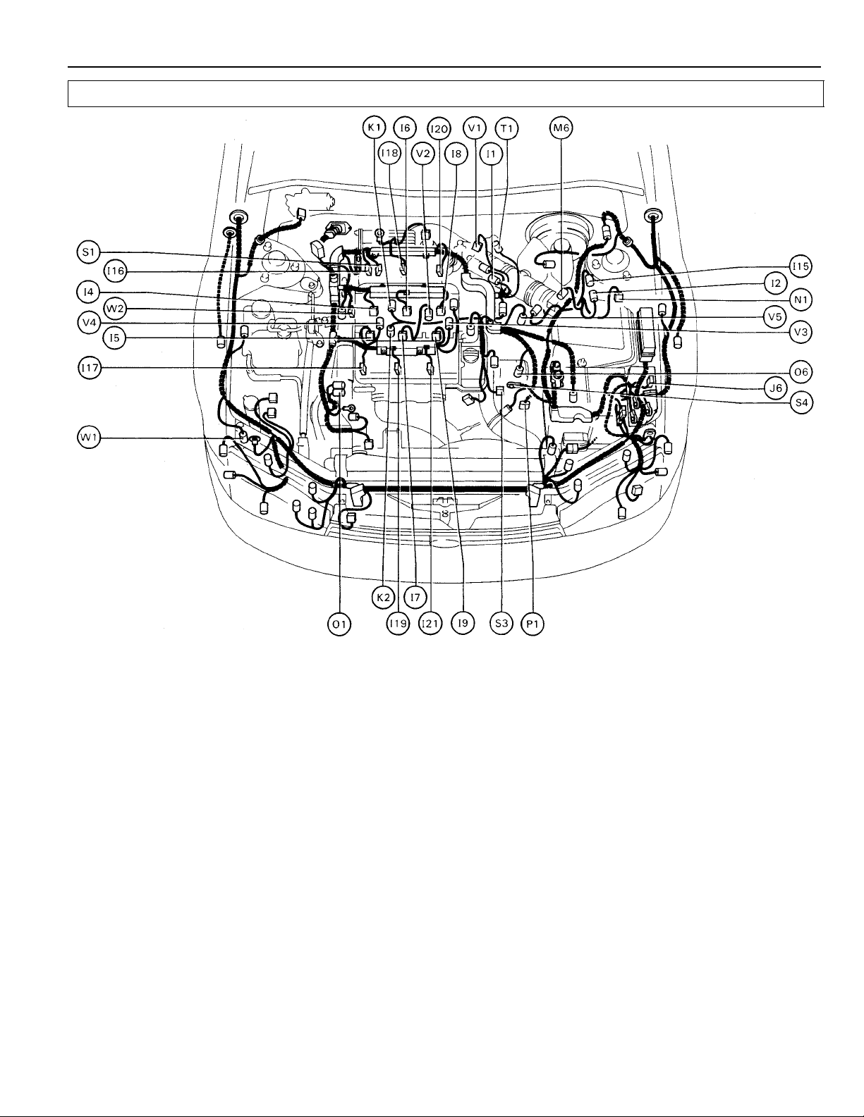
[1MZ–FE]
Position of Parts in Engine Compartment
I 1 Idle Air Control Valve (ISC Valve) N 1 Noise Filter (for Ignition System)
I 2 Igniter
I 4 Injector No. 1 O 1 Oil Pressure SW
I 5 Injector No. 2 O 6 O/D Direct Clutch Speed Sensor
I 6 Injector No. 3
I 7 Injector No. 4 P 1 Park/Neutral Position SW (Neutral Start SW) (A/T)
I 8 Injector No. 5
I 9 Injector No. 6 S 1 Solenoid Valve (for Hydrauric Motor)
I 15 Igniter S 3 Starter
I 16 Ignition Coil No. 1 S 4 Starter
I 17 Ignition Coil No. 2
I 18 Ignition Coil No. 3 T 1 Throttle Position Sensor
I 19 Ignition Coil No. 4
I 20 Ignition Coil No. 5 V 1 VSV (for A/C Idle–Up)
I 21 Ignition Coil No. 6 V 2 VSV (for EGR System)
J 6 Junction Connector V 4 VSV (for Intake Air Control)
K 1 Knock Sensor 1
K 2 Knock Sensor 2 W 1 Washer Motor
M 6 Mass Air Flow (Air Flow Meter)
V 3 VSV (for Fuel Pressure Up)
V 5 V ehicle Speed Sensor (Speed Sensor)
W 2 Water Temp. Sender
29
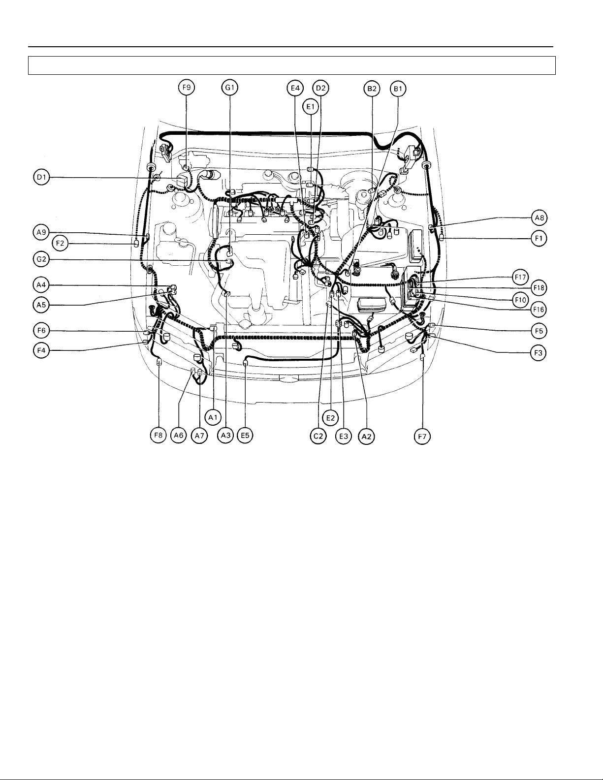
ELECTRICAL WIRING ROUTING
Position of Parts in Engine Compartment
[5S–FE]
A 1 A/C Condenser Fan Motor E 1 EGR Gas Temp. Sensor
A 2 A/C Triple Pressure SW (A/C Dual and Single Pressure E 2 Electronic Controlled Transmission Solenoid
A 3 A/C Magnetic Clutch and Lock Sensor E 4 Engine Coolant Temp. Sensor (EFI Water T emp.
A 4 ABS Actuator Sensor)
A 5 ABS Actuator E 5 Water Temp. SW (for Cooling Fan)
A 6 ABS Relay
A 7 ABS Relay F 1 Front Airbag Sensor LH
A 8 ABS Speed Sensor Front LH F 2 Front Airbag Sensor RH
A 9 ABS Speed Sensor Front RH F 3 Front Clearance Light LH
B 1 Back–Up Light SW (M/T) F 5 Front Side Marker LH
B 2 Brake Fluid Level SW F 6 Front Side Marker RH
C 2 Cruise Control Actuator F 8 Front Turn Signal Light RH
D 1 Data Link Connector 1 (Check Connector) F 10 Fuse Box
D 2 Distributor F 16 Fuse B o x
SW) E 3 Electronic Controlled Transmission Solenoid
F 4 Front Clearance Light RH
F 7 Front Turn Signal Light LH
F 9 Front Wiper Motor
F 17 Fuse Box
F 18 Fuse Box
G 1 Generator (Alternator)
G 2 Generator (Alternator)
30
 Loading...