

BODY PANEL REPLACEMENT
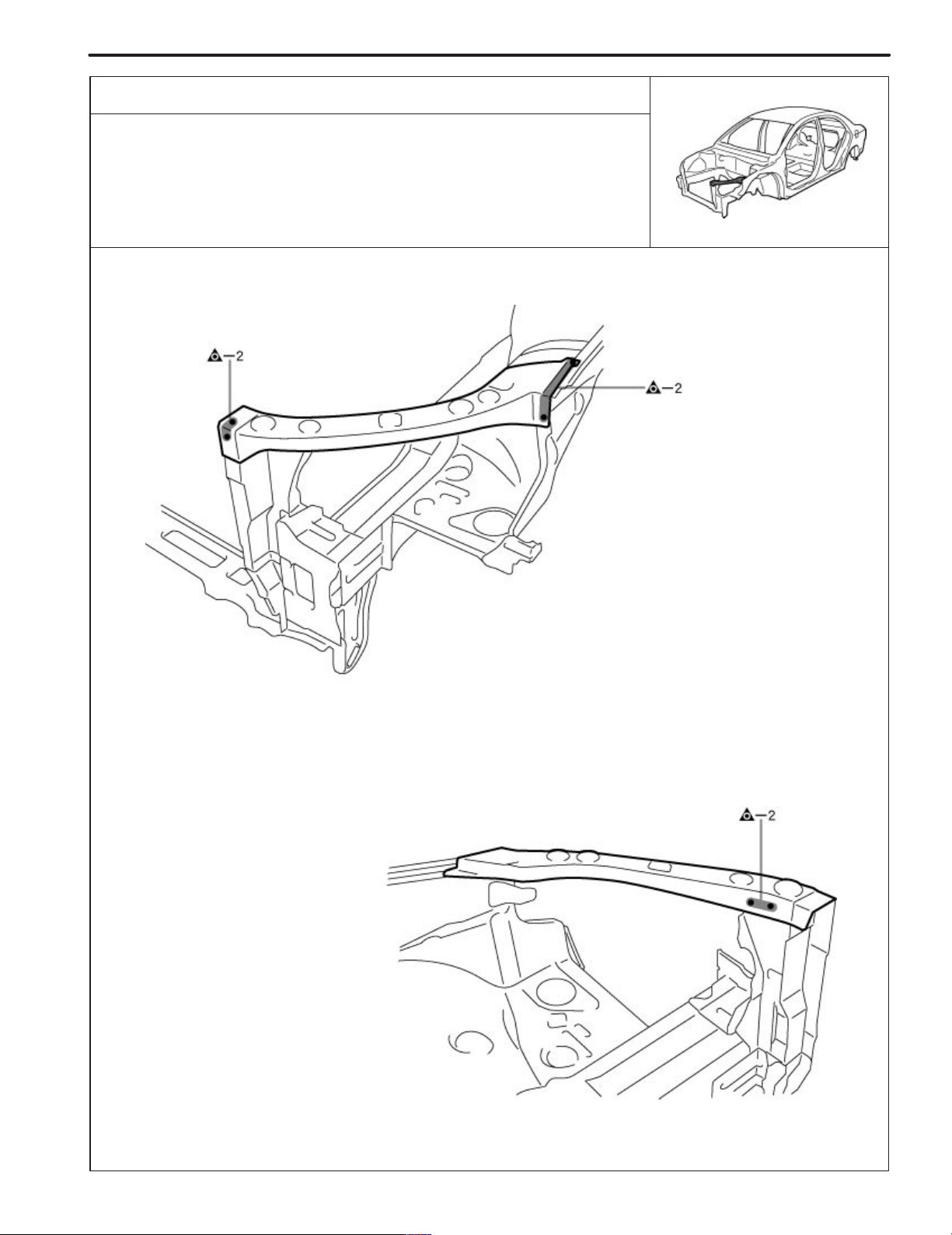
RADIATOR UPPER SUPPORT (ASSY)
REMOVAL
BP-1
F14459-A
F14459
BP-2
BODY PANEL REPLACEMENT
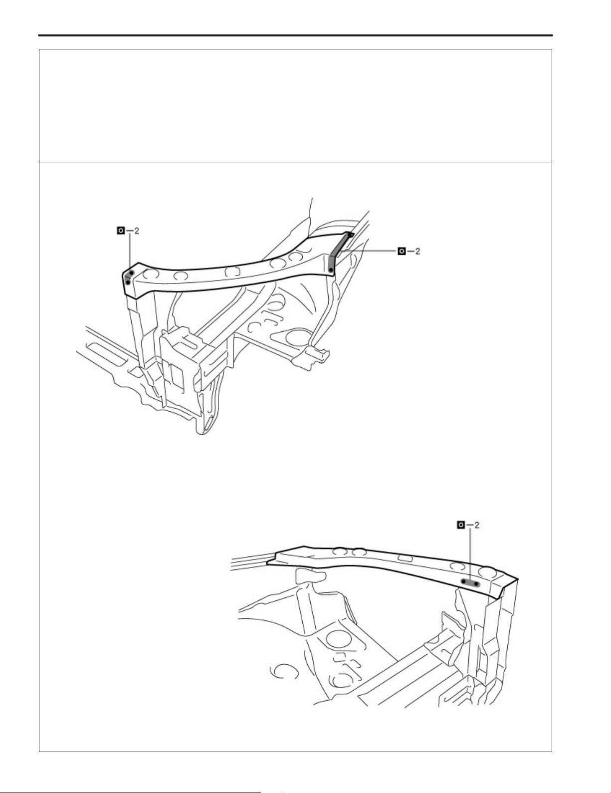
INSTALLATION
! Temporarily install the new parts and measure each part of the new parts in accordance with the body dimension
diagram. (See the body dimension diagram)
! Inspect the fitting of the related parts around the new parts before welding. This affects the appearance of the
finish.
! After welding, apply the polyurethane foam to the corresponding parts.
! After welding, apply body sealer and under-coating to the corresponding parts.
! After applying the top coat layer, apply anti-rust agent to the inside of the necked section structural weld spots.
F14460
PAINT ! COATING
PC-19
BODY PANEL ANTI-CHIPPING PAINT APPLICATION AREAS
HINT:
1) Anti-chipping paint should be applide to some areas before the second coat and to others after the top coat.
2) If other areas are accidentally coated, wipe of the paint immediately with a rag soaked in grease, wax and
silicone remover.
PVC Chipping Primer
Urethane Primer
Soft - Chip Primer (Poly Olefine)
F14419
PC-18
PAINT ! COATING
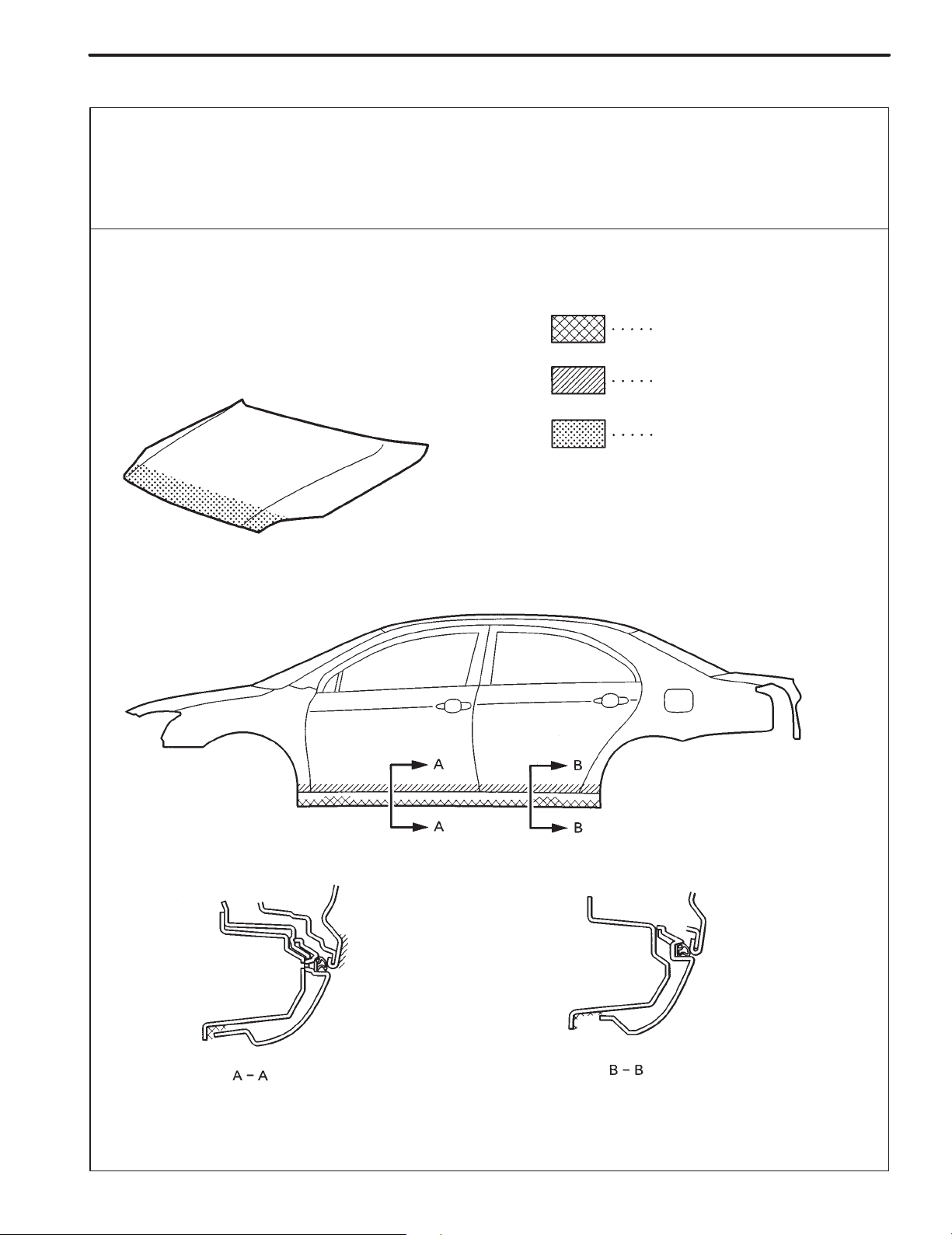
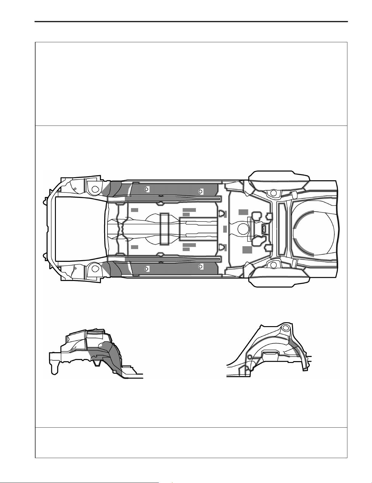
SILENCER SHEET INSTALLATION AREAS
Thickness of Asphalt Sheet
1.6mm (0.063in.)
1.8mm (0.071in.)
3.0mm (0.118in.)
F14418
PAINT ! COATING
PC-15
BODY PANEL ANTI-RUST AGENT (WAX) APPLICATION AREAS
HINT:
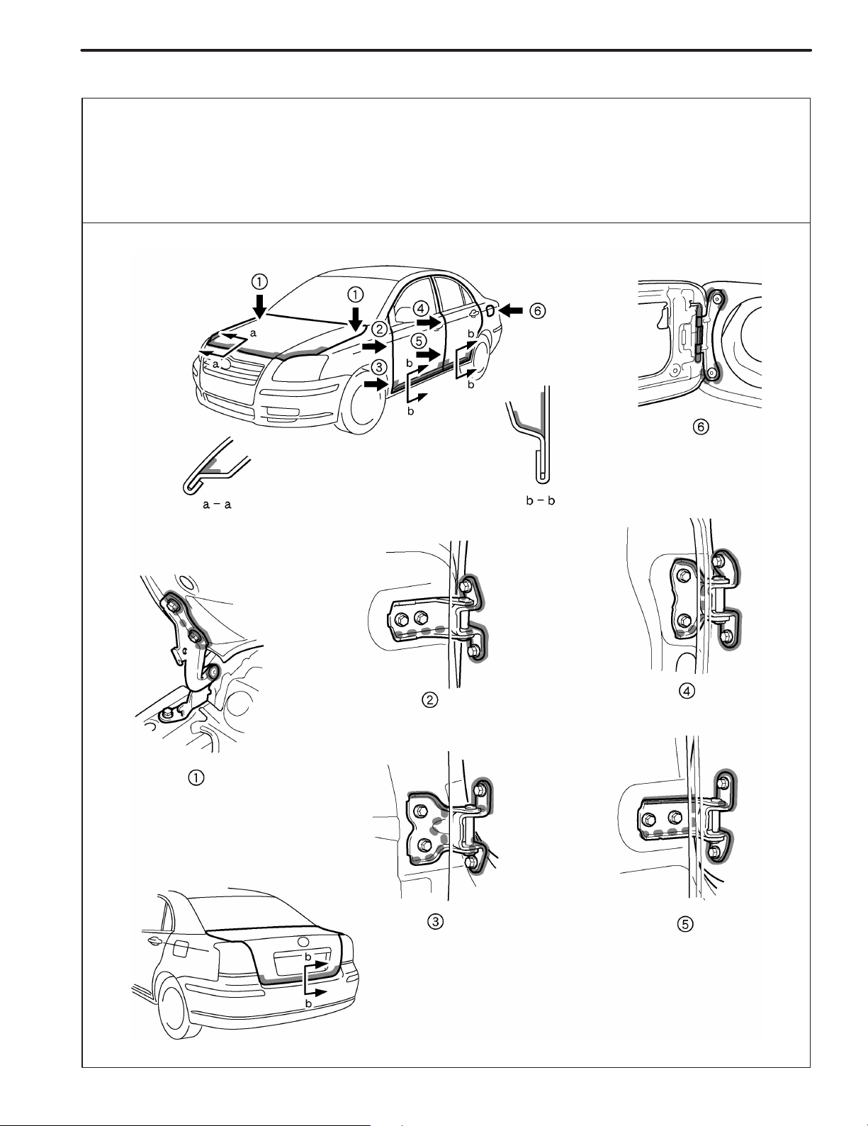
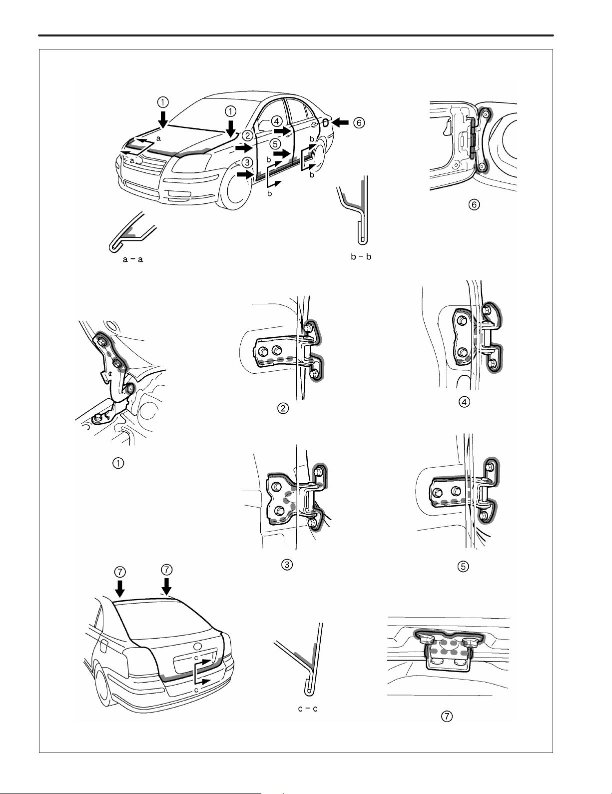
1) Whenever adjusting the doors and hoods, apply anti-rust agent (wax) around the hinges.
2) Even if partially repairing a part, apply anti-rust agent (wax) over the entire application area of the part.
3) Wipe off the anti-rust agent immediately with a rag soaked in a grease, wax and silicone remover, if accidently
applied to other areas.
[Sedan]
F14412
PC-16
[Liftback]
PAINT ! COATING
F14414
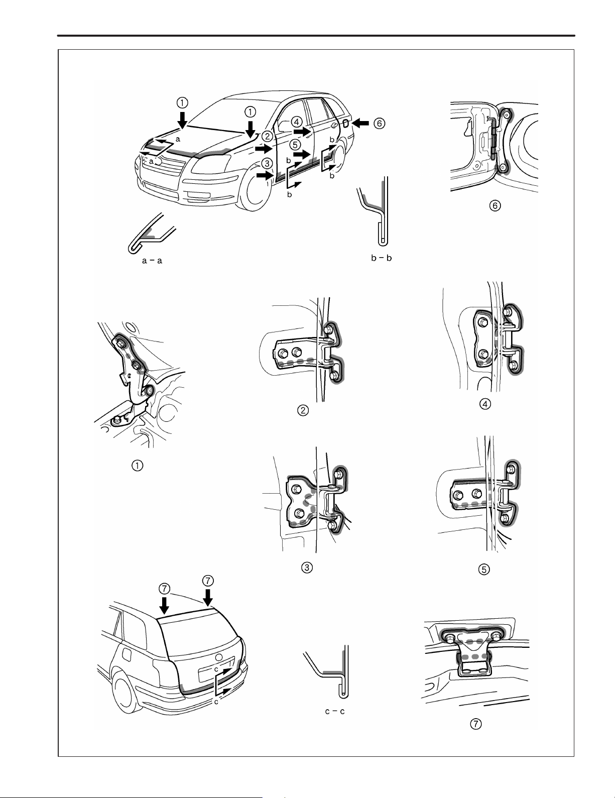
[Wagon]
PAINT ! COATING
PC-17
F14413
PC-12
PAINT ! COATING
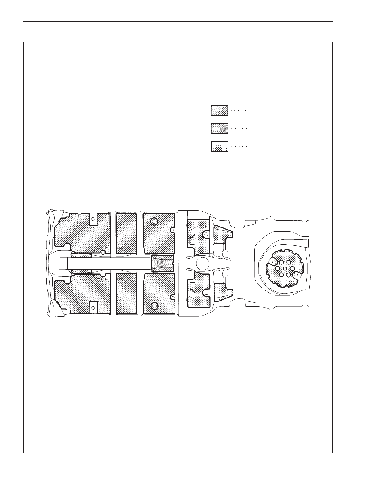
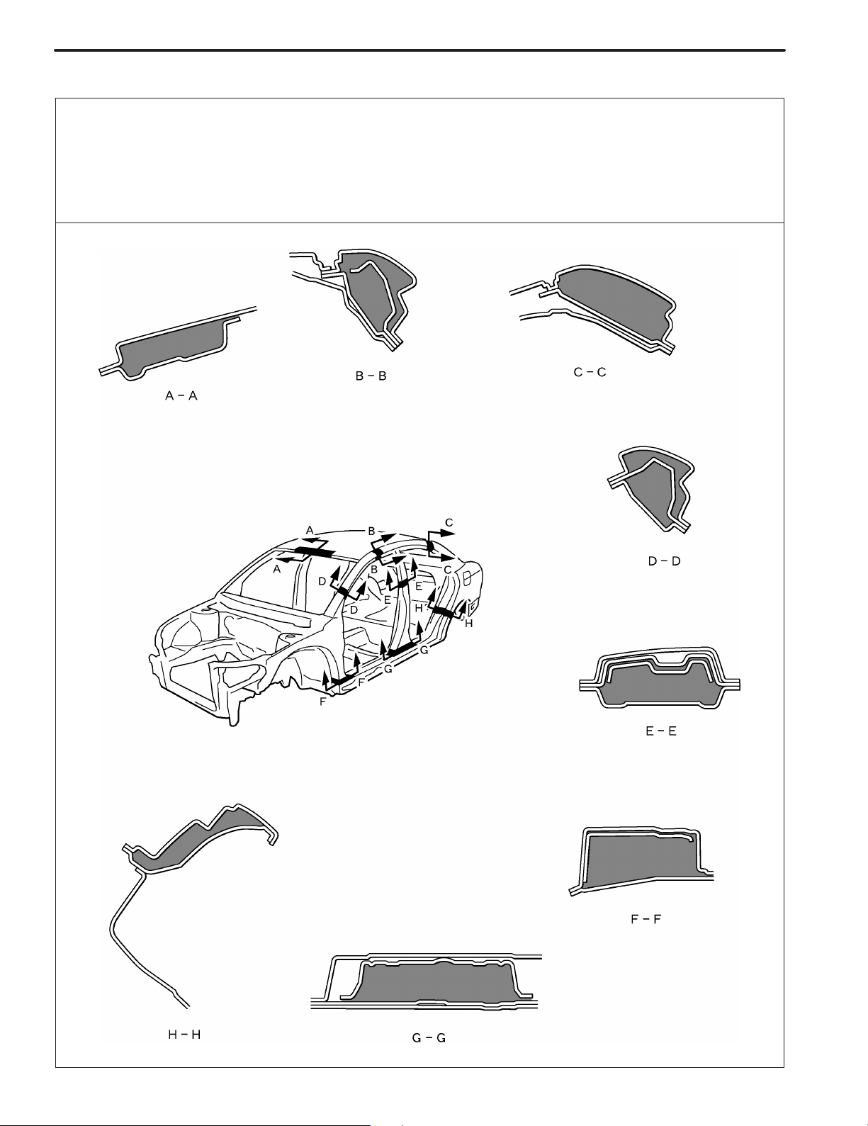
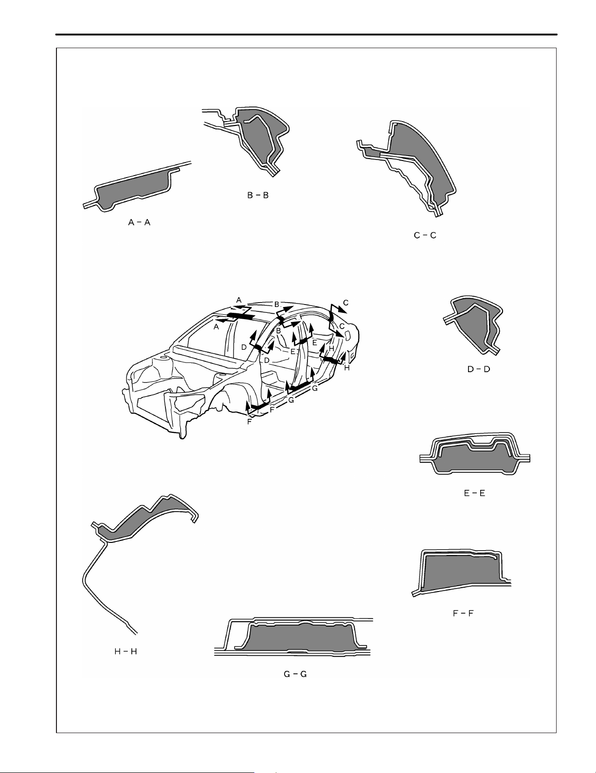
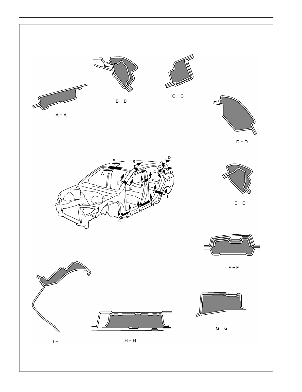
FOAMED MATERIAL APPLICATION AREAS
The sections shown in the figure below are filled with foamed material to provide noise insullation.
After repairing these sections or their peripheries, refill with foamed materials
HINT:
1) Use the service holes located on the reverse side of the body panel to refill with foamed materials.
2) When handling foamed material, follow the directions of the material’s manufacturer.
[Sedan]
F14415
[Liftback]
PAINT ! COATING
PC-13
F14417
PC-14
[Wagon]
PAINT ! COATING
F14416
PAINT ! COATING
PC-11
BODY PANEL UNDERCOATING AREAS
HINT:
1) First wipe off any dirt, grease or oil with a rag soaked in a grease, wax and silicone remover.
2) Cover the surrounding areas with masking paper to avoid coating unnecessary areas. If other areas are accidently coated, wipe off the coating immediately.
3) Apply the first coating of undercoat to all welded areas and panel joints, then apply a second coat over the
entire area.
4) Do not coat parts which become hot, such as the tailpipe, or moving parts, such as the propeller shaft.
5) Besides the locations described below, apply undercoating to all weld points under the body to insure corrosion prevention.
6) Be sure to seal the edge of the flange of the member and bracket with undercoating.
7) If undercoat is damaged by peeling, cracks, etc., be sure to repair as necessary.
8) Before the undercoat apply sealer allowing rust prevention to be attained.
REFERENCE
Referring to the notes above, undercoating should be applied according to the specifications for your country.
F14411

IN-18
INTRODUCTION
ABBREVIATIONS USED IN THIS MANUAL
For convenience, the following abbreviations are used in this
manual.
ABS Antilock Brake System
A/C Air Conditioner
assy assembly
ECT Electronic Controlled Transmission
ECU Electronic Control Unit
e.g. Exempli Gratia (for Example)
Ex. Except
FWD Front Wheel Drive Vehicles
4WD Four Wheel Drive Vehicles
in. inch
LH Left-hand
LHD Left-hand Drive
MIG Metal Inert Gas
M/Y Model Year
PPS Progressive Power Steering
RH Right-hand
RHD Right-hand Drive
SRS Supplemental Restraint System
SSM Special Service Materials
w/ with
w/o without
IN-16
INTRODUCTION
PRECAUTIONS FOR REPAIRING BODY
STRUCTURE PANELS
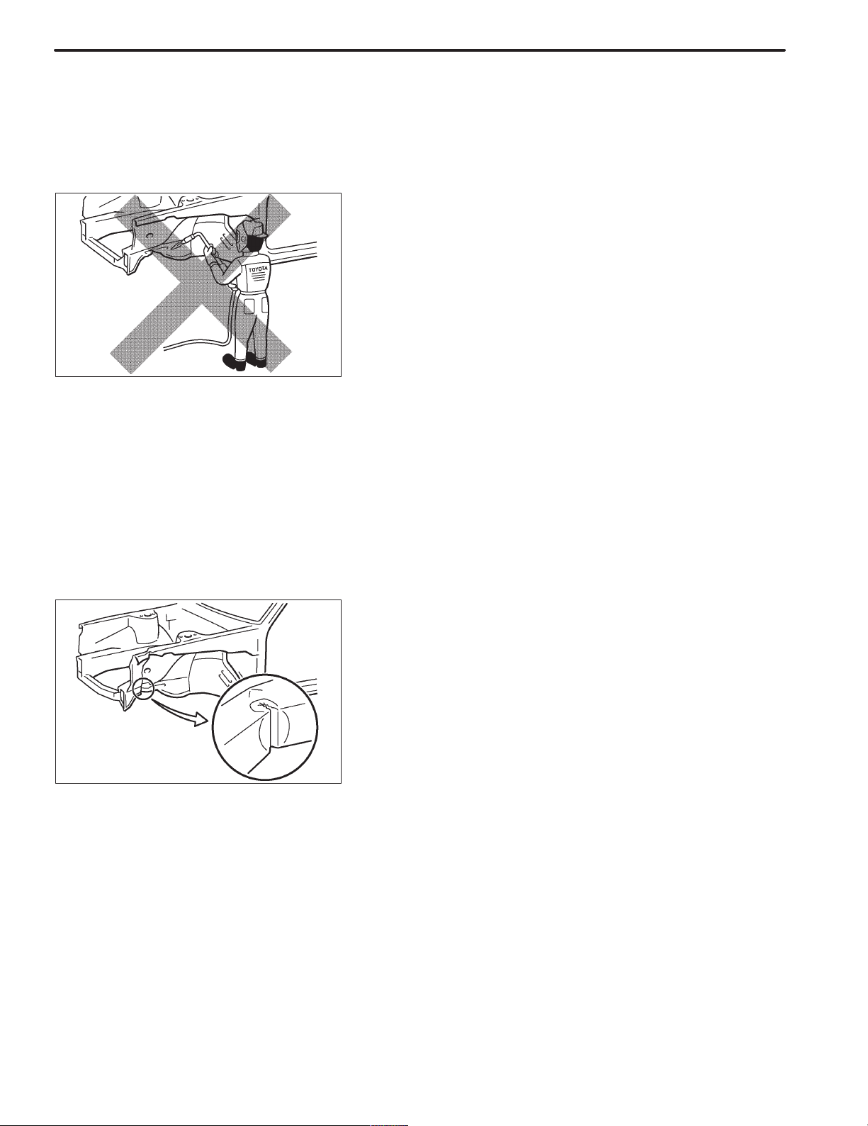
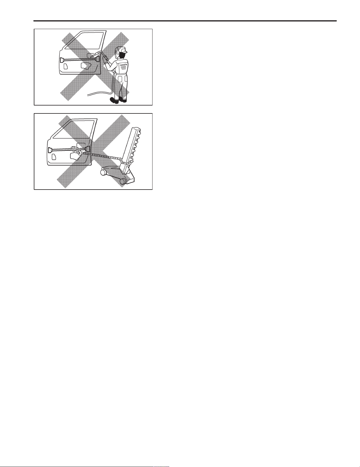
1. HEAT REPAIR FOR BODY STRUCTURE
PANELS
Toyota prohibits the use of the heat repair method on body
structure panels when repairing a vehicle damaged in a collision.
Panels that have high strength and rigidity, as well as a long
life span for the automobile body are being sought after.
At Toyota, in order to fulfill these requirement, we use high
tensile strength steel sheets and rust preventive steel
sheets on the body.
High tensile steel sheets are made with alloy additives and
a special heat treatment in order to improve the strength.
To prevent the occurrence of rust for a long period of time,
the surface of the steel is coated with a zinc alloy.
If a body structure parts are heat repaired with an acetylene
torch or other heating source, the crystalline organization of
the steel sheet will change and the strength of the steel
sheet will be reduced.
The ability of the body to resist rust is significantly lowered
as well since the rust resistant zinc coating is destroyed by
heat and the steel sheet surface is oxidized.
2. STRUCTURE PANEL KINKS
A sharp deformation angle on the panel that cannot be returned to its original shape by pulling or hammering is
called a kink.
Since structure parts were designed to exhibit a 100% performance when they were in their original shape, if they are
deformed in an accident, or if the deformed parts are repaired and reused, they become unable to exhibit the same
performance as intended in the design.
It is necessary to replace the part where the kink has occurred.
INTRODUCTION
3. IMPACT BEAM REPAIR
The impact beam and bracket are necessary and important
parts in maintaining a survival space for passengers in a
side collision.
For impact beam, we use special high tensile strength
steel.
The high tensile strength steel maintains its special crystalline organization by heat treatment or alloy additives.
Since these parts were designed to exhibit a 100% performance when they were in their original shape, if they are
deformed in an accident, or if the deformed parts are repaired and reused, they become unable to exhibit the same
performance as intended in the design.
It is necessary to replace the door assembly when impact
beam or bracket is damaged.
IN-17
INTRODUCTION
HANDLING PRECAUTIONS ON RELATED COMPONENTS
1. BRAKE SYSTEM
The brake system is one of the most important safety components. Always follow the directions and
notes given in section BR of the repair manual for the relevant model when handling brake system parts.
NOTICE: When repairing the brake master cylinder or TRAC system, bleed the air out of the TRAC system.
2. DRIVE TRAIN AND CHASSIS
The drive train and chassis are components that can have great effects on the running performance and
vibration resistance of the vehicle. After installing components in the sections listed in the table below,
perform alignments to ensure correct mounting angles and dimensions. Particularly accurate repair of
the body must also be done to ensure correct alignment.
HINT: Correct procedures and special tools are required for alignment. Always follow the directions given in the repair manual for the relevant model during alignment and section DI of this section.
IN-15
Component to be aligned
Front Wheels Front Suspension (26) section
Rear Wheels Rear Suspension (27) section
Section of repair manual
for relevant model
3. COMPONENTS ADJACENT TO THE BODY PANELS
Various types of component parts are mounted directly on or adjacently to the body panels. Strictly observe the following precautions to prevent damaging these components and the body panels during handling.
! Before repairing the body panels, remove their components or apply protective covers over the com-
ponents.
! Before prying components off using a screwdriver or a scraper, etc., attach protective tape to the tool
tip or blade to prevent damaging the components and the body paint.
! Before removing components from the outer surface of the body, attach protective tape to the body to
ensure no damage to painted areas.
HINT: Apply touch-up paint to any damaged paint surfaces.
! Before drilling or cutting sections, make sure that there are no wires, etc. on the reverse side.
4. ECU (ELECTRONIC CONTROL UNIT)
Many ECUs are mounted in this vehicle.
Take the following precautions during body repair to prevent damage to the ECUs.
! Before starting electric welding operations, disconnect the negative (–) terminal cable from the bat-
tery.
When the negative (–) terminal cable is disconnected from the battery, memory of the clock and audio
systems will be cancelled. So before starting work, make a record of the contents memorized by each
memory system. Then when work is finished, reset the clock and audio systems as before.
When the vehicle has tilt and telescopic steering, power seat and outside rear view mirror, which are
all equipped with memory function, it is not possible to make a record of the memory contents.
So when the operation is finished, it will be necessary to explain this fact to the customer, and request
the customer to adjust the features and reset the memory.
! Do not expose the ECUs to ambient temperatures above 80"C (176"F).
NOTICE: If it is possible the ambient temperature may reach 80"C (176"F) or more, remove the ECUs
from the vehicle before starting work.
! Be careful not to drop the ECUs and not to apply physical shocks to them.
IN-10
Cutting Okay
Reinforcement
INTRODUCTION
PROPER AND EFFICIENT WORK
PROCEDURES
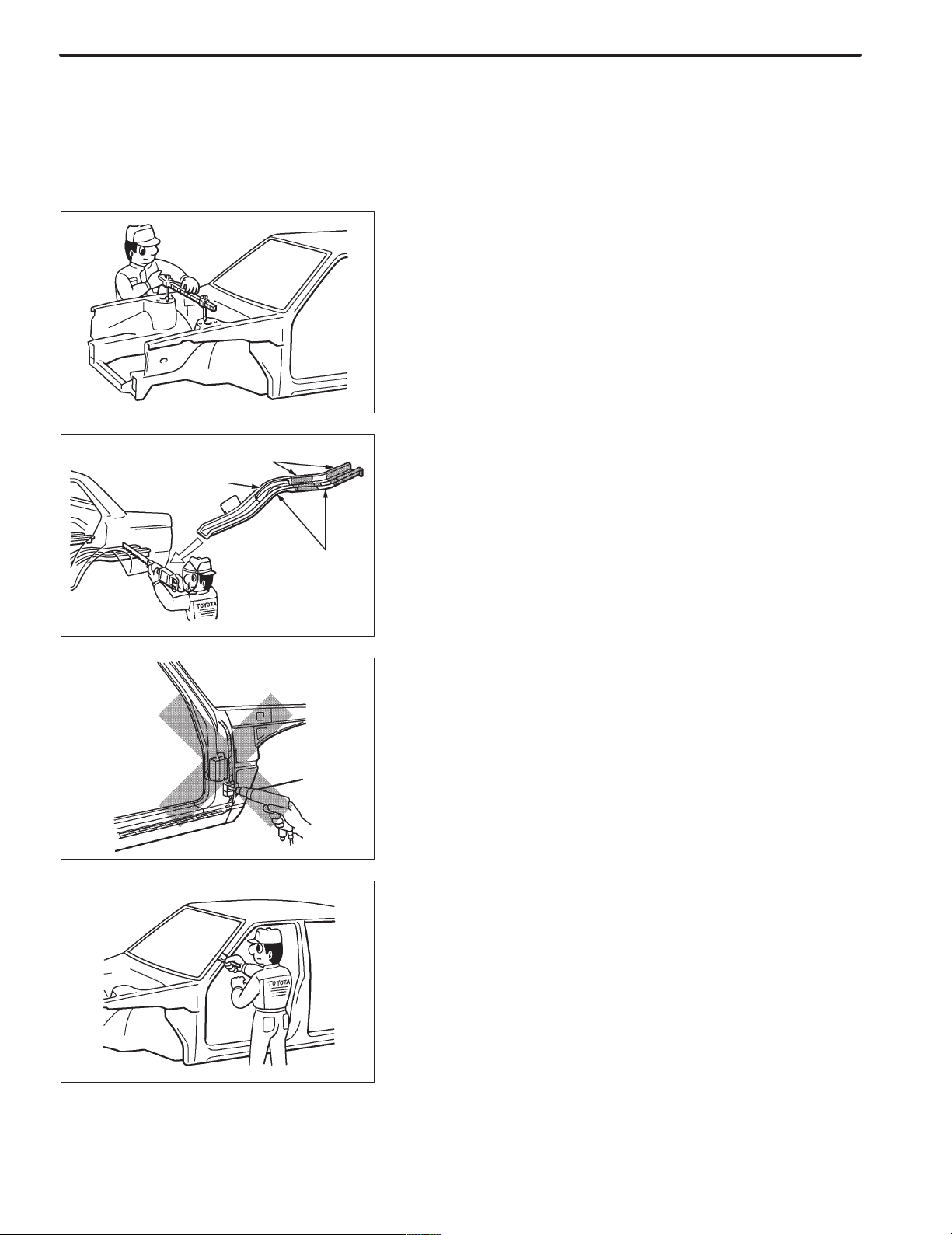
1. REMOVAL
(a) PRE-REMOVAL MEASURING
(1) Before removal or cutting operations, take measure-
ments in accordance with the dimension diagram. Always use a puller to straighten a damaged body or
frame.
F10007
(b) CUTTING AREA
(1) Always cut in a straight line and avoid reinforced area.
WRONG
Corners
F10008A
(c) PRECAUTIONS FOR DRILLING OR CUTTING
(1) Check behind any area to be drilled or cut to insure
that there are no hoses, wires, etc., that may be damaged.
HINT: See “Handling Precautions on Related Components” on page IN-15.
F10009A
(d) REMOVAL OF ADJACENT COMPONENTS
(1) When removing adjacent components, apply protec-
tive tape to the surrounding body and your tools to prevent damage.
HINT: See “Handling Precautions on Related Components” on page IN-15.
F10010
Less than
3mm
F10011A
F10012
INTRODUCTION
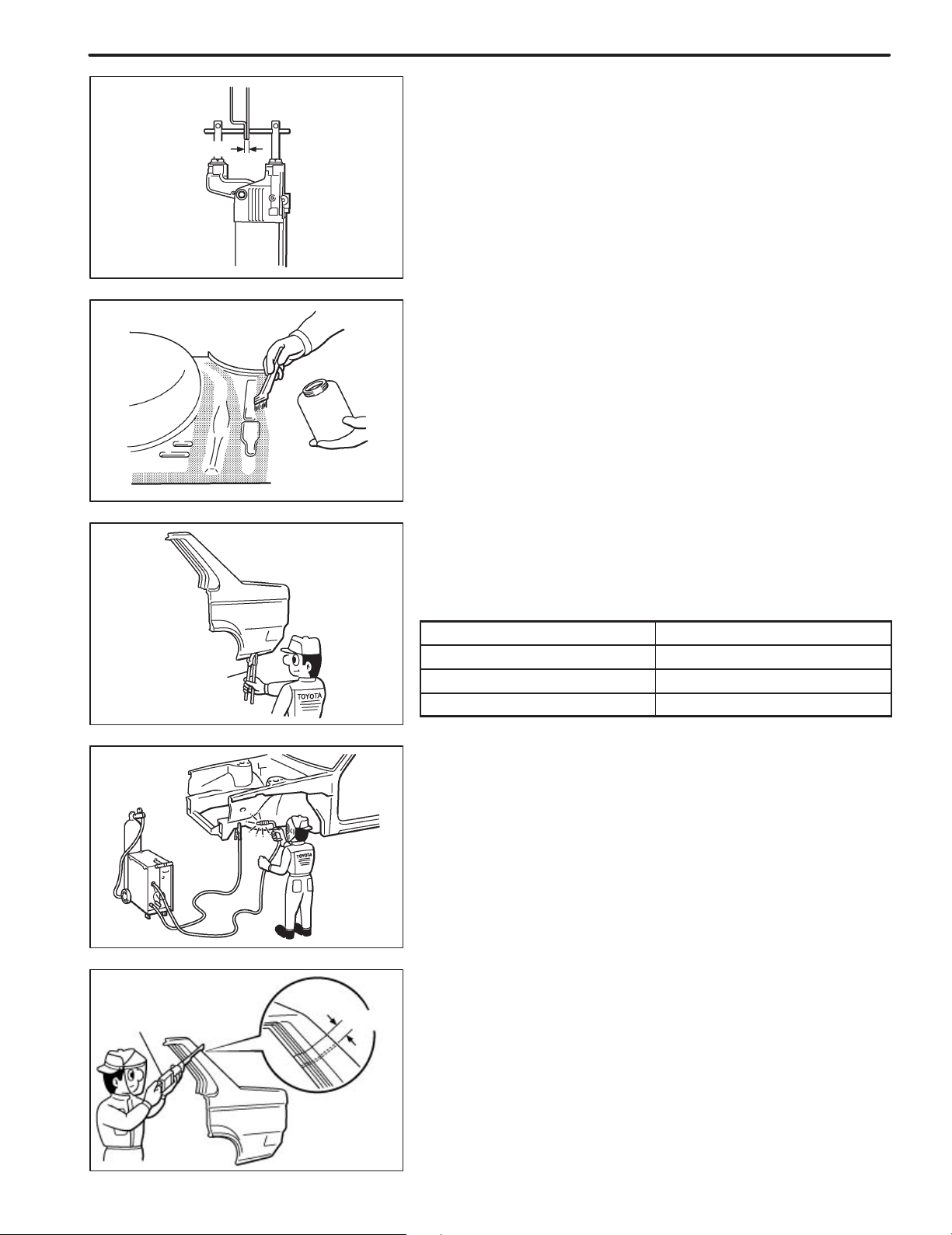
2. PREPARATION FOR INSTALLATION
(a) SPOT WELD POINTS
(1) When welding panels with a combined thickness of
over 3mm (0.12in.), use a MIG (Metal Inert Gas) welder for plug welding.
HINT: Spot welding will not provide sufficient durability
for panels over 3mm (0.12in.) thick.
(b) APPLICATION OF WELD-THROUGH PRIMER
(SPOT SEALER)
(1) Remove the paint from the portion of the new parts
and body to be welded, and apply weld-through primer.
IN-11
Air Saw
Puncher
20 ! 30mm
F10013A
F10014
Overlap
(c) MAKING HOLES FOR PLUG WELDING
(1) For areas where a spot welder cannot be used, use a
puncher or drill to make holes for plug welding.
REFERENCE: mm (in.)
Thickness of welded portion Size of plug hole
1.0 (0.04) under 5 (0.20) ø over
1.0 (0.04) – 1.5 (0.06) 6.4 (0.26) ø over
1.5 (0.06) over 8 (0.31) ø over
(d) SAFETY PRECAUTIONS FOR ELECTRICAL COM-
PONENTS
(1) When welding, there is a danger that electrical compo-
nents will be damaged by the electrical current flowing
through the body.
(2) Before starting work, disconnect the negative terminal
of the battery and ground the welder near the welding
location of the body.
(e) ROUGH CUTTING OF JOINTS
(1) For joint areas, rough cut the new parts, leaving 20 –
30mm (0.79 – 1.18in.) overlap.
F10015A
IN-12
Body
Measurement
Diagrams
INTRODUCTION
3. INSTALLATION
(a) PRE-WELDING MEASUREMENTS
(1) Always take measurements before installing under-
body or engine components to insure correct assembly. After installation, confirm proper fit.
F10016A
(b) WELDING PRECAUTIONS
(1) The number of welding spots should be as follows.
Spot weld: 1.3 X No. of manufacturer’s spots.
Plug weld: More than No. of manufacturer’s plugs.
(2) Plug welding should be done with a MIG (Metal Inert
Gas) welder. Do not gas weld or braze panels at areas
other than specified.
WRONG
CORRECT WRONG
Tip Cutter
F10017A
(c) POST-WELDING REFINISHING
(1) Always check the welded spots to insure they are se-
cure.
(2) When smoothing out the weld spots with a disc grind-
er, be careful not to grind off too much as this would
weaken the weld.
F10018A
(d) SPOT WELD LOCATIONS
(1) Try to avoid welding over previous spots.
F10019A
Old
Spot
Locations
New Spot
Locations
F10020A
(e) SPOT WELDING PRECAUTIONS
(1) The shape of the welding tip point has an effect on the
strength of the weld.
(2) Always insure that the seams and welding tip are free
of paint.
INTRODUCTION
IN-13
Sealer Gun
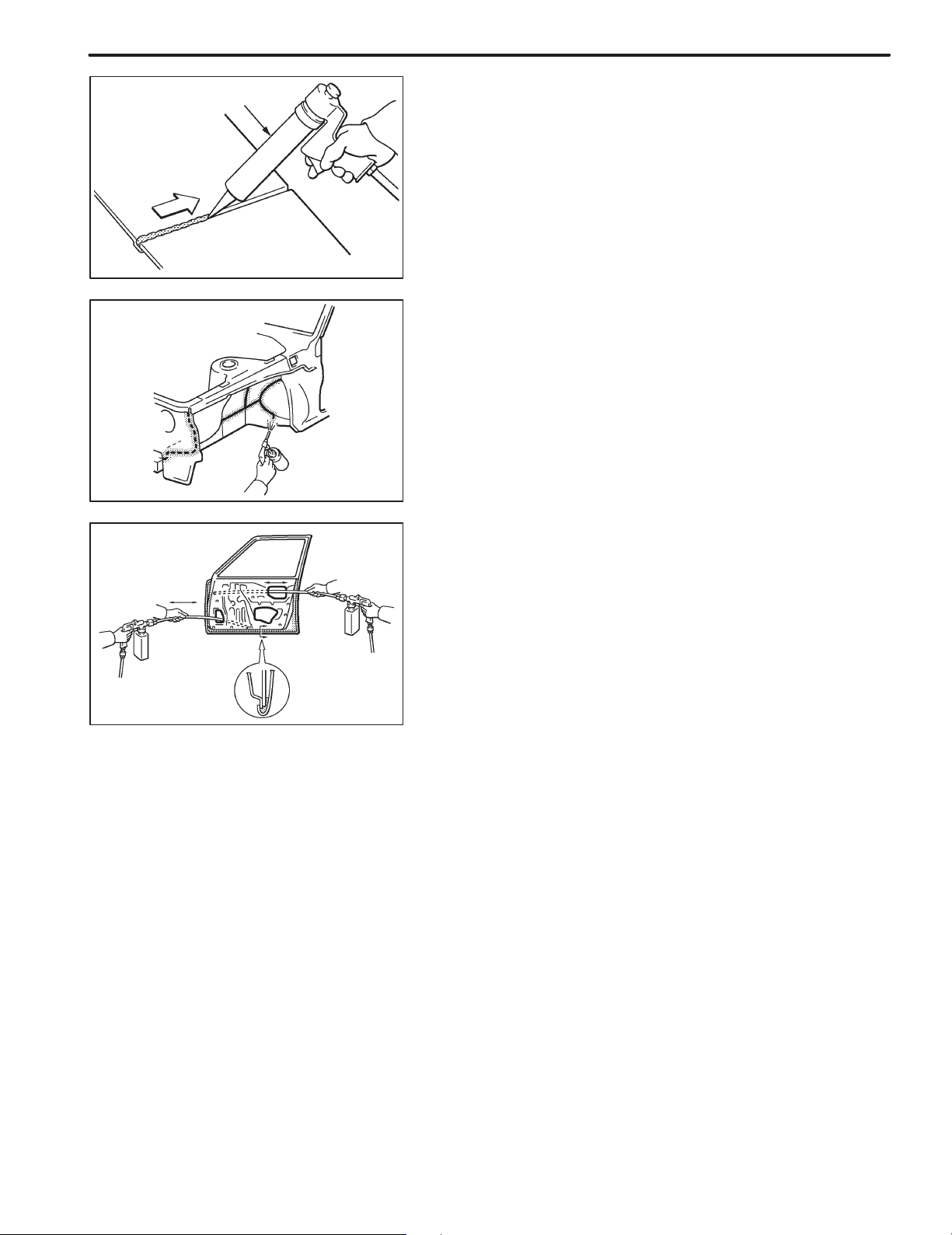
4. ANTI-RUST TREATMENT
(a) BODY SEALER APPLICATION
(1) For water-proofing and anti-corrosion measures, al-
ways apply the body sealer to the body panel seams
and hems of the doors, hoods, etc.
F10021A
(b) UNDERCOAT APPLICATION
(1) To prevent corrosion and protect the body from dam-
age by flying stones, always apply sufficient undercoat to the bottom surface of the under body and inside of the wheel housings.
F10022
5. ANTI-RUST TREATMENT AFTER PAINTING
PROCESS
(a) ANTI-RUST AGENT (WAX) APPLICATION
(1) To preserve impossible to paint areas from corrosion,
always apply sufficient anti-rust agent (wax) to the inside of the hemming areas of the doors and hoods,
and around the hinges, or the welded surfaces inside
the boxed cross-section structure of the side member,
body pillar, etc.
F10023
IN-14
INTRODUCTION
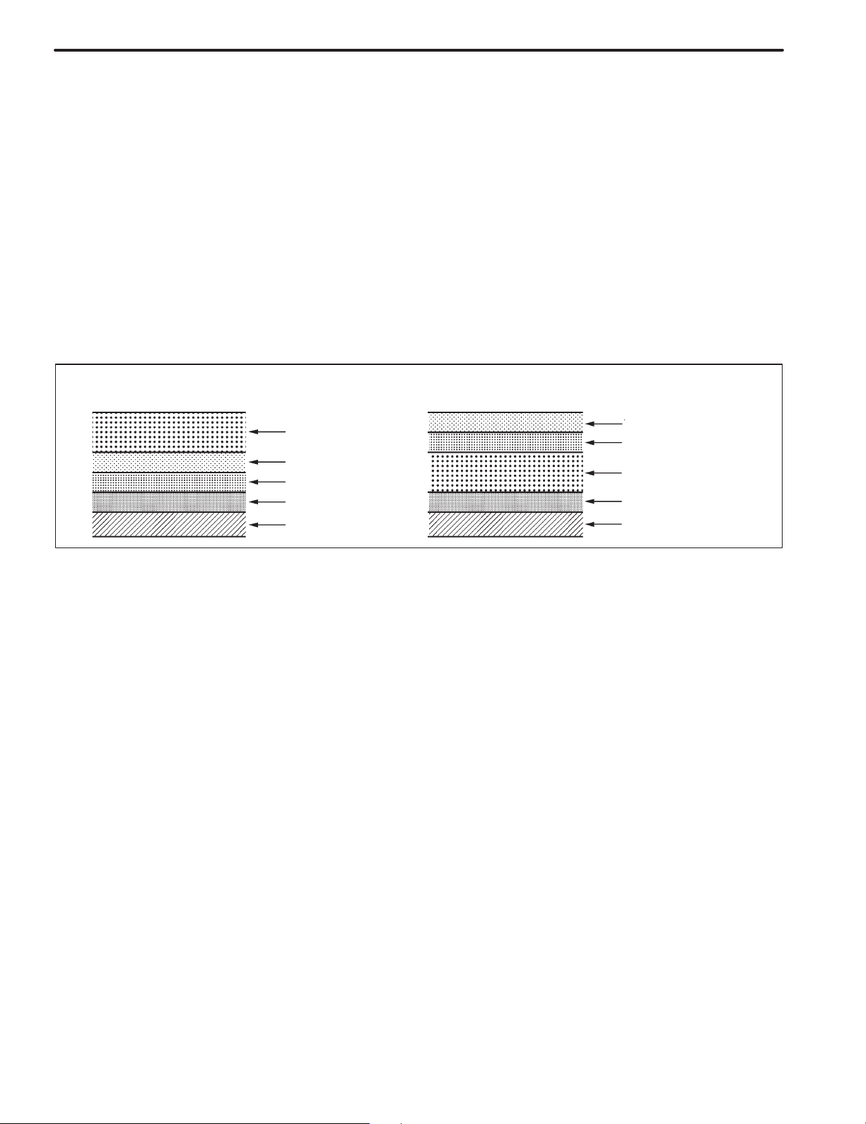
6. ANTI-RUST TREATMENT BY PAINTING
REFERENCE:
Painting prevents corrosion and protect the sheet
metal from damage. In this section, anti-chipping paint
only for anti-corrosion purpose is described.
(a) ANTI-CHIPPING PAINT
(1) To prevent corrosion and protect the body from dam-
age by flying stones, etc., apply anti-chipping paint to
the rocker panel, wheel arch areas, balance panel,
etc.
HINT:
Depending on the model or the application area, there
are cases where the application of anti-chipping paint
is necessary before the second coat or after the top
coat.
! Apply the anti-chipping paint after
the top coat.
Anti-Chipping Paint
Top Coat
Second Coat
Under Coat (ED Primer)
Steel Metal
! Apply the anti-chipping paint before
the second coat.
Top Coat
Second Coat
Anti-Chipping Paint
Under Coat (ED Primer)
Steel Metal
F10024A
INTRODUCTION
HOW TO USE THIS MANUAL
1. BODY PANEL REPLACEMENT THIS MANUAL
IN-5
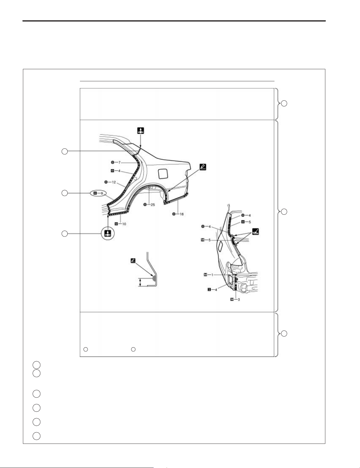
BP-34
QUARTER PANEL (CUT)
A
REMOVAL
B
D
BODY PANEL REPLACEMENT
C
I
K
A
I
POINT
1 Remove the at the same time.
E
PART NAME
A
Fuel Filler Opening Lid
:
REPLACEMENT PART AND METHOD
A
A
QUARTER PANEL (CUT)
Replacement method
(ASSY) ... Assembly replacement
(CUT) ... Major cutting (less than 1/2 of part used)
(CUT-H) ... Half cutting (about 1/ 2 of part used)
(CUT-P) ... Partial cutting (most of part used)
Replacement part
:
REMOVAL CONDTIONS
B
:
PART LOCATION
C
:
REMOVAL DIAGRAM
D
Describes in detail removal of the damaged part involving repair by cutting.
:
REMOVAL GUIDE
E
Provides additional information to more efficiently help you perform the removal.
J
F13890A
IN-6
INTRODUCTION
BODY PANEL REPLACEMENT BP-35
INSTALLATION
! Temporaily install the new parts and measure each p art of the new parts in accordance with the body dimension
diagram. (See the body dimension dia gram)
! Inspec t the fi ting of the rela ted part s aroun d the new pa rts befo re w elding. Thi s aff ects the appear ance of the
finish.
! After welding, apply the polyurethane foam to the corresponding parts.
! After welding, apply body sealer and under-coating to the corresponding parts.
! After applying the top coat layer, apply anti-rust agent to the inside of the necked section structural weld spots.
I
F
J
G
I
5mm
POINT
1 Before temporarily installing the new parts, apply body sealer to the wheel arch.
HINT:
1) Apply body sealer about 5mm (0.20in.) front the flange, avoiding any oozing.
2) Apply sealer evenly, about 3 – 4mm (0.12 – 0.16in.) in diameter.
3) For other sealing points, refer to section PC.
PART NAME
A B
Fuel Filler Opening Lid Waterproof Rivet
H
:
INSTALLATION CONDITIONS
F
:
INSTALLATION DIAGRAM
G
Describes in detail installation to the new part involving repair by welding and/ or
cutting, but excluding painting.
:
INSTALLATIOLN GUIDE
H
Provides additional information to more efficiently help you perform the installation.
:
SYMBOLS
I
(See page IN-7)
:
ILLUSTRATION OF WELD POINTS
J
Weld method and panel position symbols (See page IN-9)
:
PART NAME
K
F13891A
INTRODUCTION
IN-7
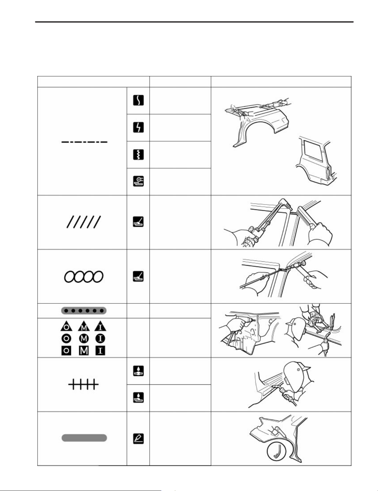
2. SYMBOLS
The following symbols are used in the welding diagrams in section BP of this manual to indicate cutting areas
and the types of weld required.
SYMBOLS MEANING ILLUSTRATION
CUT AND JOIN LOCATION
(SAW CUT)
CUT AND JOIN LOCATION
(Cut Location for
Supply Parts)
CUT LOCATION
CUT WITH DISC
SANDER, ETC.
—
—
BRAZE
(Removal)
BRAZE
(Installation)
WELD POINTS
SPOT WELD OR
MIG PLUG WELD
(See Page IN-9)
CONTINUOUS
MIG WELD
(BUTT WELD)
CONTINUOUS
MIG WELD
(TACK WELD)
BODY SEALER
F13893A
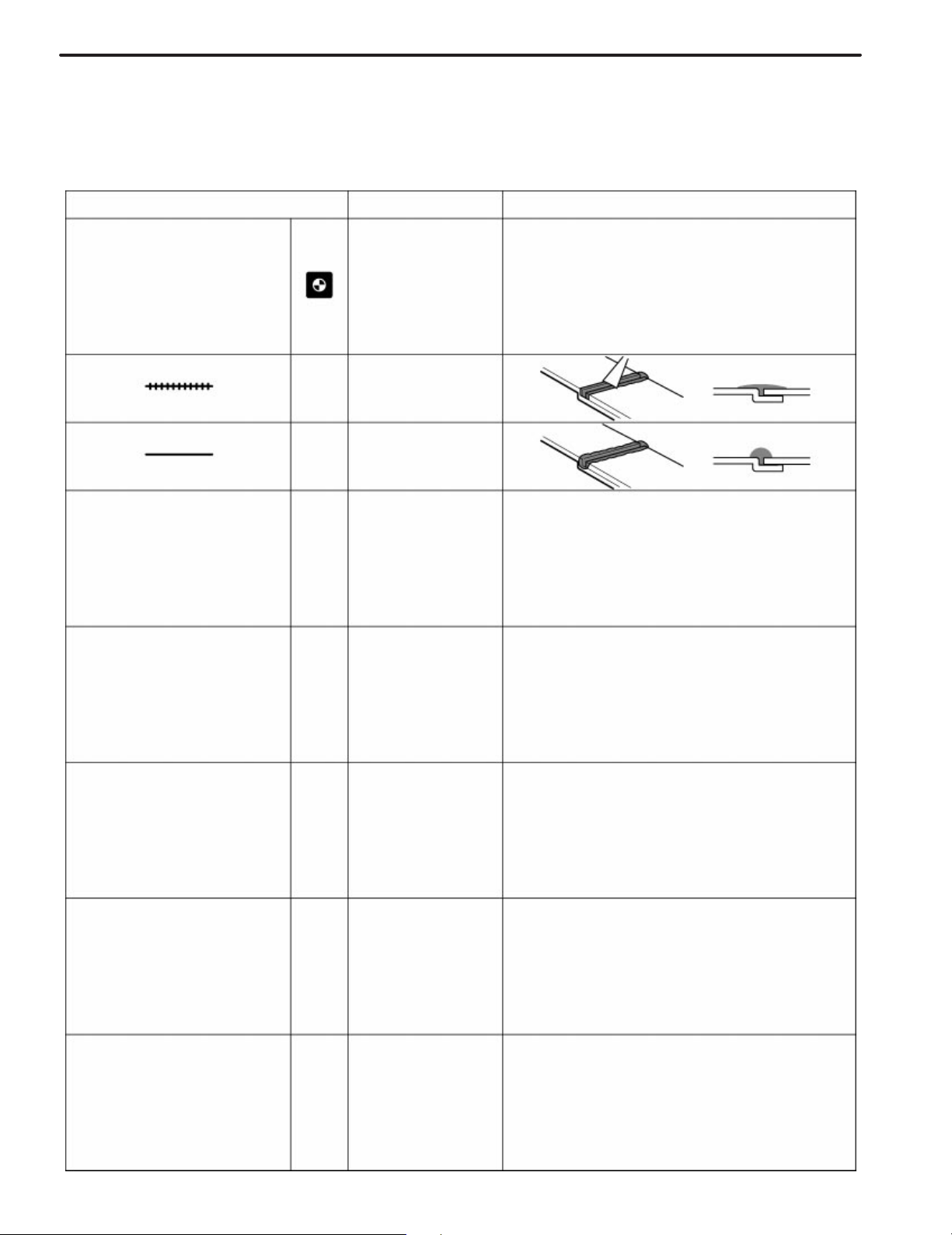
IN-8
INTRODUCTION
SYMBOLS MEANING ILLUSTRATION
—
—
—
Assembly Mark
BODY SEALER
(Flat Finishing)
BODY SEALER
(No flat Finishing)
F13894A
INTRODUCTION
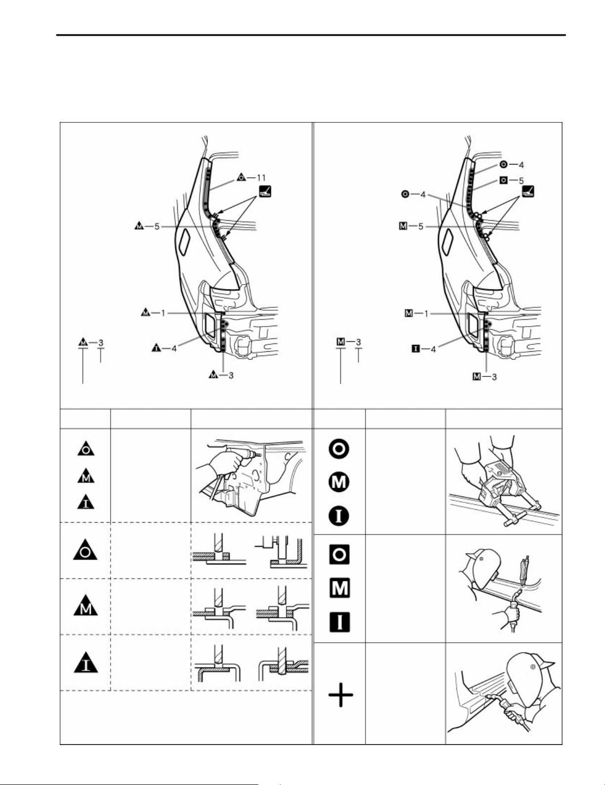
3. ILLUSTRATION OF WELD POINT SYMBOLS
EXAMPLE:
REMOVAL INSTALLATION
IN-9
Weld points
Remove weld point and panel position
SYMBOLS
MEANING ILLUSTRATION SYMBOLS MEANING ILLUSTRATION
Remove
Weld
Points
(Outside)
(Middle)
Weld points
Weld method and panel position
Spot Weld
MIG Plug
Weld
(Inside)
HINT: Panel position symbols are as seen from
the working posture.
Spot MIG
Weld
F13892A
Glass Cover
INTRODUCTION
GENERAL REPAIR INSTRUCTIONS
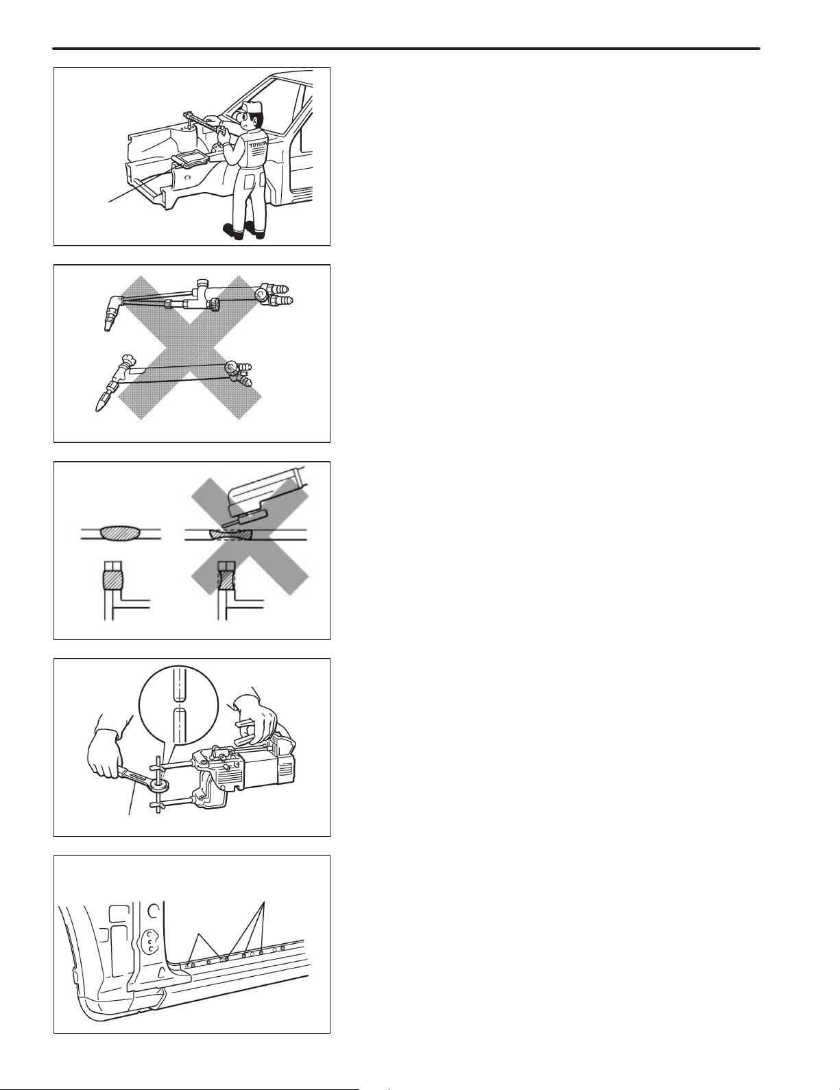
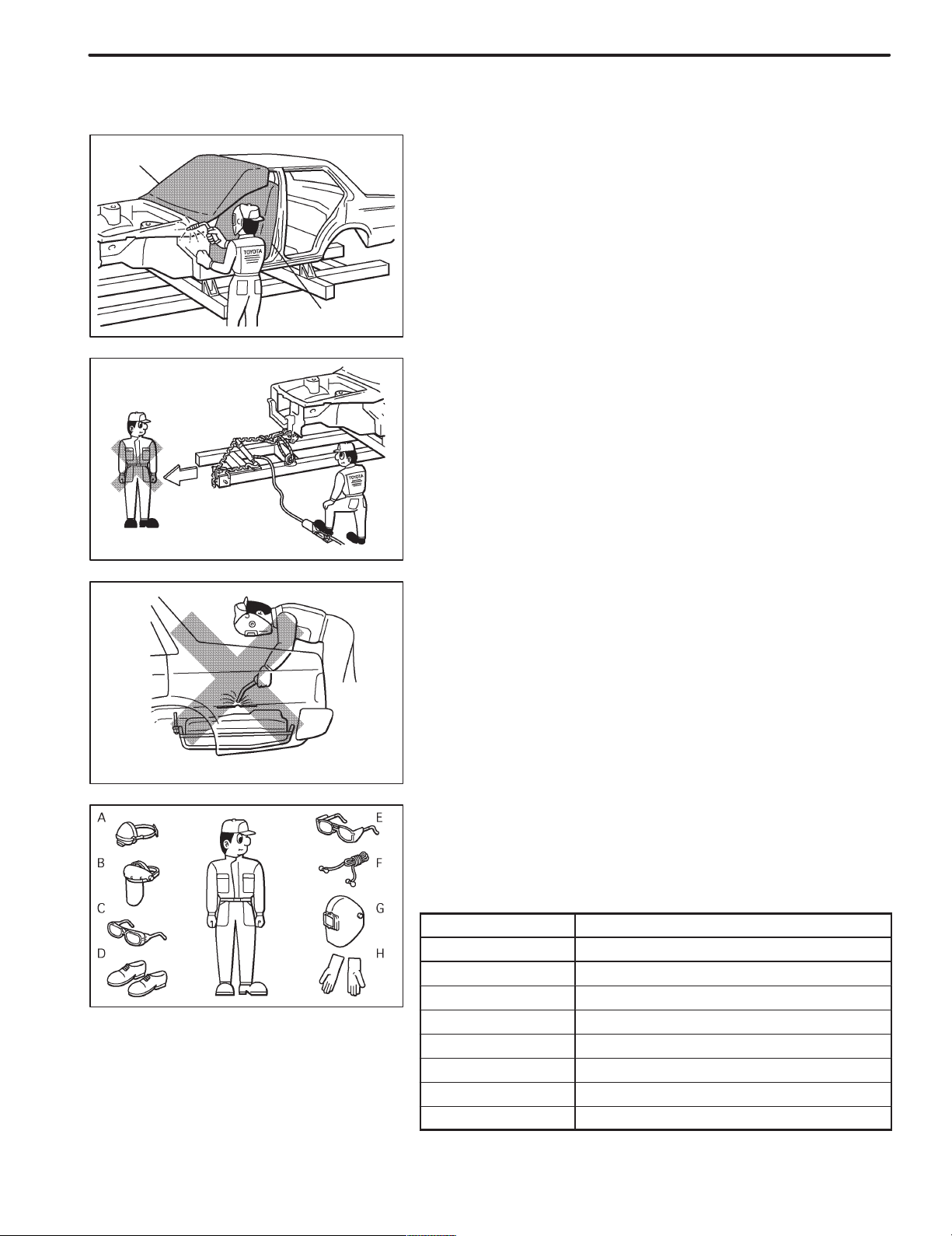
1. WORK PRECAUTIONS
(a) VEHICLE PROTECTION
(1) When welding, protect the painted surfaces, windows,
seats and carpet with heat resistant, fire-proof covers.
IN-1
WRONG
Seat Cover
F10001A
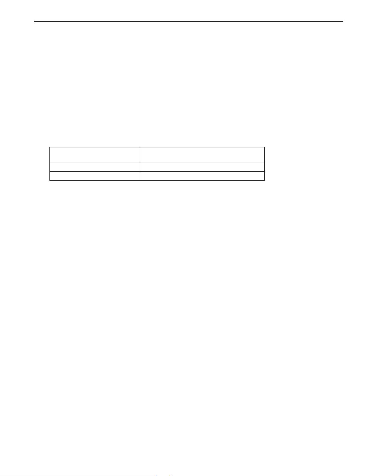
(b) SAFETY
(1) Never stand in direct line with the chain when using a
puller on the body or frame, and be sure to attach a
safety cable.
F10002A
(2) Before performing repair work, check for fuel leaks.
If a leak is found, be sure to close the opening totally.
(3) If it is necessary to use a flame in the area of the fuel
tank, first remove the tank and plug the fuel line.
WRONG
F10003A
F10004
(c) SAFETY WORK CLOTHES
(1) In addition to the usual mechanic’s wear, cap and
safety shoes, the appropriate gloves, head protector,
glasses, ear plugs, face protector, dust-prevention
mask, etc. should be worn as the situation demands.
Code Name
A Dust-Prevention Mask
B Face Protector
C Eye Protector
D Safety Shoes
E Welder’s Glasses
F Ear Plugs
G Head Protector
H Welder’s Gloves

IN-2
INTRODUCTION
2. HANDLING PRECAUTIONS OF PLASTIC BODY PARTS
(1) The repair procedure for plastic body parts must conform with the type of plastic material.
(2) Plastic body parts are identified by the codes in the following table.
(3) When repairing metal body parts adjoining plastic body parts (by brazing, frame cutting, welding, paint-
ing etc.), consideration must be given to the property of the plastic.
*
Heat
Code
Material
name
resistant
temperature
limit !C (!F)
Resistance to
alcohol or gasoline
Notes
AAS
ABS
AES
ASA
CAB
EPDM
FRP
Acrylonitrile
Acrylic Styrene
Acrylonitrile
Butadiene Styrene
Acrylonitrile
Ethylene Styrene
Acrylonitrile
Styrene
Acrylate
Cellulose
Acetate
Ethylene
Propylene
Fiber
Reinforced
Plastics
80
(176)
80
(176)
80
(176)
80
(176)
80
(176)
100
(212)
180
(356)
Alcohol is harmless if applied only for
short time in small amounts (e.g., quick
wiping to remove grease).
Alcohol is harmless if applied only for
short time in small amounts (e.g., quick
wiping to remove grease).
Alcohol is harmless if applied only for
short time in small amounts (e.g., quick
wiping to remove grease).
Alcohol is harmless if applied only for
short time in small amounts (e.g., quick
wiping to remove grease).
Alcohol is harmless if applied only for
short time in small amounts (e.g., quick
wiping to remove grease).
Alcohol is harmless.
Gasoline is harmless if applied only for
short time in small amounts.
Alcohol and gasoline are harmless. Avoid alkali.
Avoid gasoline and organic
or aromatic solvents.
Avoid gasoline and organic
or aromatic solvents.
Avoid gasoline and organic
or aromatic solvents.
Avoid gasoline and organic
or aromatic solvents.
Avoid gasoline and organic
or aromatic solvents.
Most solvents are harmless
but avoid dipping in gasoline,
solvents, etc.
EVA
PA
PBT
PC Polycarbonate
*Temperatures higher than those listed here may result in material deformation during repair.
Ethylene
Acetate
Polyamide
(Nylon)
Polybutylene
Terephthalate
70
(158)
80
(176)
160
(320)
120
(248)
Alcohol is harmless if applid only for short
time in small amounts (e.g., quick wiping
to remove grease).
Alcohol and gasoline are harmless. Avoid battery acid.
Alcohol and gasoline are harmless. Most solvents are harmless.
Alcohol is harmless.
Avoid gasoline and organic
or aromatic solvents.
Avoid gasoline brake fluid,
wax, wax removers and
organic solvents. Avoid alkali.

Code
Material
name
*
Heat
resistant
temperature
limit !C (!F)
INTRODUCTION
Resistance to
alcohol or gasoline
IN-3
Notes
PE Polyethylene
PET
PMMA
POM
PP Polypropylene
PPO
PS Polystyrene
PUR Polyurethane
Polyethylene
Terephthalate
Polymethyl
Methacrylate
Polyoxymethylene
(Polyacetal)
Modified
Polyphenylene
Oxide
80
(176)
75
(167)
80
(176)
100
(212)
80
(176)
100
(212)
60
(140)
80
(176)
Alcohol and gasoline are harmless. Most solvents are harmless.
Alcohol and gasoline are harmless. Avoid dipping in water.
Alcohol is harmless if applied only for
short time in small amounts.
Alcohol and gasoline are harmless. Most solvents are harmless.
Alcohol and gasoline are harmless. Most solvents are harmless.
Alcohol is harmless.
Alcohol and gasoline are harmless if
applied only for short time in small
amounts.
Alcohol is harmless if applied only for very
short time in small amounts (e.g., quick
wiping to remove grease).
Avoid dipping or immersing
in alcohol, gasoline,
solvents, etc.
Gasoline is harmless if
applied only for quick wiping
to remove grease.
Avoid dipping or immersing
in alcohol, gasoline,
solvents, etc.
Avoid dipping or immersing
in alcohol, gasoline,
solvents, etc.
Alcohol and gasoline are harmless if
PVC
SAN
TPO
TPU
TSOP
UP
*Temperatures higher than those listed here may result in material deformation during repair.
Polyvinylchloride
(Vinyl)
Styrene
Acrylonitrile
Thermoplastic
Olefine
Thermoplastic
Polyurethane
TOYOTA
Super
Olefine Polymer
Unsaturated
Polyester
80
(176)
80
(176)
80
(176)
80
(176)
80
(176)
110
(233)
applied only for short time in small
amounts (e.g., quick wiping to remove
grease).
Alcohol is harmless if applied only for
short time in small amounts (e.g., quick
wiping to remove grease).
Alcohol is harmless.
Gasoline is harmless if applied only for
short time in small amounts.
Alcohol is harmless if applied only for
short time in small amounts (e.g., quick
wiping to remove grease).
Alcohol and gasoline are harmless. Most solvents are harmless.
Alcohol and gasoline are harmless. Avoid alkali.
Avoid dipping or immersing
in alcohol, gasoline,
solvents, etc.
Avoid dipping or immersing
in alcohol, gasoline, solvents
etc.
Most solvents are harmless
but avoid dipping in gasoline,
solvents, etc.
Avoid dipping or immersing
in alcohol, gasoline,
solvents, etc.

IN-4
INTRODUCTION
3. LOCATION OF PLASTIC BODY PARTS
Parts Name Code
Radiator Grille ABS/ASA
Front Bumper Cover TSOP
Front Spoiler TSOP
Front Bumper Side Moulding TSOP
Headlight Washer Nozzle Cover PC/ABS
Headlight PC/PP
Fog light PP
Side Turn Signal Light PMMA/ABS
Outer Rear View Mirror ASA
Roof Rack Leg Cover (Wagon Only) ABS
Door Outside Handle PC/PBT/ PA
Door Outside Moulding PP /EPDM
Body Rocker Panel Moulding PP
Rear Combination Light PMMA/PC / ABS
Rear Spoiler (Wagon Only) ABS
Center Stop Light (Wagon Only) PMMA/ABS
Luggage Compartment Door Outside Garnish ABS
License Plate Light PMMA/ABS
Rear Bumper Cover TSOP
Rear Bumper Side Moulding TSOP
! Resin material differs with model.
/ Made up of 2 or more kinds of materials.
BODY DIMENSIONS
BODY DIMENSION DRAWINGS
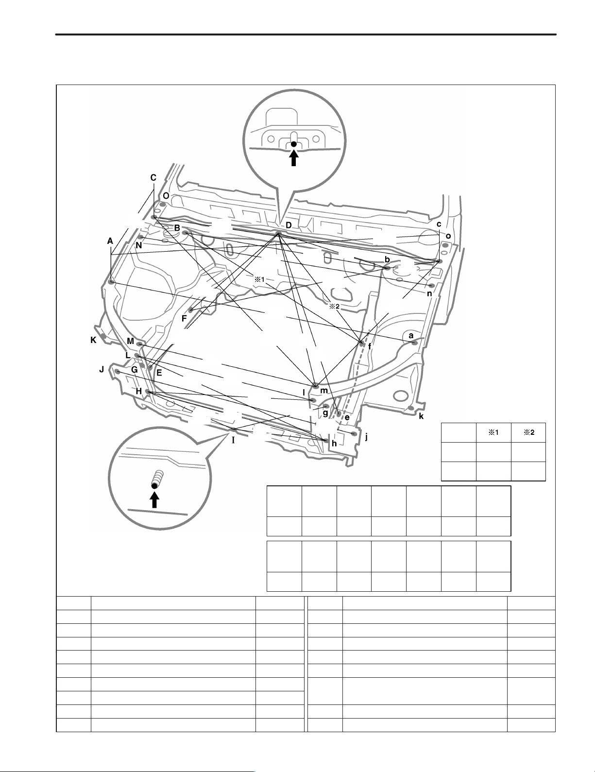
ENGINE COMPARTMENT
(Three-Dimensional Distance)
DI-3
467
(18.39)
851
(33.50)
854
(33.62)
647
(25.47)
(29.92)
444
(17.48)
760
1,427
(56.18)
760
(29.92)
838
(32.99)
1,478
(58.19)
1,038
(40.87)
834
1,089
(42.87)
523
(20.59)
(6.27)
817
(32.17)
210
Engine
Model
ZZ, CD
1,410
(55.51)
1,323
(52.09)
874
(34.41)
422
(16.61)
1,378
(54.25)
(40.28)
768
(30.24)
537
(21.14)
1,023
(32.83)
Vehicle Dimensions
B-c C-n C-N C-O
or or or or G-g G-h g-H
b-C c-N c-n c-o
1,227 1,428 159 113 828 854 876
(48.31) (56.22) (6.26) (4.45) (32.60) (33.62) (34.49)
AZ
1,022 625
(40.24) (24.61)
1,010 606
(39.76) (23.86)
I-j I-J J-L j-l K-k or or
593 607 250 240 1,439 1,452 272
(23.35) (23.90) (9.84) (9.45) (56.65) (57.17) (10.71)
N-o N-O
n-O n-o
mm (in.)
Symbol Name Hole dia. Symbol Name Hole dia.
A, a
B, b
C, c
E, e
G, g
H, h
Front fender installation nut
Front spring support hole-inner
Front fender installation nut
D
Cowl top inner panel standard hole
Front side member standard hole
F,
Front side member standard hole
f
Engine mounting installation nut
Radiator support standard hole
Front crossmember side gusset standard hole
6 (0.24) nut
11 (0.43)
6 (0.24) nut
—
18 (0.71)
12 (0.47)
10 (0.39) nut
10 (0.39)
10 (0.39)
I
J, j
K, k
L, l
M, m
N, n
O, o
—
Hood lock brace installation bolt
Front side member rear plate standard hole
Front fender extention standard hole
Radiator upper support installation nut
Radiator upper support installation nut
Front apron to cowl side upper member
standard hole
Hood hinge installation nut
—
6 (0.24) bolt
13 (0.51)
7 (0.28)
6 (0.24) nut
6 (0.24) nut
10 (0.39)
8 (0.31) nut
—

DI-4
BODY DIMENSIONS
BODY OPENING AREAS (Side View: Front)
All
(Three-Dimensional Distance)
1,097
(43.19)
874
(34.41)
1,286
(50.63)
1,475
(58.07)
(35.91)
866
(34.09)
845
(33.27)
912
1,219
(47.99)
1,096
(43.15)
995
(39.17)
831
(32.72)
1,053
(41.46)
Vehicle Dimensions Left ! Right
E-e F-f G-g H-h I-i J-j K-k
1,323 1,411 1,419 1,419 1,157 1,265 1,420
(52.09) (55.55) (55.87) (55.87) (45.55) (49.80) (55.91)
E-f E-h E-j F-j F-k H-i J-k
or or or or or or or
e-F e-H e-J f-J f-K h-I j-K
1,493 1,621 1,545 1,808 1,641 1,622 1,540
(58.78) (63.82) (60.83) (71.18) (64.61) (63.86) (60.63)
mm (in.)
Symbol Name Hole dia. Symbol Name Hole dia.
A, a
B, b
C, c
D, d
E, e
G, g
Roof panel corner
Wiper link installation nut
Front door hinge installation nut
Front door hinge installation nut
Front body pillar assembly mark
F, f
Front body pillar assembly mark
Rocker panel assembly mark
—
6 (0.24) nut
8 (0.31) nut
8 (0.31) nut
—
—
—
H, h
I,i
J, j
K, k
L, l
M, m
—
Rocker panel assembly mark
Roof side rail assembly mark
Center body pillar assembly mark
Center body pillar assembly mark
Rear door hinge installation nut
Rear door hinge installation nut
—
—
—
—
—
8 (0.31) nut
8 (0.31) nut
—

BODY DIMENSIONS
BODY OPENING AREAS (Side View: Rear)
Sedan, Liftback
(Three-Dimensional Distance)
884
(34.80)
(39.80)
1,011
812
(31.97)
1,106
(43.54)
1,052
(41.42)
DI-5
667
(26.26)
Vehicle Dimensions Left ! Right
N-n O-o P-p Q-q R-r S-s
1,267 1,420 1,419 1,151 1,309 1,409
(49.88) (55.91) (55.87) (45.31) (51.54) (55.47)
G-p I-q N-r N-s O-s P-q R-s
or or or or or or or
g-P i-Q n-R n-S o-S p-Q r-S
1,759 1,338 1,522 1,602 1,564 1,630 1,496
(69.25) (52.68) (59.92) (63.07) (61.57) (64.17) (58.90)
mm (in.)
Symbol Name Hole dia. Symbol Name Hole dia.
G, g
N, n
O, o
Rocker panel assembly mark
I,i
Roof side rail assembly mark
Center body pillar assembly mark
Center body pillar assembly mark
—
—
—
—
P, p
Q, q
R, r
S, s
Rocker panel assembly mark
Roof side rail assembly mark
Quarter panel assembly mark
Quarter panel assembly mark
—
—
—
—

DI-6
BODY DIMENSIONS
BODY OPENING AREAS (Side View: Rear)
Wagon
(Three-Dimensional Distance)
884
(34.80)
1,021
(40.20)
852
(33.54)
1,136
(44.72)
1,075
(42.32)
667
(26.26)
Vehicle Dimensions Left ! Right
N-n O-o P-p Q-q R-r S-s
1,267 1,420 1,419 1,140 1,311 1,409
(49.88) (55.91) (55.87) (44.88) (51.61) (55.47)
G-p I-q N-r N-s O-s P-q R-s
or or or or or or or
g-P i-Q n-R n-S o-S p-Q r-S
1,759 1,333 1,545 1,602 1,564 1,631 1,502
(69.25) (52.48) (60.83) (63.07) (61.57) (64.21) (59.13)
mm (in.)
Symbol Name Hole dia. Symbol Name Hole dia.
G, g
N, n
O, o
Rocker panel assembly mark
I,i
Roof side rail assembly mark
Center body pillar assembly mark
Center body pillar assembly mark
—
—
—
—
P, p
Q, q
R, r
S, s
Rocker panel assembly mark
Roof side rail assembly mark
Quarter panel assembly mark
Quarter panel assembly mark
—
—
—
—

BODY DIMENSIONS
BODY OPENING AREAS (Rear View)
Sedan
(Three-Dimensional Distance)
1,047
(41.22)
1,295
(50.98)
1,048
(41.26)
1,236
(48.66)
1,233
(48.54)
1,574
(61.97)
1,252
(49.29)
(32.80)
833
(24.41)
1,217
(47.91)
1,035
(40.75)
620
1,147
(45.16)
1,480
(58.27)
(38.11)
968
548
(21.57)
DI-7
Vehicle Dimensions Left ! Right
D-d H-h
1,084 754
(42.68) (29.69)
mm (in.)
Symbol Name Hole dia. Symbol Name Hole dia.
A, a Roof panel corner — E, e
B, b —
C, c —
D, d —
Upper back reinforcement/Quarter panel
adjoining portion
Quarter panel/Upper back reinforcement
adjoining portion
Quarter panel end housing/ Luggage
compartment opening trough adjoining portion
G, g
H, h
Quarter panel standard hole
Body lower back panel reinforcement/ Quarter
F, f
panel end housing adjoining portion
Back door lock striker installation nut
Deck hook installation nut
I,i
Center body pillar assembly mark
—
—
10 (0.39)
—
8 (0.31) nut
6 (0.24) nut
—
—

DI-8
BODY DIMENSIONS
BODY OPENING AREAS (Rear View)
Liftback
(Three-Dimensional Distance)
1,597
(62.87)
1,190
(46.85)
480
(18.90)
1,386
(54.57)
1,112
(43.78)
1,216
(47.87)
(48.98)
1,244
1,077
(42.40)
1,112
(43.78)
1,485
(58.46)
823
(32.40)
1,163
(45.79)
1,122
(44.17)
1,063
(41.85)
1,287
(50.67)
(58.62)
(28.90)
1,489
734
880
(34.65)
Vehicle Dimensions Left ! Right
E-e or or I-i
1,165 1,290 937 896
(45.87) (50.79) (36.89) (35.28)
G-i G-I
g-I g-i
605
(23.82)
mm (in.)
Symbol Name Hole dia. Symbol Name Hole dia.
A, a
B, b
C, c 8.5 (0.335)
D, d
E, e
Back door hinge installation hole-outer
Back door damper stay installation nut
Luggage compartment trim side cover
installation hole
Back door stopper installation nut
Quarter panel end housing standard hole
12 (0.47)
6 (0.24) nut
5 (0.20) nut
10 (0.39)
F, f
G, g
H, h
I,i
J, j
—
Quarter panel standard hole
Deck side rear garnish installation hole
Back door lock striker installation nut
Deck hook installation nut
Center body pillar assembly mark
—
10 (0.39)
8.5 (0.335)
8 (0.31) nut
6 (0.24) nut
—
—

BODY DIMENSIONS
BODY OPENING AREAS (Rear View)
Wagon
(Three-Dimensional Distance)
DI-9
1,190
(46.85)
1,597
(62.87)
896
(35.28)
1,144
(45.04)
1,040
(40.94)
1,379
(54.29)
1,080
(42.52)
867
(34.13)
(43.07)
1,108
(43.62)
1,172
(46.14)
1,132
(44.57)
1,094
947
(37.28)
1,294
(50.94)
897
(35.31)
1,490
(58.66)
595
(23.43)
292
(11.50)
mm (in.)
Symbol Name Hole dia. Symbol Name Hole dia.
A, a
B, b
C, c —
D, d
Back door hinge installation hole
Back door damper stay installation nut
Roof side inner panel/Roof side inner lower
panel adjoining portion
Quarter panel standard hole
12 (0.47)
6 (0.24) nut
10 (0.39)
E, e
F, f
G, g
H, h
I,i
Deck side rear garnish installation hole
Deck side rear garnish installation hole
Back door lock striker installation nut
Deck hook installation nut
Center body pillar assembly mark
8.5 (0.335)
7 (0.28)
8 (0.31) nut
6 (0.24) nut
—

DI-10
UNDER BODY
(Three-Dimensional Distance)
798
(31.42)
BODY DIMENSIONS
Front
1,045
(41.14)
985
(38.78)
786
(30.94)
531
(20.91)
(43.03)
730
(28.74)
530
(20.87)
1,080
(42.52)
1,093
797
(31.38)
1,230
(48.43)
912
(35.91)
(48.86)
1,241
904
(35.59)
437
(17.20)
989
(38.94)
1,135
(44.69)
870
(34.25)
546
870
(34.25)
(21.50)
1,169
(46.02)
860
(33.86)
1,223
(48.15)
123
100 100 100
(3.94) (3.94) (3.94)
1,228
(48.35)
1,243
(48.94)
1,029
(40.51)
964
(37.95)
639
(25.16)
684
(26.93)
1,217
(47.91)
629
(24.76)
669
(26.34)
(34.41)
874
391
(15.39)
(38.15)
1,017
(40.04)
909
(35.79)
636
(25.04)
969
1,007
(39.65)
304
(11.97)
1,057
(41.61)
1,170
(46.06)
1,016
(40.00)
154
452
(17.80)
(6.06)
325
(12.80)
236
(9.29)
132
(5.20)
62
(2.44)
53
(2.09)
150
(5.91)
144
(5.67)
300
(11.81)
300
(11.81)
302
(11.89)
294
(11.57)
Imaginary
Standard
Line
mm (in.)
Symbol Name Hole dia. Symbol Name Hole dia.
A, a
B, b
C, c
D, d
E, e
G, g
Front bumper reinforcement installation nut
Center member installation nut
Front side member standard hole
Front suspension member installation nut
Front suspension member installation nut
F, f
Front side member standard hole
Front floor under reinforcement standard hole
10 (0.39) nut
10 (0.39) nut
18 (0.71)
16 (0.63) nut
14 (0.55) nut
18 (0.71)
10 (0.39)
H, h
I,i
J, j
K, k
L, l
M, m
—
Rear floor side member standard hole
Rear suspension arm installation nut
Rear floor No.2 crossmember standard hole
Rear suspension member installation nut
Rear floor side member standard hole
Transport hook installation nut
—
25 (0.98)
12 (0.47) nut
10 (0.39)
14 (0.55) nut
18 (0.71)
12 (0.47) nut
—

UNDER BODY (Cont’d)
(Three-Dimensional Distance)
2,162
(85.12)
2,236
(88.03)
2,064
(81.26)
1,542
(60.71)
(50.83) 0
1,291
BODY DIMENSIONS
507
(19.96)
1,020
(40.16)
1,086
(42.76)
1,610
(63.39)
DI-11
(20.87)
(20.28)
Front
530
(0.79)
515
2,236
(88.03)
20
2,162
(85.12)
80
(3.15)
2,064
(81.26)
500
(19.69)
485
(19.09)
452
456
(17.80)
(17.95)
626
(24.65)
1,539
(60.59)
435
(17.13)
860
(33.86)
Wheel base 2,700 (106.30)
614
435
(17.13)
435
(17.13)
0 644
(24.17)
(25.35)
621
(24.45)
123
100 100 100
(3.94) (3.94) (3.94)
188
(7.40)
265
(10.43)
1,020
(40.16)
536
(21.10)
(17.20)
1,225
(48.23)
437
504
(19.84)
508
(20.00)
1,914
(75.35)
452
154
325
236
740
(17.80)
(6.06)
(12.80)
(9.29)
(29.13)
132
(5.20)
62
(2.44)
53
(2.09)
150
(5.91)
144
(5.67)
300
(11.81)
409
(16.10)
300
(11.81)
302
(11.89)
294
(11.57)
Imaginary
Standard
Line
mm (in.)
Symbol Name Hole dia. Symbol Name Hole dia.
A, a
B, b
C, c
D, d
E, e
G, g
H, h
Front bumper reinforcement installation nut
Center member installation nut
Front side member standard hole
Front suspension member installation nut
Front spring support hole-outer
F, f
Front suspension member installation nut
Front side member standard hole
Front floor under reinforcement standard hole
10 (0.39) nut
10 (0.39) nut
18 (0.71)
16 (0.63) nut
11 (0.43)
14 (0.55) nut
18 (0.71)
10 (0.39)
I,i
J, j
K, k
L, l
M, m
N, n
O, o
—
Reaer floor side member standard hole
Rear suspension arm installation nut
Rear floor No.2 crossmember standard hole
Rear spring support hole-rear outer
Rear suspension member installation nut
Rear floor side member standard hole
Transport hook installation nut
—
25 (0.98)
12 (0.47) nut
10 (0.39)
15 (0.59)
14 (0.55) nut
18 (0.71)
12 (0.47) nut
—

BODY DIMENSIONS
DI-1
Three-dimensional
distance
Two-dimensional
distance
Vertical distance
in center
Imaginary Standard Line
Center-to-center
straight-line
distance
Center-to-center
Horizontal distance
in forward/ rearward
Vertical distance
in lower surface
Under Surface of
The Rocker Panel
GENERAL INFORMATION
1. BASIC DIMENSIONS
(a) There are two types of dimensions in the diagram.
(1) (Three-dimensional distance)
! Straight-line distance between the centers of two
measuring points.
(2) (Two-dimensional distance)
! Horizontal distance in forward/rearward between the
centers of two measuring points.
! The height from an imaginary standard line.
(b) In cases in which only one dimension is given, left and right
are symmetrical.
(c) The dimensions in the following drawing indicate actual dis-
tance. Therefore, please use the dimensions as a reference.
(d) The line that connects the places listed below is the imagi-
nary standard line when measuring the height. (The dimensions are printed in the text.)
Imaginary Standard Line
SYMBOL Name
1
2
3
The place that was lowered A mm from the under surface of
the rocker panel centered on the front jack up point.
The place that was lowered B mm from the under surface of
the rocker panel centered between 1 and 3.
The place that was lowered C mm from the under surface of
the rocker panel centered on the rear jack up point.

DI-2
BODY DIMENSIONS
Body Looseness
Pointer Looseness
Pointer
Master Gauge
Wrong Correct
Pointer
Front Spring Support Inner Hole
Tape Measure
Along Body
Surface
Plate Looseness
2. MEASURING
(a) Basically, all measurements are to be done with a tracking
gauge. For portions where it is not possible to use a tracking gauge, a tape measure should be used.
(b) Use only a tracking gauge that has no looseness in the
body, measuring plate, or pointers.
HINT:
1) The height of the left and right pointers must be equal.
2) Always calibrate the tracking gauge before measuring
or after adjusting the pointer height.
3) Take care not to drop the tracking gauge or otherwise
shock it.
4) Confirm that the pointers are securely in the holes.
(c) When using a tape measure, avoid twists and bends in the
tape.
(d) When tracking a diagonal measurement from the front
spring support inner hole to the suspension member upper
rear installation hole, measure along the front spring support panel surface.
Front Suspension Member Rear Side
Upper Installation Hole

BODY PANEL REPLACEMENT
ROOF PANEL (ASSY): Sedan w/ Sun Roof
REMOVAL
BP-103
F14449-A
[If reusing the roof panel reinforcement]
Hemming Location
Disk Sander
F14449

BP-104
BODY PANEL REPLACEMENT
INSTALLATION
! Temporarily install the new parts and measure each part of the new parts in accordance with the body dimension
diagram. (See the body dimension diagram)
! Inspect the fitting of the related parts around the new parts before welding. This affects the appearance of the
finish.
! After welding, apply the polyurethane foam to the corresponding parts.
! After welding, apply body sealer and under-coating to the corresponding parts.
! After applying the top coat layer, apply anti-rust agent to the inside of the necked section structural weld spots.
Cloth Tape
Wooden Hammer
F14450
POINT
1 Before temporarily installing the new parts, apply body sealer to the windshield header panel, roof panel rein-
forcement and back window frame.
HINT:
1) Apply just enough sealer for the new parts to make contact.
2 Bend the flange hem with a wooden hammer and dolly.
HINT
1) Perform hemming three steps, being careful not to warp the panel.

BODY PANEL REPLACEMENT
ROOF PANEL (ASSY): Liftback w/ Sun Roof
REMOVAL
BP-105
F14453-A
[If reusing the roof panel reinforcement]
Hemming Location
Disk Sander
F14453

BP-106
BODY PANEL REPLACEMENT
INSTALLATION
! Temporarily install the new parts and measure each part of the new parts in accordance with the body dimension
diagram. (See the body dimension diagram)
! Inspect the fitting of the related parts around the new parts before welding. This affects the appearance of the
finish.
! After welding, apply the polyurethane foam to the corresponding parts.
! After welding, apply body sealer and under-coating to the corresponding parts.
! After applying the top coat layer, apply anti-rust agent to the inside of the necked section structural weld spots.
Cloth Tape
wooden Hammer
F14454
POINT
1 Before temporarily installing the new parts, apply body sealer to the windshield header panel, roof panel rein-
forcement and back door opening frame.
HINT:
1) Apply just enough sealer for the new parts to make contact.
2 Bend the flange hem with a wooden hammer and dolly.
HINT
1) Perform hemming three steps, being careful not to warp the panel.

BODY PANEL REPLACEMENT
ROOF PANEL (ASSY): Wagon w/ Sun Roof
REMOVAL
BP-107
F14457-A
[If reusing the roof panel reinforcement]
Hemming Location
Disk Sander
F14457

BP-108
BODY PANEL REPLACEMENT
INSTALLATION
! Temporarily install the new parts and measure each part of the new parts in accordance with the body dimension
diagram. (See the body dimension diagram)
! Inspect the fitting of the related parts around the new parts before welding. This affects the appearance of the
finish.
! After welding, apply the polyurethane foam to the corresponding parts.
! After welding, apply body sealer and under-coating to the corresponding parts.
! After applying the top coat layer, apply anti-rust agent to the inside of the necked section structural weld spots.
Cloth Tape
Wooden Hammer
F14458
POINT
1 Before temporarily installing the new parts, apply body sealer to the windshield header panel, roof panel rein-
forcement and back door opening frame.
HINT:
1) Apply just enough sealer for the new parts to make contact.
2 Bend the flange hem with a wooden hammer and dolly.
HINT
1) Perform hemming three steps, being careful not to warp the panel.

BODY PANEL REPLACEMENT
ROOF PANEL (ASSY): Sedan w/o Sun Roof
REMOVAL
BP-97
F14447-A
F14447

BP-98
BODY PANEL REPLACEMENT
INSTALLATION
! Temporarily install the new parts and measure each part of the new parts in accordance with the body dimension
diagram. (See the body dimension diagram)
! Inspect the fitting of the related parts around the new parts before welding. This affects the appearance of the
finish.
! After welding, apply the polyurethane foam to the corresponding parts.
! After welding, apply body sealer and under-coating to the corresponding parts.
! After applying the top coat layer, apply anti-rust agent to the inside of the necked section structural weld spots.
F14448
POINT
1 Before temporarily installing the new parts, apply body sealer to the windshield header panel, roof panel rein-
forcement and back window frame.
HINT:
1) Apply just enough sealer for the new parts to make contact.

BODY PANEL REPLACEMENT
ROOF PANEL (ASSY): Liftback w/o Sun Roof
REMOVAL
BP-99
F14451-A
F14451

BP-100
BODY PANEL REPLACEMENT
INSTALLATION
! Temporarily install the new parts and measure each part of the new parts in accordance with the body dimension
diagram. (See the body dimension diagram)
! Inspect the fitting of the related parts around the new parts before welding. This affects the appearance of the
finish.
! After welding, apply the polyurethane foam to the corresponding parts.
! After welding, apply body sealer and under-coating to the corresponding parts.
! After applying the top coat layer, apply anti-rust agent to the inside of the necked section structural weld spots.
F14452
POINT
1 Before temporarily installing the new parts, apply body sealer to the windshield header panel, roof panel rein-
forcement and back door opening frame.
HINT:
1) Apply just enough sealer for the new parts to make contact.

BODY PANEL REPLACEMENT
ROOF PANEL (ASSY): Wagon w/o Sun Roof
REMOVAL
BP-101
F14455-A
F14455

BP-102
BODY PANEL REPLACEMENT
INSTALLATION
! Temporarily install the new parts and measure each part of the new parts in accordance with the body dimension
diagram. (See the body dimension diagram)
! Inspect the fitting of the related parts around the new parts before welding. This affects the appearance of the
finish.
! After welding, apply the polyurethane foam to the corresponding parts.
! After welding, apply body sealer and under-coating to the corresponding parts.
! After applying the top coat layer, apply anti-rust agent to the inside of the necked section structural weld spots.
F14456
POINT
1 Before temporarily installing the new parts, apply body sealer to the windshield header panel, roof panel rein-
forcement and back door opening frame.
HINT:
1) Apply just enough sealer for the new parts to make contact.

BODY PANEL REPLACEMENT
REAR FLOOR SIDE REAR MEMBER (ASSY)
REMOVAL
With the body lower back panel, rear floor No.3 crossmember removed.
BP-95
F14443-A
F14443

BP-96
BODY PANEL REPLACEMENT
INSTALLATION
! Temporarily install the new parts and measure each part of the new parts in accordance with the body dimension
diagram. (See the body dimension diagram)
! Inspect the fitting of the related parts around the new parts before welding. This affects the appearance of the
finish.
! After welding, apply the polyurethane foam to the corresponding parts.
! After welding, apply body sealer and under-coating to the corresponding parts.
! After applying the top coat layer, apply anti-rust agent to the inside of the necked section structural weld spots.
POINT
1 Determine the position of the new parts by assembly marks of the inner and outer panels.
F14444

BODY PANEL REPLACEMENT
REAR FLOOR SIDE REAR MEMBER (CUT-P)
REMOVAL
With the body lower back panel removed.
BP-93
F14627-A
70mm (2.76in.)
F14627

BP-94
BODY PANEL REPLACEMENT
INSTALLATION
! Temporarily install the new parts and measure each part of the new parts in accordance with the body dimension
diagram. (See the body dimension diagram)
! Inspect the fitting of the related parts around the new parts before welding. This affects the appearance of the
finish.
! After welding, apply the polyurethane foam to the corresponding parts.
! After welding, apply body sealer and under-coating to the corresponding parts.
! After applying the top coat layer, apply anti-rust agent to the inside of the necked section structural weld spots.
F14628

BODY PANEL REPLACEMENT
REAR FLOOR NO.2 CROSSMEMBER (ASSY)
REMOVAL
BP-91
F14445-A
F14445

BP-92
BODY PANEL REPLACEMENT
INSTALLATION
! Temporarily install the new parts and measure each part of the new parts in accordance with the body dimension
diagram. (See the body dimension diagram)
! Inspect the fitting of the related parts around the new parts before welding. This affects the appearance of the
finish.
! After welding, apply the polyurethane foam to the corresponding parts.
! After welding, apply body sealer and under-coating to the corresponding parts.
! After applying the top coat layer, apply anti-rust agent to the inside of the necked section structural weld spots.
F14446

BODY PANEL REPLACEMENT
REAR FLOOR NO.3 CROSSMEMBER (ASSY)
REMOVAL
BP-89
F14441-A
F14441

BP-90
BODY PANEL REPLACEMENT
INSTALLATION
! Temporarily install the new parts and measure each part of the new parts in accordance with the body dimension
diagram. (See the body dimension diagram)
! Inspect the fitting of the related parts around the new parts before welding. This affects the appearance of the
finish.
! After welding, apply the polyurethane foam to the corresponding parts.
! After welding, apply body sealer and under-coating to the corresponding parts.
! After applying the top coat layer, apply anti-rust agent to the inside of the necked section structural weld spots.
F14442

BODY PANEL REPLACEMENT
REAR FLOOR SIDE PANEL (ASSY)
REMOVAL
With the body lower back panel removed.
BP-87
F14439-A
F14439

BP-88
BODY PANEL REPLACEMENT
INSTALLATION
! Temporarily install the new parts and measure each part of the new parts in accordance with the body dimension
diagram. (See the body dimension diagram)
! Inspect the fitting of the related parts around the new parts before welding. This affects the appearance of the
finish.
! After welding, apply the polyurethane foam to the corresponding parts.
! After welding, apply body sealer and under-coating to the corresponding parts.
! After applying the top coat layer, apply anti-rust agent to the inside of the necked section structural weld spots.
F14440

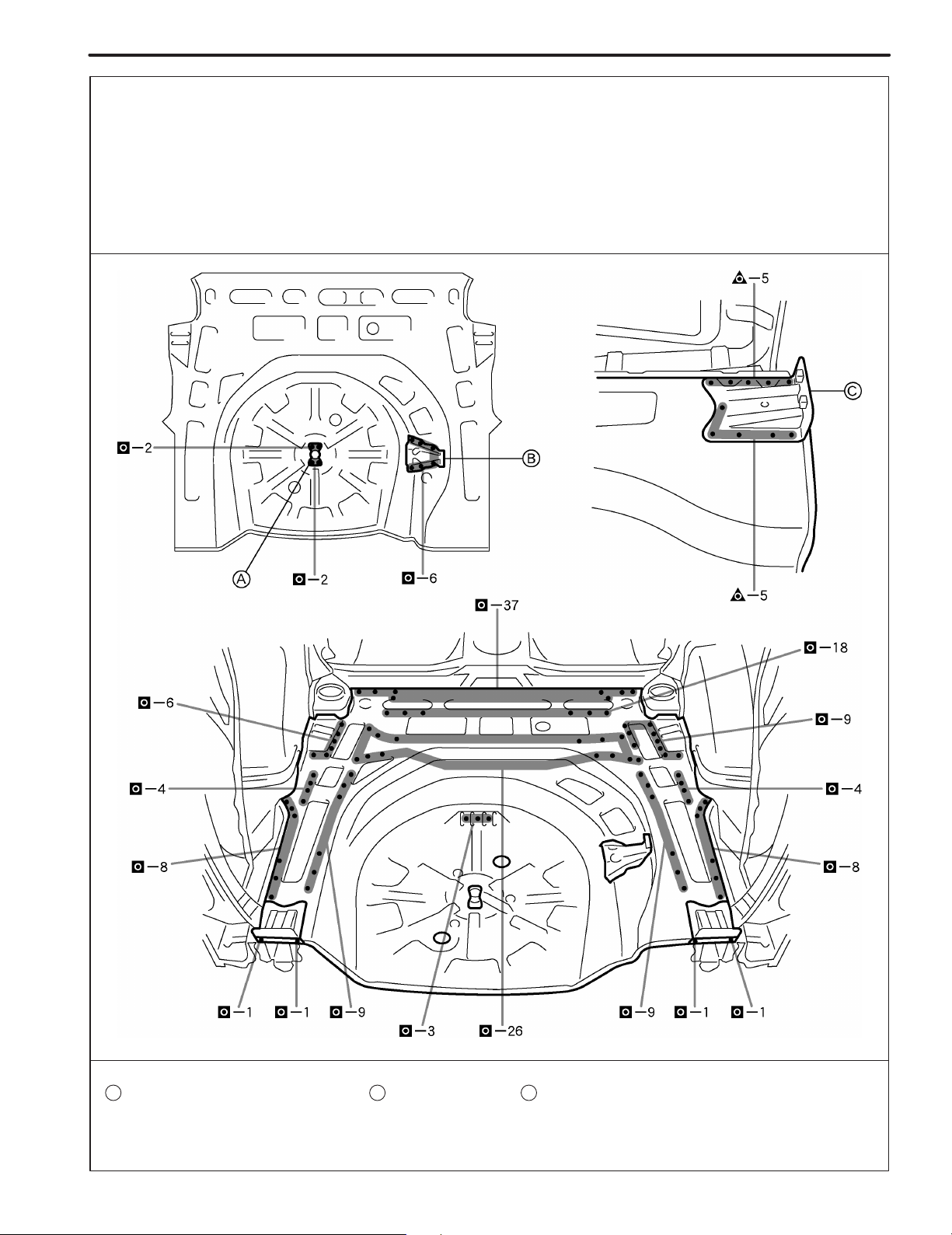
BODY PANEL REPLACEMENT
REAR FLOOR PAN (ASSY)
REMOVAL
With the body lower back panel, rear absorber No.1 bracket (sedan), rear floor
center crossmember (liftback, wagon) removed.
BP-83
F14436-A
F14436

BP-84
BODY PANEL REPLACEMENT
F14631
BODY PANEL REPLACEMENT
BP-85
INSTALLATION
! Temporarily install the new parts and measure each part of the new parts in accordance with the body dimension
diagram. (See the body dimension diagram)
! Inspect the fitting of the related parts around the new parts before welding. This affects the appearance of the
finish.
! After welding, apply the polyurethane foam to the corresponding parts.
! After welding, apply body sealer and under-coating to the corresponding parts.
! After applying the top coat layer, apply anti-rust agent to the inside of the necked section structural weld spots.
PART NAME
A B
Spare Wheel Clamp Bracket Jack Carrier
C
Rear Floor Pan Reinforcement
F14437

BP-86
BODY PANEL REPLACEMENT
F14438

BODY PANEL REPLACEMENT
REAR FLOOR PAN (CUT)
REMOVAL
With the body lower back panel removed.
BP-81
F14621-A
POINT
1 Cut the at the location shown below.
A
PART NAME
A B
Rear Floor Pan
Rear Floor No.3 Crossmember
20mm (0.79in.)
C
Rear Floor Side Rear Member
F14621

BP-82
BODY PANEL REPLACEMENT
INSTALLATION
! Temporarily install the new parts and measure each part of the new parts in accordance with the body dimension
diagram. (See the body dimension diagram)
! Inspect the fitting of the related parts around the new parts before welding. This affects the appearance of the
finish.
! After welding, apply the polyurethane foam to the corresponding parts.
! After welding, apply body sealer and under-coating to the corresponding parts.
! After applying the top coat layer, apply anti-rust agent to the inside of the necked section structural weld spots.
POINT
1 Cut the for the at the location as shown below.
1
2 !
D A
: Plug weld the overlapping portion of the .
D
HINT:
1) Be sure the portion to be welded are align and not loose.
3 Coat the overlapping opening portion from the both sides with body sealer.
PART NAME
A B
Rear Floor Pan
D
New Parts
G
Rear Floor Pan Reinforcement
E
Rear Floor No.3 Crossmember
Spare Wheel Clamp Bracket
F
C
Rear Floor Side Rear Member
Jack Carrier
F14622

BODY PANEL REPLACEMENT
REAR FLOOR CENTER CROSSMEMBER
(ASSY): Liftback, Wagon
REMOVAL
BP-77
F14434-A
F14434

BP-78
BODY PANEL REPLACEMENT
INSTALLATION
! Temporarily install the new parts and measure each part of the new parts in accordance with the body dimension
diagram. (See the body dimension diagram)
! Inspect the fitting of the related parts around the new parts before welding. This affects the appearance of the
finish.
! After welding, apply the polyurethane foam to the corresponding parts.
! After welding, apply body sealer and under-coating to the corresponding parts.
! After applying the top coat layer, apply anti-rust agent to the inside of the necked section structural weld spots.
PART NAME
A B
Rear Seat Back Hinge Mounting Bracket Rear Absorber Housing Bracket
20mm (0.79in.)
F14435

BODY PANEL REPLACEMENT
REAR ABSORBER MOUNTING NO.1
BRACKET (ASSY): Sedan
REMOVAL
BP-75
F14432-A
F14432

BP-76
BODY PANEL REPLACEMENT
INSTALLATION
! Temporarily install the new parts and measure each part of the new parts in accordance with the body dimension
diagram. (See the body dimension diagram)
! Inspect the fitting of the related parts around the new parts before welding. This affects the appearance of the
finish.
! After welding, apply the polyurethane foam to the corresponding parts.
! After welding, apply body sealer and under-coating to the corresponding parts.
! After applying the top coat layer, apply anti-rust agent to the inside of the necked section structural weld spots.
PART NAME
A
Rear Bumper Arm Bracket
F14433

BODY PANEL REPLACEMENT
BACK DOOR OPENING SIDE
REINFORCEMENT (ASSY): Liftback
REMOVAL
With the quarter panel, quarter panel end housing removed.
BP-73
F14428-A
50mm (1.97in.) 400mm (15.75in.)
F14428

BP-74
BODY PANEL REPLACEMENT
INSTALLATION
! Temporarily install the new parts and measure each part of the new parts in accordance with the body dimension
diagram. (See the body dimension diagram)
! Inspect the fitting of the related parts around the new parts before welding. This affects the appearance of the
finish.
! After welding, apply the polyurethane foam to the corresponding parts.
! After welding, apply body sealer and under-coating to the corresponding parts.
! After applying the top coat layer, apply anti-rust agent to the inside of the necked section structural weld spots.
PART NAME
A
Quarter Panel Rear Extension
B
Belt Anchor To Roof Side Inner Reinforcement
F14429

BODY PANEL REPLACEMENT
QUARTER PANEL END HOUSING (ASSY):
Sedan
REMOVAL
BP-67
F14424-A
F14424

BP-68
BODY PANEL REPLACEMENT
INSTALLATION
! Temporarily install the new parts and measure each part of the new parts in accordance with the body dimension
diagram. (See the body dimension diagram)
! Inspect the fitting of the related parts around the new parts before welding. This affects the appearance of the
finish.
! After welding, apply the polyurethane foam to the corresponding parts.
! After welding, apply body sealer and under-coating to the corresponding parts.
! After applying the top coat layer, apply anti-rust agent to the inside of the necked section structural weld spots.
10mm (0.39in.)
F14425

BODY PANEL REPLACEMENT
QUARTER PANEL END HOUSING (ASSY):
Liftback
REMOVAL
With the body lower back panel removed.
BP-69
F14430-A
F14430

BP-70
BODY PANEL REPLACEMENT
INSTALLATION
! Temporarily install the new parts and measure each part of the new parts in accordance with the body dimension
diagram. (See the body dimension diagram)
! Inspect the fitting of the related parts around the new parts before welding. This affects the appearance of the
finish.
! After welding, apply the polyurethane foam to the corresponding parts.
! After welding, apply body sealer and under-coating to the corresponding parts.
! After applying the top coat layer, apply anti-rust agent to the inside of the necked section structural weld spots.
PART NAME
A B
Back Door Opening Lower Reinforcement
C
Quarter Panel Rear Lower Extension
D
F14431
Roof Side Inner Lower Panel
Back Door Opening Trough

BODY PANEL REPLACEMENT
QUARTER PANEL END HOUSING (ASSY):
Wagon
REMOVAL
With the body lower back panel removed.
BP-71
F14426-A
POINT
1 Remove the at the same time.
PART NAME
A
Roof Side Inner Lower Panel
A
F14426

BP-72
BODY PANEL REPLACEMENT
INSTALLATION
! Temporarily install the new parts and measure each part of the new parts in accordance with the body dimension
diagram. (See the body dimension diagram)
! Inspect the fitting of the related parts around the new parts before welding. This affects the appearance of the
finish.
! After welding, apply the polyurethane foam to the corresponding parts.
! After welding, apply body sealer and under-coating to the corresponding parts.
! After applying the top coat layer, apply anti-rust agent to the inside of the necked section structural weld spots.
PART NAME
A
Roof Side Inner Lower Panel
F14427

BODY PANEL REPLACEMENT
BODY LOWER BACK PANEL (ASSY): Sedan,
Liftback
REMOVAL
BP-63
F14420-A
F14420

BP-64
BODY PANEL REPLACEMENT
INSTALLATION
! Temporarily install the new parts and measure each part of the new parts in accordance with the body dimension
diagram. (See the body dimension diagram)
! Inspect the fitting of the related parts around the new parts before welding. This affects the appearance of the
finish.
! After welding, apply the polyurethane foam to the corresponding parts.
! After welding, apply body sealer and under-coating to the corresponding parts.
! After applying the top coat layer, apply anti-rust agent to the inside of the necked section structural weld spots.
F14421

BODY PANEL REPLACEMENT
BODY LOWER BACK PANEL (ASSY): Wagon
REMOVAL
BP-65
F14422-A
F14422

BP-66
BODY PANEL REPLACEMENT
INSTALLATION
! Temporarily install the new parts and measure each part of the new parts in accordance with the body dimension
diagram. (See the body dimension diagram)
! Inspect the fitting of the related parts around the new parts before welding. This affects the appearance of the
finish.
! After welding, apply the polyurethane foam to the corresponding parts.
! After welding, apply body sealer and under-coating to the corresponding parts.
! After applying the top coat layer, apply anti-rust agent to the inside of the necked section structural weld spots.
F14423

BODY PANEL REPLACEMENT
QUARTER WHEEL HOUSING OUTER PANEL
(ASSY): Sedan
REMOVAL
With the quarter panel, No.1 lower outer rail removed.
BP-51
F14607-A
POINT
1 After removing the , remove the quarter wheel housing outer panel.
PART NAME
A B
Roof Side Outer Panel Rear Bumper Side Bracket
A
C
F14607
Rear Wheel Opening No.1 Bracket

BP-52
BODY PANEL REPLACEMENT
PART NAME
A B
Roof Side Outer Panel Rear Bumper Side Bracket
C
Rear Wheel Opening No.1 Bracket
F14608

BODY PANEL REPLACEMENT
BP-53
INSTALLATION
! Temporarily install the new parts and measure each part of the new parts in accordance with the body dimension
diagram. (See the body dimension diagram)
! Inspect the fitting of the related parts around the new parts before welding. This affects the appearance of the
finish.
! After welding, apply the polyurethane foam to the corresponding parts.
! After welding, apply body sealer and under-coating to the corresponding parts.
! After applying the top coat layer, apply anti-rust agent to the inside of the necked section structural weld spots.
POINT
1 Determine the position of the new parts by assembly marks of the inner and outer panels.
1
2 !
: The value is reference value.
PART NAME
A B
Roof Side Outer Panel
D
Rear Seat Back Stopper Bracket
Rear Bumper Side Bracket
C
Rear Wheel Opening No.1 Bracket
7mm (0.28in.) 10mm (0.39in.)
F14609

BP-54
BODY PANEL REPLACEMENT
POINT
1 Determine the position of the new parts by assembly marks of the inner and outer panels.
1
2 !
: The value is reference value.
PART NAME
A B
Roof Side Outer Panel
D
Rear Seat Back Stopper Bracket
Rear Bumper Side Bracket
C
Rear Wheel Opening No.1 Bracket
7mm (0.28in.) 10mm (0.39in.)
F14610

BODY PANEL REPLACEMENT
QUARTER WHEEL HOUSING OUTER PANEL
(ASSY): Liftback
REMOVAL
With the quarter panel, No.1 lower outer rail removed.
BP-55
F14611-A
POINT
1 After removing the , remove the quarter wheel housing outer panel.
PART NAME
A B
Roof Side Outer Panel
20mm (0.79in.)
A
Rear Bumper Side Bracket
C
F14611
Rear Wheel Opening No.1 Bracket

BP-56
BODY PANEL REPLACEMENT
PART NAME
A B
Roof Side Outer Panel Rear Bumper Side Bracket
20mm (0.79in.)
C
Rear Wheel Opening No.1 Bracket
F14612

BODY PANEL REPLACEMENT
BP-57
INSTALLATION
! Temporarily install the new parts and measure each part of the new parts in accordance with the body dimension
diagram. (See the body dimension diagram)
! Inspect the fitting of the related parts around the new parts before welding. This affects the appearance of the
finish.
! After welding, apply the polyurethane foam to the corresponding parts.
! After welding, apply body sealer and under-coating to the corresponding parts.
! After applying the top coat layer, apply anti-rust agent to the inside of the necked section structural weld spots.
POINT
1 Determine the position of the new parts by assembly marks of the inner and outer panels.
1
2 !
: The value is reference value.
PART NAME
A B
Roof Side Outer Panel
D
Rear Seat Back Stopper Bracket
Rear Bumper Side Bracket
C
Rear Wheel Opening No.1 Bracket
7mm (0.28in.) 10mm (0.39in.)
F14613

BP-58
BODY PANEL REPLACEMENT
POINT
1 Determine the position of the new parts by assembly marks of the inner and outer panels.
1
2 !
: The value is reference value.
PART NAME
A B
Roof Side Outer Panel
D
Rear Seat Back Stopper Bracket
Rear Bumper Side Bracket
C
Rear Wheel Opening No.1 Bracket
7mm (0.28in.) 10mm (0.39in.)
F14614

BODY PANEL REPLACEMENT
QUARTER WHEEL HOUSING OUTER PANEL
(ASSY): Wagon
REMOVAL
With the quarter panel, No.1 lower outer rail removed.
BP-59
F14615-A
POINT
1 After removing the and , remove the quarter wheel housing outer panel.
PART NAME
A B
Roof Side Outer Panel
Roof Side Inner Front Extension
D
50mm (1.97in.)
A D
Rear Bumper Side Bracket
C
Rear Wheel Opening No.1 Bracket
F14615

BP-60
BODY PANEL REPLACEMENT
PART NAME
A B
Roof Side Outer Panel
D
Roof Side Inner Front Extension
50mm (1.97in.)
Rear Bumper Side Bracket
C
Rear Wheel Opening No.1 Bracket
F14616

BODY PANEL REPLACEMENT
BP-61
INSTALLATION
! Temporarily install the new parts and measure each part of the new parts in accordance with the body dimension
diagram. (See the body dimension diagram)
! Inspect the fitting of the related parts around the new parts before welding. This affects the appearance of the
finish.
! After welding, apply the polyurethane foam to the corresponding parts.
! After welding, apply body sealer and under-coating to the corresponding parts.
! After applying the top coat layer, apply anti-rust agent to the inside of the necked section structural weld spots.
POINT
1 Determine the position of the new parts by assembly marks of the inner and outer panels.
1
2 !
: The value is reference value.
PART NAME
A B
Roof Side Outer Panel
D E
Roof Side Inner Front Extension
Rear Bumper Side Bracket
Rear Seat Back Stopper Bracket
C
Rear Wheel Opening No.1 Bracket
7mm (0.28in.) 10mm (0.39in.)
F14617

BP-62
BODY PANEL REPLACEMENT
POINT
1 Determine the position of the new parts by assembly marks of the inner and outer panels.
1
2 !
: The value is reference value.
PART NAME
A B
Roof Side Outer Panel
D E
Roof Side Inner Front Extension
Rear Bumper Side Bracket
Rear Seat Back Stopper Bracket
C
Rear Wheel Opening No.1 Bracket
7mm (0.28in.) 10mm (0.39in.)
F14618

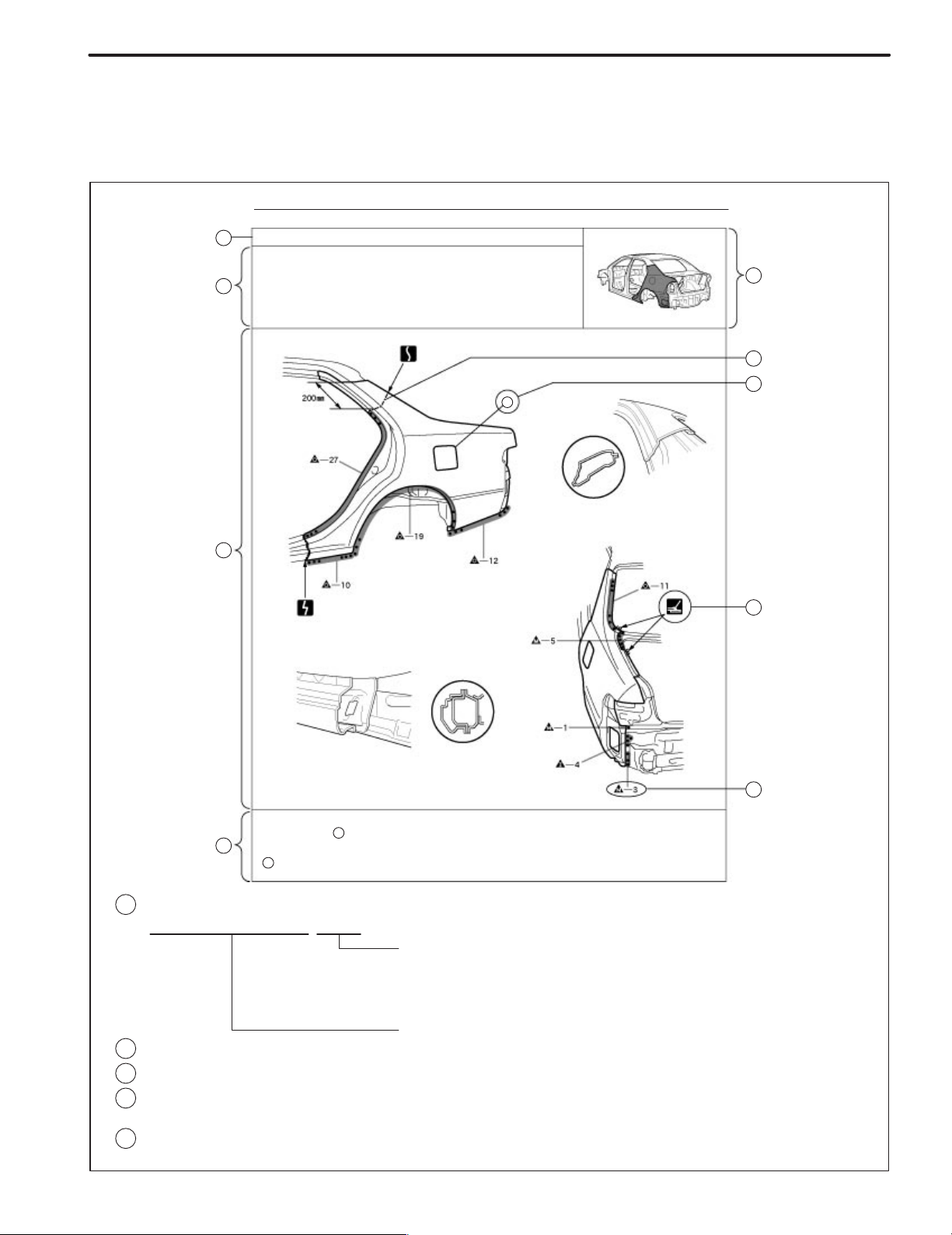
BP-42
BODY PANEL REPLACEMENT
QUARTER PANEL (CUT): Sedan
REMOVAL
F14500-A
POINT
1 Remove the at the same time.
B
PART NAME
A B
Fuel Filler Opening Lid
200mm (7.87in.)
F14500
Quarter Lock Pillar

BODY PANEL REPLACEMENT
BP-43
INSTALLATION
! Temporarily install the new parts and measure each part of the new parts in accordance with the body dimension
diagram. (See the body dimension diagram)
! Inspect the fitting of the related parts around the new parts before welding. This affects the appearance of the
finish.
! After welding, apply the polyurethane foam to the corresponding parts.
! After welding, apply body sealer and under-coating to the corresponding parts.
! After applying the top coat layer, apply anti-rust agent to the inside of the necked section structural weld spots.
F14624
POINT
1 Before initial spot welding the new parts, attach the quarter panel silencer sheet to the inside of the quarter
panel, at the position indicated on the diagram above.
HINT:
1) Use the quarter panel silencer sheet (Part No. 67813-44010).
PART NAME
A
Quarter Panel Silencer Sheet
58mm (2.28in.) 87mm (3.43in.)

BP-44
BODY PANEL REPLACEMENT
INSTALLATION
! Temporarily install the new parts and measure each part of the new parts in accordance with the body dimension
diagram. (See the body dimension diagram)
! Inspect the fitting of the related parts around the new parts before welding. This affects the appearance of the
finish.
! After welding, apply the polyurethane foam to the corresponding parts.
! After welding, apply body sealer and under-coating to the corresponding parts.
! After applying the top coat layer, apply anti-rust agent to the inside of the necked section structural weld spots.
POINT
1 Before temporarily installing the new parts, apply body sealer to the wheel arch.
HINT:
1) Apply body sealer about 5mm (0.20in.) from the flange, avoiding any oozing.
2) Apply sealer evenly, about 3 – 4mm (0.12 – 0.16in.) in diameter.
2 Use waterproof rivets for the installation.
A
HINT:
1) Apply the body sealer before installing the .
A
PART NAME
A
Fuel Filler Opening Lid
B
Quarter Lock Pillar
C
Waterproof Rivets
10mm (0.39in.)
F14602

BODY PANEL REPLACEMENT
QUARTER PANEL (CUT): Liftback
REMOVAL
BP-45
F14603-A
POINT
1 Remove the at the same time.
B
PART NAME
A B
Fuel Filler Opening Lid
150mm (5.91in.)
F14603
Quarter Lock Pillar
 Loading...