


Toshiba TLP-X2000U, TLP-X3000C, TLP-X3000U, TLP-X2500U, TLP-X3000B User Manual
...FILE NO. 330-200711GR
SERVICE MANUAL
3LCD DATA PROJECTOR
TLP-X2000E/B/U/C TLP-X2500E/B/U/C TLP-X3000E/B/U/C
The above models are classified as green product (s) (*1), as indicated by the underlined serial number (s).
This Service Manual describes replacement parts for green product (s). When repairing any green product (s), use the parts described in this manual and lead-free solder (*2).
For (*1) and (*2) , see the next page.
© TOSHIBA CORPORATION |
Published in Japan, July 2007 GREEN |

I
Table of Contents |
Contents |
|
|
|
|
Chapter 1 |
1-1 |
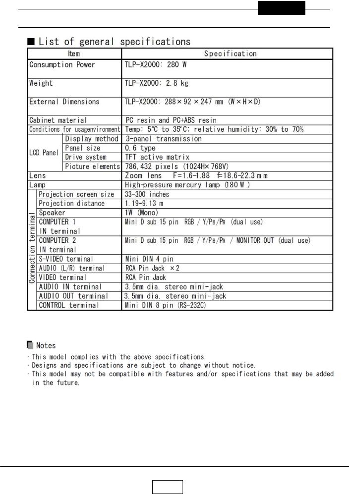
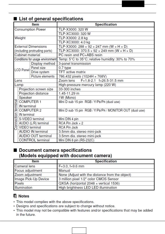
Specifications |
1-1 |
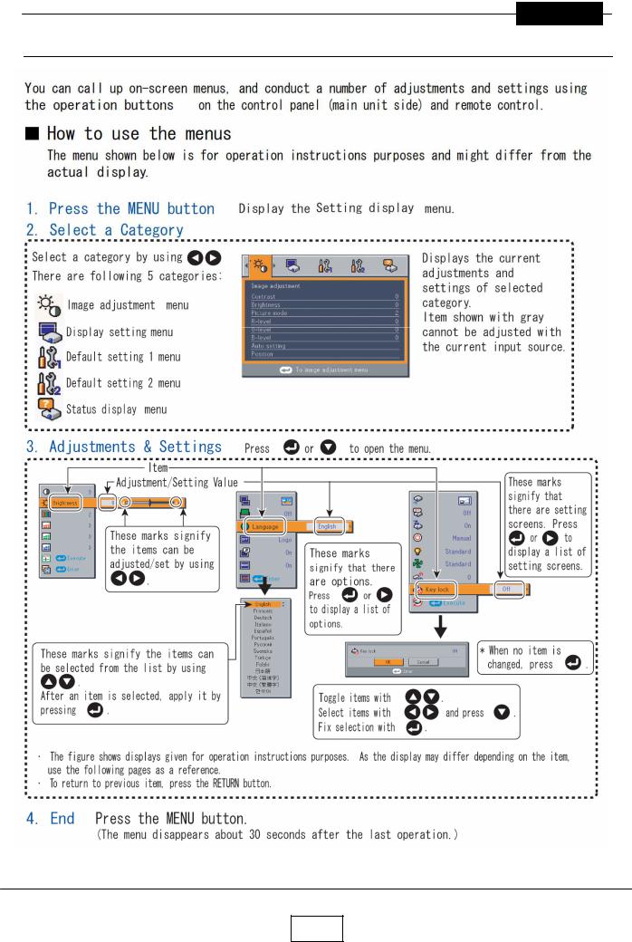
Using the Menus |
1-3 |
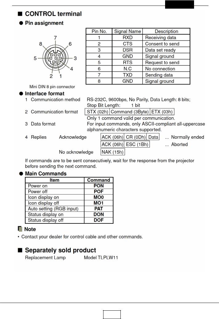
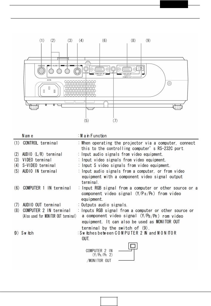
Names of the Terminals on the Rear Panel |
1-4 |
Name of each part on document camera |
1-5 |
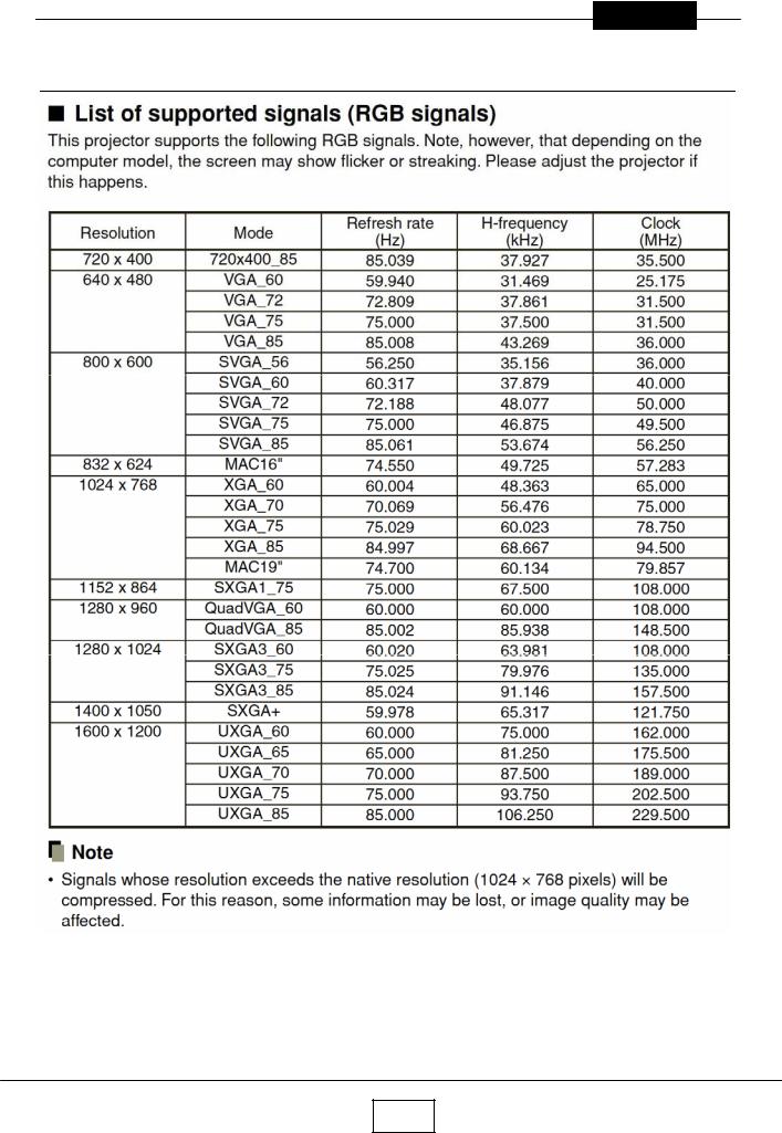
List of Supported Signals |
1-6 |
Chapter 2 |
2-1 |
Replaceable Part Hierarchy |
2-1 |
Required Tools |
2-2 |
Parts Replacement |
2-3 |
Replacement of optical parts |
2-15 |
Chapter 3 |
3-1 |
SINGOWS 2000 |
3-1 |
Chapter 4 |
4-1 |
Firmware Upgrade |
4-1 |
Chapter 5 |
5-1 |
Wiring Diagram |
5-1 |
Block Diagram |
5-2 |
Chapter 6 |
6-1 |
LED Display |
6-1 |
Troubleshooting |
6-2 |
Operation of Power Supply |
6-9 |
Chapter 7 |
7-1 |
Electrical adjustment |
7- 1 |
Chapter 8 |
8-1 |
Functional Test |
8-1 |
Chapter 9 |
9-1 |
Spare Parts List |
9-1 |
II
Chapter 1
Chapter 1
Specifications
1-1a

Chapter 1
Chapter 1
Specifications
1-1b
Chapter 1
Chapter 1
Specifications
1-1c
Chapter 1
1-2
Chapter 1
Using the Menus
1-3
Chapter 1
Names of the Terminals on the Rear Panel
1-4
Chapter 1
List of Supported Signals
1-5
Chapter 1
1-6
Chapter 2
Chapter 2
Replaceable Part Hierarchy
Replaceable Part Hierarchy
The flow chart below shows what parts must be removed to access each replaceable part in the projector.
The parts on the first level (Ex.Lamp cover) are accessible without removing any other parts.
The move levels down that a part is, the more parts you need to remove in order to access it.
Start |
|
|
|
|
|
|
|
|
|
|
|
|
|
|
|
|
|
|
|
|
|
|
|
|
|
|
|
|
|
|
|
|
|
|
|
|
|
|
|
|
|
|
|
|
|
Lamp |
|
|
Lamp |
|
Top cover |
|
|
PCB Main |
|
Cover for |
|
|
Power |
|
|
Front |
|
|
|
|
|
cover |
|
|
Bracket |
|
|
|
|
Power |
|
|
Main |
|
|
panel |
|
|
|
||
|
|
|
|
|
|
|
|
|
|
|
|
|
|
|
|
|
|||||
|
|
|
|
|
|
|
|
|
|
|
|
|
|
|
|
|
|
|
|
|
|
|
|
Control |
|
|
LED |
|
|
|
|
Remocon |
|
|
|
|
Optical |
|
|
LCD Fan |
|
|
Foot ADJ |
|
|
panel |
|
|
board |
|
|
|
|
receiver |
|
|
|
|
Engine |
|
|
|
|
||
|
|
|
|
|
|
|
|
|
|
|
|
|
|
|
|
|
|
||||
|
|
|
|
|
|
|
|
|
|
|
|
|
|
|
|
|
|
|
|
|
|
|
|
Lens cover |
|
|
Speaker |
|
|
|
|
PCB |
|
|
|
|
Intake |
|
|
Door SW |
|
|
PBS Fan |
|
|
|
|
|
|
|
|
Sensor |
|
|
|
|
Fan |
|
|
|
|
||||
|
|
|
|
|
|
|
|
|
|
|
|
|
|
|
|
|
|
|
|
||
|
|
|
|
|
|
|
|
|
|
|
|
|
|
|
|
|
|
|
|
|
|
|
|
|
|
|
|
|
|
|
|
|
|
|
|
|
|
|
|
|
|
|
|
|
|
Camera |
|
|
Camera |
|
|
|
|
|
|
|
|
|
Exhaust |
|
|
Balast & |
|
|
Balast |
|
|
assy |
|
|
Main |
|
|
|
|
|
|
|
|
|
Fan |
|
|
FAN assy |
|
|
Fan |
|
|
|
|
|
|
|
|
|
|
|
|
|
|
|
|
|
|
|
|
|
|
|
|
|
|
|
Camera |
|
|
|
|
|
|
|
|
|
Powe |
|
|
Lens |
|
|
Lamp |
|
|
|
|
|
KEY |
|
|
|
|
|
|
|
|
|
Filter Fan |
|
|
|
|
Driver |
|
|
|
|
|
|
|
|
|
|
|
|
|
|
|
|
|
|
|
|
|||
|
|
|
|
|
|
|
|
|
|
|
|
|
|
|
|
|
|
|
|
|
|
|
|
|
|
|
Camera |
|
|
|
|
|
|
|
|
|
|
|
|
Color |
|
|
Rear |
|
|
|
|
|
CMOS |
|
|
|
|
|
|
|
|
|
|
|
|
wheel |
|
|
panel |
|
|
|
|
|
|
|
|
|
|
|
|
|
|
|
|
|
|
|
|
|
|
|
|
|
|
|
Camera |
|
|
|
|
|
|
|
|
|
|
|
|
Power |
|
|
Thermal |
|
|
|
|
|
LED |
|
|
|
|
|
|
|
|
|
|
|
|
Filter |
|
|
SW |
|
|
|
|
|
|
|
|
|
|
|
|
|
|
|
|
|
|
|
|
|
|
|
|
|
|
|
|
|
|
|
|
|
|
|
|
|
|
|
|
|
|
|
|
|
|
|
|
|
|
|
|
|
|
|
|
|
|
|
|
|
|
LCD |
|
|
|
|
|
|
|
|
|
|
|
|
|
|
|
|
|
|
|
|
|
Panel |
|
|
|
|
|
|
|
|
|
|
|
|
|
|
|
|
|
|
|
|
|
|
|
|
|
|
|
|
|
|
|
|
|
|
|
|
|
|
|
|
|
|
|
|
|
|
|
|
|
|
|
|
|
|
|
|
|
|
|
|
|
|
|
|
|
LCD Filter |
|
|
|
|
|
|
|
|
|
|
|
|
|
|
|
|
|
|
|
|
|
|
|
|
|
|
|
|
|
|
|
|
|
|
|
|
|
|
|
|
|
|
|
|
|
|
|
2-1

Chapter 2
Required Tools
Item |
Photo |
Driver bit ( ) No 2
Box driver M3
Driver bit ( ) No 0
Torque driver bit ( ) No 2
Nippers
Cutting pliers
2-2
Chapter 2
Parts Replacement
1.Lamp
No |
Figure |
Explanation |
|
|
Remove two lamp cover screws. |
1
Remove three lamp screws.
Lamp is pulled out.
2
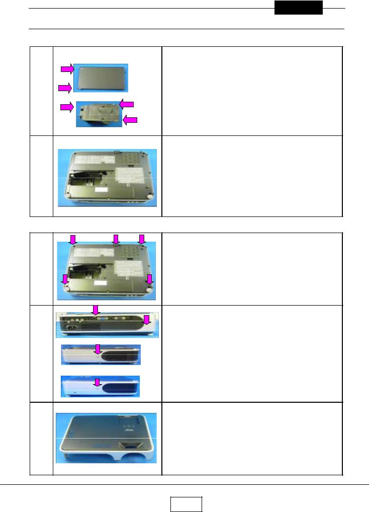
2.Top Cover
Remove five screws at the bottom.
Remove two screws at the rear.
Remove a screw at the right.
Remove a screw at the left.
Top cover is removed.
3
2-3
Chapter 2
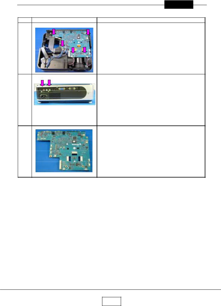
3.Main Board
Step |
Figure |
Explanation |
|
All the connectors on a main board unit are removed. |
1 |
Remove five screws. |
Remove two screws at the rear cover.
2
Main board is removed.
3
2-4

Chapter 2
4.Main Power Unit
Step |
Figure |
Explanation |
|
|
Remove four screws. |
1
|
Cover & Power Intake FAN are removed. |
2 |
Remove two screws. |
Power Intake FAN are removed.
3
Remove a screw.
4
Main Power Unit is taken out.
5
2-5
Chapter 2
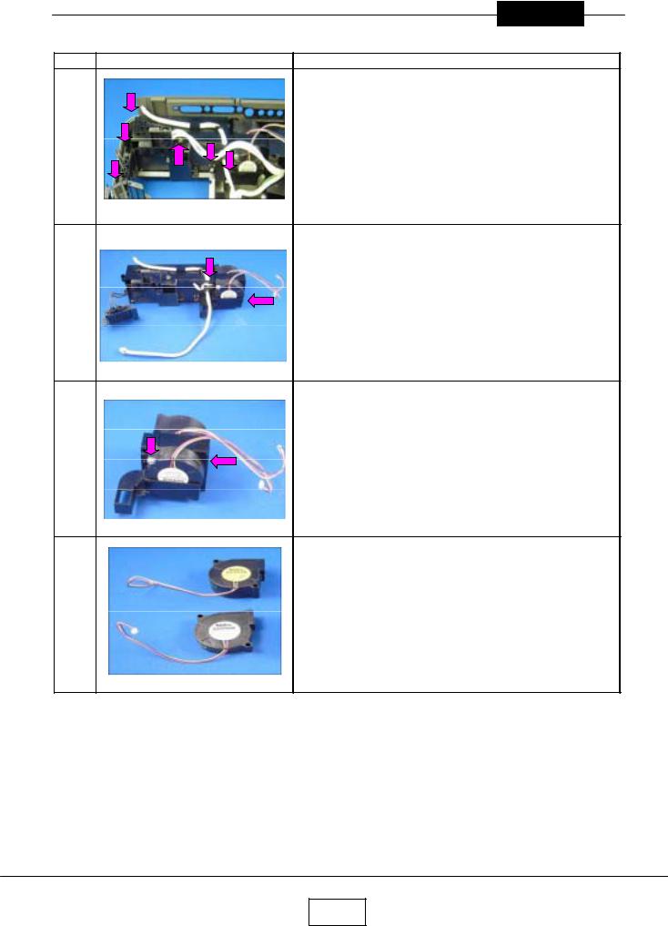
5.PBS & Ballast FANs
Step |
Figure |
Explanation |
Remove six screws.
1
Balast & FAN assy is taken out.
Remove two screws.
2
Remove two screws.
3
|
Ballast FANs are removed. |
4 |
PBS FANs are removed. |
2-6

Chapter 2
6.Exhaust Fan
1
2
Remove no screw.
Note.
May be very tight.
Exhaust Fan is removed.
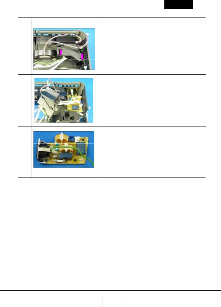
7.Ballast
1
2
Remove two screws.
Cover is removed.
Pinch a stud with cutting pliers. (4 points) Then pull up PC Board.
Ballast is removed.
3
2-7
Chapter 2
8.Filter Power
Step |
Figure |
Explanation |
Remove two screws.
1
Cover is removed.
2
Filter Power is taken out.
3
2-8
Chapter 2
9.Thermal Switch
Step |
Figure |
Explanation |
Remove a screws.
1
Remove two screws.
2
Cover is removed.
3
Thermal Switch is removed.
4
2-9
Chapter 2
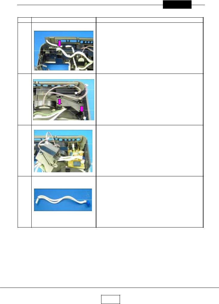
10.Optical Emgine
Step |
Figure |
Explanation |
Remove three screws.
1
Optical Engine is taken out.
2
11.Relay Board
Step |
Figure |
Explanation |
|
|
Remove three screws. |
1
Relay Board is removed.
2
2-10
Chapter 2
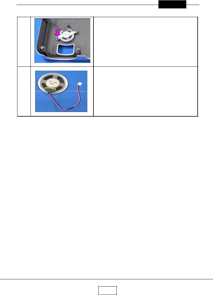
15.Speaker
Remove a screws.
1
Speaker is removed.
2
2-11

Chapter 2
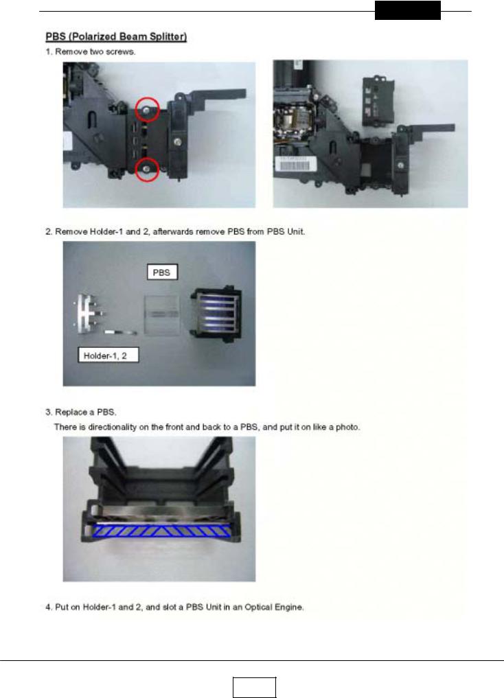
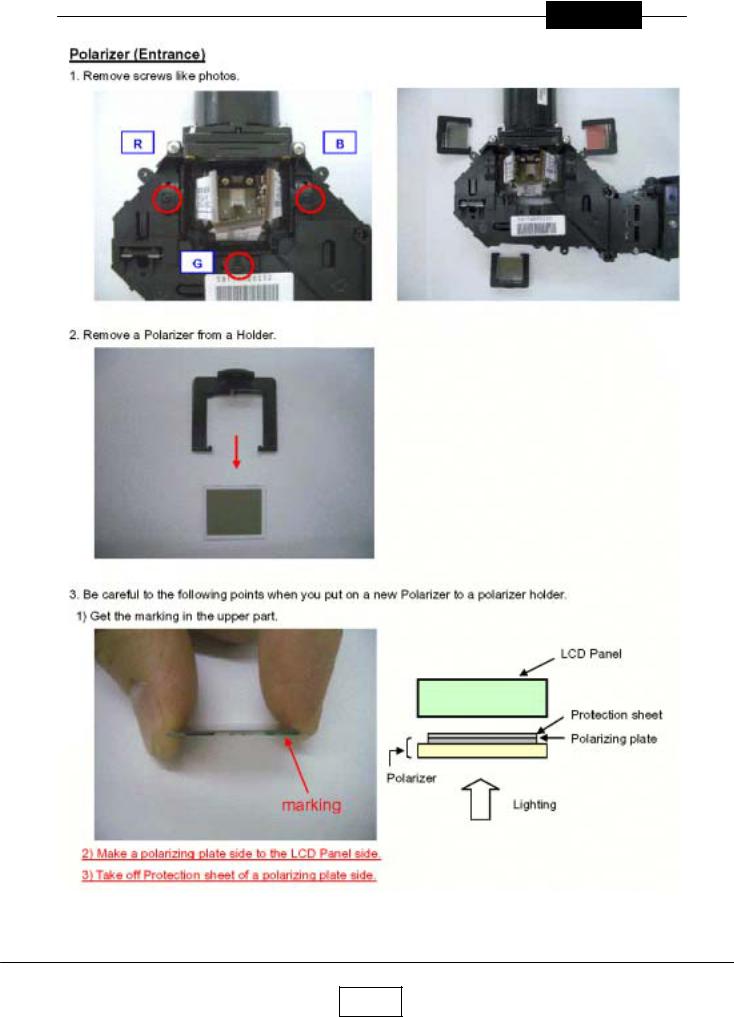
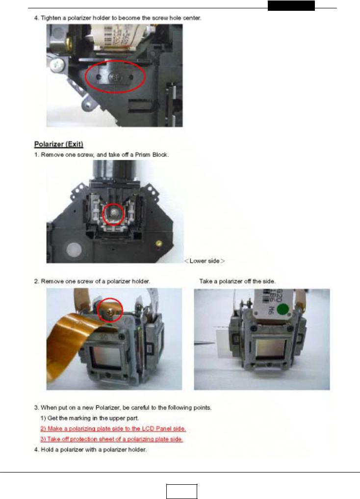
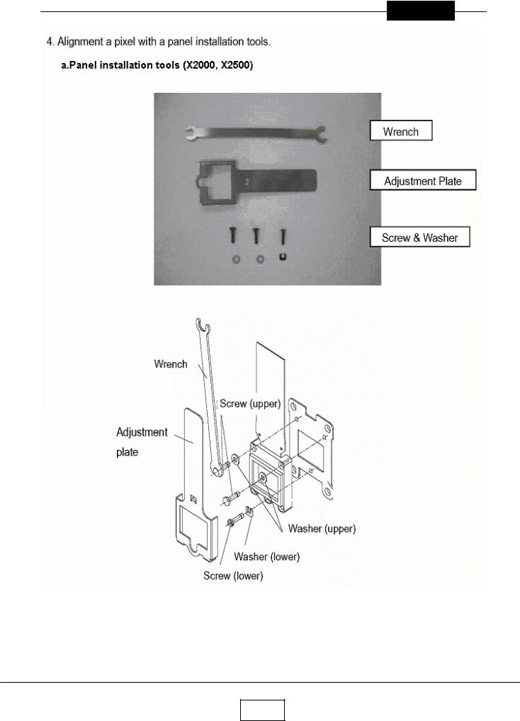
Replacement of Optical Parts
2-12
Chapter 2
2-13
Chapter 2
2-14
Chapter 2
2-15

Chapter 2
2-16
Chapter 2
2-17
 Loading...