

Toshiba Strata XII User Guide
TOSHIBA SYSTEM PRACTICES
, EL,ECTRONIC KEY TELEPHONE SYSTEM
I
GENERAL DESCRIPTION
SECTION 100-020-100
JUNE 1983
Strata
XII&XX
GENERAL DESCRIPTION
GENERAL DESCRIPTION
GENERAL DESCRIPTION
SECTION
100-020-100
JUNE 1983
PARAGRAPH
01
01
.oo
02
02.00
02.10
02.20
03
04
05
06
06.00
06.10
06.20
06.30
06.40
07
07.00
07.10
07.20
TABLE OF CONTENTS
SUBJECT
TABLE OF CONTENTS
GENERAL ...................................
Summary Description
PHYSICAL DESCRIPTIONS
Key Service Units
Electronic Key Telephones.
Direct Station Selection Console
ELECTRICAL CHARACTERISTICS
TABLE A (Electrical Characteristics)
FEATURES and SERVICES.
TABLE B (Standard Features)
TABLE C (Optional Features)
SYSTEM OPERATION
SYSTEM CONFIGURATION
Key Service Unit (MKSU)
Power Supply Assembly.
Station Equipment
Installation.
Maintenance
FEATURES and OPERATION
General ..................................
Standard Features
Optional Features
...............................
..........................
........................
....................... 1
.......................... 1
.......................
........................... 9
.......................
..........................
..............................
..........................
...........................
....................
................
..................
..............
................... 9
................... 9
.....................
.....................
......................
4
PAGE
i
1
1
1
6
8
8
8
11
11
14
14
15
15
15
15
15
18
FIGURE NO.
1
2
3
4
5
6
7
8
9
10
ILLUSTRATION LIST
TITLE
STRATA XII MKSU (Dimensions)
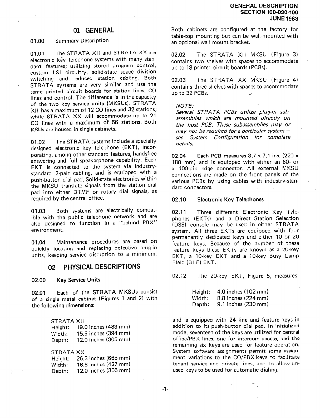
STRATA XX MKSU (Dimensions)
STRATA XII MKSU (Interior)
STRATA XX MKSU (Interior)
STANDARD 20-key EKT
OPTIONAL lo-key
DIRECT STATION SELECTION (DSS) CONSOLE
SYSTEM DIAGRAM
STRATA XII FUNCTIONAL BLOCK DIAGRAM
STRATA XX FUNCTIONAL BLOCK DIAGRAM.
EKT ..........................
.........................
............................
-I-
...................
...................
......................
......................
........
..........
.........
PAGE
.-
-_
2
3
4
5
6
7
7
10
12
13
GENERAL DESCRIPTION
SECTION 100-020-100
JUNE
1983
01 GENERAL
01.00
01.01
electronic key telephone systems with many standard features; utilizing stored program control,
custom LSI circuitry, solid-state space division
switching and reduced station cabling. Both
STRATA systems are very similar and use the
same printed circuit boards for station lines, CO
lines and control. The difference is in the capacity
of the two key service units (MKSUs). STRATA
XII has a maximum of 12 CO lines and 32 stations;
while STRATA XX will accommodate up to 21
CO lines with a maximum of 56 stations. Both
KSUs are housed in single cabinets.
01.02
designed electronic key telephone (EKT), incorporating, among other standard features, handsfree
answering and full speakerphone capability. Each
EKT is connected to the system via industrystandard 2-pair cabling, and is equipped with a
push-button dial pad. Solid-state electronics within
the MKSU translate signals from the station dial
pad into either DTMF or rotary dial signals, as
required by the central office.
Summary Description
The STRATA XII and STRATA XX are
The STRATA systems include a specially
Both cabinets are configured- at the factory for
table-top mounting but can be wall-mounted with
an optional wall mount ,bracket.
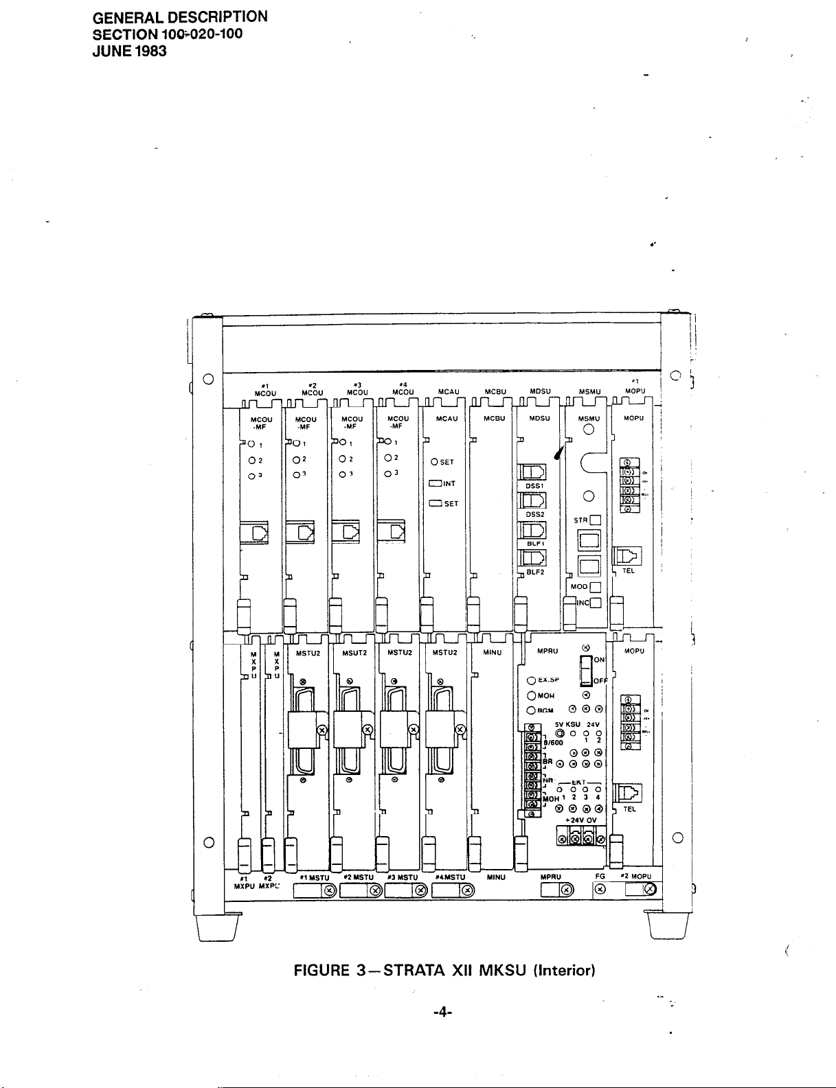
02.02 The STRATA XII MKSU (Figure 3)
contains two shelves with spaces to accommodate
up to 18 printed circuit boards (PCBs).
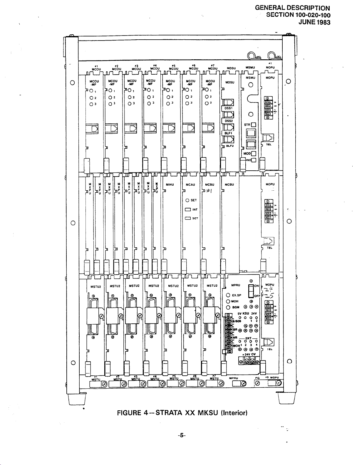
02.03 The STRATA XX M’KSU (Figure 4)
contains three shelves with spaces to accommodate
up to 32 PCBs. .-
NOTE:
Several STRATA PCBs utilize plug-in subassemblies which are mounted directly on
the host PCB. These subassemblies may or
may not be required for a particular system see System Configuration for complete
de tails.
02.04
180 mm) and is equipped with either an 80- or
a loo-pin edge connector. All external MKSU
connections are made on the front panels of the
various PCBs by using cables with industry-stan-
dard connectors.
02.10
Each PCB measures 8.7 x 7.1 ins. (220 x
Electronic Key Telephones
01.03
ible with the public telephone network and are
also designed to function in a “behind PBX”
environment.
01.04
quickly locating and replacing defective plug-in
units, keeping service disruption to a minimum.
Both systems are electrically compat-
Maintenance procedures are based on
02 PHYSICAL DESCRIPTIONS
02.00
02.01
of a single metal cabinet (Figures 1 and 2) with
the following dimensions:
Key Service Units
Each of the STRATA MKSUs consist
STRATA XII
Height:
Width:
Depth:
STRATA XX
Height:
Width:
Depth:
19.0 inches (483 mm)
15.5 inches (394 mm)
12.0 inches (305 mm)
26.3 inches (668 mm)
16.8 inches (427 mm)
12.0 inches (305 mm)
02.1 I
phones (EKTs) and a Direct Station Selection
(DSS) console may be used in either STRATA
system. All three EKTs are equipped with four
permanently dedicated keys and either 10 or 20
feature keys. Because of the number of these
feature keys these EKTs are known as a 20-key
EKT, a 1 O-key EKT and a 1 O-key Busy Lamp
Field (BLF) EKT.
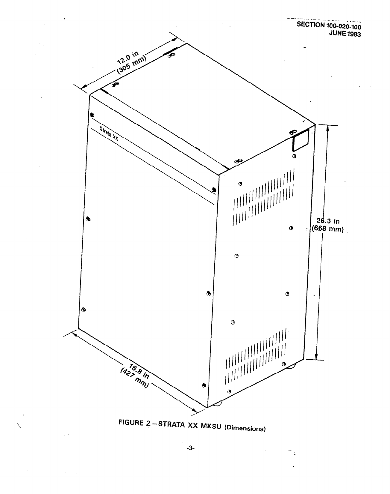
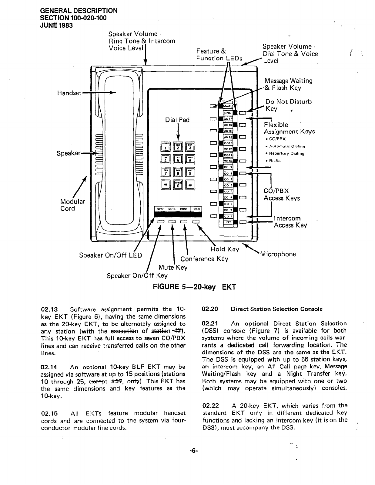
02.12
and is equipped with 24 line and feature keys in
addition to its push-button dial pad. In initialized
mode, seventeen of the keys are utilized for central
office/PBX lines, one for intercom access, and the
remaining six keys are used for feature operation.
System software assignments permit some assign-
ment variations to the CO/PBX keys to facilitate
tenant service and private lines, and to allow un-
used keys to be used for automatic dialing.
Three different Electronic Key Tele-
The 20-key EKT, Figure 5, measures:
Height:
Width:
Depth:
4.0 inches (102 mm)
8.8 inches (224 mm)
9.1 inches (230 mm)
-l-
.-
:

GENERAL DESCRIPTION
SECTION 100-020-100
JUNE 1983
FIGURE 1 -STRATA XII MKSU (Dimensions)
19.0
483
in
mm)
-2-
. .
:
--- --- -- -- - -
SECTION
------- -----
100-020-100
JUNE 1983
i8
3 in
mm)
FIGURE S-STRATA XX MKSU (Dimensions)
-3-
._
GENERAL DESCRIPTION
SECTION 100;020-100
JUNE 1983
4
PI
0
MOO”
-MF
01
02
03
4b”
MC*”
MCS”
MCS”
DSS2
STR!-J
MOP”
MOP”
*1
(I
. . .
;,,
I
1
El
El
SLF2
-
L
MlN”
I
ouou
OSGM
@@@
TEL
I
.-
MOP”
0
P
u.
is.
El
I
0
i
r2
-
#4MST”
L
YIN”
TEL
L
*2
MOPL
0
FIGURE 3-STRATA XII MKSU (Interior)
-4-
GENERAL DESCRIPTION
SECTION 100-020-100
JUNE 1983
0
.,
MOP”
MOW
El
TEL
3
c.
.ec.
7
P
9
0
PA
MCOU
-MF
01
02
03
zl
“3
&”
MCOU
-MF
01 01
02
0’
71
YCOL
yj,“p
02
0’
&U
ucou
-YF
01
0’
0’
El
f&J
ucou
-MF
01
02
0'
El
MOSU
MSMU
,O
0
STR
f-J
101
lol
MOOO
MII
g
Ii2
MlNU
0
-
MST”2
Q
$
d
Q
-
.
MWU2
~
I
FIGURE 4-STRATA XX MKSU
MSTU2
0
(Interior)
GENERAL DESCRIPTION
SECTION 100-020-100
JUNE 1983
Speaker Vc
Ring Tone
Voice Leve
Handset-
Ime
-
Intercom
Feature &
Function LEDs
Speaker Volume
Dial Tone &
Level
Message Waiting
H& Flash Key
Do Not Disturb
#Key . .
Voice
i . .
Speaker-
/
Modular
Cord
iker On/Off
SP
LgD
Mute-Key
Speaker On/Off Key
I
FIGURE
Dial Pad
Conference Key
5-20-key EKT
Flexible
Assignment Keys
l
COIPBX
l
Automatic Oiating
l
Repertory Dialing
l
Redial
_
1
CO/PBX
Access Kevs
-I
I ntercom
-Access Key
n
icrophone
02.13
key EKT (Figure 6), having the same dimensions
as the 20-key EKT, to be alternately assigned to
any station (with the e%ep&en
This lo-key EKT has full access to seven CO/PBX
lines and can receive transferred calls
lines.
02.14 An optional lo-key BLF EKT may be
assigned via software at up to 15 positions (stations
10 through 25, e-t #%?, only). This EKT has
the same dimensions and key features as the
1 O-key.
02.15
cords and are connected to the system via fourconductor modular line cords.
Software assignment permits the lo-
of s&3&n+?).
on
the other
All EKTs feature modular handset
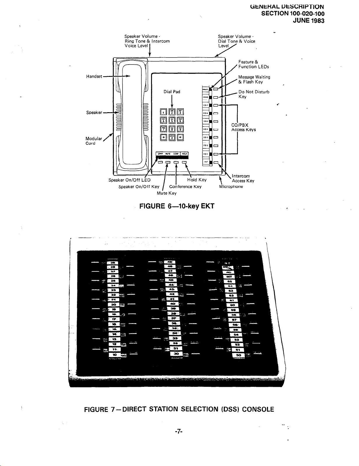
02.20
02.21
(DSS) console (Figure 7) is available for both
systems where the volume of incoming calls warrants a dedicated call forwarding location. The
dimensions of the DSS are the same as the EKT.
The DSS is equipped with up to 56 station keys,
an intercom key, an All Call page key, Message
Waiting/Flash key and a Night Transfer key.
Both systems may be equipped with one or two
(which may operate simultaneously) consoles.
02.22 A 20-key EKT, which varies from the
standard EKT only in different dedicated
functions and lacking an intercom key (it is on the
DSS), must accompany the DSS.
-6-
Direct Station Selection Console
An optional Direct Station Selection
key
Handset
Speaker Volume.
Ring Tone & Intercom
Voice Level
LitNtHAL UtSCRlPTlON
Feature &
Function LEDs
/
Message Waiting
/ & Flash Key
SECTION 100-020-100
JUNE 1983
Speaker
Modular
Cord
M;te Key
FIGURE
Dial Pad
Conference Key
6-lo-key
EKT
_ Do Not Disturb
Key
1
COIPBX
Access Keys
I
J
Intercom
Access Key
icrophone
4
FIGURE 7 -DIRECT STATION SELECTION (DSS) CONSOLE
-7-
.-
:
GENERAL DESCRIPTION
SECTION lot?-020400
JUNE 1983
One
02.23
be optionally added to either system as BLF
consoles. Their only function is to provide station
status information.
or two additional DSS consoles may
03 ELECTRICAL CHARACTERISTICS
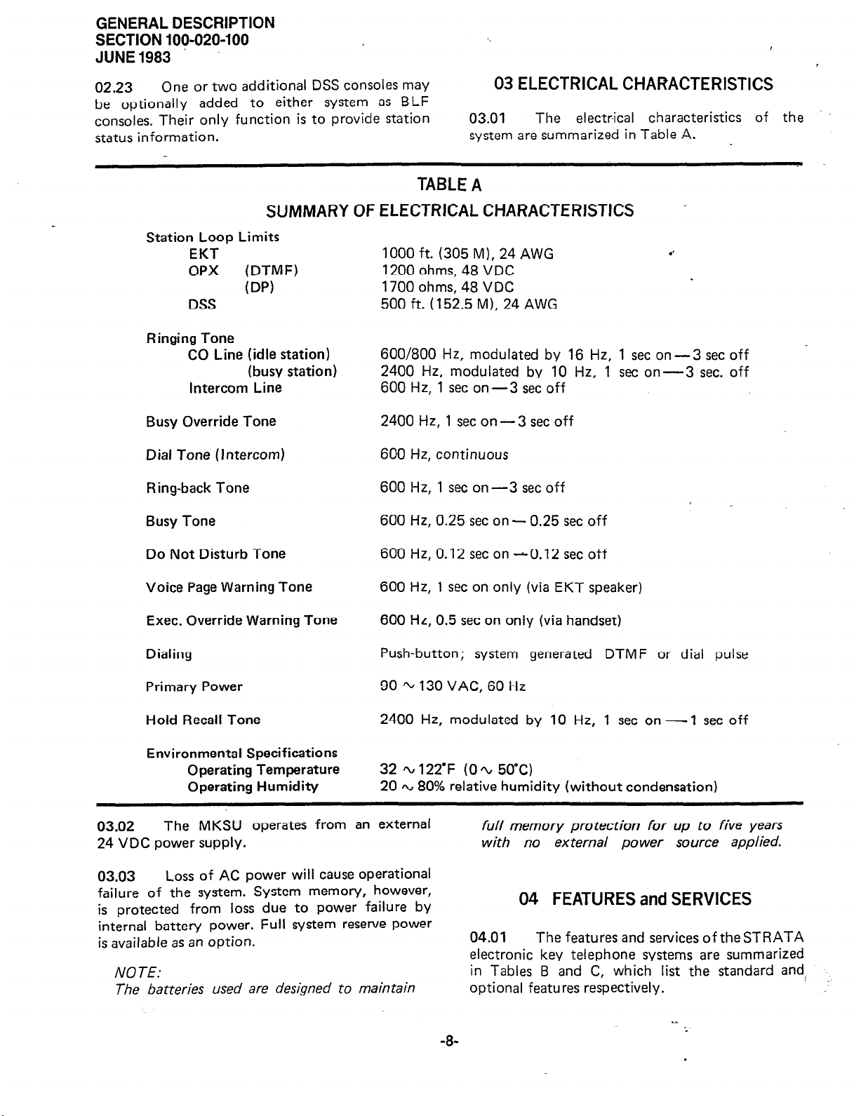
03.01
system are summarized in Table A.
The electrical characteristics of the
,
SUMMARY OF
Station Loop Limits
EKT
OPX
DSS
Ringing Tone
CO Line (idle station)
Intercom Line
Busy Override Tone
Dial Tone
Ring-back Tone
Busy Tone
Do Not Disturb Tone
Voice Page Warning Tone
(DTMF)
(DP)
(busy station)
(Intercom)
TABLE
A
ELECTRICAL CHARACTERISTICS -
1000 ft. (305 M), 24 AWG
1200 ohms, 48 VDC
1700 ohms, 48 VDC
500 ft. (152.5 M), 24 AWG
600/800 Hz, modulated by 16 Hz, 1 set on-3 set off
2400 Hz, modulated by 10 Hz, 1 set on-3 sec. off
600 Hz, 1 set on - 3 set off
2400 Hz, 1 set on-3 set off
600 Hz, continuous
600 Hz, 1 set on-3 set off
600 Hz, 0.25 set on - 0.25 set off
600 Hz, 0.12 set on - 0.12 set off
600 Hz, 1 set on only (via EKT speaker)
. .
Exec. Override Warning Tone
Dialing
Primary Power
Hold Recall Tone
Environmental Specifications
Operating Temperature
Operating Humidity
03.02
24 VDC power supply.
03.03
failure of the system. System memory, however,
is orotected from loss due to power failure by
internal battery power. Full system reserve Power
is available as an option.
NOTE:
The batteries used are designed to maintain
The MKSU operates from an external
Loss of AC power will cause operational
600 Hz, 0.5 set on only (via handset)
Push-button; system generated DTMF or dial pulse
90 ‘L 130 VAC, 60 Hz
2400 Hz, modulated by 10 Hz, 1 set on - 1 set off
32 ‘L 122-F (0% 5O’C)
20 Q 80% relative humidity (without condensation)
full memory protection for up to five years
with no external power source applied.
04 FEATURES and SERVICES
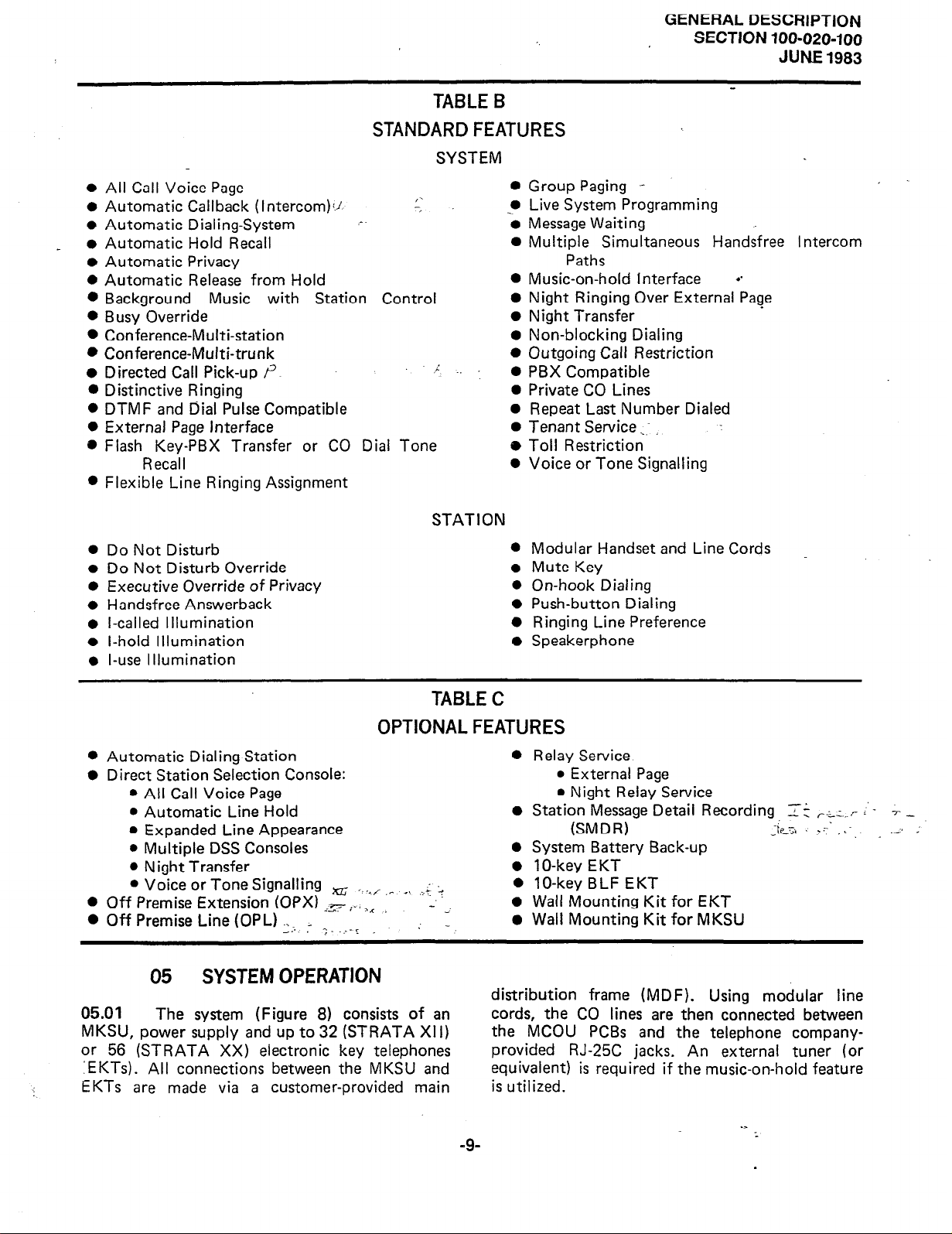
04.01
electronic key telephone systems are summarized
in Tables B and C, which list the standard and
optional features respectively.
The features and services of the STRATA
/
-8-
_ 0
STANDARD FEATURES
l
All Call Voice Page
0
Automatic Callback
0
Automatic Dialing-System -.
Automatic Hold Recall
0
Automatic Privacy
l
Automatic Release from Hold
0
Background Music with Station Control
0
Busy Override
0
Conference-Multi-station
l
Conference-Multi-trunk
0
Directed Call Pick-up r’
0
Distinctive Ringing
0
DTMF and Dial Pulse Compatible
0
External Page Interface
8
Flash Key-PBX Transfer or CO Dial Tone
Recall
0
Flexible Line Ringing Assignment
(Interc0m)i.l. I-Z
TABLE B
SYSTEM
.:
GENERAL
DESCRIPTION
SECTION 100-020-100
JUNE 1983
0
Group Paging --
Live System Programming
_*
Message Waiting
Multiple Simultaneous Handsfree Intercom
Paths
Music-on-hold Interface d
Night Ringing Over External Page
Night Transfer
Non-blocking Dialing
Outgoing Call Restriction
PBX Compatible
Private CO Lines
Repeat Last Number Dialed
Tenant Service ._:
Toll Restriction
Voice or Tone Signalling
0
Do Not Disturb
0
Do Not Disturb Override
0
Executive Override of Privacy
l
Handsfree Answerback
l-called Illumination
0
0
l-hold Illumination
l-use Illumination
0
l
Automatic Dialing-Station
0 Direct Station Selection Console:
l
All Call Voice Page
l
Automatic Line Hold
l
Expanded Line Appearance
l
Multiple DSS Consoles
l
Night Transfer
l
Voice or Tone Signalling xG ,;,./ ,L _I ._ ;’ G
l
Off Premise Extension (OPX) _= :., ,I
l
Off Premise Line(OPL) . . .
_ ‘_ .___r
_..
STATION
0
Modular Handset and Line Cords
Mute Key
a
0
On-hook Dialing
l
Push-button Dialing
0
Ringing Line Preference
Speakerphone
l
TABLE C
OPTIONAL FEATURES
0
Relay Service
0
Station Message Detail Recording Zt r-_z_. r >’
0
System Battery Back-up
0
1
0
lo-key BLF EKT
0
-. ._
; 0 _,
Wall Mounting Kit for EKT
Wall Mounting Kit for MKSU
l
External Page
l
Night Relay Service
(SMDR)
O-key EKT
Li<<t
: :< ..L
T _
-
05 SYSTEM OPERATION
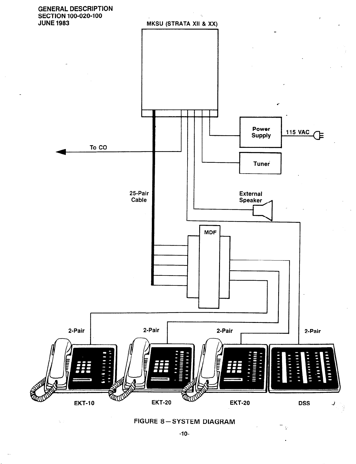
distribution frame (MDF). Using modular line
05.01 The system (Figure 8) consists of an
MKSU, power supply and up to 32 (STRATA Xl I)
or 56 (STRATA XX) electronic key telephones
: EKTs). All connections
‘,
EKTs are made via a
between the MKSU and
customer-provided main
cords, the CO lines are then connected between
the MCOU PCBs and the telephone companyprovided RJ-25C jacks. An external tuner (or
equivalent) is required if the music-on-hold feature
is utilized.
.>
-9-
GENERAL DESCRIPTION
SECTION 100-020-100
JUNE 1983
To CO
MKSU (STRATA Xl,“& XX)
-
t
-1 Tunei ]
25Pair
Cable
External
Speaker
/
MDF
r
P-Pair
FIGURE -8 -SYSTEM DIAGRAM
-IO-
._
DSS
J
:
ULlYCnn~
ucau-ut-
SECTION 100-020-100
JUNE
I IUI~
1983
t f
-
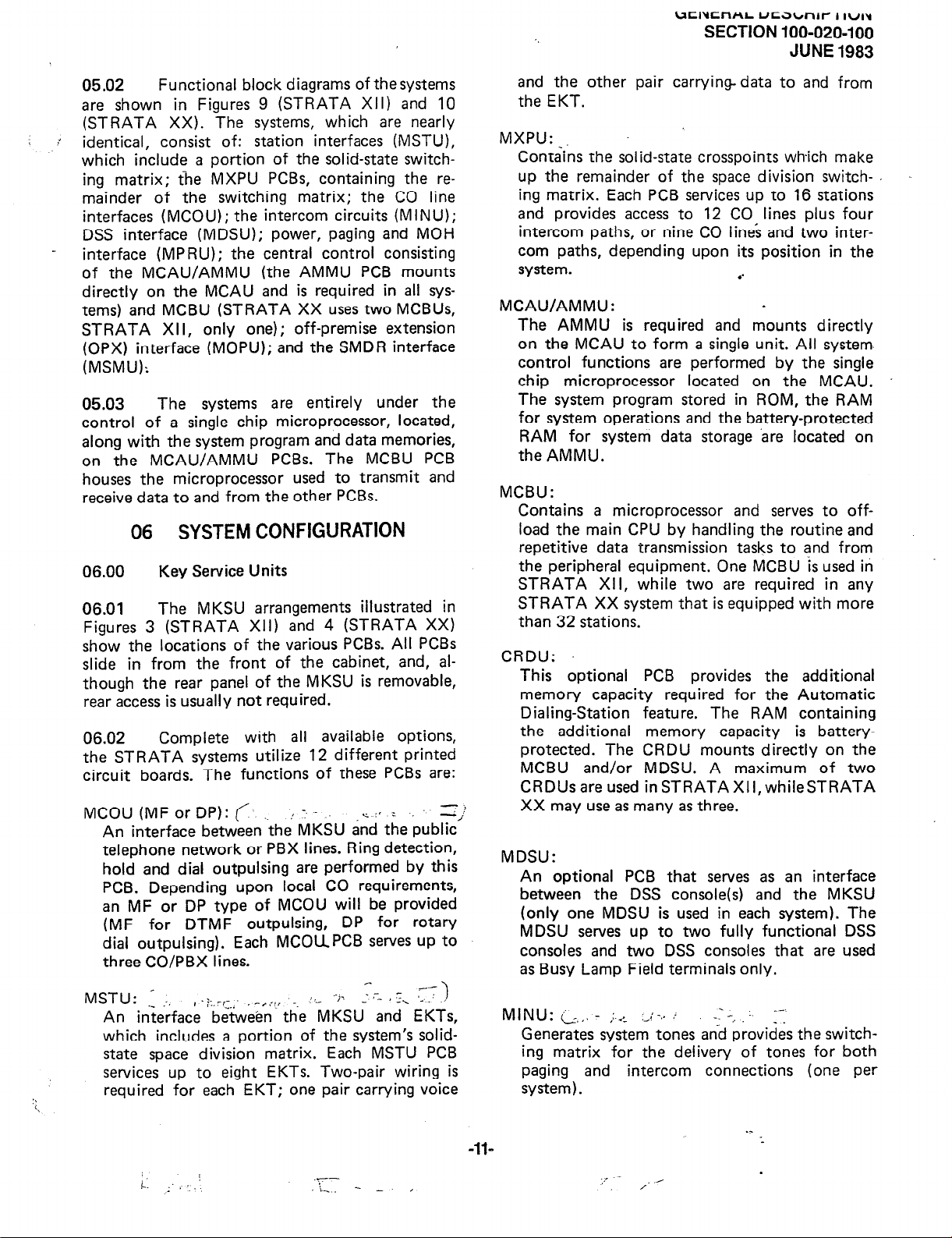
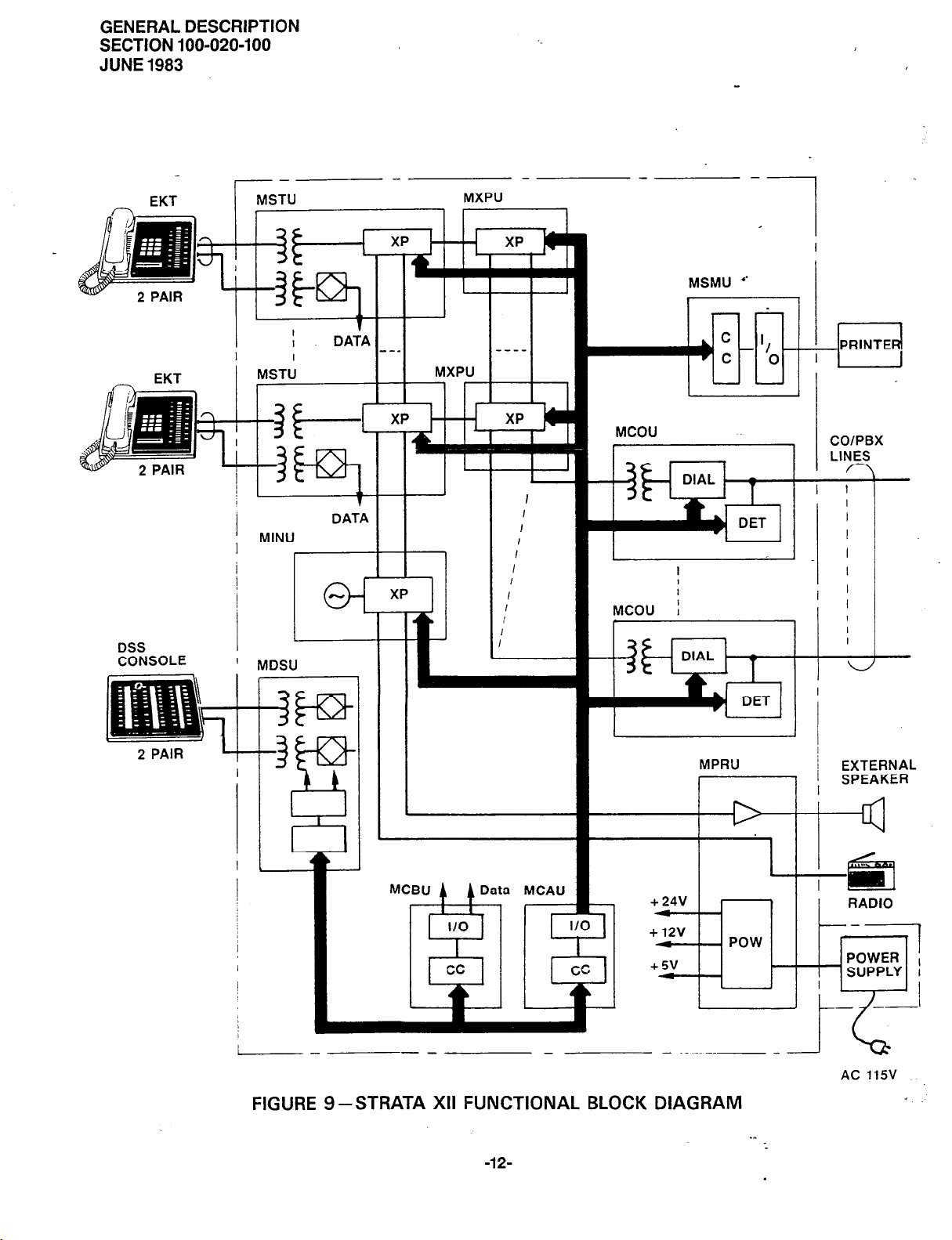
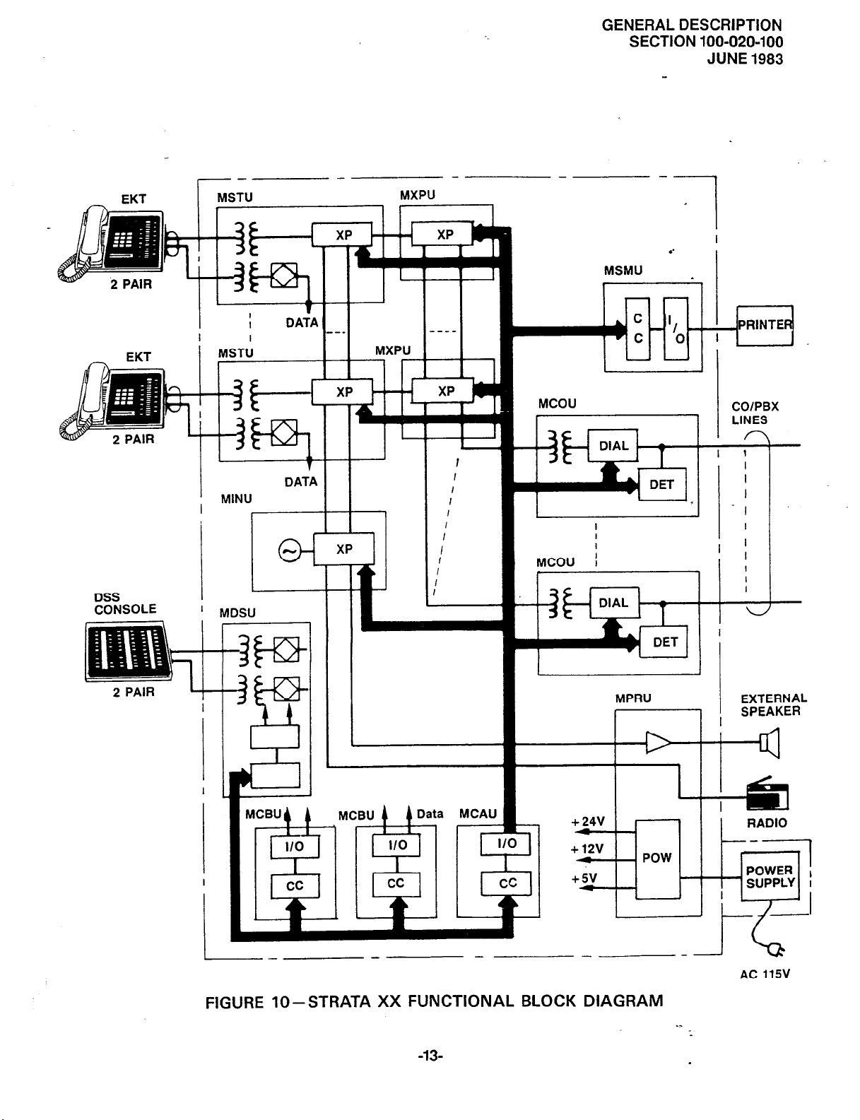
05.02 Functional block diagrams of the systems
are shown in Figures 9 (STRATA XII) and 10
(STRATA XX). The systems, which are nearly
identical, consist of: station interfaces (MSTU),
which include a portion of the solid-state switch-
ing matrix; the MXPU PCBs, containing the remainder of the switching matrix; the CO line
interfaces (MCOU); the intercom circuits (MINU);
DSS interface (MDSU); power, paging and MOH
interface (MPRU); the central control consisting
of the MCAU/AMMU (the AMMU PCB mounts
directly on the MCAU and is required in all systems) and MCBU (STRATA XX uses two MCBUs,
STRATA XII, only one); off-premise extension
(OPX) interface (MOPU); and the SMDR interface
(MSMU):
05.03
The systems are entirely under the
control of a single chip microprocessor, located,
along with the system program and data memories,
on the MCAU/AMMU PCBs. The MCBU PCB
houses the microprocessor used to transmit and
receive data to and from the other PCBs.
06.00
06.01
06 SYSTEM
Key Service Units
The MKSU arrangements illustrated in
CONFIGURATION
Figures 3 (STRATA XII) and 4 (STRATA XX)
show the locations of the various PCBs. All PCBs
slide in from the front of the cabinet, and, although the rear panel of the MKSU is removable,
rear access is usually not required.
06.02
Complete with all available options,
the STRATA systems utilize 12 different printed
circuit boards. The functions of these PCBs are:
MCOU(MForDP):(
. !-_-. .=:I= : 2)
An interface between the MKSU and the public
telephone network or PBX lines. Ring detection,
hold and dial outpulsing are performed by this
PCB. Depending upon local CO requirements,
an MF or DP type of MCOU will be provided
(MF for DTMF outpulsing, DP for rotary
dial outpulsing). Each MCOUPCB serves up to
three CO/PBX lines.
MSTU:
-
i:. rr-
‘;T ) _. ;_ , z, ,__: __
--
An interface‘ b&we%“th-e “-MKSU and EKTs,
which includes a portion of the system’s solidstate space division matrix. Each MSTU PCB
services up to eight EKTs. Two-pair wiring is
required for each EKT; one pair carrying voice
and the other pair carrying
data
to and from
the EKT.
MXPU:
Contains the solid-state crosspoints which make
up the remainder of the space division switch-
ing matrix. Each PCB services up to 16 stations
and provides access to 12 CO lines plus four
intercom paths, or nine CO lines and two intercom paths, depending upon its position in the
system.
MCAU/AMMU
:
l
.
The AMMU is required and mounts directly
on the MCAU to form a single unit. All system.
control functions are performed by the single
chip microprocessor located on the MCAU.
The system program stored in ROM, the RAM
for system operations and the battery-protected
RAM for system data storage are located on
the AMMU.
MCBU
:
Contains a microprocessor and serves to off-
load the main CPU by handling the routine and
repetitive data transmission tasks to and from
the peripheral equipment. One MCBU is used in
STRATA XII, while two are required in any
STRATA XX system that is equipped with more
than 32 stations.
CRDU:
This optional PCB provides the additional
memory capacity required for the Automatic
Dialing-Station feature. The RAM containing
the additional memory capacity is batteryprotected. The CRDU mounts directly on the
MCBU and/or MDSU. A maximum of two
CRDUsareused inSTRATAXII,whileSTRATA
XX may use as many as three.
MDSU:
An optional PCB that serves as an interface
between the DSS console(s) and the MKSU
(only one MDSU is used in each system). The
MDSU serves up to two fully functional DSS
consoles and two DSS consoles that are used
as Busy Lamp Field terminals only.
Ml NU
: L_, ,. - ,:..> ._; -., I.
-: -..
1;
Generates system tones and provides the switch-
ing matrix for the delivery of tones for both
paging and intercom connections (one per
system).
I
i: I _,!
.:
_y-
.\_. - - I
-ll-
GENERAL DESCRIPTION
SECTION 100-020-100
JUNE 1983
EKT
DSS
CONSOLE
1
MSTU
I
I
1
MINU
’ MDSU
MXPU
I
DATA
I
I
DATA
_-_
I I
____
I I
I
1
I
I
I
I
I
I
I
:
1
MCOU
L
MCOU ;
COIPBX
LINES
I 1
I
I
I
I
I
I
I
I
I
’
I
1
I
I
MPRU
11 ;
MCBU 4
1 Data MCAU
Tl
+ 24V
/
+ 12v
4
+5v
_
FIGURE g-STRATA XII FUNCTIONAL BLOCK DIAGRAM
-12-
POW
__
i EXTERNAL
SPEAKER
I
I
RADIO
-----I
POWER
SUPPLY I
AC 115V
’
:
GENERAL DESCRIPTION
SPEAKER
SECTION 100-020-100
JUNE 1983
5
MSMU _
I
l-l,_
e;ni
DSS
CONSOLE
XP
MXPU
IL.
I
I
I
XP -
I
I
I
I
I
I
I
.
c
MCOU
I-
I
>c
MPRU
COlPBX
1
LINES
EXTERNAL
MSTU
il
?
?5
) MINU, DATA 1 / ,
-1
MCBU( A
I_
MCBU 4 4 Data Mc*U 1
- -
1;7 zv ! 1-1 1 1 RADIO
FIGURE lo-STRATA XX FUNCTIONAL BLOCK DIAGRAM
-13-
-1
AC 115v
. .
GENERAL DESCRIPTION
SECTION 100-020-100
JUNE 1983
-_ s
r ‘!
il
, _.*.-;.- /
_:
MPRU - one per system:
Performs several system functions:
l
Provides connection points for the 24 VDC
input power.
l
Houses the voltage regulators that provide
12 VDC and 5 VDC for system operation.
l
Houses circuitry and connection points
for the relay services and music-on-hold
(MOH).
l
Houses the external page amplifier.
MOFVJ (DP or MF/DP): {L_- I ,,.“I
An optional PCB that serves as an interface
between the MKSU and conventional, single
line telephones or off-premise extension (OPX)
lines. Each MOPU PCB services two extensions.
A maximum of two MOPUs can be installed
‘2.
_ in STRATA XII and three in STRATA XX.
An MOPU DP will operate with rotary dialtype telephones only. Either DTMF or rotary
dial telephones can be used with an MOPU
MF/DP PCB.
MSMU/SCNU :
-IThe SCNU is required and mounts directly on
;:
;:i ‘,.
, _ .-
the MSMU to form a single unit. This optional
-PCB serves as an interface between the MKSU
_ and a printer or storage device used for the
SMDR feature. The PCB is equipped with an
RS 232C-type interface (one per ;syFem).
:)“iC i ,.
I -
MPLU/POPU (MF or DP):
The POPU is required and mounts directly on
the MPLU to form a single unit. This optional
PCB allows the bridging of a CO/PBX line
(which appears in the STRATA system) with
a conventional telephone. OP L telephones
thus connected will automatically cause a busy
indication within the STRATA system and
establish system privacy when initiating or
answering a call on the dedicated CO line. The
MPLU serves up to three CO/PBX line/OPL
combinations and replaces the MCOU that
would usually serve these lines. A maximum
of one MPLU may be used per system.
.< ,. .I;,- ;
- _
% inch toggle bolts or screws, The unit can accommodate “brown out” conditions or high voltages
within a range of 90 ‘Q
130
VAC, 60 Hz. A lo-ft.
AC power cord allows flexibility in lpcating the
power supply during installation.
06.12
An optional battery back-up unit (PBBU)
is available for the power supply. It is a printed
circuit board that mounts inside the power supply
housing and is connected to the recommended
battery pack (which is customer-supplied, consisting of two 12 VDC, maintenance-free, automobile
type batteries -
80 amp/hour maximum rating).
With the optional battery back-up assembly
installed, all functions of the STRATA systems will
continue to operate for several hours (the actua!
time period is in direct ratio to the type and size
of batteries selected) after a loss of normal electrical power. No calls will be disconnected during
switch-over to battery power.
06.20 Station Equipment
06.2 1 Standard electronic key telephone (EKT)
features include full speakerphone capability,
handsfree answerback and modular handset and
line
cords.
06.22 The principal components of the
STRATA 20-key EKT are: handset, dial pad,
speaker, ringing volume control, speakerphone
volume control, intercom key, 17 CO/PBX line
keys (or with up to seven Automatic Dialing keys)
and six feature keys. LED indicators are provided
for all keys except the HOLD, CONF and MUTE
keys.
06.23 In addition,
software options allow
complete compatibility of the STRATA VI EKT
with both of the STRATA XII & XX systems.
This lo-key EKT will have direct access to seven
CO/PBX lines, but can receive transferred calls
on all other unrestricted CO/PBX lines.
06.24
The optional lo-key BLF EKT may
be assigned via software at up to 15 positions
(stations 10 through 25, except #17, only). This
EKT has the same dimensions and key features as
the 1 O-key.
06.10
06.11
Power Supply Assembly
The separate power supply is a fixed unit
complete with a wall .mounting bracket.
ment to a wall or other fixed surface is
Attach-
via two
06.25 An optional Direct Station Selection
(DSS) console is available for both systems where
the volume of incoming calls warrants a dedicated
call forwarding location. The dimensions of th
DSS are the same as the EKT. The attendant _
-14-
GENERAL DESCRIPTION
SECTION
100-020-100
JUNE
1983
EKT varies from
ferent dedicated
intercom key (it
quipped with up to 56 station keys, an intercom
key, an All -Call page key, Message Waiting/Flash
key and a Night Transfer key. Either system may
be equipped with one or two fully functional
DSS consoles.
06.26
ally added to either system as BLF consoles. Their
only function
information.
06.27
different configurations of line and feature assignments are available. Some options include 17
CO/PBX
matic Dialing keys with a corresponding reduction
in available
06.28
of key assignments, which differ only in CO/
PBX line appearance.
06.30
06.31
the factory for table-top mounting, but the use
of the optional wall mount bracket and a simple
reversal of the back panel quickly converts them
for wall mounting.
One or two DSS consoles may be option-
Utilizing the 20-key EKT, thirteen
lines, while others offer up to seven Auto-
CO/PBX
The
Installation
The STRATA MKSUs are arranged at
the standard EKT only in dif-
key functions and lacking an
is on the DSS). The DSS is e-
is to provide station status
keys.
lo-key
EKT
offers five variations
External page output Night relay service
External page relay service
l
An RS 232C-type plug is provided on the
MSMU for connecting the SMDR printer;
l
OPX connections for two circuits are made
to the front of the MOPU PCB by using a single
2pair modular cord. External DC and ringing
power, is connected to the&lOPU via a screwterminal barrier strip.
l
OPL connections are made via 6-wire modular
cords to the front of the MPLU. Two cords are
required; one cord is connected to the CO jack
and serves up to three CO/PBX line connections as with an MCOU (the MPLU occupies
an MCOU PCB position), the second 6-wire
cord connects to the OPL jack and serves the
three OPL stations provided by that PCB.
06.33 The power supply is mounted to the
wall separately from the MKSU and connected
to the 24 VDC input on the MPRU PCB.
06.40
06.41 Faults in both STRATA systems are
repaired by replacing any faulty component (PCB,
subassembly, telephone, etc.) and returning it to
the manufacturer for repair.
Maintenance
06.32
via the faceplates of the various printed circuit
boards.
l
l
All connections to the MKSUs are made
CO/PBX line connections are made to the
front of each MCOU using one 3-pair modular cord for each card.
Each group of eight EKTs is connected to the
front of each MSTU with one standard 50-pin
amphenol-type connector.
DSS connections are made to the front of
the
MDSU PCB
for each DSS.
Screw-terminal barrier strips are mounted
on the front of the MPRU to provide attach-
ment points for the following connections:
24 VDC power input
Music-on-hold source input
with one 2-pair modular cord
07
07 .oo General
07.01 This section contains brief descriptions
of the STRATA features listed earlier in Tables B
and C and some associated operating instructions.
Detailed operating instructions can be found _in
the STRATA XII and XX USER GUIDE or
Section 100-020-400, operating
07.10
07.11
All Call Voice Page:
Dialing a 2-digit access code permits a station
user to page via all EKT speakers simultane
ously. The system can also be programmed to
include the External Page feature in an AH
Call Page.
-15-
FEATURES and OPERATION
Procedures.
Standard Features
System
GENERAL DESCRIPTION
SECTION 100-020-100
JUNE 1983
Automatic Callback (Intercom)
Permits a station user who encounters a busy
station on intercom to request a callback by
dialing a dedicated access code. The system then
monitors the called station and signals the caller
when it becomes idle.
Automatic Dialing-System:
This standard feature allows 24 numbers to be
stored in the system memory. After selecting
an outgoing line, any station user can cause
one of the stored numbers to be outpulsed
by dialing the proper access code.
Automatic Hold Recall:
A CO line placed on hold by any station will
recall that station after a programmable period
of time.
Automatic Privacy:
Privacy is automatic on all connections (except
OPL).
Automatic Release from Hold:
The system automatically releases held CO lines
if a disconnect signal is received from the
central office.
Background Music with Station Control:
Music from the music-on-hold source can, at
the station
speaker. The same music may also be broad-
cast via the external page interface if an external
speaker is installed.
Busy Override:
After dialing a
tone, the caller can dial a
burst to be sounded via the called EKT speaker.
Conference-Multi-station:
Conferencing is permitted to a maximum of
four stations and one CO or intercom line.
user’s
option, be heard via the EKT
busy station
:
and receiving a busy
q
and cause a tone
DTMF and Dial Pulse Compatible:
DTMF or rotary dial pulse signalling can be
sent to the CO/PBX line by installing the proper
MCOU PCB type.
External Page
Dialing a 2-digit code permits a station user
access to a customer-provided external speaker
via an internal 3-watt amplifier. As an option,
a 2-way, 600-ohm voice path is available for
use with a customer-supplies talk-back speaker/
amplifier.
Flash Key-PBX Transfer or CO Dial Tone Recall:
All EKTs are equipped with a Message Waiting/
Flash (MW/FL) key which, when operated while-
connected to a CO/PBX line, causes a timed
“flash” to be transmitted to the CO or PBX.
The timing of the flash can be programmed to
signal a PBX for feature operation or can be
long enough to cause a disconnect and dial
tone recall on a CO line. Also see Message
Waiting.
Flexible Line Ringing Assignment:
A programmable ring or no ring option is pro-
vided for each line selectively by each station.
Each line may be programmed to ring a maximum of eight stations.
Group Paging:
Special 2-digit access codes (81, 82, 83 or
84) permit voice paging to one of four zones.
Zone assignment is via software and is totally
flexible. Paging is via the EKT speakers.
Live System Programming:
Live system programming is accomplished
without service interruption to other station
users by placing the system in the special programming mode and inputting data via station
17. Station 17 is the only station that is “down”
during programming.
Interface:
.,
Conference-Multi-trunk:
Conferencing of two CO lines and three stations
is permitted.
Directed Call Pick-up:
Intercom calls can be answered from any station
by going off-hook, without siezing a line, and
dialing the number of the ringing station.
Distinctive Ringing:
CO line and intercom calls are distinguished by
different ringing tones.
Message Waiting:
The designated Message Center can indicate
a message is waiting for any station with the
Message Waiting LED of that station. The called
station cancels the LED by lifting the handset
and operating the MW/FL key. Also see Flash
Key.
Multiple Simultaneous Handsfree Intercom Paths:
Four intercom paths are available in a STRATA
XII system and up to six paths in a STRATA
-16-
GENERAL DESCRIPTION
SECTION
100-020-100
JUNE
1983
XX. All intercom lines are able to carry handsfree conversations simultaneously.
Music-on-hold Interface:
An interface is included for a customer-provided
music source. CO lines placed on hold will be
connected to this source. In addition, this music
may also be broadcast from EKT speakers
and external page when the background music
options are selected.
Night Ringing Over External Page:
As a programmable option, while the night
mode is active, a system-generated ring tone
will be transmitted via the external speaker
whenever any line rings (see Tenant Service).
Night Transfer:
On a programmable optional basis, the STRATA
systems can function with two or three ringing
patterns. If three patterns are selected, they
are designated Day, Day 2, and Night. If only
two patterns are selected, Day and Night designations are used. In both cases, the ringing
modes are selected with the lNrl key on either
DSS console or station 10 (see Tenant Service).
two tenants to be served from the same MKSU
with each tenant’s lines appearing in the correct
sequence. When Tenant Service is used, Night
Ringing Over External Page will apply to lines
assigned to Tenant #l only. Also, Night Transfer of Ringing for Tenant #1 and Tenant #2
lines will be independantly controlled by DSS
#1 (station 10) and DSS #2 (station
respectively.
Toll Restriction:
Selectively programmed on i per-station, perline basis, STRATA performs
by rejecting the numbers “0” and “1” as the
first or second digit and limiting the total
number of digits dialed to seven or eight.
Voice or Tone Signalling:
A programmable system feature that optionally
selects either tone ringing or voice page as the
primary method of intercom call signalling.
The calling station, however, may choose the
alternate method by dialing /J following the
station number.
07.12
Station
toll
9
restriction
1 l),
Non-blocking Dialing:
Dialing is permitted on INT and all CO lines
simultaneously.
Outgoing Call Restriction:
Any station can be selectively restricted frqm
originating calls on any or all CO lines. However,
the station may still receive calls on the restricted line(s).
PBX Compatible:
STRATA features,
automatic dialing,
operation.
Private CO Lines:
Restrictions may
system so selected
on selected station(s).
Repeat Last Number Dialed:
The last number dialed by each station is always
stored by the system and will be dialed automatically whenever the station user selects
an outgoing line and depresses the
Tenant Service:
Variable CO/PBX line key assignments allow
such as toll restriction and
compatible with PBX
are
programmed into the
be
line(s) will appear only
co
q
key.
Do Not Disturb:
This feature is activated and deactivated by
alternate depressions of the @ key. A
station calling a station that is in the DND mode
will receive a fast busy tone.
Do Not Disturb Override:
After reaching a DND station, that station may
be advised that a call is waiting by dialing
A tone signal will be heard at the DND station.
Executive Override of Privacy:
A station that is programmed for this feature
will override the automatic privacy feature and
is able to enter any existing conversation within
the system. A warning tone, however, is inserted
before the overriding station is actually connected. A maximum of two stations can be
programmed for executive override.
Handsfree Answerback:
All EKTs are equipped for handsfree answerback on voice-announced intercom calls as
a standard feature.
l-called Illumination:
A distinctive flash appears on the intercom
LED
at the EKT that is actually being called.
q
.
-17-

GENERAL DESCRIPTION
SECTION 100-020-100
JUNE 1983
l-hold Illumination:
The EKT user is shown a distinctive LED
flash to indicate a line actually placed on hold
at the EKT. All other stations see a normal
on-hold-flash.
l-use Illumination:
A distinctive flash rate shows the line presently
in use at a given EKT. Other stations see a
steadly illuminated LED for that line.
Modular Handset and Line Cords:
All EKTs are equipped with modular handset
and line cords.
Mute Key:
All EKTs have a II key that may be used to
cut off the microphone when the speakerphone
is in use, thereby permitting a private local con-
versation.
On-hook Dialing:
STRATA lets you dial your calls with the handset still on-hook. Call progress can be heard
via the telephone speaker; no need to pick up
the handset until your party answers.
Push-Button Dialing:
All STRATA EKTs are equipped with pushbutton dial pads.
Ringing Line Preference:
A line ringing at a station can be answered by
merely lifting the handset or depressing the
(=I key. The ringing line will be automati-
cally selected.
Speakerphone:
All EKTs are fully functional speakerphones.
07.20 Optional Features
Automatic Dialing-Station:
Adding CRDUs to the MCBU and/or MDSU
increases the STRATA automatic dialing capabilities from the standard 24 numbers in Automatic DialingSystem to a maximum of 40
telephone numbers
list and 40 numbers
list.
in the system directory
in each station’s directory
allow the attendant to voice-page via the
EKT speakers at all the stations in the
system simultaneously. If the External Page
has been included in the All Call -via system
option selection, the m key will operate
that as well.
Automatic Line Hold-each calling CO/PBX
b)
line is automatically placed on hold when
the DSS operator activates a station key.
Expanded Line Appearance-twenty CO/
cl
PBX line keys are available on the EKT
associated with the DSS console. The
intercom and -1 keys for that EKT
are located on the DSS console.
Multiple DSS Consoles-the STRATA XII
d)
and STRATA XX systems will each support
two
fully funtional DSS consoles (which
may operate simultaneously) as well as two
additional consoles functioning only as
Busy Lamp Field terminals.
Night Transfer-the lNTl key on the DSS
4
console(s) or station 10 controls the system
ringing patterns.
Voice or Tone Signalling-the DSS may be
f)
programmed for tone or voice signalling
preference independently of the remainder
of the system. As with all stations, the
operator can choose the alternate mode
by dialing
number.
Off Premise Extension (OPX)
Installing an optional MOPU (DP or MF/DP)
PCB, along with auxiliary power and ringing
supply, allows the system to interface with
conventional single line telephones or off pre-
mise circuits. The MOPU serves two extensions
and a maximum of two may be installed in
STRATA XII and three in STRATA XX.
Off Premise Line (OPL):
Installing an optional MPLU (MF or DP) in
place of an MCOU PCB allows the bridging
of a CO/PBX line (which appears in theSTRATA
system) with a conventional telephone. Max-
imum: one per system.
a !-?J following the station
:
Direct Station Selection
a) All Call Voice Page -a single dedicated
on the DSS console (labeled m
(DSS) Console:
)
key
will
Relay Service:
-18-
When the optional relays are equipped on the
MPRU PCB, the following
for external equipment:
signals are provided
GENERAL DESCRIPTION
‘,
SECTION 100-020-100
JUNE 1983
a) External Page--the relay is activated when-
ever the external page circuit is accessed.
A “make” contact is provided for control
of background music on external page.
This is- required only when an external
page amplifier is used.
b) Night Relay Service-relay will provide a
dry contact at the NR terminals on the
front of the MPRU PCB. A strap option on
the MPRU allows the NR relay to function
in one of two modes:
1) Answering Machine Control- if the
strap remains intact, the relay is operated continuously when the system is
in night service. This mode is intended
for indirect control of an answering
machine.
2) Night Bell Control -if the strap is cut,
the relay pulses at a 1-sec. on, 3-sec. off
rate whenever the system is in night
transfer mode and an incoming call is
ringing the system. This mode is intended to be used for indirect control
of an external night bell.
Station Message Detail Recording (SMDR):
Adding the optional MSMU PCB allows data to
be collected for each outgoing and incoming
CO line call. This data may be output to a
printer or recording device- via the RS232C
interface located on the MSMU.
System Battery Back-up:
An optional PCB can be installed in theSTRATA
power supply to provide automatic switching to
standby battery power. During *normal power
conditions the batteries are kept fully charged
by the power supply.
lo-key EKT:
The IO-key E KT may be assigned to any station
except #17. This EKT has full access to seven
CO/PBX lines and can receive transferred calls
on other lines.
lo-key BLF EKT:
The optional lo-key B LF EKT may be used
at up to 15 positions (stations 10 through 25,
except #17, only). The BLF will display the
status of stations 10 through 25.
Wall Mounting Kit for EKT:
The STRATA EKT is easily converted for wall
mounting with an optional handset hanger kit.
Wall Mounting Kit for MKSU:
The MKSU is shipped configured for table
mounting, but the use of the optional wall
mount bracket and a simple reversal of the back
panel quickly converts it for wail mounting.
5
’
-19-
TOSHIBA SYSTEM PRACTICES
ELECTRONIC KEY TELEPHONE SYSTEM
INSTALLATION
SECTION 100-020-200
JUNE 1983
SGrata
XII&xx
INSTALLATION
+’ -
TOSHIBA SYSTEM PRACTICES
ELECTRONIC KEY TELEPHONE SYSTEM
INSTALLATlbN
TABLE OF CONTENTS
INS IALLAI IUN
SECTION 100-020-200
JUNE 1983
PARAGRAPH
01
02
03
03.00
03.10
03.20
03.30
04
04.10
04.20
05
05.10
06
06.00
06.10
07
07.00
07.10
07.20
07.30
08
08.00
08.10
08.20
08.30
08.40
08.50
08.60
08.70
08.80
09
09.00
09.10
09.20
09.30
IO
10.10
10.20
10.30
11
11.00
11.10
11.20
17.30
II.40
12
12.00
12.10
12.20
12.30
12.40
12.50
12.60
12.70
12.80
12.90
SUBJECT
TABLEofCONTENTS
ILLUSTRATION LIST
GENERAL ......................................................................................................................
PACKING..
MKSU LOCATION REQUIREMENTS
Power Requirements
Ventilation Requirements.
Environmental Factors.
Cabling Considerations.
MKSU MOUNTING................................................._
Table Mounting the MKSU
Wall Mounting the MKSU
PRINTED CIRCUIT BOARDS.
MPRUPCBOptions
POWER CONNECTIONS
MPRU PCB installation
PowerConnection................................;
PCBINSTALLATION ....................................................
Memory Protection
TABLEA-CRDUPOSITIONS
PCB installation Sequence.
TABLEB-MXPUPOSITIONS
MSMU Installation.
MOPU Installation.
CABLECONNECTIONS ..................................................
System Cable Configuration
Main Distribution Frame Configuration.
Station Cable Connections
TABLE C-CROSS-CONNECT DATA (STRATA Xl I & XX).
Intercom Code Assignment.
TABLE D-CROSS-CONNECT DATA (STRATA XX).
CO Line Connection
DSS/BLF Connection.
OPX/Conventional Telephone Connection
Off Premise Line (OPL) Connection
Station Message Detail Recording (SMDR) Connection.
ELECTRONIC KEY TELEPHONE INFORMATION.
General ............................................................
EKTWallMounting ....................................................
ConvertingtheEKT ....................................................
EKTConnections .....................................................
SYSTEM POWER-UP INITIALIZE.
Clearing Automatic Dialing.
SMDR Real Time Clock Adjustment.
Program Listing.
SYSTEMTESTPROCEDURES
EKT Functional Check.
OPX/Conventional Telephone Functional Check.
OPL
Circuit Functional Check.
SMDR
MISCELLANEOUS EQUIPMENT CONNECTIONS.
Wiring Connections
Feature Functional Check.
Feature Check
Music-on-hold/Background Music Source.
Music-on-hold Volume Control
External Paging Connections.
Direct External Speaker Connection.
External Amplifier Connection.
Talkback Amplifier.
Background Music.
Volume Setting Sequence.
Night Relay Service.
...................................................
....................................................
..........................................
...................................................
...............................................
.
;
........................................
.................................................
...............................................
................................................
..............................................
......................................................................................................
.................................................
....................................................
..............................................
...............................................
..............................................
....................................................
....................................................
.........................................
......................................
...............................................
..........................
..............................................
..............................
...................................................
..................................................
.....................................
.........................................
............................
...............................
...........................................
..............................................
........................................
......................................................
..............................................
.................................................
................................
............................................
..........................................
.......................................................
................................
....................................................
.....................................
............................................
.............................................
........................................
............................................
...................................................
....................................................
...............................................
...................................................
_i-
....................
.......
.
.-
-_
PAGE
..i
ii
;
2
z
2
$
....
z
5
7”
7
7
8
8
9
10
12
12
13
13
....
_I3
4
15
15
17
18
18
18
19
20
22
22
23
23
24
25
25
25
26
27
28
28
28
30
30
31
32
32
32
32
32
32
32
33
33
33
33
33
TOSHIBA SYSTEM PRACTICES
ELECTRONIC KEY TELEPHONE SYSTEM
INSTALLATlON
ILLUSTRATION LIST
IN3 IHLLAI IUN
SECTION 100-020-200
JUNE 1983
FIGURE
1
2
3
4
5
6
7
8
9
10
11
12
13
14
15
16
17
18
19
20
21
22
23
24
25
26
27
28
29
30
31
32
33
34
35
36
37
38
39
40
41
42
43
44
45
46
47
SUBJECT
CRDUBATTERYSTRAP..
AMMUBArrERYSTRAP
MSMUBATTERYSTRAP
MKSU WALL MOUNTING KIT TEMPLATE.
ASSEMBLED MKSU WALL MOUNTING KIT
MKSU..........................................................,
MKSU
MKSU
..........................................................................................................................
MPRURELAYSOCKETS&SWITCH
RELAYlNSTALLEDWlTHSW2SWlTCH
POWER SUPPLY-TO-MKSU WIRING.
AMMUONTOMCAU
CRDUONMCBU.................................................~
CRDUONMDSU
PCBs IN MKSU (STRATA XII)
PCBs IN MKSU (STRATA XX)
MSMUCONNECTIONSTRAPS
MSMU/RS232CCONNECTOR
MOPUCONNECTIONSTRAPS
SYSTEMDIAGRAM
MKSU CABLE CLAMPING.
MKSUCABLEROUTING
MDF/EKTWlRING
RJ25CWlRlNG
MKSUTOPCOVERREMOVAL
MKSUUPPERCABLEROUTING
MDSUWIRING
MOPUWIRING ......................................................
MPLUWIRING
MSMU-TO-PRINTER CABLING
20-key EKT
lo-keyEKT
REMOVING EKTBASE
EKTWIREACCESS
EKT WIRE ROUTING.
HANDSETHANGER KIT..
AMMUBATTERYSTRAP
SYSTEM INITIALIZING (STRATA XII).
SYSTEM INITIALIZING (STRATA XX).
MSMU FACEPLATE
SMDR PRINTOUT EXAMPLE (OUTGOING CALL RECORD).
SMDR PRINTOUT EXAMPLE (INCOMING CALL RECORD)
MPRU CONNECTION STRIP
IMPEDANCE SWITCH ON MPRU
EXTERNAL AMPLIFIER HOOK-UP
VOLUME SETTING CONTROLS
NRCONTACTS
.....................................................
...................................................
....................................................
......................................................
......................................................
.......................................................
.........................................................
.........................................................
...................................................
...................................................
......................................................
........................................
...............................................
...............................................
..............................
..................................
........................................
....................................
.......................................
..................................................
............................................
............................................
............................................
............................................
............................................
...............................................
...............................................
...........................................
..........................................
...........................................
.................................................
.................................................
.............................................
...............................................
.....................................
.....................................
.............................................
..........................................
........................................
...........................................
.......................
.......................
.._
.
....
...
...
PAGE
..
1
1
2
3
3
4
;
6
7
7
9
9
9
10
11
12
13
13
14
-15
15
16
19
19
19
20
21
22
23
23
24
24
24
25
25
25
26
26
28
31
31
32
32
33
34
35
01 GENERAL
INSTALLATION
SECTION 100-020-200
JUNE 1983
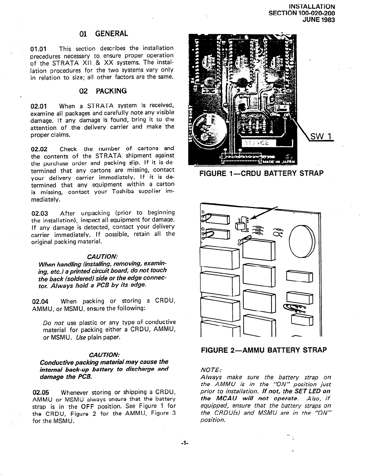
01.01
precedures necessary to ensure proper operation
of the STRATA XII & XX systems. The installation procedures for the two systems vary only
in relation to size; all other factors are the same.
This section describes the installation
02 PACKING
02.01
examine all packages and carefully
damage. If any damage is found, bring it to the
attention of the delivery carrier and make the
proper claims.
02.02
the contents of the STRATA shipment against
the purchase order and packing slip. If it is determined that any cartons are missing, contact
your delivery carrier immediately. If it is determined that any equipment within a carton
is missing,
mediately.
02.03
the installation), inspect all equipment
If any damage is detected, contact your delivery
carrier immediately. If possible, retain all the
original packing material.
When a STRATA system is received,
note any
Check the number of cartons and
contact your Toshiba supplier im-
After unpacking (prior to beginning
visible
for damage.
FIGURE l-CRDU BATTERY STRAP
CAUTION:
When handling (ins taking, removing, examin-
ing, etc.) a printed circuit board, do not touch
the back (soldered) side or the edge connector. Always hold a PCB by its edge.
02.04
AMMU, or MSMU, ensure the following:
Conductive packing material may cause the
internal back-up battery to discharge and
damage the PCB.
02.05 Whenever storing or shipping a CRDU,
AMMU or MSMU always ensure that the battery
strap is in the OFF position. See Figure 1 for
the CRDU, Figure 2 for the AMMU, Figure 3
for the MSMU.
When packing or storing a CRDU,
Do not use plastic or any type of conductive
material for packing either a CRDU, AMMU,
or
MSMU. Use plain paper.
CAUTION:
FIGURE 2-AMMU BATTERY STRAP
NOTE:
Always make sure the battery strap on
the AMMU is in the ‘ON” position just
prior to installation. If not, the SET LED on
the
MCA
U
will not operate.
equipped, ensure that the battery straps on
the CRDUls) and MSMlJ are in the “‘ON”
position.
Also, if
-l-
INSTALLATION
SECTION 100-020-200
JUNE 1983
FIGURE 3-MSMU BATTERY STRAP
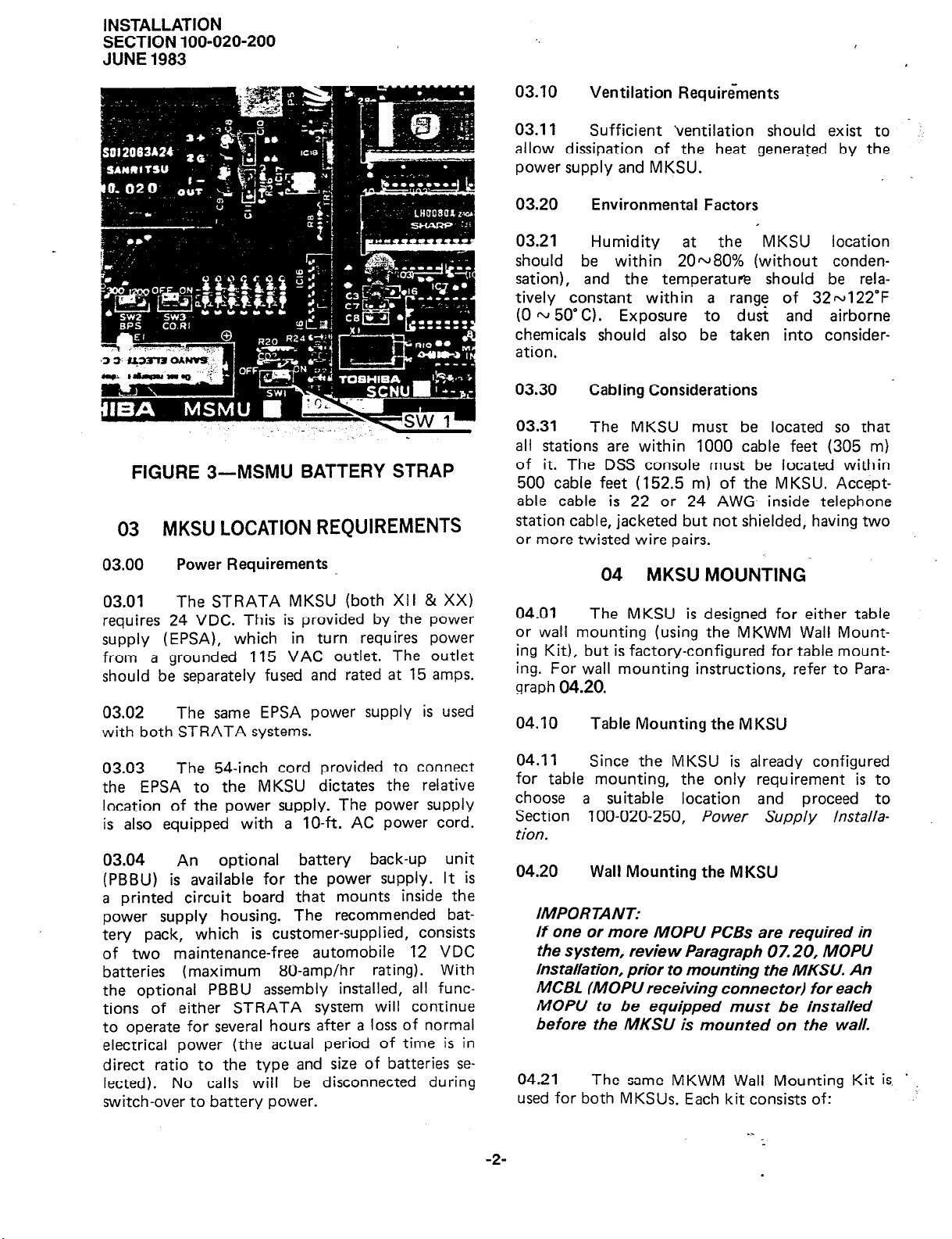
03 MKSU LOCATION REQUIREMENTS
03.00
03.01
requires 24 VDC. This is provided by the power
supply (EPSA), which in turn requires power
from a grounded 115 VAC outlet. The outlet
should be separately fused and rated at 15 amps.
03.02
with both STRATA systems.
Power Requirements
The STRATA MKSU (both XII & XX)
The same EPSA power supply is used
03.10
03.11
allow dissipation of the heat generated by the
power supply and MKSU.
03.20
03.21
should be within 20~80% (without condensation), and the temperature should be rela-
tively constant within a range of 32~122’F
(0 w 5o’C). Exposure
chemicals should also be taken into consideration.
03.30
03.31
all stations are within 1000 cable feet (305 m)
of it. The DSS console must be located within
500 cable feet (152.5 m) of the MKSU. Accept-
able cable is 22 or 24 AWG inside telephone
station cable, jacketed but not shielded, having two
or more twisted wire pairs.
Ventilation Requirements
Sufficient ventilation should exist to
Environmental Factors
Humidity at the MKSU location
to dust and airborne
Cabling Considerations
The MKSU must be located so that
04 MKSU MOUNTING
04.01
or wall mounting (using the MKWM Wall Mounting Kit), but is factory-configured for table mounting. For wall mounting instructions, refer to Paragraph
04.10
The MKSU is designed for either table
04.20.
Table Mounting the M KSU
_
,
03.03
the EPSA to the MKSU dictates the relative
location of the power supply. The power supply
is also equipped with a lo-ft. AC power cord.
03.04
(PBBU) is available for the power supply. It is
a printed circuit board that mounts inside the
power supply housing. The recommended battery pack, which is customer-supplied, consists
of two maintenance-free automobile 12 VDC
batteries (maximum 80-amp/hr rating). With
the optional PBBU assembly installed, all functions of either STRATA system will continue
to operate for several hours after a loss of normal
electrical power (the actual period of time is in
direct ratio to the type and size of batteries se-
lected). No calls will be disconnected during
switch-over to battery power.
The 54-inch cord provided to connect
An optional battery back-up unit
04.11
for table mounting, the only requirement is to
choose a suitable location and proceed to
Section 100-020-250, Power Supply lnstalla-
Con.
04.20
IMPORTANT:
If one or more MOPlJ PCBs are required in
the system, review Paragraph 07.20, MOPlJ
Installation, prior to mounting the MKSLJ. An
MCBL (MOPlJ receiving connector) for each
MOPU to be equipped must be installed
before the MKSU is mounted on the wall.
04.21
used for both MKSUs. Each kit consists of:
-2-
Since the MKSU is already configured
Wall Mounting the MKSU
The same MKWM Wall Mounting Kit is,
’
Drilling Template
1
1 Back Plate
1 Side Plate A
1 Side Plate B
Side
2
12 Binding-head Screws
04.22
before proceeding.
Be certain that all parts are included
Angles
Paper TernplatE
\
INSTALLATION
SECTION 100-020-200
Wall
B
b
JUNE
1983
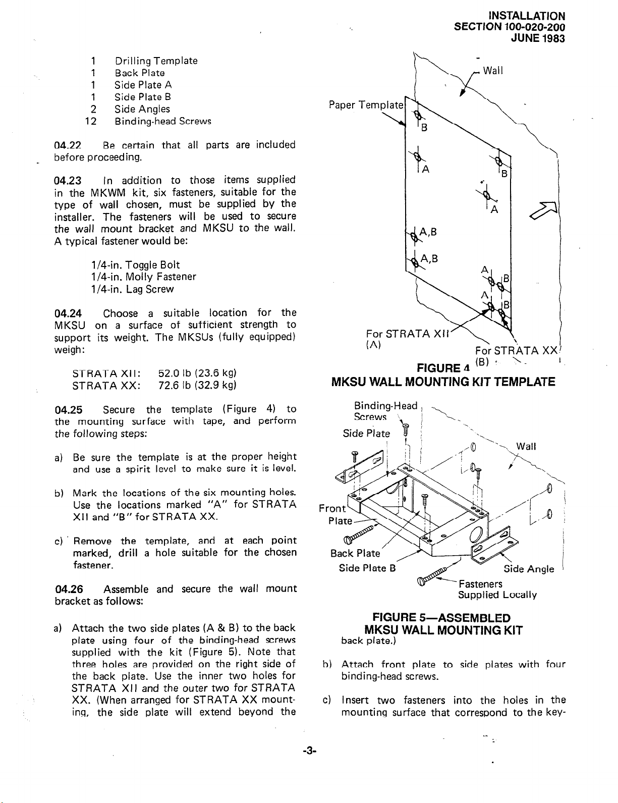
04.23
in the MKWM kit, six fasteners, suitable for the
type of wall chosen, must be supplied by the
installer. The fasteners will
the wall mount bracket and
A typical fastener would be:
04.24
MKSU on a surface of sufficient strength to
support its weight. The MKSUs (fully equipped)
weigh
STRATA Xl I:
STRATA XX:
04.25
the mounting surface with tape, and perform
the following steps:
Be sure the template is at the proper height
a)
and use a spirit level to make sure it is level.
In addition to those items supplied
be used to secure
MKSU to the wall.
l/4-in. Toggle Bolt
l/4-in. Molly Fastener
l/4-in. Lag Screw
Choose a suitable location for the
:
52.0 lb (23.6 kg)
72.6 lb (32.9 kg)
Secure the template (Figure 4) to
A,B
%
For STRATA Xl I
.
(A)
FIGURE
Fo\r STRATA XX
4 IB) * ‘- ’
‘t
MKSU WALL MOUNTING KIT TEMPLATE
Binding-Head , ,
Screws
Side Plate
J i A._
-
B
.
Mark the locations of the six mounting holes.
b)
Use the locations marked “A” for STRATA
Xl I and “B” for STRATA XX.
Remove the template, and at each point
c)
marked, drill a hole suitable for the chosen
fastener.
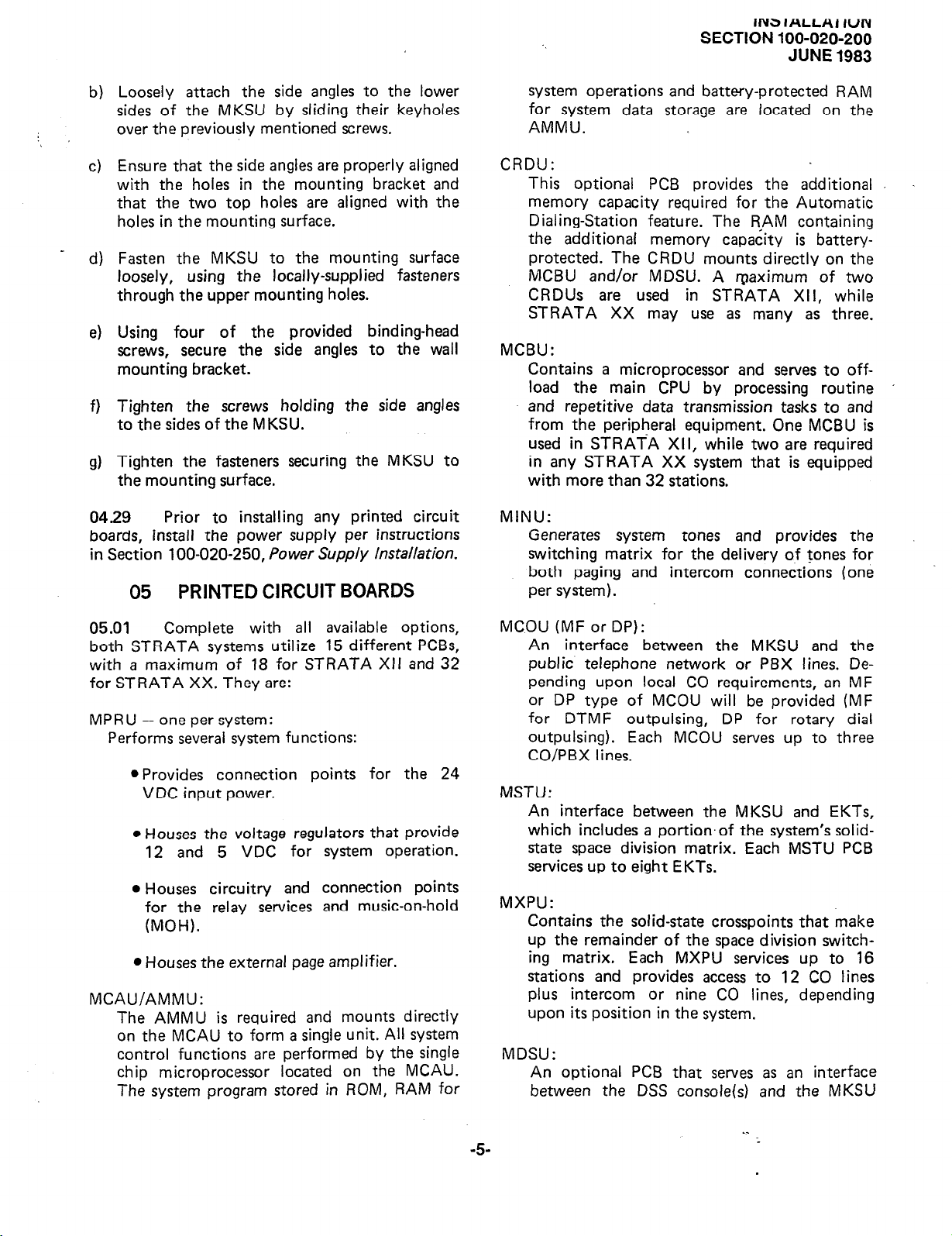
04.26
bracket as follows:
a) Attach the two side plates (A & B) to the back
plate using four of the binding-head screws
supplied with the kit (Figure 5). Note that
three holes are provided on the right side of
the back plate. Use the inner two holes for
STRATA XII and the outer two for STRATA
XX. (When arranged for STRATA XX mount-
ing, the side plate will extend beyond the
Assemble and secure the wall mount
Back Plate’
Side Plate B
w----
Fasteners
Supplied Locally
Side Angle
FIGURE 5-ASSEMBLED
MKSU WALL MOUNTING KIT
back plate.)
b) Attach front plate to side plates with four
binding-head screws.
c) Insert two fasteners into the holes in the
mounting surface that correspond to the key-
-3-

INSTALLATION
SECTION 100-020-200
JUNE 1983
holes in the back plate. Tighten them loosely
so that approximately 3/8-in. gap remains between the head of the fastener and the mounting surface.
install the wall mount assembly by slipping
d)
the two keyholes in the back plate over the
two fasteners installed in Step C.
Install the lower two fasteners in the back
e)
plate and tighten all four fasteners securing
the wall mount assembly.
04.27
mounting by reversing the back cover. This will
locate the two mounting holes at the top of the
MKSU. To reverse the back cover, proceed as
follows:
a)
b)
The MKSU must be prepared for wall
Loosen all seven screws securing
cover (Figure 6).
Remove and save the three screws
in Figure 6, lift the back cover off.
the back
indicated
FIGURE 7-MKSU
Reinstall the back cover. Secure
d)
four loosened screws.
Reinstall and tighten the three
e)
moved earlier.
04.28 Refer to Figure 8, and complete the
wall mount installation as follows:
FASTENERS
SUPP,LIED LOCALLY
it with the
screws re-
FIGURE 6-MKSU
c) Rotate the back cover 180” and realign it so
the two mounting holes project above the
MKSU (Figure 7).
FIGURE 8-MKSU
a) Rest the MKSU on the wall mount assembly
and loosen the two screws located near the
bottom of each side of the MKSU.
-4-
WALL
’
INS IALLHl IUN
SECTION 100-020-200
JUNE 1983
Loosely attach the side angles to the lower
b)
sides of the MKSU by sliding their keyholes
:
over the previously mentioned screws.
Ensure that the side angles are properly aligned
c)
with the holes in the mounting bracket and
that the two top holes are aligned with the
holes in the mounting surface.
Fasten the MKSU to the mounting surface
d)
loosely, using the locally-supplied fasteners
through the upper mounting holes.
Using four of the provided binding-head
e)
screws, secure the side angles to the wall
mounting bracket.
Tighten the screws holding the side angles
f)
to the sides of the MKSU.
Tighten the fasteners securing the MKSU to
Cl)
the mounting surface.
04.29
boards, install the power supply per instructions
in Section 100-020-250, Power Supply Installation.
Prior to installing any printed circuit
05
PRINTED CIRCUIT BOARDS
system operations and battery-protected RAM
for system data storage are located on the
AMMU.
CRDU:
This optional PCB provides the additional
memory capacity required for the Automatic
Dialing-Station feature. The RAM containing
the additional memory capacity is battery-
protected. The CRDU mounts directly on the
MCBU and/or MDSU. A maximum of two
CRDUs are used in STRATA XII, while
STRATA XX may use as many as three.
MCBU:
Contains a microprocessor and serves to off-
load the main CPU by processing routine
and repetitive data transmission tasks to and
from the peripheral equipment. One MCBU is
used in STRATA XII, while two are required
in any STRATA XX system that is equipped
with more than 32 stations.
MINU:
Generates system tones and provides the
switching matrix for the delivery of tones for
both paging and intercom connections (one
per system).
05.01
both STRATA systems utilize 15 different PCBs,
with a maximum of 18 for STRATA XII and 32
for STRATA XX. They are:
MPRU - one per system:
Performs several system functions:
MCAU/AMMU:
The AMMU is required and mounts directly
on the MCAU to form a single unit. All system
control functions are performed by the single
chip microprocessor located on the MCAU.
The system program stored in ROM, RAM for
Complete with all available options,
l
Provides connection points for the 24
VDC input power.
l
Houses the voltage regulators that provide
12 and 5 VDC for system operation.
l
Houses circuitry and connection points
for the relay services and music-on-hold
(MOH).
l
Houses the external page amplifier.
MCOU (MF or DP):
An interface between the MKSU and the
public telephone network or PBX lines. Depending upon local CO requirements, an MF
or DP type of MCOU will be provided (MF
for DTMF outpulsing, DP for rotary dial
outpulsing). Each MCOU serves up to three
CO/PBX lines.
MSTU:
An interface between the MKSU and EKTs,
which includes a portion.of the system’s solidstate space division matrix. Each MSTU PCB
services up to eight EKTs.
MXPU:
Contains the solid-state crosspoints that make
up the remainder of the space division switching matrix. Each MXPU services up to 16
stations and provides access to 12 CO lines
plus intercom or nine CO lines, depending
upon its position in the system.
MDSU:
An optional PCB that serves as an interface
between the DSS console(s) and the MKSU
-5-
INSTALLATION
SECTION 100-020-200
JUNE 1983
(each system uses only one MDSU). The MDSU
serves up to two fully functional DSS consoles
and two DSS consoles which are used as Busy
Lamp Field terminals only.
MSMU/S&J:
The SCNU is required and mounts directly
on the MSMU to form a single unit. This
optional PC6 serves as an interface between
the MKSU and a printer or storage device
used for the SMDR feature. The PCB is equip-
ped with an RS 232C-type interface (one
per system).
MOPU (MF/DP or DP):
An optional PCB that serves as an interface
between the MKSU and conventional, single
line telephones or
(OPX) lines. An MOPU DP will operate with
rotary dial telephones only. Either DTMF or
rotary dial telephones can be used with an
MOPU MF/DP PCB. Each MOPU services
two extensions. A maximum of two MOPUs
can be installed in STRATA XII and three
in STRATA XX.
off-premise extension
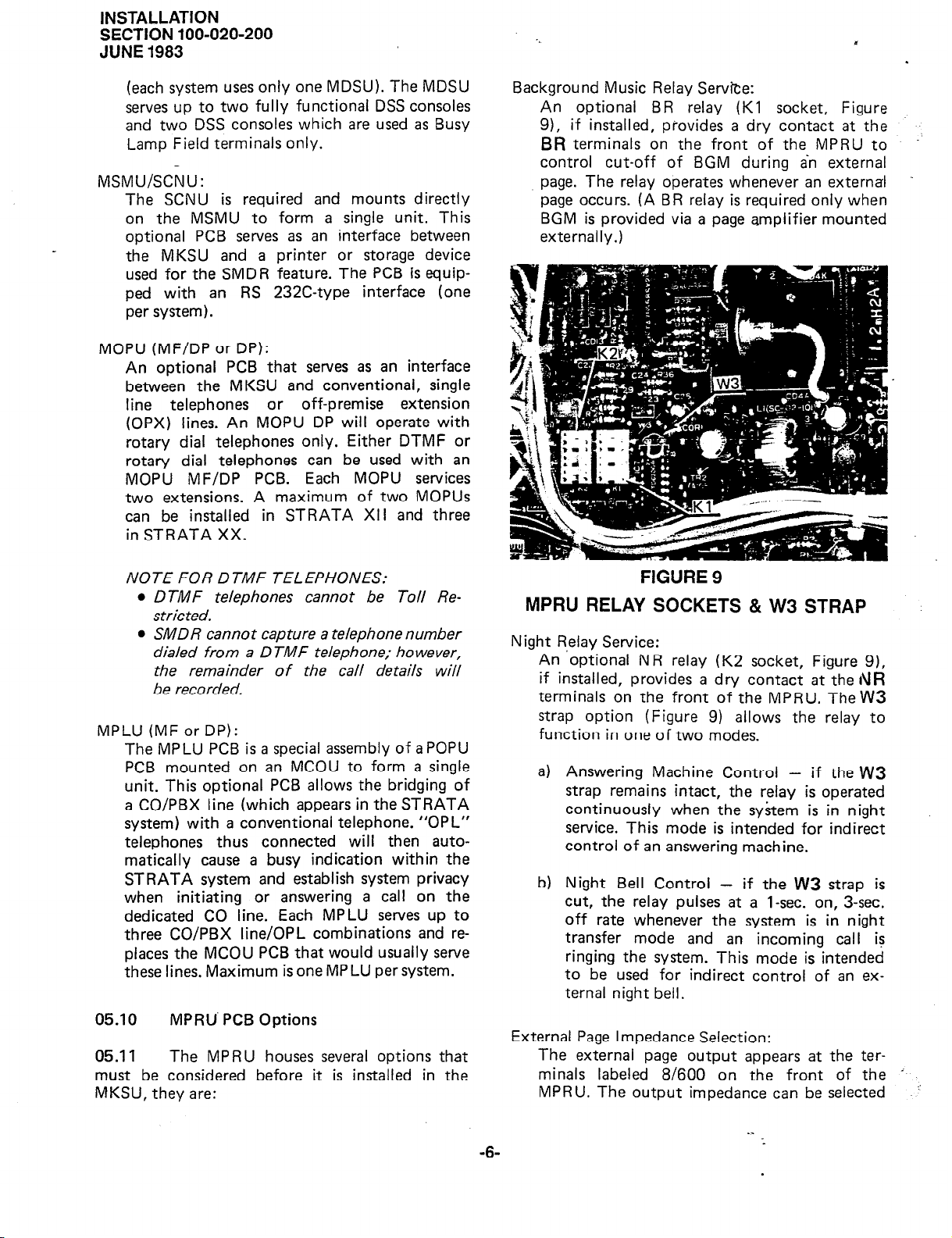
Background Music Relay Service:
An optional BR relay (Kl socket, Figure
9), if installed, piovides a dry contact at the
BR terminals on the front of the MPRU to
control cut-off of BGM during an external
page. The relay operates whenever an external
page occurs. (A BR relay is required only when
BGM is provided via a page amplifier mounted
externally.)
NOTE FOR DTMF TELEPHONES:
l
DTMF telephones cannot be Toll Restricted.
l
SK40 R cannot capture a telephone number
dialed from a D TMF telephone; however,
the remainder of the call details will
be recorded.
MPLU (MF or DP):
The MPLU PCB is a special assembly of a POPU
PCB mounted on an MCOU to form a single
unit. This optional PCB allows the bridging of
a CO/PBX line (which appears in the STRATA
system) with a conventional telephone. “OPL”
telephones thus connected will then automatically cause a busy indication within the
STRATA system and establish system privacy
when initiating or answering a call on the
dedicated CO line. Each MPLU serves up to
three CO/PBX line/OPL combinations and replaces the MCOU PCB that would usually serve
these lines. Maximum is one MP LU per system.
05.10
05.11
must be considered before it is installed in the
MKSU, they are:
MPRU’ PCB
The MPRU houses several options that
Options
FIGURE 9
MPRU RELAY SOCKETS & W3 STRAP
Night Relay Service:
An ‘optional NR relay (K2 socket, Figure 9),
if installed, provides a dry contact at the
terminals on the front of the MPRU. TheW3
strap option (Figure 9) allows the relay to
function in one of two modes.
Answering Machine Control - if the
a)
strap remains intact, the relay is operated
continuously when the system is in night
service. This mode is intended for indirect
control of an answering machine.
Night Bell Control - if the
b)
cut, the relay pulses at a 1-sec. on, 3-sec.
off rate whenever the system is in night
transfer mode and an incoming call is
ringing the system. This mode is intended
to be used for indirect control of an external night bell.
External Page Impedance Selection:
The external page output appears at the ter-
minals labeled 8/600 on the front of the
MPRU. The output impedance can be selected
W3
rVR
W3
strap is
i
-’
-6-
 Loading...