

Page 1
TOSHIBA
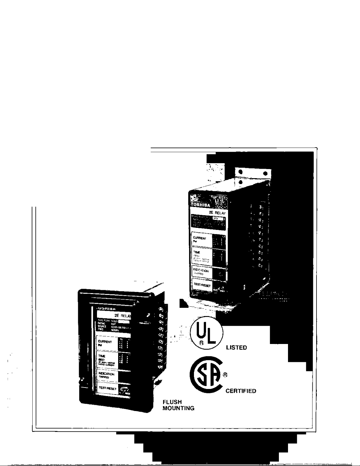
2E MOTOR PROTECTION RELAYS
MODEL
■ OVERLOAD & SINGLE-PHASE
PROTECTION
■ SOLID-STATE
■ lUIANUAL TEST FEATURE
■ MANUAL/REMOTE/AUTO RESET
■ SURFACE/FLUSH MOUNTING
RC8SO
Page 2
2E MOTOR PROTECTION R^AYS
MODEL
Toshiba’s 2E relay eliminates many motor
failures. Thissolid state relay features precise
motor protection for any horsepower/voltage
combination in just three ratings. The 2E
provides overload and single phase protection
and has an adjustable setting for very wide
FEATURES
■ OVERLOAD & SINGLE-PHASE PROTECTION
Two protective functions are incorporated.
■ SOLID-STATE
Fully solid-state circuit provides high reliability and
precise operation.
■ MANUAL TEST FEATURE
Manual test switch offers convenience for sequence
testing.
■ MANUAL/REMOTE/AUTO RESET
Wide selection of reset mode gives application
flexibility.
range from 3 to 40 sec. (starting characteristic,
at 600% current) to accomodate reduced voltage
start-ups and high inertia loads.
The 2E relay complies with international
standards as well as UL (USA) listed and CSA
(Canada) certified.
ISURFACE/FLUSH MOUNTING
Selectable surface or flush mounting,
I FLEXIBILITY
The relay allows for a high degree of flexibility for
coordinating with wide range of current and trip time
settings.
I VISIBLE TRIP INDICATOR
LED indicator shows relay trip status dearly until reset.
I INTERNATIONALLY RECOGNIZED
The relay complies with international standards as well
as UL (USA) listed and CSA (Canada) certified.
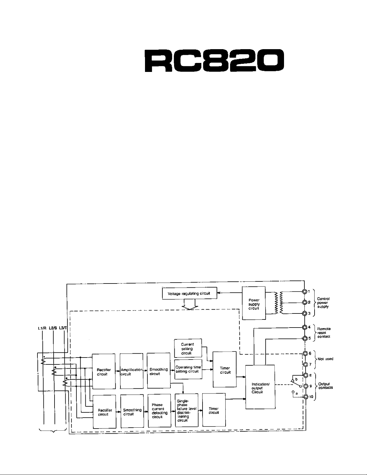
Load circuit
Page 3
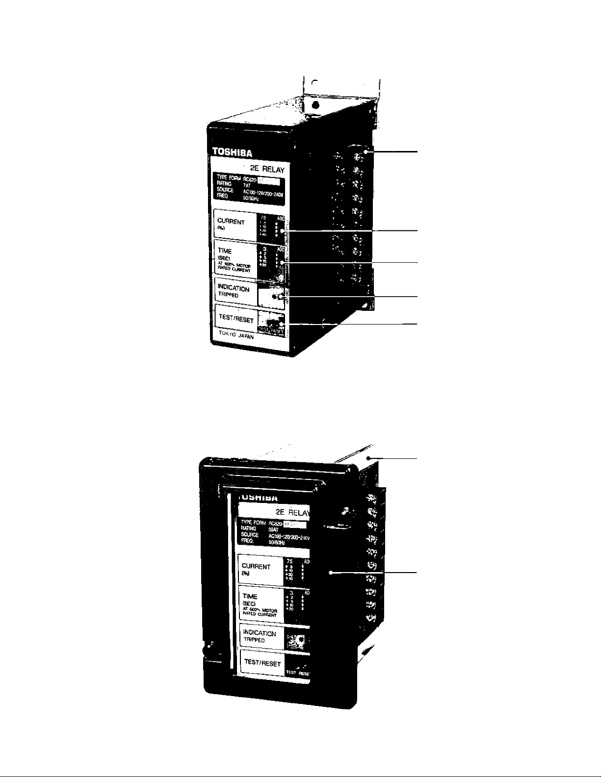
CONTROL TERMINALS
CURRENT SETTING
TRIP TIME SETTING
LED TRIP INDICATOR
TEST/RESET SWITCH
(SPRING RETURN)
FLUSH MOUNTING FEET
FLUSH COVER
Page 4

NOMENCLATURE RC820—HP 1 Y 12
(1) {2) (3) {4) (5)
(1) Model (Series) No. RC820
(2) Reset Mode HP ... Manual Reset
AP,,.. Auto Reset
(3) Current Rating 1
(4) Control Volt. Y
..................
2
......
3
......
.......
7 AT
55 AT
110 AT
100-120/200-240 V AC
(5) Variation — Standard Surface Mounting
2
.......
Rush Mounting
12 .... Remote Reset (Standard)
72.... Remote Reset
(UL Listed/CSA Certified)
RATINGS & SPECIFICATIONS
SELECTION
RESET
MANUAL
AUTO
REMOTE SURFACE
MOUNTING UL & CSA
SURFACE YES
FLUSH
SURFACE YES RC820-APL'
MODEL NO.
RC820-HPL';:;jY
NO RC820-HPL
NO
YES
RC820-HPÌ':;;iYi2
RC820-HPL::ìy72
;:]Y2
:;:iY
Applicable Circuit
Rated Current
Overload Protection
Single-Phase Protection
Control Power
Rated Ampere-turns (AT)
Setting Range
Ultimate Operating
Current
Trip Time Setting Range
Operating Time
Accuracy
Minimum Operating
Current
Operating Time
Rating
RC820-
HP1Y
AP1Y
RC820-
HP2Y
AP2Y
RC820-
HP3Y
AP3Y
Three-phase circuit rated up to 600V AC, 50/60 Hz—Direct
(Also, applicable to high-voltage circuit by combining with highvoltage CT)
7AT
55AT
11 OAT
75—150% of rated AT
105—125% of setting current
3—40 sec. for starting characteristics at 600% of setting current
±20% of setting time
85% of setting current under one-phase completely loss (When
measured on either remaining phase).
Less than 4 sec.
100—120V/200—240 V AC, ^<l>, 50/60 Hz
Power Consumption
Output Contact Capacity
Weight
Allowable Volt.
Fluctuation
Control Power Circuit
Detecting (CT) Circuit
1 ICo^ctTArrangement
Contact Capacity
85%—110%
2 VA
0.3 VA/phase at rated current
1 NO—NC (SPDT/Form C)
120V AC-5.0A (Resistive load)
120 V AC-3.0A (Inductive load, pf = 0.40)
125V DO0.2A (L/R = 7ms)
250V DC-0.1A (UR = 7ms)
NEMA B300
Approx. 1 kg (2.2 lbs.)
Page 5

OPERATING CHARACTERISTIC CURVE
MULTIPLES OF LOAD CURRENT
STARTING CHARACTERISTIC
(Notes) (1) Overload operating ctiaracteristics
Ultimate operating current—105—125% of setting current
(2) Single-phase operating characteristics
Min. operating current—85% of setting current
MULTIPLES OF LOAD CURRENT
► RUNNING CHARACTERISTIC
Page 6

INSTALLATION
40(1.58)
-----
60(2.36),
76 (3.66)
16
(0.63)
5 (0.20)
Dta-4
Mounting
Hoies
-----
—C
(1.58)
Unit; mm {in)
^
----
40
SURFACE MOUNTING
Mounting Pane!
(0.06 Min—0.125 Max.)
FLUSH MOUNTING
6
Page 7

WIRING
Low-vo(tage power supply
600 V AC or less
I WOTOn
-Sh
Low-voltage
Contractor
2E Relay
(Notes)
^Stop
Start
iJ\Operatìng
Xoil
I Ì I a I 3 I 4 15 [ 5 I 7 f
L/
"Connections of control power source
AC 100-120V—Terminals 1-2
AC 200-240V—Terminals 1-3
For other voit., use CPT.
"‘Connections of output contacts
NC“Oontact {opened when the 2E
Relay operated)—Terminals 8-9
NO-contact (closed when the 2E
Relay operated)—Terminals 9-10
“‘Connections of Remote reset switch
LOW-VOLTAGE
Control
Tsrminal
Numbers
Higti-voltaga power supply PT w control transformer
2.AKV—13.8K\/ AC /[100~t20V Sacondaiy)
High
voltage
CT
|_High-vortag©
^ contactor
__
i|i
l|2[3Ì4|5Ì6|7|a|9|To
I 2£ Relay
P\
o
Hlgh“V0ita9& CT sscondar/ circuit
wires pass through the windows of
the built-in CT's,
HIGH-VOLTAGE
^ stop
^ Start
15 Operating
' Coll
b a
HOW TO SET
Selection of the suitable model may require some preli
minary calculations. See “Current Setting” to determine
if the calculated “Current Setting %” can be obtained
with the selected model given the motor full load current
(FLA). Model Selection can also be influenced by wire
size which limits the number of turns that can be passed
through the CT windows.
(1) Current Setting
N{g-i
N(T) = Number of wire turns through 2E built-in CTs,
/m .0 4*- FLAxNxIOO
Notes: * Select the external CT ratio so that the current
(2E AT Rating)X(External CT Ratio)
-------------------------
----------------------------
round off to nearest integer.
® "^9 0) ^2^ yjj p3(jpg| ^ (External CT Ratio)
setting % is as close to 100% as possible.
If no external CT are used, substitute with
“1.0”.
**For 1.15 Service Factor Motors. If the motor
has a 1.0 S.F. multiply the calculated “Current
Setting %” by 0,93, (Practice in USA)
Example: 200HP, 460V, 240A Full Load. 1.15 S.F.
Across-the-line start.
240 Amps exceeds the highest rated 2E
Relay, therefore, external CT’s must be
used, and the HPIY, 7 AT rated 2E, will be
chosen as the standard model when the
current exceeds the HP3Y’s rating. If 300/5
CT’s are used,
41, m 4 0,4- n/ 240xNfT)x100%
the Current Setting % =
------------7x(M0)
--------------
= N01x57.14%.
And if 2 turns through the 2E Relay’s CT
windows (from the external CT’s) are used,
the % Dial
Setting = 2x57.14=114% = 110% or 115%
(2) Time setting
Determine the protection curve from 2E Relay
operating curves, and read the operating time at 600%
of setting current. Adjust the time setting dip switch
to the nearest setting above the operating time.
5"'
Page 8

ORDERING INFORMATION
When ordering specify;
■ Model No. & Quantity
■ Any Special Requirement
Tostliba International Corporation:
Houston, Vancouver
TOSHIBA
TOSHIBA CORPORATIOISJ
Industrial Equiprirent Department
1 - 1 . SHIBAURA 1 -CHOME, MINATO-KU, TOKYO. 1 D5. JAPAN
phone: 3457-.daoO. FAX: SA aa -a BB B
• For further information, please contact your nearest Toshiba Liaison Representative pr internatipnai Operations—Producer Goods.
• The data given in this catalog are subject to change without notice.
Toshiba International Corporation
Pty. Ltd,: Sydney, Melbourne
Toshiba Intematlonal {Europe) Ltd.
'as-ia(NA)7oa*3
Printed in Japan
 Loading...