

Toshiba D-R560KU, D-R560 - DVD Recorder With TV Tuner Owner's Manual
D-R560KU
Printed in China
1VMN24693 / E7M70UD
TOSHIBA DVD VIDEO RECORDER
DVD VIDEO RECORDER
D-R560KU
OWNER’S MANUAL
Management
Disc
Recording PlaybackIntroduction Connections Basic Setup Editing Function Setup Others
Owner’s Record
The model number and serial number are on the back
of your DVD Recorder. Record these numbers in the spaces
below. Refer to these numbers whenever you
communicate with your Toshiba dealer about this DVD
Recorder.
Model number:
© 2008 Toshiba Corporation
E7M70UD_D-R560KU_cover.indd 2-3E7M70UD_D-R560KU_cover.indd 2-3 2007/12/19 21:38:302007/12/19 21:38:30
Serial number:
PRECAUTIONS
WARNING:
TO REDUCE THE RISK OF FIRE OR ELECTRIC SHOCK, DO NOT EXPOSE THIS
APPLIANCE TO RAIN OR MOISTURE.
CAUTION
RISK OF ELECTRIC SHOCK
DO NOT OPEN
CAUTION
TO REDUCE THE RISK OF ELECTRIC SHOCK, DO NOT
REMOVE COVER (OR BACK). NO USER SERVICEABLE
PARTS INSIDE. REFER SERVICING TO QUALIFIED
SERVICE PERSONNEL.
Laser Safety
This unit employs a laser. Only a qualified service person should remove the cover or attempt to service this device,
due to possible eye injury.
CAUTION: USE OF CONTROLS OR ADJUSTMENTS OR PERFORMANCE OF PROCEDURES OTHER THAN THOSE
CAUTION:
LOCATION: INSIDE, NEAR THE DECK MECHANISM.
FCC WARNING- This equipment may generate or use radio frequency energy. Changes or modifications to this
equipment may cause harmful interference unless the modifications are expressly approved in the manual. The
user could lose the authority to operate this equipment if an unauthorized change or modification is made.
RADIO-TV INTERFERENCE
This equipment has been tested and found to comply with the limits for a Class B digital device, pursuant to Part 15 of
the FCC Rules. These limits are designed to provide reasonable protection against harmful interference in a residential
installation. This equipment generates, uses, and can radiate radio frequency energy and, if not installed and used in
accordance with the instructions, may cause harmful interference to radio communications. However, there is no
guarantee that interference will not occur in a particular installation. If this equipment does cause harmful interference
to radio or television reception, which can be determined by turning the equipment off and on, the user is encouraged
to try to correct the interference by one or more of the following measures:
1) Reorient or relocate the receiving antenna.
2) Increase the separation between the equipment and receiver.
3) Connect the equipment into an outlet on a circuit different from that to which the receiver is connected.
4) Consult the dealer or an experienced radio/TV technician for help.
This Class B digital apparatus complies with Canadian ICES-003.
Cet appareil numérique de la classe B est conforme à la norme NMB-003 du Canada.
:
The caution marking is located on the rear of the cabinet.
SPECIFIED HEREIN MAY RESULT IN HAZARDOUS RADIATION EXPOSURE.
VISIBLE AND INVISIBLE LASER RADIATION WHEN OPEN AND INTERLOCK DEFEATED. DO NOT STARE INTO BEAM.
The lightning flash with arrowhead symbol, within an
equilateral triangle, is intended to alert the user to the
presence of uninsulated “dangerous voltage” within
the product’s enclosure that may be of sufficient magnitude to constitute a risk of electric shock to persons.
The exclamation point within an equilateral triangle
is intended to alert the user to the presence of important operating and maintenance (servicing) instructions in the literature accompanying the appliance.
CAUTION: TO PREVENT ELECTRIC SHOCK, MATCH WIDE BLADE OF PLUG TO WIDE SLOT, FULLY INSERT.
ATTENTION:
POUR ÉVITER LES CHOCS ÉLECTRIQUES, INTRODUIRE LA LAME LA PLUS LARGE DE LA FICHE DANS LA
BORNE CORRESPONDANTE DE LA PRISE ET POUSSER JUSQU’AU FOND
.
A NOTE ABOUT RECYCLING
This product’s packaging materials are recyclable and can be reused. Please dispose of any materials in accordance
with your local recycling regulations.
Batteries should never be thrown away or incinerated but disposed of in accordance with your local regulations
concerning chemical wastes.
Make your contribution to the environment!!!
• Used up batteries do not belong in the dust bin.
• You can dispose of them at a collection point for used up batteries or special waste.
Contact your council for details.
2EN2EN
E7M70UD_D-R560KU_EN.indd 2E7M70UD_D-R560KU_EN.indd 2 2007/12/17 11:11:192007/12/17 11:11:19
PRECAUTIONS
IMPORTANT SAFETY INSTRUCTIONS
This unit has been designed and manufactured to assure personal safety. Improper use can result in electric shock or fire hazard.
The safeguards incorporated in this unit will protect you if you observe the following procedures for installation, use and
servicing. This unit is fully transistorized and does not contain any parts that can be repaired by the user.
DO NOT REMOVE THE CABINET COVER, OR YOU MAY BE EXPOSED TO DANGEROUS VOLTAGE. REFER SERVICING TO
QUALIFIED SERVICE PERSONNEL ONLY.
Introduction
Connections Basic Setup
1. Read these instructions.
2. Keep these instructions.
3. Heed all warnings.
4. Follow all instructions.
5. Do not use this apparatus near water.
6. Clean only with dry cloth.
7. Do not block any ventilation openings. Install in
accordance with the manufacturer’s instructions.
8. Do not install near any heat sources such as radiators,
heat registers, stoves, or other apparatus (including
amplifiers) that produce heat.
9. Do not defeat the safety purpose of the polarized or
grounding-type plug. A polarized plug has two blades
with one wider than the other. A grounding type plug
has two blades and a third grounding prong. The wide
blade or the third prong are provided for your safety. If
the provided plug does not fit into your outlet, consult
an electrician for replacement of the obsolete outlet.
10. Protect the power cord from being walked on or pinched
particularly at plugs, convenience receptacles, and the
point where they exit from the apparatus.
11. Only use attachments/accessories specified by the
manufacturer.
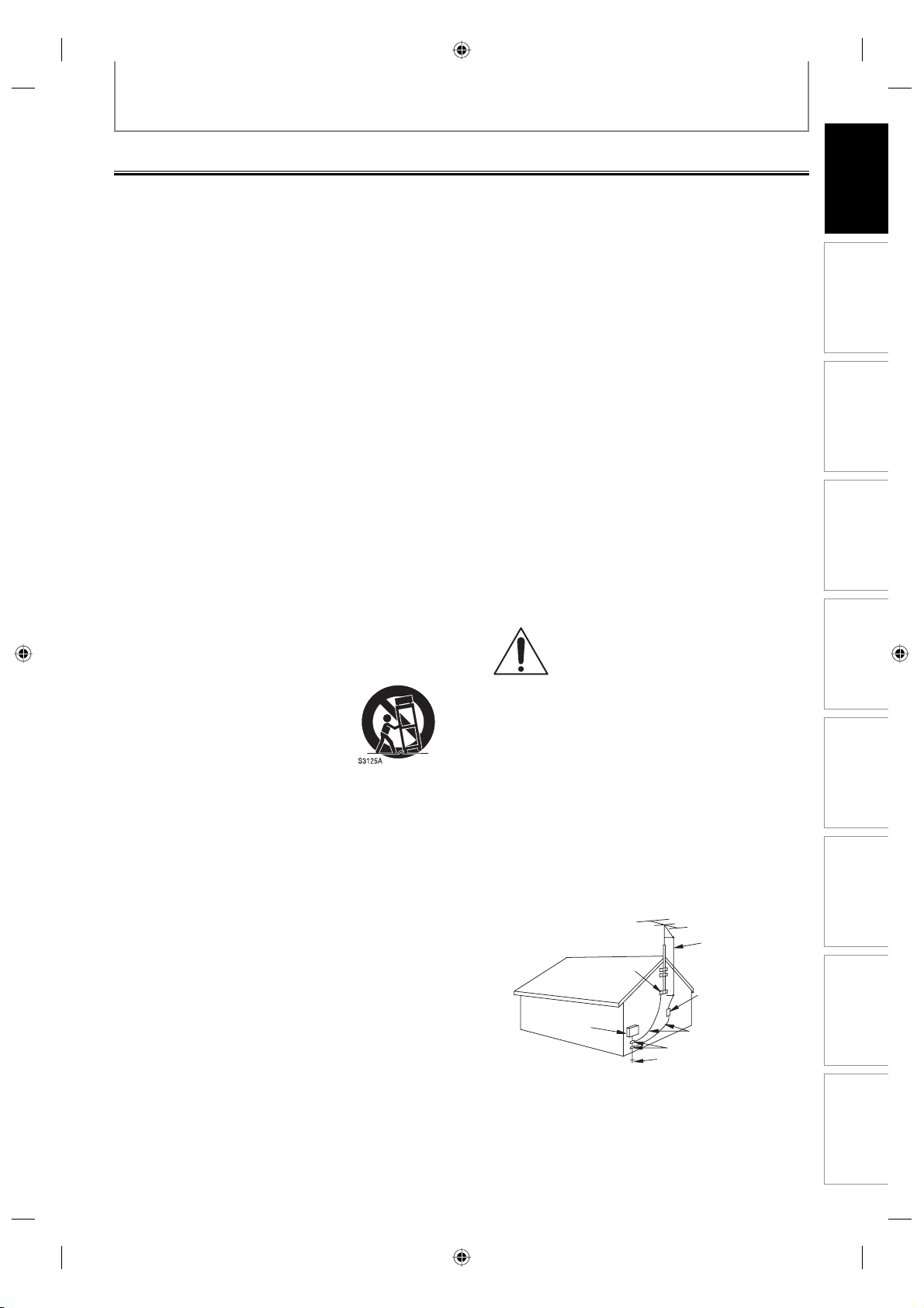
12. Use only with the cart, stand, tripod,
bracket, or table specified by the
manufacturer, or sold with the
apparatus. When a cart is used, use
caution when moving the cart/
apparatus combination to avoid injury
from tip-over.
13. Unplug this apparatus and disconnect the antenna or
cable system during lightning storms or when unused
for long periods of time.
14. Refer all servicing to qualified service personnel.
Servicing is required when the apparatus has been
damaged in any way, such as power-supply cord or plug
is damaged, liquid has been spilled or objects have fallen
into the apparatus, the apparatus has been exposed to
rain or moisture, does not operate normally, or has been
dropped.
15. Do not overload wall outlets; extension cords, or integral
convenience receptacles as this can result in a risk of fire
or electric shock.
16. Never expose the apparatus to dripping or splashing or
place items such as vases, aquariums, any other item
filled with liquid, or candles on top of the unit.
Keep your fingers well clear of the disc tray as it is closing.
17.
Neglecting to do so may cause serious personal injury.
18. Do not place anything on top of this unit.
19. Do not place the apparatus on amplifiers or equipment
that may produce heat.
20. Never block or cover the slots or openings in the unit.
Never place the unit:
• on a bed, sofa, rug, or similar surface;
• too close to drapes, curtains, or walls; or
• in a confined space such as a bookcase, built-in cabinet,
or any other place with poor ventilation.
The slots and openings are provided to protect the unit
from overheating and to help maintain reliable operation.
21. Do not use a cracked, deformed, or repaired disc. These
discs are easily broken and may cause serious personal
injury and apparatus malfunction.
22. If the apparatus should emit smoke or an unusual odor,
immediately disconnect the power cord from the wall
outlet. Wait until the smoke or smell stops, then ask your
dealer for a check and repair. Neglecting to do so may
cause fire.
23. During thunderstorms, do not touch the connecting
cables or the apparatus.
24.
DANGER: RISK OF SERIOUS
PERSONAL INJURY OR DEATH!
• Use extreme care to make sure you are never in a
position where your body (or any item you are in
contact with, such as a ladder or screwdriver) can
accidentally touch overhead power lines. Never locate
the antenna near overhead power lines or other
electrical circuits.
• Never attempt to install any of the following during
lightning activity: a) an antenna system; or b) cables,
wires, or any home theater component connected to an
antenna or phone system.
25. Always make sure the antenna system is properly
grounded to provide adequate protection against
voltage surges and built-up static charges (see Section
810 of the National Electric Code).
EXAMPLE OF ANTENNA GROUNDING
AS PER NATIONAL ELECTRICAL CODE
GROUND
CLAMP
ELECTRIC
SERVICE
EQUIPMENT
NEC – NATIONAL ELECTRICAL CODE
S2898A
ANTENNA
LEAD
WIRE
ANTENNA
DISCHARGE UNIT
(NEC SECTION 810-20)
GROUNDING CONDUCTORS
(NEC SECTION 810-21)
GROUND CLAMP
POWER SERVICE GROUNDING
ELECTRODE SYSTEM
(NEC ART 250, PART H)
Management
Disc
Recording
Playback
Editing Function Setup
Others
3EN 3EN
E7M70UD_D-R560KU_EN.indd 3E7M70UD_D-R560KU_EN.indd 3 2007/12/17 11:11:202007/12/17 11:11:20

PRECAUTIONS
Installation Location
For safety and optimum performance of this unit:
• Install the unit in a horizontal and stable position. Do
not place anything directly on top of the unit. Do not
place the unit directly on top of the TV.
• Shield it from direct sunlight and keep it away from
devices of intense heat. Avoid dusty or humid places.
Avoid places with insufficient ventilation for proper
heat dissipation. Do not block the ventilation holes on
the sides of the unit. Avoid locations subject to strong
vibration or strong magnetic fields.
Avoid the Hazards of Electrical Shock and Fire
• Do not handle the power cord with wet hands.
• Do not pull on the power cord when disconnecting it
from AC outlet. Grasp it by the plug.
• If, by accident, water is spilled on this unit, unplug
the power cord immediately and take the unit to our
Authorized Service Center for servicing.
Moisture Condensation Warning
Moisture condensation may occur inside the unit when it
is moved from a cold place to a warm place or after
heating a cold room or under conditions of high
humidity. Do not use this unit at least for 2 hours until its
inside gets dry.
Supplied Accessories
remote control with batteries (AAx2)
RF coaxial cable
RCA audio/video cables
owner’s manual
About Copyright
The unauthorized recording, use, distribution, or revision
of television programs, videotapes, DVDs and other
materials, is prohibited under the copyright laws of the
United States and other countries, and may subject you
to civil and/or criminal liability.
This product incorporates copyright protection
technology that is protected by U.S. patents and other
intellectual property rights. Use of this copyright
protection technology must be authorized by
Macrovision, and is intended for home and other
limited viewing uses only unless otherwise authorized
by Macrovision. Reverse engineering or disassembly is
prohibited.
Notice for Progressive Scan Output
Consumers should note that not all high definition
television sets are fully compatible with this product and
may cause artifacts to be displayed in the picture. In case
of picture problems with 480 progressive scan output, it
is recommended that the user switch the connection to
the “standard definition” output. If there are questions
regarding your TV set compatibility with this 480p DVD
recorder, please contact Toshiba Customer Service.
OWNER’S MANUAL
quick setup guide
return stop sheet
4EN4EN
E7M70UD_D-R560KU_EN.indd 4E7M70UD_D-R560KU_EN.indd 4 2007/12/17 11:11:202007/12/17 11:11:20
Maintenance
PRECAUTIONS
Introduction
IR Signal Check
Servicing
• Please refer to relevant topics on “TROUBLESHOOTING”
on pages 108-111 before returning the product.
• If you need to call a customer service representative,
please know the model number and serial number of
your product before you call. This information is
displayed on the back of the product. Also, please take
a moment to identify the problem you are having, and
be prepared to explain this to the representative. If you
believe the representative will need to help you with
operations, please stay near the product. Our
representatives will be happy to assist you.
Cleaning the Cabinet
• Wipe the front panel and other exterior surfaces of the
unit with a soft, slightly damp cloth.
• Never use a solvent, thinner, benzene or alcohol to
clean the unit. Do not spray insecticide liquid near the
unit. Such chemicals may discolor the surface or
damage the unit.
Cleaning Discs
• When a disc becomes dirty, clean it with a cleaning
cloth. Wipe the disc from the center to out. Do not
wipe in a circular motion.
• Do not use solvents such as benzine, thinner,
commercially available cleaners, detergent, abrasive
cleaning agents or antistatic spray intended for analog
records.
Cleaning the Disc Lens
• If this unit still does not perform properly although you
refer to the relevant sections and to
“TROUBLESHOOTING” in this owner’s manual, the laser
optical pickup unit may be dirty. Consult your dealer or
an Authorized Service Center for inspection and
cleaning of the laser optical pickup unit.
Disc Handling
• Handle the discs so that fingerprints and dust do not
adhere to the surfaces of the discs.
• Always store the disc in its protective case when it is
not used.
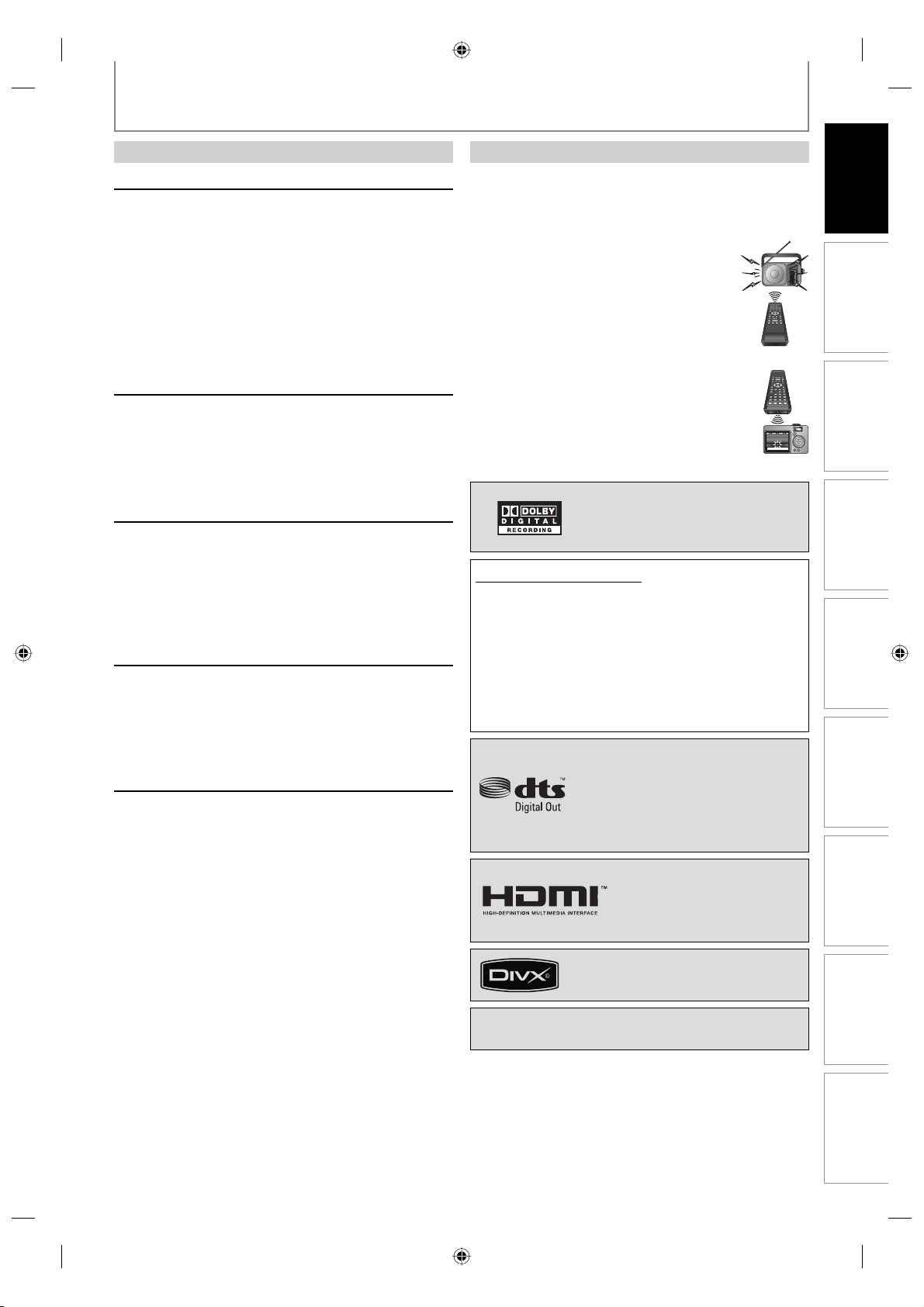
If the remote control does not work properly, you can test if
the remote control sends out the infrared signal with AM
radio or a digital camera (including built-in camera of cellular
phone). It will help to define the cause of malfunction.
• With an AM radio:
Tune an AM radio to a station with no
broadcasting. Press a button on remote
control toward the radio. Sound will be
fluttering when you press any key and the
radio receives the signal. This means the
remote control is working.
• With a digital camera (including built-in camera of
cellular phone):
Direct a digital camera to remote control,
press and hold a button on remote control. If
infrared light appears through digital camera,
the remote control is working.
Manufactured under license from
Dolby Laboratories. Dolby and the
double-D symbol are trademarks of
Dolby Laboratories.
Dolby Digital Recording
“Dolby® Digital Recording enables consumers to record
high-quality video with stereo sound on recordable DVD
discs. The technology, when utilized instead of PCM
recording, also saves recordable disc space, allowing for
higher video resolution or extended recording time on
each DVD. DVDs created using Dolby Digital Recording
will play back on all DVD-video players.”
Note: This is true when the players are compatible with
actual recordable DVD discs.
Manufactured under license under U.S.
Patent #: 5,451,942 & other U.S. and
worldwide patents issued & pending.
DTS and DTS Digital Out are registered
trademarks and the DTS logos and
Symbol are trademarks of DTS, Inc.
©1996-2007 DTS, Inc. All Rights Reserved.
HDMI, the HDMI logo and HighDefinition Multimedia Interface
are trademarks or registered
trademarks of HDMI Licensing
LLC.
Connections Basic Setup
Management
Disc
Recording
Playback
Editing Function Setup
DivX, DivX Certified, and associated logos
are trademarks of DivX, Inc. and are used
under license.
“WMA” (Windows Media Audio) is a new audio codec
developed by Microsoft® in the United States of America.
Others
5EN 5EN
E7M70UD_D-R560KU_EN.indd 5E7M70UD_D-R560KU_EN.indd 5 2007/12/17 11:11:212007/12/17 11:11:21

CONTENTS
Introduction
PRECAUTIONS . . . . . . . . . . . . . . . . . . . . . . . . . . . . . . . . . . . 2
FEATURES . . . . . . . . . . . . . . . . . . . . . . . . . . . . . . . . . . . . . . . 8
Symbols Used in this Owner’s Manual . . . . . . . . . . . . . . .8
FUNCTIONAL OVERVIEW . . . . . . . . . . . . . . . . . . . . . . . . 11
Installing the Batteries in the Remote Control . . . . . . 12
Using a Remote Control . . . . . . . . . . . . . . . . . . . . . . . . . . . 12
GUIDE TO ON-SCREEN DISPLAYS AND MENUS . . . . 14
On-Screen Display / Menu . . . . . . . . . . . . . . . . . . . . . . . . . 14
Main Menu. . . . . . . . . . . . . . . . . . . . . . . . . . . . . . . . . . . . . . . . 16
FRONT PANEL DISPLAY GUIDE . . . . . . . . . . . . . . . . . . . 17
Connections
ANTENNA CABLE CONNECTION . . . . . . . . . . . . . . . . . . 18
RF MODULATOR CONNECTION. . . . . . . . . . . . . . . . . . . 19
CONNECTION TO A CABLE / SATELLITE BOX. . . . . . . 20
CONNECTION TO A TV . . . . . . . . . . . . . . . . . . . . . . . . . . . 21
CONNECTION TO A TV WITH AN HDMI™
COMPATIBLE PORT . . . . . . . . . . . . . . . . . . . . . . . . . . . . . 22
CONNECTION TO AN AUDIO SYSTEM. . . . . . . . . . . . . 24
Basic Setup
INITIAL SETTING . . . . . . . . . . . . . . . . . . . . . . . . . . . . . . . . 25
CHANNEL SETTING. . . . . . . . . . . . . . . . . . . . . . . . . . . . . . 26
Auto Channel Scan . . . . . . . . . . . . . . . . . . . . . . . . . . . . . . . . 26
Adding/Deleting Channels . . . . . . . . . . . . . . . . . . . . . . . . 27
SETTING THE CLOCK . . . . . . . . . . . . . . . . . . . . . . . . . . . . 29
Auto Clock Setting . . . . . . . . . . . . . . . . . . . . . . . . . . . . . . . . 29
Manual Clock Setting. . . . . . . . . . . . . . . . . . . . . . . . . . . . . . 30
Daylight Saving Time. . . . . . . . . . . . . . . . . . . . . . . . . . . . . . 30
TUNER SETTINGS . . . . . . . . . . . . . . . . . . . . . . . . . . . . . . . 31
Switching Analog Mode / Digital Mode . . . . . . . . . . . . 31
Channel Selection . . . . . . . . . . . . . . . . . . . . . . . . . . . . . . . . . 31
Selecting TV Audio . . . . . . . . . . . . . . . . . . . . . . . . . . . . . . . . 32
DTV Closed Caption . . . . . . . . . . . . . . . . . . . . . . . . . . . . . . . 34
Closed Caption Style . . . . . . . . . . . . . . . . . . . . . . . . . . . . . . 35
Disc Management
FORMATTING A DISC . . . . . . . . . . . . . . . . . . . . . . . . . . . . 37
Choosing the Recording Format of a Brand-New
DVD-RW . . . . . . . . . . . . . . . . . . . . . . . . . . . . . . . . . . . . . . . . . . 37
Reformatting a Disc Manually . . . . . . . . . . . . . . . . . . . . . 38
SETTING A DISC TO PROTECT . . . . . . . . . . . . . . . . . . . . 39
PLAYING THE DISCS IN OTHER DVD PLAYERS . . . . . 40
Auto Finalizing . . . . . . . . . . . . . . . . . . . . . . . . . . . . . . . . . . . . 40
Finalizing a Disc . . . . . . . . . . . . . . . . . . . . . . . . . . . . . . . . . . . 41
Recording
INFORMATION ON DVD RECORDING . . . . . . . . . . . . . 43
Recording Mode . . . . . . . . . . . . . . . . . . . . . . . . . . . . . . . . . . 43
Restrictions on Recording . . . . . . . . . . . . . . . . . . . . . . . . . 43
SETTINGS FOR A RECORDING . . . . . . . . . . . . . . . . . . . . 44
Make Recording Compatible . . . . . . . . . . . . . . . . . . . . . . 44
Setting for Auto Chapter . . . . . . . . . . . . . . . . . . . . . . . . . . 44
Recording the DTV Closed Caption . . . . . . . . . . . . . . . . 44
Recording Audio Select (XP) . . . . . . . . . . . . . . . . . . . . . . . 45
Setting Aspect Ratio for Video Mode Recording . . . . 45
BASIC RECORDING &
ONE-TOUCH TIMER RECORDING . . . . . . . . . . . . . . . . . 46
TIMER RECORDING. . . . . . . . . . . . . . . . . . . . . . . . . . . . . . 48
Hints for Timer Recording . . . . . . . . . . . . . . . . . . . . . . . . . 52
SETTINGS FOR AN EXTERNAL DEVICE . . . . . . . . . . . . 53
Connection to an External Device. . . . . . . . . . . . . . . . . . 53
Recording from an External Device . . . . . . . . . . . . . . . . 54
DV DUBBING . . . . . . . . . . . . . . . . . . . . . . . . . . . . . . . . . . . 55
Guide to DV and On-Screen Display . . . . . . . . . . . . . . . 55
DVC to DVD Dubbing . . . . . . . . . . . . . . . . . . . . . . . . . . . . . 56
6EN6EN
E7M70UD_D-R560KU_EN.indd 6E7M70UD_D-R560KU_EN.indd 6 2007/12/17 11:11:222007/12/17 11:11:22

CONTENTS
Introduction
Playback
INFORMATION ON PLAYBACK . . . . . . . . . . . . . . . . . . . 58
Structure of Disc Contents . . . . . . . . . . . . . . . . . . . . . . . . . 58
BASIC PLAYBACK . . . . . . . . . . . . . . . . . . . . . . . . . . . . . . . 59
Direct Playback . . . . . . . . . . . . . . . . . . . . . . . . . . . . . . . . . . . 59
Playback from the Title List. . . . . . . . . . . . . . . . . . . . . . . . 60
Playing Back an Audio CD and a CD-RW/-R
with MP3/WMA/JPEG Files . . . . . . . . . . . . . . . . . . . . . . . . 62
Playing Back a DivX® . . . . . . . . . . . . . . . . . . . . . . . . . . . . . . 63
Using the Title/Disc Menu . . . . . . . . . . . . . . . . . . . . . . . . . 65
Pause . . . . . . . . . . . . . . . . . . . . . . . . . . . . . . . . . . . . . . . . . . . . . 65
SPECIAL PLAYBACK . . . . . . . . . . . . . . . . . . . . . . . . . . . . . 66
Resume Playback . . . . . . . . . . . . . . . . . . . . . . . . . . . . . . . . . 66
Fast Forward / Fast Reverse Playback . . . . . . . . . . . . . . 66
Skipping TV Commercials During Playback. . . . . . . . . 66
Rapid Playback. . . . . . . . . . . . . . . . . . . . . . . . . . . . . . . . . . . . 67
Step by Step Playback . . . . . . . . . . . . . . . . . . . . . . . . . . . . . 67
Slow Forward / Slow Reverse Playback. . . . . . . . . . . . . 67
Zoom . . . . . . . . . . . . . . . . . . . . . . . . . . . . . . . . . . . . . . . . . . . . . 68
Marker Setting . . . . . . . . . . . . . . . . . . . . . . . . . . . . . . . . . . . . 68
Chasing Playback during Recording . . . . . . . . . . . . . . . 69
Simultaneous Playback and Recording. . . . . . . . . . . . . 70
SEARCH . . . . . . . . . . . . . . . . . . . . . . . . . . . . . . . . . . . . . . . . 71
Title/Chapter Search . . . . . . . . . . . . . . . . . . . . . . . . . . . . . . 71
Track Search . . . . . . . . . . . . . . . . . . . . . . . . . . . . . . . . . . . . . . 71
Time Search. . . . . . . . . . . . . . . . . . . . . . . . . . . . . . . . . . . . . . . 72
REPEAT/RANDOM/PROGRAM PLAYBACK/
SLIDE SHOW . . . . . . . . . . . . . . . . . . . . . . . . . . . . . . . . . . . . 73
Repeat Playback . . . . . . . . . . . . . . . . . . . . . . . . . . . . . . . . . . 73
Random Playback . . . . . . . . . . . . . . . . . . . . . . . . . . . . . . . . . 73
Program Playback . . . . . . . . . . . . . . . . . . . . . . . . . . . . . . . . . 74
Slide Show . . . . . . . . . . . . . . . . . . . . . . . . . . . . . . . . . . . . . . . . 74
SELECTING THE FORMAT OF AUDIO AND VIDEO . . 75
Switching Subtitles. . . . . . . . . . . . . . . . . . . . . . . . . . . . . . . . 75
Switching Audio Soundtrack . . . . . . . . . . . . . . . . . . . . . . 75
Switching Virtual Surround System . . . . . . . . . . . . . . . . 76
Switching Camera Angles . . . . . . . . . . . . . . . . . . . . . . . . . 76
Reducing Block Noise . . . . . . . . . . . . . . . . . . . . . . . . . . . . . 76
Adjusting Black Level. . . . . . . . . . . . . . . . . . . . . . . . . . . . . . 77
Editing
INFORMATION ON DISC EDITING. . . . . . . . . . . . . . . . . 78
Guide to a Title List. . . . . . . . . . . . . . . . . . . . . . . . . . . . . . . . 78
Editing Discs . . . . . . . . . . . . . . . . . . . . . . . . . . . . . . . . . . . . . . 78
DELETING TITLES . . . . . . . . . . . . . . . . . . . . . . . . . . . . . . . 79
CREATING/DELETING PLAYLIST . . . . . . . . . . . . . . . . . . 81
Adding Titles to a Playlist. . . . . . . . . . . . . . . . . . . . . . . . . . 81
Erasing All Playlist . . . . . . . . . . . . . . . . . . . . . . . . . . . . . . . . . 82
EDITING DISCS. . . . . . . . . . . . . . . . . . . . . . . . . . . . . . . . . . 83
Putting Names on Titles . . . . . . . . . . . . . . . . . . . . . . . . . . . 83
Setting Chapter Marks. . . . . . . . . . . . . . . . . . . . . . . . . . . . . 85
Hiding Chapters. . . . . . . . . . . . . . . . . . . . . . . . . . . . . . . . . . . 86
Deleting a Part of a Title. . . . . . . . . . . . . . . . . . . . . . . . . . . 87
Dividing a Title . . . . . . . . . . . . . . . . . . . . . . . . . . . . . . . . . . . . 89
Combining Titles . . . . . . . . . . . . . . . . . . . . . . . . . . . . . . . . . . 90
Setting or Releasing the Title Protection . . . . . . . . . . . 91
Setting or Clearing All Chapter Marks at Once. . . . . . 92
Function Setup
LIST OF THE DEFAULT SETTINGS . . . . . . . . . . . . . . . . . 93
GENERAL SETTING . . . . . . . . . . . . . . . . . . . . . . . . . . . . . . 96
Playback . . . . . . . . . . . . . . . . . . . . . . . . . . . . . . . . . . . . . . . . . . 96
Display . . . . . . . . . . . . . . . . . . . . . . . . . . . . . . . . . . . . . . . . . . 100
Video . . . . . . . . . . . . . . . . . . . . . . . . . . . . . . . . . . . . . . . . . . . . 103
DivX® . . . . . . . . . . . . . . . . . . . . . . . . . . . . . . . . . . . . . . . . . . . . 104
HDMI . . . . . . . . . . . . . . . . . . . . . . . . . . . . . . . . . . . . . . . . . . . . 105
Reset All . . . . . . . . . . . . . . . . . . . . . . . . . . . . . . . . . . . . . . . . . 107
Others
TROUBLESHOOTING . . . . . . . . . . . . . . . . . . . . . . . . . . . 108
Frequently Asked Questions . . . . . . . . . . . . . . . . . . . . . . 111
LANGUAGE CODE . . . . . . . . . . . . . . . . . . . . . . . . . . . . . . 112
GLOSSARY . . . . . . . . . . . . . . . . . . . . . . . . . . . . . . . . . . . . 113
SPECIFICATIONS . . . . . . . . . . . . . . . . . . . . . . . . . . . . . . . 114
LIMITED WARRANTY . . . . . . . . . . . . . . . . . . . . . . . . . . . 115
Connections Basic Setup
Management
Disc
Recording
Playback
Editing Function Setup
Others
7EN 7EN
E7M70UD_D-R560KU_EN.indd 7E7M70UD_D-R560KU_EN.indd 7 2007/12/17 11:11:222007/12/17 11:11:22
FEATURES
This unit not only plays back DVD and CD but also offers features for you to record on DVD and edit them after that.
The following features are offered with this unit.
Recording
This unit is compatible with recording on DVD-RW/+RW which
are recordable repeatedly and DVD-R, DVD+R which accept
the additional recordings until the disc becomes full but not
overwritable. You can choose either one for your convenience.
Up to 12 program recording:
You can program the unit to record up to 12 programs,
within a month in advance. Daily or weekly program recordings are also available.
One-touch timer recording (OTR):
You can easily set a recording time as you prefer. Every time
[REC I] is pressed during recording, the recording time will
be increased by 30 minutes up to 8 hours. The recording automatically stops when the recording time you set is reached.
DV dubbing:
This function helps you to easily dub the contents of the
DVC (digital video camcorder) to DVD.
Automatic chapter mark setting:
Chapter marks will be put on recordings as you set before
attempting to record.
Automatic title menu making:
The unit creates title menu automatically when finalizing discs.
Automatic playlist making:
The unit creates a playlist automatically after recording VR
mode DVD-RW.
Automatic title finalizing:
For video mode DVD-RW/-R and DVD+R recording, you can
finalize discs automatically after finishing all timer recordings
or at the end of the disc space if you set this in the main menu.
Left channel stereo recording:
This unit can record the sound of the left channel monaural
input as left and right channels automatically (the input
from the L2 jacks only).
Dividing or combining titles:
You can divide or combine a title.
Editing title names:
You can change the title name you prefer.
Compatibility
Available for playing back discs on a regular DVD player:
Recorded discs can be played back on regular DVD players,
including computer DVD drives compatible with DVD-video
playback. Although DVD+RW/+R are playable on other units
without finalization in most cases, it is recommended to
finalize in order to stabilize the performance.
Others
Progressive scan system
Unlike conventional interlace scanning, the progressive scan
system provides less flickering and images in higher
resolution than that of traditional television signals.
HDMI (High-Definition Multimedia Interface)
You can enjoy clearer audio/video output when connecting
this unit to a display device with an HDMI-compatible port.
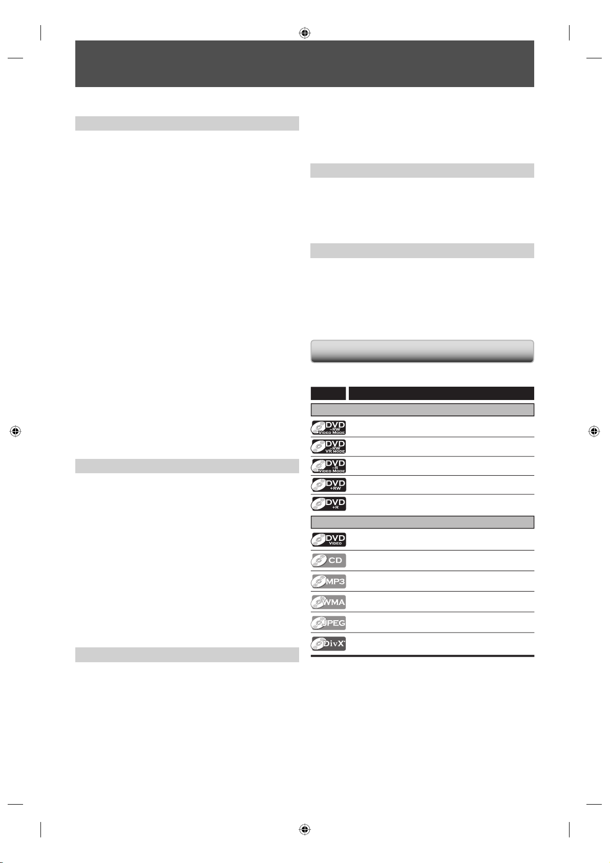
Symbols Used in this Owner’s Manual
To specify for what disc type each function is, we put the
following symbols at the beginning of each item to operate.
Symbol
For Recording, Playing Back, and Editing
Description
Description refers to DVD-RW in video mode
Description refers to DVD-RW in VR mode
Playback
Theater surround sound in your home:
When connecting the unit to an amplifier or a decoder which
is compatible with Dolby Digital or DTS, you can experience
the theater surround sound from discs with surround sound
system.
Quick search for what you want to watch:
You can easily find the part you want to watch using the
search function. Search for a desired point on a disc by title,
chapter/track or time.
Virtual surround system:
You can enjoy stereophonic space through your existing 2
channel stereo system.
Playing back on MP3/WMA/JPEG/DivX® files:
You can enjoy MP3/WMA/JPEG/DivX® files which are recorded on CD-RW/-R.
DivX® files can also be recorded on DVD-RW/-R and
DVD+RW/+R.
Editing
Deleting titles:
You can delete titles which you do not need anymore.
Setting or clearing chapter marks:
You can set or clear chapter marks on titles.
Hiding chapters:
To keep others from playing back some chapters without
permission, you can hide chapters.
Deleting parts of titles:
You can delete a specific part of a title.
Description refers to DVD-R in video mode
Description refers to DVD+RW
Description refers to DVD+R
For Playback only
Description refers to DVD-video
Description refers to audio CD
Description refers to CD-RW/-R with MP3 les
Description refers to CD-RW/-R with WMA les
Description refers to CD-RW/-R with JPEG les
Description refers to DVD-RW/-R, DVD+RW/+R
and CD-RW/-R with DivX® les
If you do not nd any of the symbols listed above under
the function heading, the operation is applicable to all
media.
8EN8EN
E7M70UD_D-R560KU_EN.indd 8E7M70UD_D-R560KU_EN.indd 8 2007/12/17 11:11:232007/12/17 11:11:23
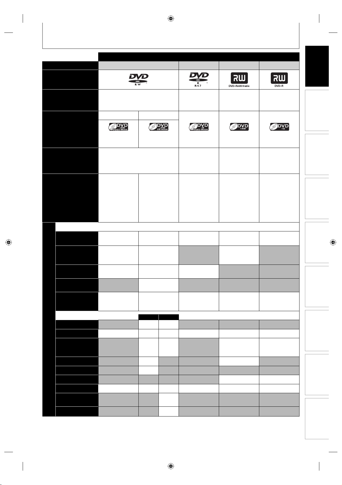
FEATURES
Discs for Recording, Playing back
Disc type DVD-RW DVD-R DVD+RW DVD+R
Logo
Introduction
Format
Maximum record
Recordable/playable
Recording Features
Record TV
programs
Reuse by deleting
the current
contents
Record 16:9 size
pictures
Record copy-once
programs
Create chapters
at fixed intervals
(auto chapter)
Editing Features
Scene delete
Available Features
Edit title name
Create chapters
wherever you like
(chapter mark)
Divide a title
Combine titles
Hide chapters
Delete a title
Create a
playlist
Protect a title
versions
Compatibility
Can be formatted in VR or video
mode
Video Mode VR Mode
Icon
480 min (12cm)
time
144 min (8cm)
Ver.1.1,1.2
Ver.1.1/2× CPRM compatible
Ver.1.2/4× CPRM compatible
Playable on
most DVD
players.
Finalization
necessary.
(title menu will
be created)
✓✓✓✓✓
✓✓ ✓
✓✓✓
✓✓✓✓✓
✓✓✓✓✓✓
✓✓✓✓✓✓
Automatically
formatted in
video mode
480 min (12cm)
144 min (8cm)
Playable only
on VR mode
compatible unit.
Finalization
recommended.
✓*
Playlist
Original
✓✓
✓✓ ✓ ✓
✓✓
✓
480 min (12cm)
144 min (8cm)
Ver.2.0
Ver.2.0/4×
Ver.2.0/8×
Ver2.0/16×
Playable on
most DVD
players.
Finalization
necessary.
(title menu will
be created)
✓
✓
Automatically
formatted in
+VR mode
480 min (12cm)
144 min (8cm)
1×-4× 1×-16×
Playable on
DVD+RW
compatible
players.
Finalization
recommended.
(title menu will
be created)
✓✓
Automatically
formatted in
+VR mode
480 min (12cm)
144 min (8cm)
Playable on
most DVD
players.
Finalization
recommended.
(title menu will
be created)
Connections Basic Setup
Management
Recording
Playback
Editing Function Setup
Others
Disc
✓: Available Gray: Not available
*CPRM compatible disc only.
9EN 9EN
E7M70UD_D-R560KU_EN.indd 9E7M70UD_D-R560KU_EN.indd 9 2007/12/17 11:11:232007/12/17 11:11:23
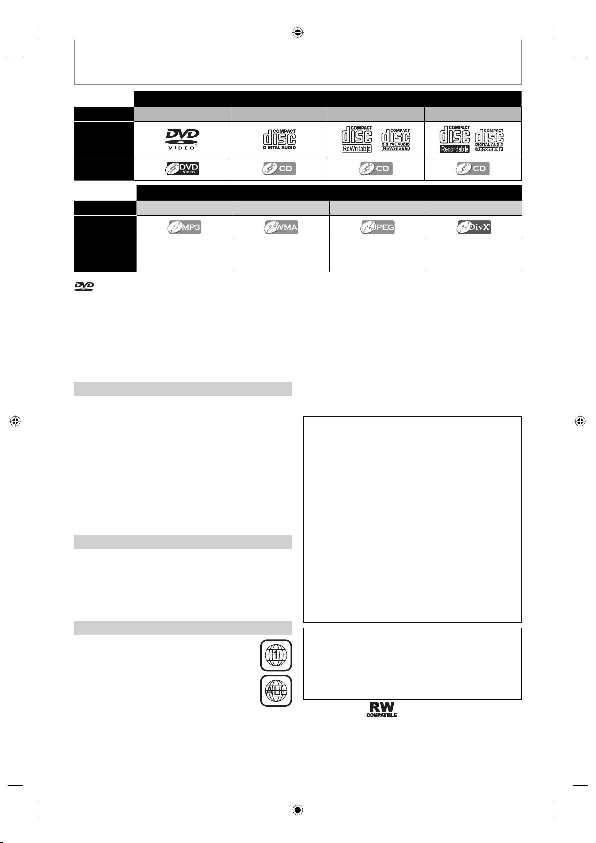
FEATURES
Discs for playing back
Disc Type DVD-VIDEO CD-DA CD-RW CD-R
Logo
Icon
Files for playing back
Type of title MP3 WMA JPEG DivX®
Icon
Media CD-RW/-R CD-RW/-R CD-RW/-R
is a trademark of DVD Format/Logo Licensing Corporation.
• Official DivX® Certified product
• Plays all versions of DivX® video (including DivX® 6) with
standard playback of DivX® media files
• Discs containing the DivX® files with the DivX® GMC (Global
Motion Compensation) playback feature, which is DivX®
supplemental function, cannot be played back on this unit.
* This unit cannot play back the disc contents protected
by Windows Media Digital Rights Management (DRM).
Unplayable Discs
The following discs will not play back on this unit.
• CD-ROM • Compact Disc-Interactive (CD-I)
• Video Single Disc (VSD) • DVD-ROM
• DVD-audio • Unfinalized disc
• DVD contains MP3, WMA or JPEG files
• DVD-RW/-R recorded in non compatible recording format
• Blu-ray Disc • HD DVD
On the following disc, the sound may not be heard.
• Super audio CD - Only the sound on the CD layer can be
heard. The sound on the high-density super audio CD
layer cannot be heard.
Color Systems
DVD is recorded in different color systems throughout
the world. The most common color system is NTSC
(which is used primarily in the United States and Canada).
This unit uses NTSC, so DVD you play back must be
recorded in the NTSC system. You cannot play back DVD
recorded in other color systems.
Region Codes
This unit has been designed to play back DVD
with region 1. DVD must be labeled for ALL
regions or for region 1 in order to play back on
the unit. You cannot play back DVD that are
labeled for other regions. Look for the symbols
on the right on your DVD. If these region
symbols do not appear on your DVD, you cannot
play back the DVD in this unit.
CD-RW/-R
DVD-RW/-R
DVD+RW/+R
The number inside the globe refers to region of the world.
A DVD labeled for a specific region can only play back on
the unit with the same region code.
Following discs are recommended for good recording
quality and are proven to be compatible with this unit.
However, depending on the media condition, the unit
may not read the disc properly.
Verbatim DVD+R 8x, DVD+RW 4x, DVD-R 8x, DVD-RW 2x
JVC DVD-RW 4x
Maxell DVD+R 4x/8x/16x, DVD-R 8x/16x
SONY DVD+R 4x/8x/16x, DVD+RW 4x
TDK DVD+R 4x/8x/16x
Performance of any other discs are not guaranteed.
• Toshiba is not liable for any damage or loss caused directly
or indirectly by the malfunction of this recorder, including,
without limitation, any one of the following:
• Failure to record contents intended to be recorded by
the consumer.
• Failure to edit contents as intended by the consumer.
• When a DVD-RW/-R, DVD+RW/+R disc created on this
recorder is used (e.g., insertion, playback, recording or
editing) in another DVD player, recorder or personal
computer drive.
• When a DVD-RW/-R, DVD+RW/+R disc that is used in
the manner described in the immediately preceding
bullet point is used again in this recorder.
• When a DVD-RW/-R, DVD+RW/+R disc that was
recorded in another DVD recorder, or in a personal
computer drive is used in this recorder.
• Some functions may not work with personal computer
discs.
• Discs recorded in this recorder may not operate as
expected on other DVD players, recorders or personal
computer drives.
Because of problems and errors that can occur during the
creation of DVD and CD software and/or the manufacture
of DVD and CD discs, Toshiba cannot assure that this DVD
Video Recorder will successfully play every disc bearing the
DVD and CD logos. If you happen to experience any
difficulty playing a DVD and/or CD disc on this DVD Video
Recorder, please contact Toshiba Customer Service.
DVD players with
recorded in VR mode.
are capable of playing DVD-RW
10 EN10 EN
E7M70UD_D-R560KU_EN.indd 10E7M70UD_D-R560KU_EN.indd 10 2007/12/17 11:11:252007/12/17 11:11:25
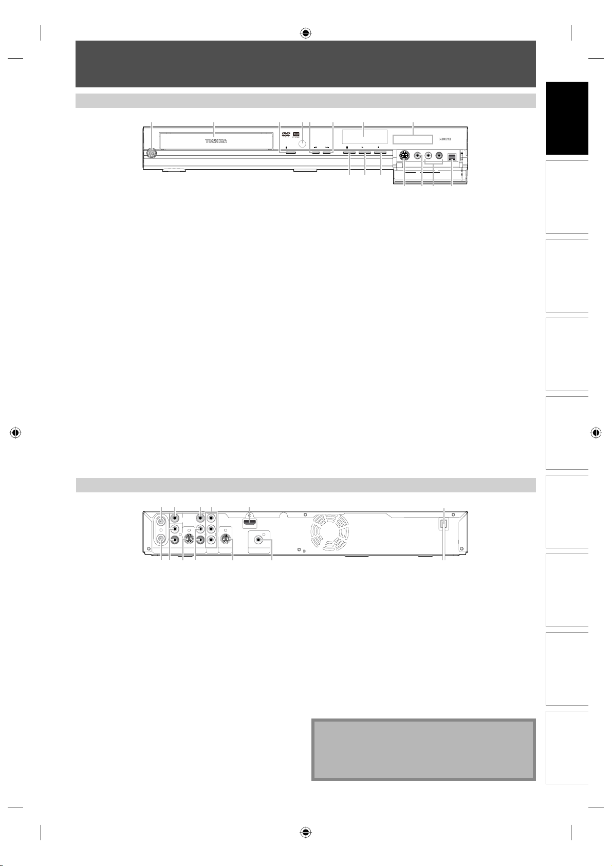
Front Panel
FUNCTIONAL OVERVIEW
12
ON/STANDBY
I/y
DVD -RW/R +RW/R RECORDING
4
3* 5 6
OPEN/CLOSE
78
1080p
1080i 720p 480p
RECPLAYSTOPSKIP
Introduction
(*) The unit can also be turned on by pressing these buttons.
1. I/y ON/STANDBY button
Press to turn the unit on and off.
If timer programmings have been set, press to set the
unit in timer-standby mode.
2. Disc tray
Place a disc when the disc tray is opened.
3. A OPEN/CLOSE button*
Press to open or close the disc tray.
4. Infrared sensor window
Receive signals from your remote control so that you
can control the unit from a distance.
5. H (SKIP) button
During playback, press once midway through a
chapter or track to go back to the beginning of the
current chapter or track. When pressed twice in quick
succession, playback will start from the preceding
chapter or track.
During playback, press and hold for 1.5 seconds to
fast reverse.
When playback is paused, press to play back reverse
step by step.
When playback is paused, press and hold for 1.5
seconds to slow reverse.
6. G (SKIP) button
During playback, press to skip to the next chapter or track.
During playback, press and hold for 1.5 seconds to
fast forward.
L2
15
14* 13
S-VIDEO VIDEO L R DV IN
9101112
When playback is paused, press to play back advance
step by step.
When playback is paused, press and hold for 1.5
seconds to slow forward.
7. Display
Refer to “FRONT PANEL DISPLAY GUIDE” on page 17.
8. HDMI indicator
Lights up and indicates the HDMI output mode when
HDMI output is on.
9. DV IN jack (L3)
Use to connect the DV output of external device with
a DV cable.
10. AUDIO input jacks (L2)
Use to connect external device with an RCA audio
cable.
11. VIDEO input jack (L2)
Use to connect external device with an RCA video
cable.
12. S-VIDEO input jack (L2)
Use to connect the S-video output of external device
with an S-video cable.
13. I REC button
Press once to start a recording. Press repeatedly to
start one-touch timer recording.
14. B PLAY button*
Press to start or resume playback.
15. C STOP button
Press to stop playback or recording.
Connections Basic Setup
Management
Disc
Recording
Rear Panel
4
32 51
IN
VIDEOINVIDEO
OUT
Y
L
L
PB/CB
R
R
PR/CR
IN OUT
ANTENNA
OUT
AUDIO IN
(L1)
S-VIDEO
AUDIO OUT
COMPONENT
VIDEO OUT
1. ANTENNA IN jack
Use to connect an antenna.
2. VIDEO IN jack (L1)
Use to connect external device with an RCA video
cable.
3. VIDEO OUT jack
Use to connect a TV monitor, AV receiver or other
device with an RCA video cable.
4. COMPONENT VIDEO OUT jacks
Use to connect a TV monitor with component video
inputs with a component video cable.
5. HDMI OUT jack
Use an HDMI cable to connect to a display with an
HDMI compatible port.
6. AC Power Cord
Connect to a standard AC outlet to supply power to
this unit.
7. COAXIAL DIGITAL AUDIO OUTPUT jack
Use to connect an AV receiver, Dolby Digital decoder,
DTS decoder or other device with a digital audio
coaxial input jack with a digital audio coaxial cable.
S-VIDEO
HDMI OUT
COAXIAL
DIGITAL AUDIO OUTPUT
PCM / BITSTREAM
8
710 91112
6
8. S-VIDEO OUT jack
Use to connect the S-video input of a TV monitor, AV
receiver or other device with an S-video cable.
9. AUDIO OUT jacks
Use to connect a TV monitor, AV receiver or other
device with an RCA audio cable.
10. S-VIDEO IN jack (L1)
Use to connect the S-video output of external device
with an S-video cable.
11. AUDIO IN jacks (L1)
Use to connect external device with an RCA audio
cable.
12. ANTENNA OUT jack
Use to connect an RF coaxial cable to pass the signal
from the ANTENNA IN to your TV.
Note
• Do not touch the inner pins of the jacks on the rear
panel. Electrostatic discharge may cause permanent
damage to the unit.
• This unit does not have the RF modulator.
Playback
Editing Function Setup
Others
11EN 11EN
E7M70UD_D-R560KU_EN.indd 11E7M70UD_D-R560KU_EN.indd 11 2007/12/17 11:11:272007/12/17 11:11:27
Remote Control
FUNCTIONAL OVERVIEW
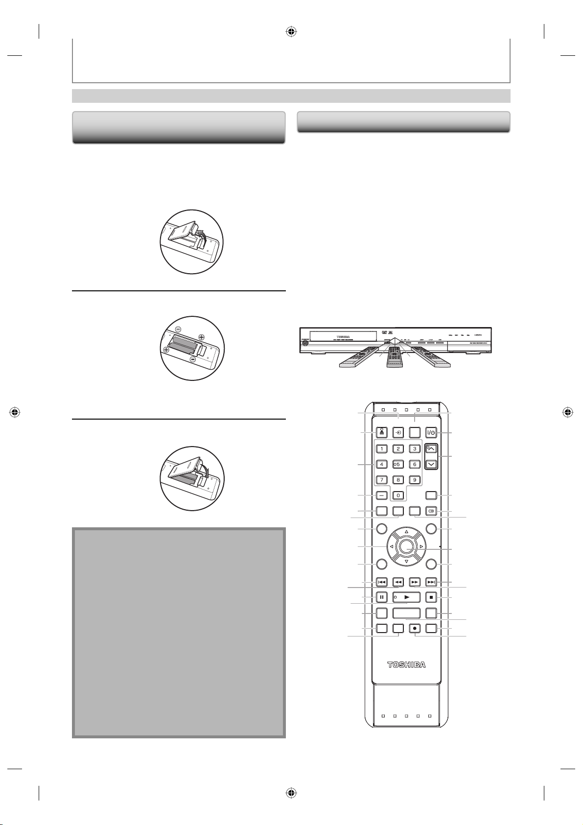
Installing the Batteries in the Remote
Control
Install the batteries (AAx2) matching the polarity
indicated inside battery compartment of the remote
control.
Open the cover.
1
Insert batteries.
2
Make sure to match + and - on the batteries to
the marks indicated in the battery compartment.
Close the cover.
3
Caution:
Never throw batteries into a fire.
Note:
• Be sure to use AA size batteries.
• Dispose of batteries in a designated disposal area.
• Batteries should always be disposed of with the
environment in mind. Always dispose of batteries in
accordance with applicable laws and regulations.
• If the remote control does not operate correctly, or if
the operating range becomes reduced, replace
batteries with new ones.
• When necessary to replace batteries in the remote
control, always replace both batteries with new ones.
Never mix battery types or use new and used
batteries in combination.
• Always remove batteries from remote control if they
are dead or if the remote control is not to be used for
an extended period of time. This will prevent battery
acid from leaking into the battery compartment.
Using a Remote Control
Keep in mind the followings when using the remote
control:
• Make sure that there are no obstacles between the remote
control and the infrared sensor window on the unit.
• Remote operation may become unreliable if strong
sunlight or fluorescent light is shining on the infrared
sensor window of the unit.
• Remote control for different devices can interfere with
each other. Avoid using remote control for other device
located close to the unit.
• Replace the batteries when you notice a fall off in the
operating range of the remote control.
• The maximum operable ranges from the unit are as
follows.
- Line of sight: approx. 23 feet (7m)
- Either side of the center:
approx. 23 feet (7m) within 30°
30˚30˚
CH
TIMER
PROG.
MENU/LIST
STOP
INSTANT SKIP
23feet (7m)
17
18
19
20
21
22
23
24
25
26
27
28
29
30
31
32
23feet (7m) 23feet (7m)
1
OPEN/
INPUT
CLOSE
SELECT
.@/: ABC
JKL MNO
GHI
PQRS TUV
SPACE
SETUP DISPLAY AUDIO
DTV/TV
TOP MENU
ENTER
CLEAR RETURN
SKIP REV
PLAY
PAUS E
1.3x / 0.8x PLAY
TIME SLIP
REC MODE ZOOMRECREPEAT
SE-R0264
11
13*
16
2*
3
4
5
6
7
8
9
10
12
14
15
HDMI
DEF
WXYZ
FWD SKIP
12 EN12 EN
E7M70UD_D-R560KU_EN.indd 12E7M70UD_D-R560KU_EN.indd 12 2007/12/17 11:11:282007/12/17 11:11:28

FUNCTIONAL OVERVIEW
I/y
(*) The unit can also be turned on by pressing these buttons.
Introduction
1. INPUT SELECT
• Press to select the appropriate input.
2. OPEN/CLOSE A button*
• Press to open or close the disc tray.
3. Number/Character buttons
• Press to select channel numbers.
• Press to select a title/chapter/track/file on display.
• Press to enter values for the settings in the main
menu.
• Press to enter title names.
4. Confirm ( − ) button
Analog mode:
• Press to confirm the channel selection made by
[the Number buttons].
Digital mode:
• Press to confirm the major / minor channel
selection made by [the Number buttons].
5. DTV/TV button
• Press to switch between digital TV (DTV) mode and
analog TV (TV) mode.
6. SETUP button
• Press to display the main menu.
• During DVD playback, press and hold for more than
3 seconds to switch the progressive scanning mode
to the interlace mode.
7. TOP MENU button
• Press to display the title list.
8. Cursor K / L / { / B buttons
• Press to select items or settings.
9. CLEAR button
• Press to clear the password once entered, to cancel
the programming for CD, to clear the selecting
marker number in the display menu, etc.
10. SKIP H button
• During playback, press to return to the beginning of
the current chapter, track or file.
• During playback, press twice in quick succession to
skip to the previous chapter or track.
• When playback is in pause, press repeatedly to
reverse the playback step by step.
11. REV E button
• During playback, press to fast reverse playback.
• When playback is in pause, press to slow reverse
playback.
12. PAUSE F button
• Press to pause playback or recording.
13. PLAY B button*
• Press to start playback or resume playback.
14. TIME SLIP button
• Press once to start recording the TV program you
are watching. Press again to watch the content
being recorded from the beginning while recording
continues. (VR mode DVD-RW with the recording
mode of LP, EP or SLP only)
15. REPEAT button
• Press to display the repeat menu.
16. REC MODE button
• Press to switch the recording mode.
button
17. HDMI button
• Press to set the HDMI connector’s video signal
output mode .
18.
ON/STANDBY button
• Press to turn the unit on and off. If timer
programmings have been set, press to set the unit in
timer-standby mode.
19. CH
• Press to change the channel up and down.
20. TIMER PROG. button
• Press to display the timer programming list.
21. AUDIO
• Press to switch the audio language for digital TV.
• Press to display the audio menu during playback.
22. DISPLAY button
• Press to display the display menu on or off.
23. MENU/LIST button
• Press to display the disc menu. To change original
24. ENTER button
• Press to confirm or select menu items.
25. RETURN
• Press to return to the previous displayed menu
26. SKIP G button
• During playback, press to skip to the next chapter,
• When playback is in pause, press repeatedly to
27. FWD D button
• During playback, press to fast forward playback.
• When playback is in pause, press to slow forward
28. STOP C button
• Press to stop playback or recording.
• Press to exit from the title list.
29. INSTANT SKIP button
• During playback, press to skip 30 seconds.
30. 1.3x/0.8x PLAY button
• During playback, press to play back in a slightly
31. ZOOM button
• During playback, press to enlarge the picture on the
32. REC I button
• Press once to start a recording.
• Press repeatedly to start the one-touch timer
/ buttons
button
and playlist on the TV screen.
button
screen.
track or file.
forward the playback step by step.
playback.
faster/slower speed while keeping the sound output.
TV screen.
recording.
Connections Basic Setup
Management
Disc
Recording
Playback
Editing Function Setup
Others
13EN 13EN
E7M70UD_D-R560KU_EN.indd 13E7M70UD_D-R560KU_EN.indd 13 2007/12/19 13:47:422007/12/19 13:47:42
GUIDE TO ON-SCREEN DISPLAYS AND MENUS
This unit uses the following on-screen displays and menus to guide you to the easy operations.
The on-screen displays give you the information on the loaded disc, the disc/file in playback, or the HDMI status, etc.
The menus allow you to change the various kinds of settings for playing back, recording, or editing to suit your preference.
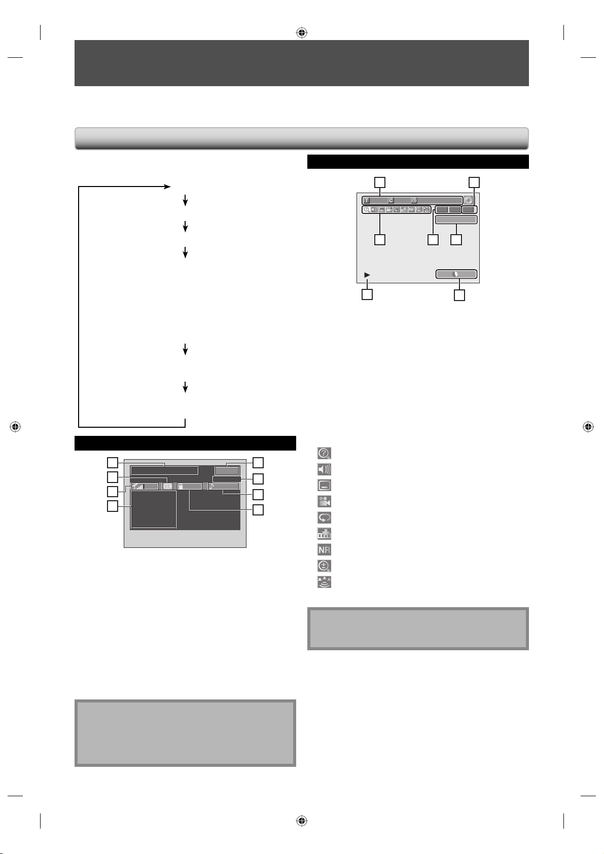
On-Screen Display / Menu
The on-screen display changes in the following order
as you press [DISPLAY].
OFF
DTV Program Guide (only in DTV mode)
Disc Information/Menu
Title Name Information
(only when DVD+RW/+R, VR mode DVD-RW/-R, or
unfinalized Video mode DVD-RW/-R is in playback)
or
File Name Information
(only when a CD with MP3/WMA/
JPEG/DivX® files is in playback)
MP3/WMA Tag Information
(only when a MP3 or WMA file is in playback)
HDMI Information
(only for the images output through the HDMI output)
DTV Program Guide
1
PROGRAM TITLE NAME
2
3
INFORMATION-1
INFORMATION-2
INFORMATION-3
4
INFORMATION-4
INFORMATION-5
INFORMATION-6
90 TV-PG ENGLISH
123-45
WLIW-DT
1. Program title (max. 2 lines displayed)
2. Closed Caption (Indicates that the program being
broadcast is available with closed captioning.)
3. Signal strength (Indicates the signal strength of the
current channel.)
4. Program guide (max. 6 lines displayed)
5. Channel number
6. Broadcast station
7. Audio language (“Other” is displayed when the
audio language cannot be acquired, or the acquired
languages are other than English, Spanish or French.)
8. Program rating
5
6
7
8
Disc Information / Menu
25
1/ 5 1/ 5
0:01:00 / 1:23:45
-
RW VR ORG
CH 10
613
SP 1:53
474
* This is an example screen only
for explanation.
1. Indicates a disc type and format mode.
2. Indicates a type of titles for VR mode DVD-RW .
3. Indicates a channel number or selected external input
mode.
4. Indicates a recording mode and possible recording
time left.
5. Indicates a title number, chapter number, elapsed time
and total time of disc playback.
6. Each icon means:
: Search
: Audio
: Subtitle
: Angle
: Repeat
: Marker
: Noise Reduction / Black Level
: Zoom
: Surround
7. Indicates an operation status.
Note
• In some descriptions on this manual, only one disc
type is indicated as an example.
Note
• When the program guide is displayed in more than 7
lines, use [K / L] to scroll.
• “No description provided.” is displayed when the
program guide is not provided.
14 EN14 EN
E7M70UD_D-R560KU_EN.indd 14E7M70UD_D-R560KU_EN.indd 14 2007/12/17 11:11:302007/12/17 11:11:30
GUIDE TO ON-SCREEN DISPLAYS AND MENUS
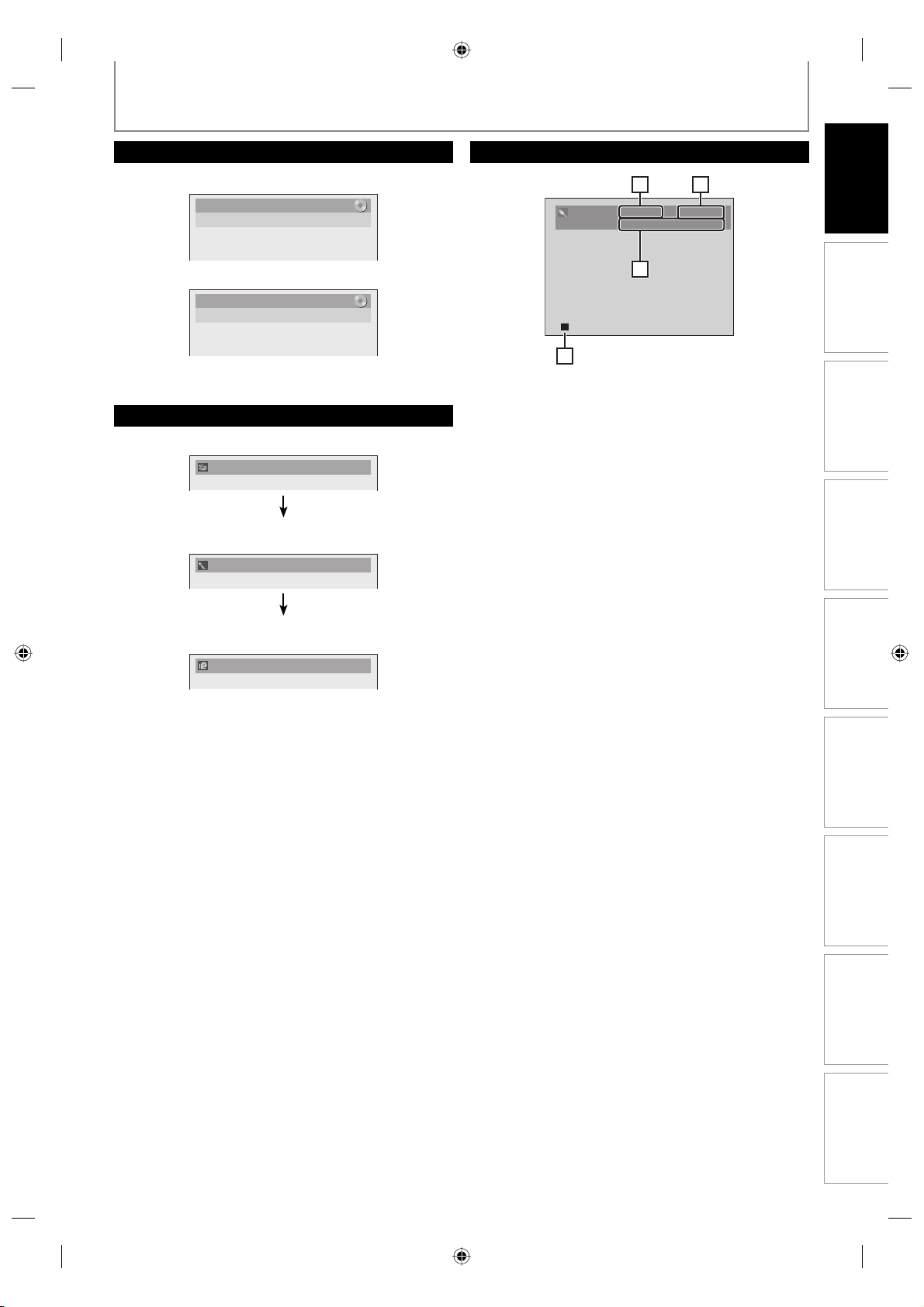
Title/File Name Information
HDMI Information
Introduction
Title name information
Title Name
My Title
File name information
File Name
My File
MP3/WMA Tag Information
• First, track name will be displayed.
Track Name
• If you press [DISPLAY] one more time, artist name will
be displayed.
Artist Name
• If you press [DISPLAY] one more time, album name
will be displayed.
Album Name
21
Video Info. : 480p / YCbCr
Audio Info. : Bitstream
343
*1. Indicates the resolution of the HDMI output image.
*2. Indicates the HDMI video format.
*3. Indicates the HDMI audio format.
4. Indicates current disc status.
* “- - -” will be displayed, when it does not have any
information.
Connections Basic Setup
Management
Disc
Recording
• If there is no artist, track or album name, “Not Available”
will be displayed.
Playback
Editing Function Setup
Others
15EN 15EN
E7M70UD_D-R560KU_EN.indd 15E7M70UD_D-R560KU_EN.indd 15 2007/12/17 11:11:302007/12/17 11:11:30
GUIDE TO ON-SCREEN DISPLAYS AND MENUS
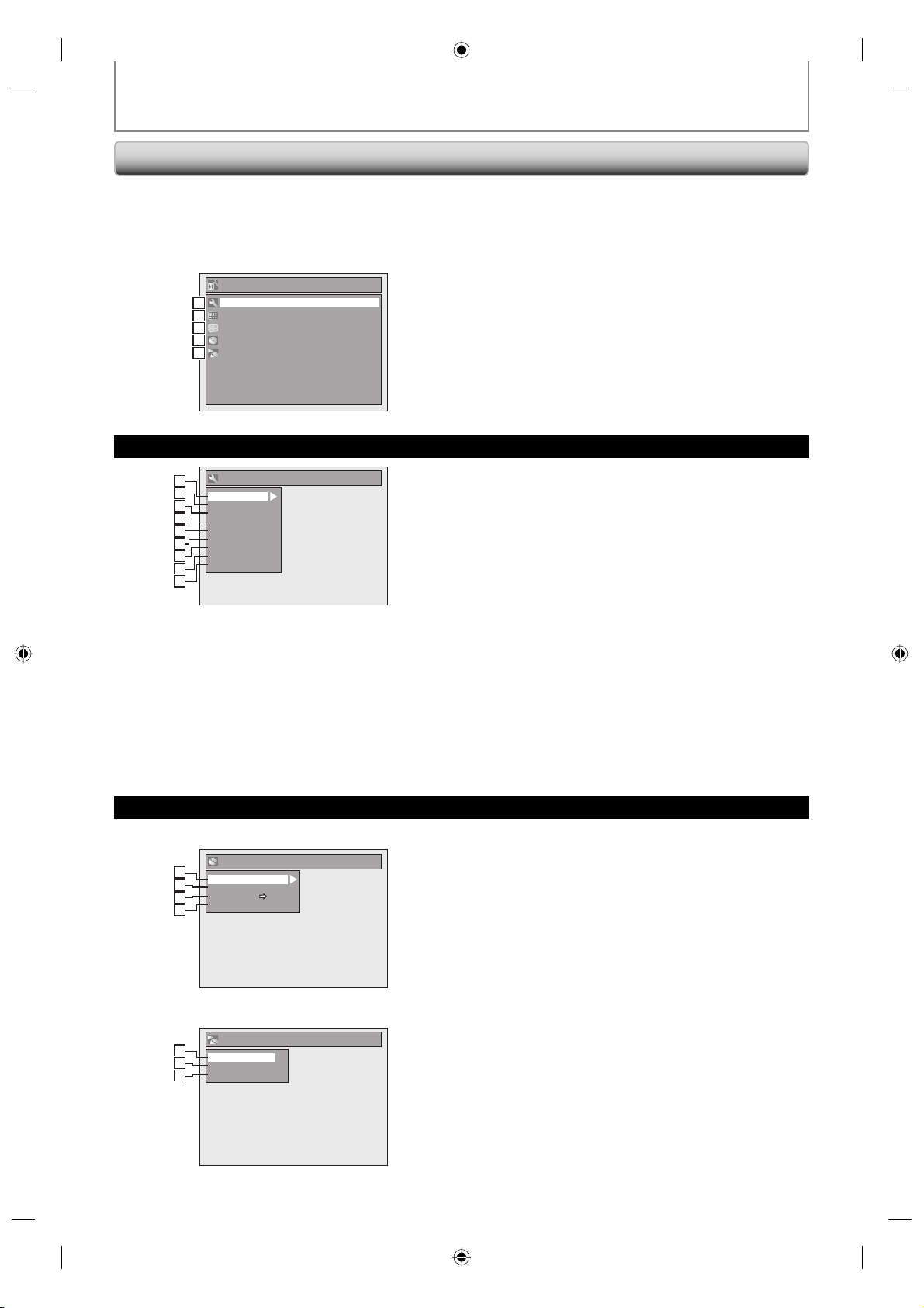
Main Menu
Press [SETUP] to display the main menu. Then use
[K / L] to select a menu and press [ENTER] to display the
menu. These menus provide entries to all main functions
of the unit.
Setup
General Setting
1
1
Timer Programming
2
2
Title List
3
3
DVD Menu
4
4
CD Playback Mode
5
5
General Setting Menu
General Setting
1
1
2
2
Playback
Display
3
3
Video
4
4
Recording
Clock
5
5
Channel
2
6
DivX
HDMI
3
7
Reset All
8
4
9
5
1. General Setting:
To go to general setting menu.
2. Timer Programming:
To program a timer recording.
3. Title List:
To call up the title list.
4. DVD Menu:
To set up the DVD setting.
5. CD Playback Mode:
To set up the CD playback setting.
• “CD Playback Mode” is available only when an audio
CD, a CD-RW/-R with MP3 / WMA / JPEG files is
inserted into the unit.
1. Playback:
To set up the unit to play back discs as you prefer.
2. Display:
To set up the OSD screen as you prefer.
3. Video:
To set up the video setting.
4. Recording:
To set up the unit to record to discs as you prefer.
5. Clock:
To set up the clock of the unit as you need.
6. Channel:
To adjust the channel setting of the unit as you prefer.
7. DivX:
To set up the setting for the DivX® playback.
8. HDMI:
To set up the HDMI connection setting.
9. Reset All:
To reset the setting to the factory default.
DVD Menu / CD Playback Mode
<DVD Menu menu>
DVD Menu
1
1
Format
2
2
Finalize
Disc Protect OFF ON
3
3
Delete All Playlists
4
4
<CD Playback Mode menu>
CD Playback Mode
1
5
Random Play
6
2
Program Play
Slide Show
7
3
1. Format (DVD-RW, DVD+RW only):
Allows you to format the disc.
2. Finalize:
Allows you to finalize a disc containing recorded titles.
3. Disc Protect (VR mode DVD-RW, DVD+RW/+R only):
Allows you to protect a disc from accidental editing or
recording.
4. Delete All Playlists (VR mode DVD-RW only):
Allows you to delete playlist.
5. Random Play:
Allows you to activate the random playback feature.
6. Program Play: (Audio CD only)
Allows you to activate the program playback feature.
7. Slide Show: (JPEG files only)
Allows you to select the display time of the slide show
mode.
16 EN16 EN
E7M70UD_D-R560KU_EN.indd 16E7M70UD_D-R560KU_EN.indd 16 2007/12/17 11:11:312007/12/17 11:11:31
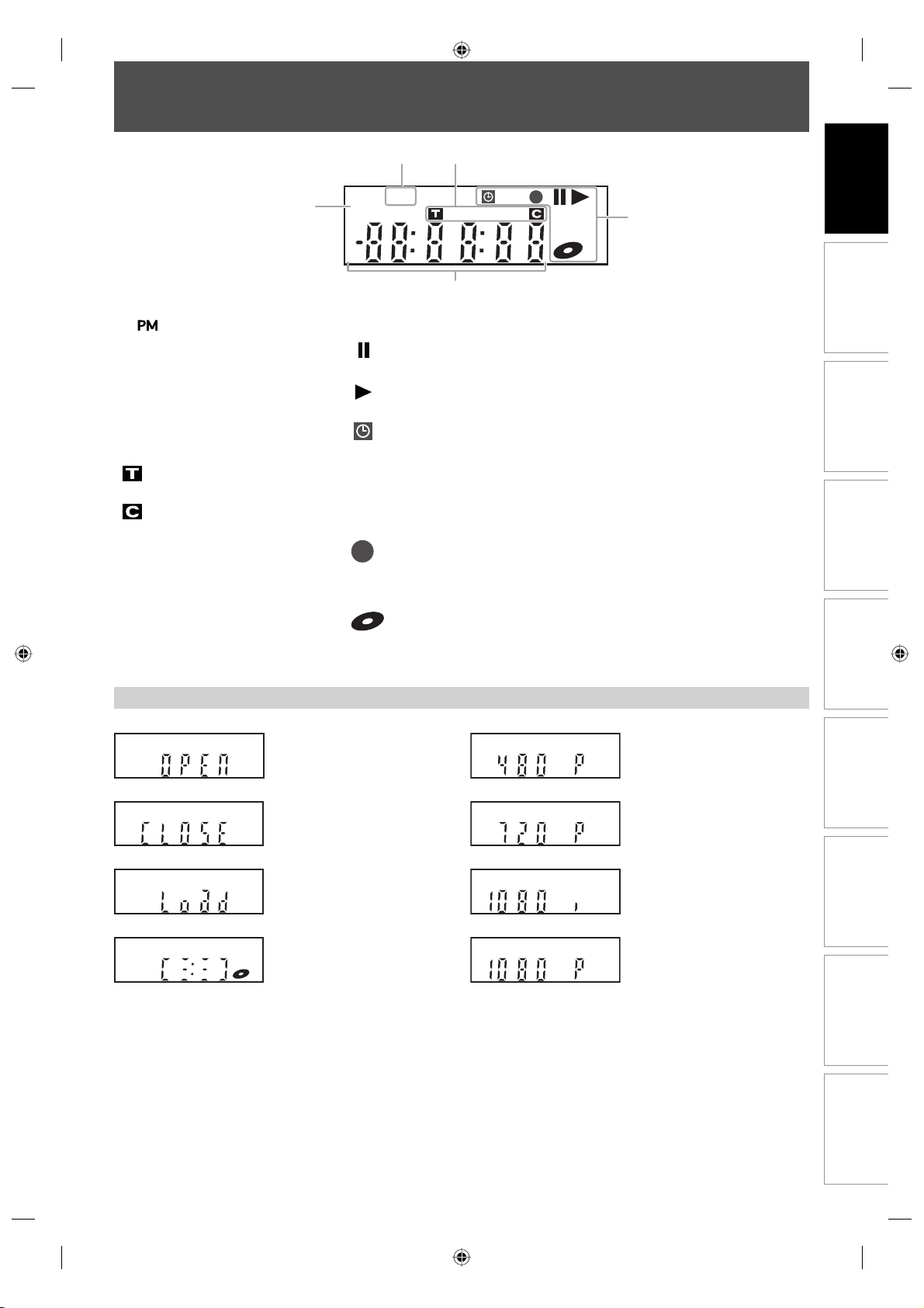
FRONT PANEL DISPLAY GUIDE
2 3
DTV
1
PM
4
5
Introduction
Connections Basic Setup
1.
: Appears in the afternoon
with the clock display.
2. DTV
: Appears when the channel
is in DTV mode.
3. Title/Track and chapter mark
: Appears when indicating a
title/track number.
: Appears when indicating a
chapter number.
Display Message
Appears when the disc tray is
opening.
4. Current status of the unit
: Appears when playback is
paused.
: Appears when playing
back a disc.
: Appears when the timer
programming or OTR has
been set and is
proceeding.
: Flashes when all timer
recordings have been
finished.
: Appears during recording
process.
: Flashes when a recording
pauses.
: Appears when a disc is in
this unit.
5. Displays the following
• Elapsed playback time
• Current title / chapter / track
number
• Recording time / remaining time
• Clock
• Channel number
• Remaining time for one-touch
timer recording
• Selected HDMI output mode
Appears when HDMI output
mode (480p) is selected.
Management
Disc
Recording
Playback
Appears when the disc tray is
closing.
Appears when a disc is loaded
on the disc tray.
Appears when data is being
recorded on a disc.
Appears when HDMI output
mode (720p) is selected.
Appears when HDMI output
mode (1080i) is selected.
Appears when HDMI output
mode (1080p) is selected.
Editing Function Setup
Others
17EN 17EN
E7M70UD_D-R560KU_EN.indd 17E7M70UD_D-R560KU_EN.indd 17 2007/12/17 11:11:322007/12/17 11:11:32
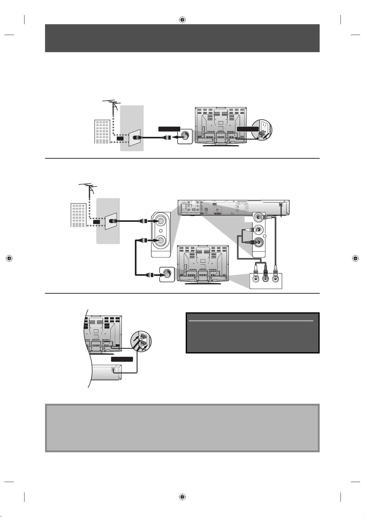
ANTENNA CABLE CONNECTION
L
O
T
This section describes how to connect your unit to an antenna, cable box, etc.
Disconnect the power cord of your TV from the AC outlet.
1
Disconnect RF coaxial cable from antenna input jack of your TV.
2
VHF / UHF
antenna
or
cable TV
company
Connect cables to the unit.
Make the basic connection as illustrated below.
3
VHF / UHF
antenna
RF coaxial cable
or
cable TV
company
RF coaxial cable
OUT
ANTENNA
RF coaxial cable
ANT. IN
IN
VIDEOINVIDEO
OUT
Y
LRL
PB/CB
R
PR/CR
IN
OUT
COMPONENT
AUDIO IN
S-VIDEO
ANTENNA
AUDIO OUT
VIDEO OUT
IN
(L1)
rear of your TV
DIGITAL AUDIO OUTPUT
PCM / BITSTREAM
rear of your TV
1112
disconnectdisconnect
VIDEO
OUT
RCA audio
cable
rear of this unit
L
R
AUDIO OUT
RCA video
cable
ANT. IN
R
AUDIO INLVIDEO IN
Plug in the power cord of this unit and your TV to the AC outlet.
4
OUTPUT
REAM
HDMI OUT
rear of your TV
connect
rear of this unit
Supplied cables used in this connection are as follows:
• RF coaxial cable x 1
• RCA audio cable (L/R) x 1
• RCA video cable x 1
Please purchase the rest of the necessary cables at your
local store.
* Once connections are completed, turn on the TV and
initial setting begins.
Channel scanning is necessary for the unit to memorize
all available channels in your area.
(Refer to “INITIAL SETTING” on page 25.)
Note
• For your safety and to avoid damage to the device, please unplug the RF coaxial cable from the ANTENNA IN jack
before moving the unit.
• If you use an antenna to receive analog TV, it should also work for DTV reception. Outdoor or attic antennas will be
more effective than set-top versions.
• RF output is for tuner pass through only. DVD playback through the RF is not possible.
18 EN18 EN
E7M70UD_D-R560KU_EN.indd 18E7M70UD_D-R560KU_EN.indd 18 2007/12/17 11:11:342007/12/17 11:11:34
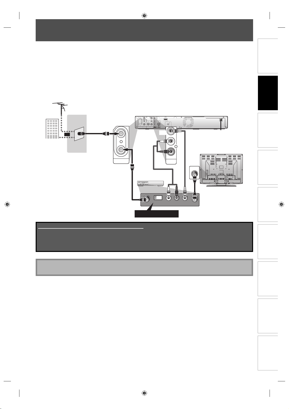
RF MODULATOR CONNECTION
If your TV has antenna in jack only, it is still possible to connect this unit to your TV by using a stereo audio/video RF
modulator. In this case, follow the instructions below.
1) Disconnect the power cords of the devices from the AC outlet.
2) Make the connection as illustrated below.
3) Set your RF modulator’s channel 3/4 switch to either 3 or 4, whichever the TV channel is least used in your area.
If your RF modulator has a Modulator/Antenna switch, set it according to the manual supplied with the RF
modulator.
4) Plug in the power cords of the devices to the AC outlet.
5) Turn on your TV and choose the same channel as you set the RF modulator’s channel 3/4 switch.
For more details, follow the manual supplied with the RF modulator.
VHF / UHF
antenna
cable TV
company
IN
VIDEOINVIDEO
OUT
Y
LRL
IN OUT
OUT
AUDIO IN
S-VIDEO
ANTENNA
RF coaxial cable
IN
(L1)
or
OUT
ANTENNA
HDMI OUT
PB/CB
R
PR/CR
COAXIAL
COMPONENT
DIGITAL AUDIO OUTPUT
S-VIDEO
AUDIO OUT
VIDEO OUT
PCM / BITSTREAM
VIDEO
OUT
AUDIO OUT
RCA video
cable
L
R
RCA audio cable
rear of your
RF modulator
rear of this unit
rear of your TV
ANT. IN
Connections
Basic Setup
Management
Disc
RF coaxial cable
43
LR
CHANNEL
AUDIO IN TO TVANT. IN
VIDEO IN
Set channel 3 or 4
Supplied cables used in this connection are as follows:
• RF coaxial cable x 1
• RCA audio cable (L/R) x 1
• RCA video cable x 1
Please purchase the rest of the necessary cables at your local store.
Note
• The quality of picture may become poor if this unit is connected to an RF modulator.
RF coaxial cable
Recording
PlaybackIntroduction
Editing Function Setup
Others
19EN 19EN
E7M70UD_D-R560KU_EN.indd 19E7M70UD_D-R560KU_EN.indd 19 2007/12/17 11:11:352007/12/17 11:11:35
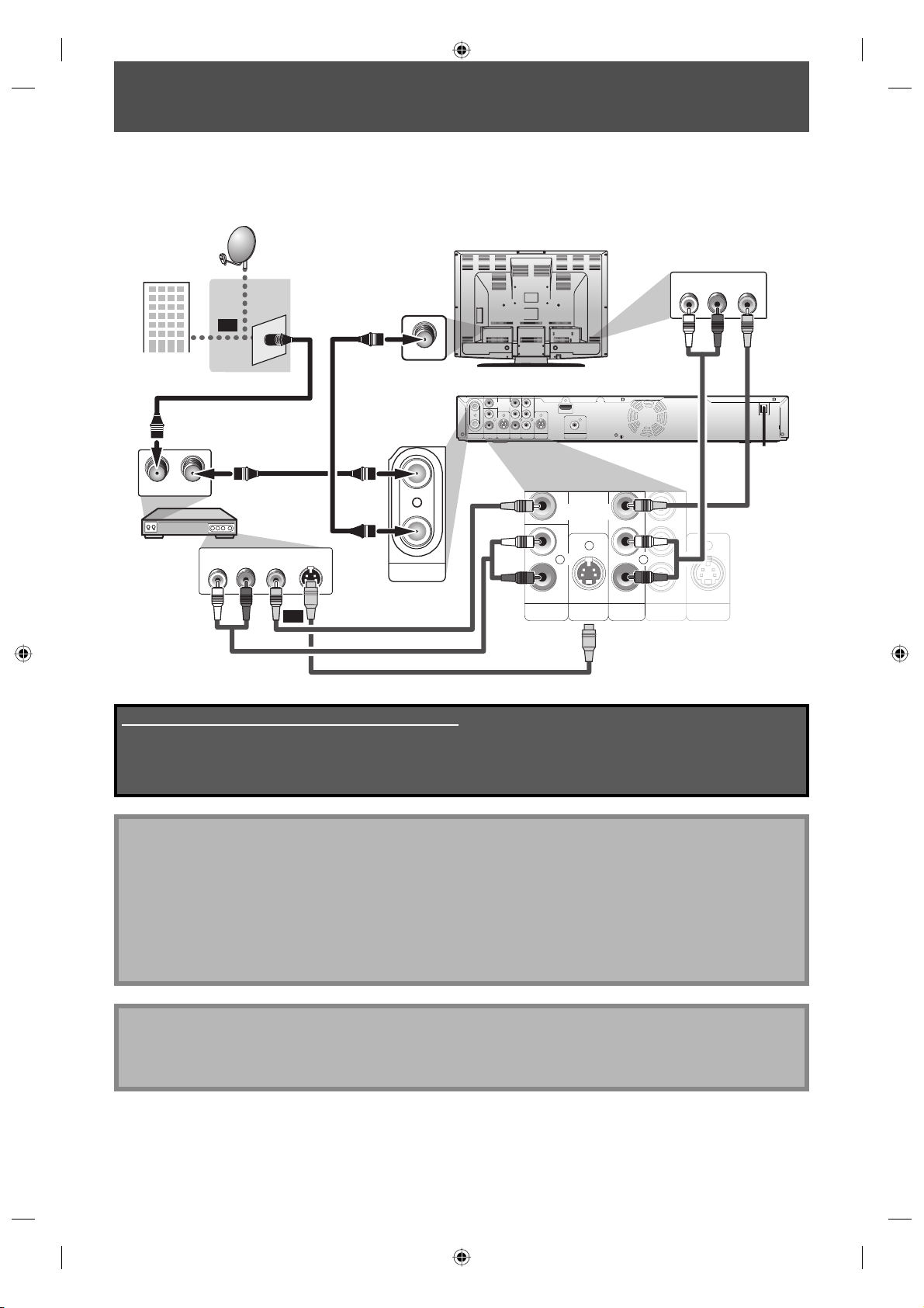
CONNECTION TO A CABLE / SATELLITE BOX
1) Disconnect the power cords of the devices from the AC outlet.
2) Make the connection as illustrated below.
3) Plug in the power cords of the devices to the AC outlet.
e.g.)
satellite
dish
or
rear of your TV
AUDIO IN
L
R
VIDEO IN
cable TV
ANT. IN
company
IN
VIDEOINVIDEO
ANTENNA
LRL
OUT
AUDIO IN
S-VIDEO
(L1)
RF OUTANT. IN
cable/satellite
box
RF coaxial cable
RF coaxial cable
AUDIO OUT
VIDEO OUT
L
R
or
S-VIDEO
OUT
IN
OUT
ANTENNA
RCA video cable
RCA audio cable
Supplied cables used in this connection are as follows:
• RF coaxial cable x 1
• RCA audio cable (L/R) x 1
• RCA video cable x 1
Please purchase the rest of the necessary cables at your local store.
OUT
Y
PB/CB
R
PR/CR
IN OUT
COMPONENT
S-VIDEO
AUDIO OUT
VIDEO OUT
AUDIO IN
(L1)
S-video cable
RCA audio
HDMI OUT
COAXIAL
DIGITAL AUDIO OUTPUT
PCM / BITSTREAM
VIDEOINVIDEO
OUT
L
R
IN OUT
S-VIDEO
L
R
AUDIO OUT
COMPONENT
VIDEO OUT
Y
PB/CB
PR/CR
cable
S-VIDEO
RCA video
cable
Note
• Required cables and connecting methods differ depending on the cable/satellite box.
For more information, please contact your cable/satellite provider.
• Instead of using VIDEO OUT jack of this unit, you can also use S-VIDEO OUT jack, COMPONENT VIDEO OUT jack, or
HDMI OUT jack (no AUDIO OUT jack connection required) for connecting to your TV.
With this setup:
• You can record any unscrambled channel by selecting the channel on the cable/satellite box. Be sure that the
cable/satellite box is turned on.
• You cannot record one channel while watching another channel.
Note to CATV system installer
• This reminder is provided to call the cable TV system installer’s attention to Article 820-40 of the National Electrical
Code, which provides guidelines for proper grounding - in particular, specifying that the cable ground shall be
connected to the grounding system of the building, as close to the point of cable entry as possible.
20 EN20 EN
E7M70UD_D-R560KU_EN.indd 20E7M70UD_D-R560KU_EN.indd 20 2007/12/17 11:11:362007/12/17 11:11:36
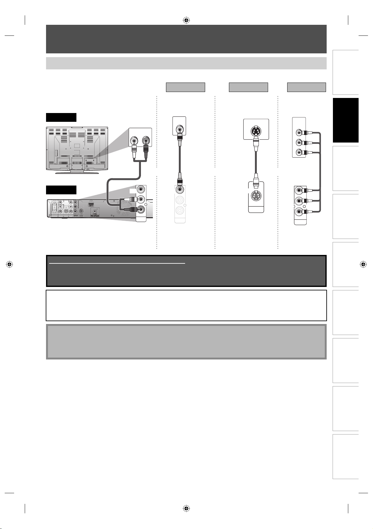
CONNECTION TO A TV
Make one of the following connections, depending on the capabilities of your display device.
Method 1
standard picture
VIDEO
IN
TV
analog audio
rear of your TV
AUDIO IN
RL
RCA
video cable
VIDEO
OUT
L
R
AUDIO OUT
VIDEO OUT
this unit
IN
VIDEOINVIDEO
LRL
IN
OUT
AUDIO IN
S-VIDEO
ANTENNA
(L1)
RCA
audio cable
VIDEO
OUT
OUT
AUDIO OUT
HDMI OUT
R
COAXIAL
DIGITAL AUDIO OUTPUT
PCM / BITSTREAM
and or or
L
R
AUDIO OUT
AUDIO OUT
Supplied cables used in this connection are as follows:
• RCA audio cable (L/R) x 1
• RCA video cable x 1
Please purchase the rest of the necessary cables at your local store.
Method 2 Method 3
good picture better picture
COMPONENT
S-VIDEO IN
VIDEO IN
PB/CB
PR/CR
S-video cable
component
video cable
Y
OUT
S-VIDEO
PB/CB
PR/CR
COMPONENT
VIDEO OUT
S-VIDEO OUT COMPONENT
VIDEO OUT
Connections
Y
Basic Setup
Management
Disc
Recording
After you have completed the connections
• Switch the input selector on your TV to an appropriate external input channel. Press a button on the TV’s original
remote control that selects an external input channel until the DVD recorder’s opening picture appears. Check your
TV owner’s manual for details.
Note
• Connect this unit directly to the TV. If the RCA audio/video cables are connected to a VCR, pictures may be
distorted due to the copy protection system.
• Progressive signal does not output from the VIDEO OUT or S-VIDEO OUT jack.
To set progressive scan mode, refer to page 103
• This unit is compatible with the progressive scan system. The feature provides you the higher quality images than the
traditional output system. To utilize this feature, you must set “Progressive” to “ON”.
PlaybackIntroduction
Editing Function Setup
Others
21EN 21EN
E7M70UD_D-R560KU_EN.indd 21E7M70UD_D-R560KU_EN.indd 21 2007/12/17 11:11:362007/12/17 11:11:36
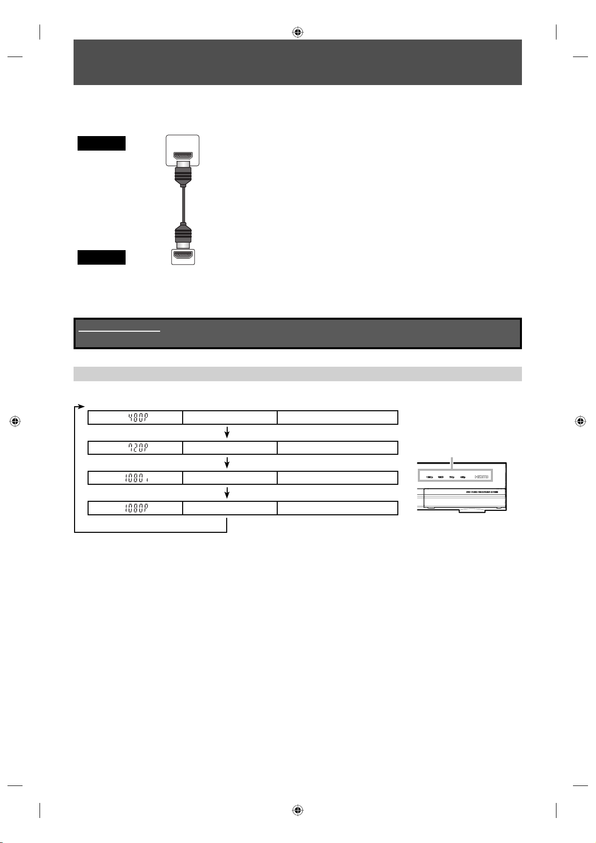
CONNECTION TO A TV WITH AN HDMI™ COMPATIBLE PORT
A simple 1-cable connection with a device having an HDMI (high-definition multimedia interface) connector allows
digital transfer of both digital video signals and multi-channel audio signals.
TV
this unit
When connecting with an HDMI cable, the audio signal will be output as the digital audio signal simultaneously, so
you do not need the analog audio connection described on page 21.
Cables not included.
Please purchase the necessary cables at your local store.
HDMI IN
HDMI cable
HDMI OUT
HDMI Mode and Actual Output Signals
Press [HDMI] to select the HDMI output mode. The output mode changes as follows every time [HDMI] is pressed.
Front Panel Display HDMI Indicator Video Output Signal
480p 480 Progressive
Press [HDMI]
Press [HDMI]
720p 720 Progressive
HDMI indicator
1080i 1080 interlaced
Press [HDMI]
1080p 1080 Progressive
Press [HDMI]
• The HDMI mode that is not supported by display device will be skipped.
22 EN22 EN
E7M70UD_D-R560KU_EN.indd 22E7M70UD_D-R560KU_EN.indd 22 2007/12/17 11:11:372007/12/17 11:11:37
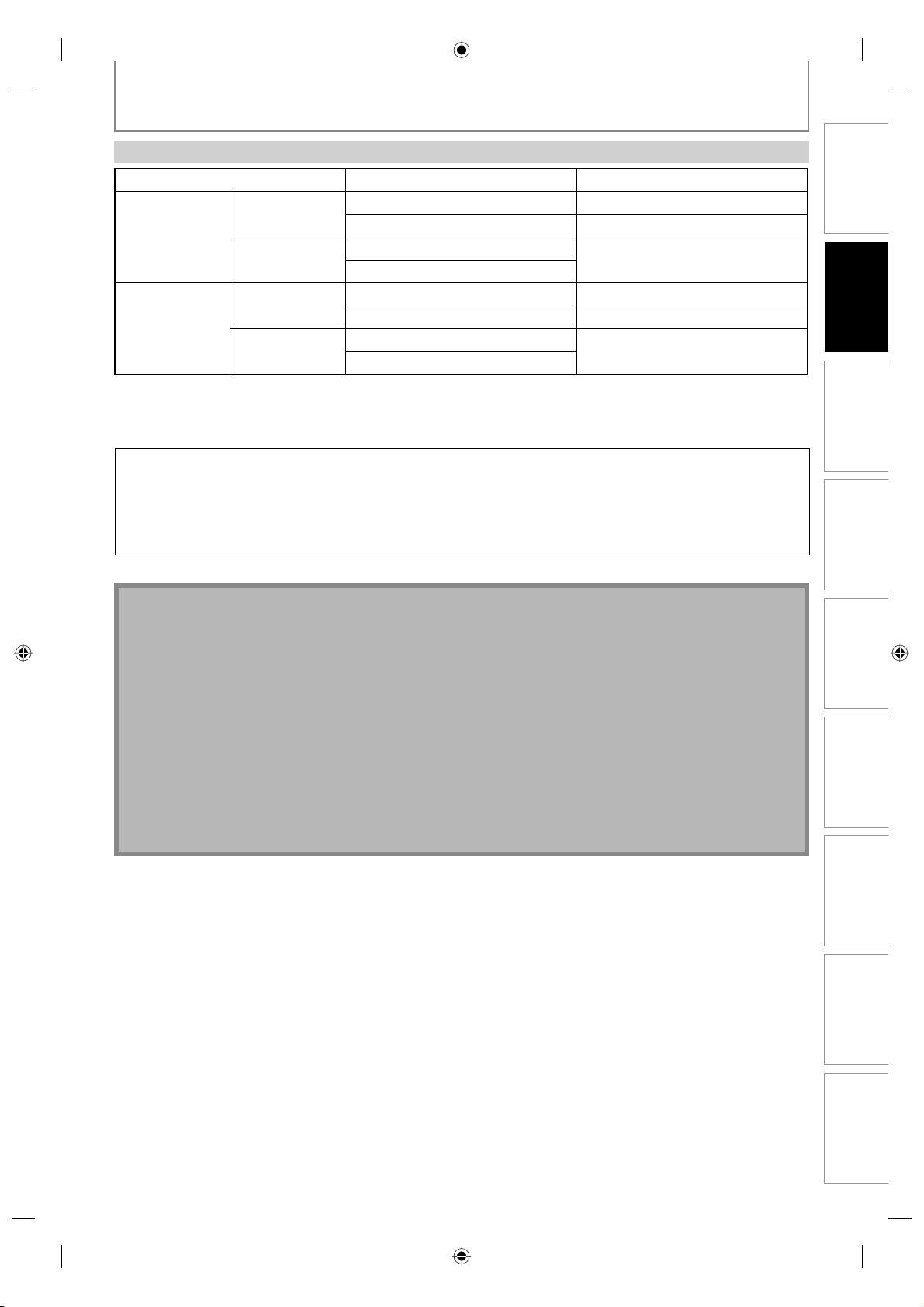
CONNECTION TO A TV WITH AN HDMI™ COMPATIBLE PORT
Actual Output Modes by Media
Audio recording format of the disc Dolby Digital setting of this unit Actual output
Dolby Digital
DVD-video
LPCM
Dolby Digital
DivX®
MP3 / MP2
For audio CD and MP3 / WMA files, 2 channel PCM will be output regardless of the “Dolby Digital” setting.
If the connected device is not compatible with HDMI BITSTREAM, audio will be output as PCM even if you select
“Stream” in “Dolby Digital” setting (Refer to page 98).
Copyright protection system
To play back the digital video images of a DVD via an HDMI connection, it is necessary that both the player and the
display device (or an AV amplifier) support a copyright protection system called HDCP (high-bandwidth digital
content protection system). HDCP is copy protection technology that comprises data encryption and authentication
of the connected AV device. This unit supports HDCP. Please read the operating instructions of your display device
(or AV amplifier) for more information.
*HDMI: High Definition Multimedia Interface
PCM 2channel PCM
Stream Dolby Digital
PCM
Stream
PCM 2channel PCM
Stream Dolby Digital
PCM
Stream
2channel PCM
2channel PCM
Connections
Basic Setup
Management
Disc
Note
• Because HDMI is an evolving technology, it is possible that some devices with an HDMI input may not operate
properly with this unit.
• When using an HDCP-incompatible display device, the image will not be viewed properly.
• Among the devices that support HDMI, some devices can control other devices via the HDMI connector; however,
this unit cannot be controlled by another device via the HDMI connector.
• The audio signals from the HDMI connector (including the sampling frequency, the number of channels and bit
length) maybe limited by the device that is connected.
• Among the monitors that support HDMI, some do not support audio output (for example, projectors). In
connections with device such as this unit, audio signals are not output from the HDMI output connector.
• When this unit’s HDMI connector is connected to a DVI-D compatible monitor (HDCP compatible) with an HDMIDVI converter cable, the signals are output in digital RGB.
• If the connected equipment is not compatible with HDMI BITSTREAM, DTS sound will not be output.
• When the power failure occurs, or when you unplug the unit, some problems in the HDMI setting might occur.
Please check and set the HDMI setting again.
Recording
PlaybackIntroduction
Editing Function Setup
Others
23EN 23EN
E7M70UD_D-R560KU_EN.indd 23E7M70UD_D-R560KU_EN.indd 23 2007/12/17 11:11:382007/12/17 11:11:38
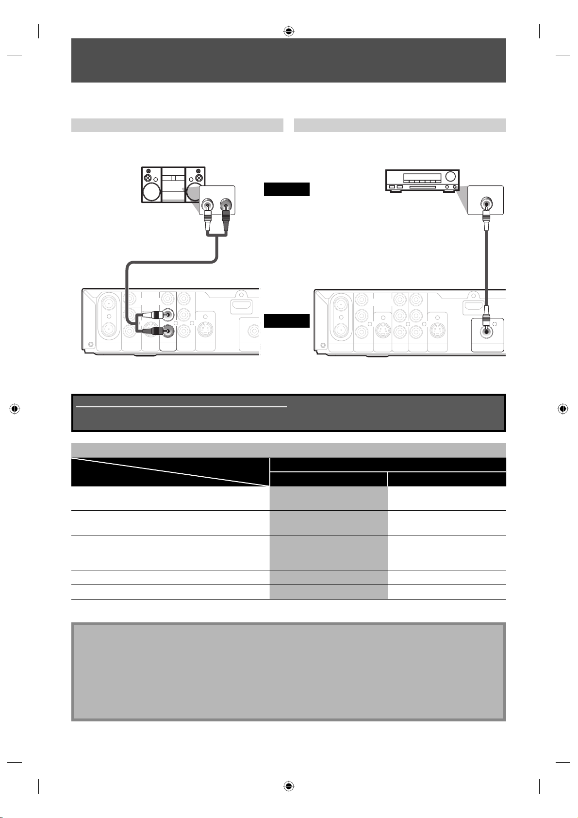
CONNECTION TO AN AUDIO SYSTEM
O
R
• When you change the connections, all devices should be turned off.
• Refer to the owner’s manual accompanying external devices for more information.
Playing Back 2 Channel Analog Audio Playing Back Multi Channel Digital Audio
stereo system
AUDIO IN
RL
audio
analog audio
input jacks
RCA audio cable
IN
VIDEOINVIDEO
OUT
ANTENNA
OUT
L
R
IN OUT
AUDIO IN
S-VIDEO
(L1)
AUDIO OUT
L
R
COMPONENT
Y
PB/CB
PR/CR
VIDEO OUT
S-VIDEO
HDMI OUT
DIGITAL AUDIO
PCM / BITST
this unit
COAXIA
AUDIO OUT
*MD deck or DAT deck can be also connected through coaxial jack.
Supplied cables used in this connection are as follows:
• RCA audio cable (L/R) x 1
Please purchase the rest of the necessary cables at your local store.
Dolby Digital decoder, DTS decoder
digital audio
coaxial input jack
digital audio coaxial cable
IN
VIDEOINVIDEO
OUT
ANTENNA
OUT
L
R
IN OUT
AUDIO IN
S-VIDEO
(L1)
AUDIO OUT
L
R
COMPONENT
Y
PB/CB
PR/CR
VIDEO OUT
S-VIDEO
DIGITAL AUDIO OUTPUT
COAXIAL
HDMI OUT
COAXIAL
DIGITAL AUDIO OUTPUT
PCM / BITSTREAM
Multi Channel Digital Audio Setting
Setting Setup >General Setting >Playback >Audio Out >
Connection Dolby Digital DTS
If output is Dolby Digital encoded audio, connect to
a Dolby Digital decoder.
If output is DTS encoded audio, connect to a DTS
decoder.
Stream OFF
PCM ON
If output is encoded audio for both Dolby Digital and
DTS, connect to the decoder which encodes multiple
Stream ON
audio sources.
Connecting to an MD deck or DAT deck. PCM OFF
If not connected to any external devices. PCM OFF
* To complete these settings, refer to page 98.
Note
• The audio source on a disc in a Dolby Digital multi channel surround format cannot be recorded as digital sound
by an MD or DAT deck.
• By connecting this unit to a Dolby Digital decoder, you can enjoy high-quality Dolby Digital multi channel
surround sound as heard in the movie theaters.
• By connecting this unit to the DTS decoder, you can enjoy Multi-channel Surround System which reproduces the
original sound as truthfully as possible. Multi-channel Surround System is developed by the DTS, Inc.
• Playing back a DVD using incorrect settings may generate noise distortion and may also damage the speakers.
24 EN24 EN
E7M70UD_D-R560KU_EN.indd 24E7M70UD_D-R560KU_EN.indd 24 2007/12/17 11:11:382007/12/17 11:11:38
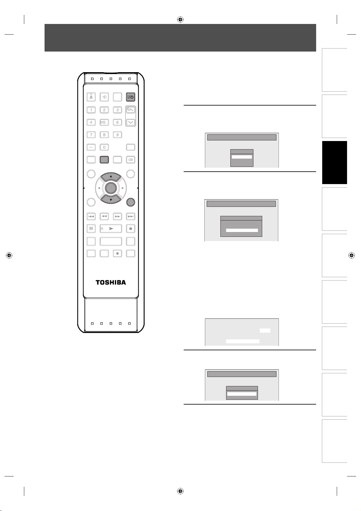
INITIAL SETTING
Turn on this unit for the first time, you need to follow these steps.
Press [I/yy ON/STANDBY].
OPEN/
INPUT
CLOSE
.@/: ABC
GHI
PQRS TUV
DTV/TV
TOP MENU
CLEAR RETURN
SKIP REV
PAU SE
TIME SLIP
HDMI
SELECT
DEF
JKL MNO
WXYZ
SPACE
SETUP
SETUP DISPLAY AUDIO
MENU/LIST
ENTER
ENTER
FWD SKIP
PLAY
1.3x / 0.8x PLAY
REC MODE ZOOMRECREPEAT
SE-R0264
INSTANT SKIP
TIMER
PROG.
RETURN
STOP
1
Before:
Turn the TV on. Select the input to
which the unit is connected.
CH
Use [K / L] to select your desired
language, then press [ENTER] to set
2
language.
Initial Setting
OSD Language
English
Français
Español
Basic Setup
Use [K / L] to select the desired
3
channel preset type then press
[ENTER].
Initial Setting
Channel Preset
Make sure the antenna is
connected to “ANTENNA IN” jack.
Air
Cable
The unit will start getting channels available in
your area.
Air:
(When using antenna)
The channels broadcasted in TV and DTV are
automatically scanned and memorized. Only the
receivable channels in the area where this TV is
used will be memorized.
Cable:
(When using basic cable)
The channels broadcasted in CATV are
automatically scanned and memorized.
Management
Disc
Recording
PlaybackIntroduction Connections
CH 1
Auto Presetting Now
Editing Function Setup
Press [ENTER] to activate “Clock
Setting”.
4
Initial Setting
Clock Setting
- - - / - - / - - - - ( - - - )
- - : - - - -
Proceed to step 5 in “Manual Clock
Setting” on page 30.
5
• If a PBS (public broadcasting station) is
available in your area, press [RETURN] or
[SETUP] to exit, then follow “Auto Clock
Setting” on page 29.
Others
25EN 25EN
E7M70UD_D-R560KU_EN.indd 25E7M70UD_D-R560KU_EN.indd 25 2007/12/17 11:11:402007/12/17 11:11:40
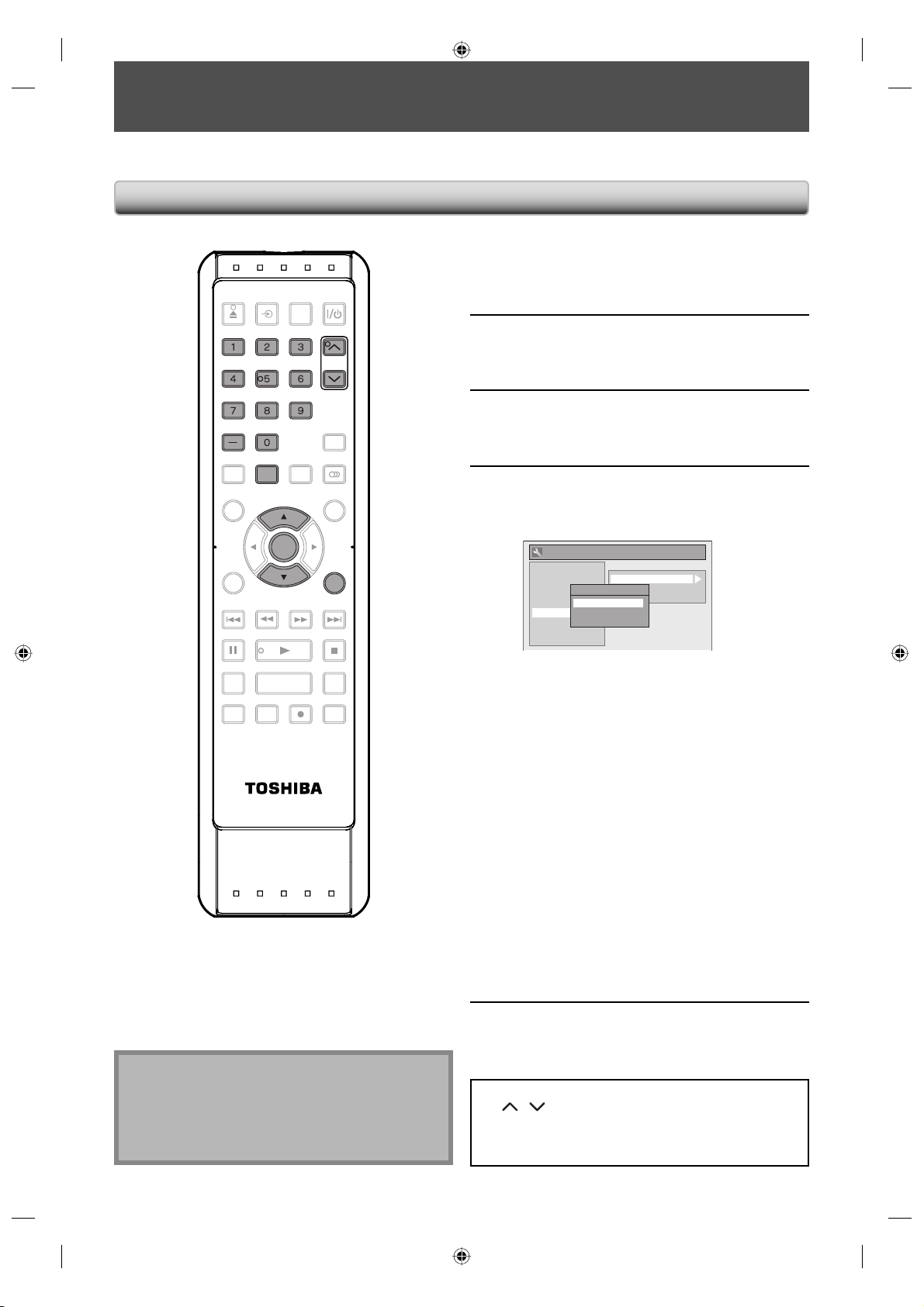
CHANNEL SETTING
If you have changed antenna connection, we recommend that you program available channels in your area with the
following procedures.
Auto Channel Scan
Press [SETUP] and use [K / L] to
OPEN/
INPUT
CLOSE
SELECT
.@/: ABC DEF
.@/: ABC
GHI
JKL MNO
GHI
JKL MNO
PQRS TUV
PQRS TUV
SPACE
SPACE
SETUP
SETUP DISPLAY AUDIO
DTV/TV
HDMI
DEF
WXYZ
WXYZ
CH
CH
TIMER
PROG.
1
2
3
select “General Setting”, then press
[ENTER].
Use [K / L] to select “Channel”, then
press [ENTER].
“Channel” menu will appear.
Use [K / L] to select “Auto Preset”,
then press [ENTER].
TOP MENU
CLEAR RETURN
SKIP REV
PAU SE
1.3x / 0.8x PLAY
TIME SLIP
REC MODE ZOOMRECREPEAT
SE-R0264
ENTER
ENTER
PLAY
MENU/LIST
RETURN
FWD SKIP
STOP
INSTANT SKIP
Use [K / L] to select the type of
broadcasting signal, then press
4
[ENTER].
General Setting
Playback
Display
Video
Recording
Clock
Channel
DivX
HDMI
Reset All
The unit will start getting channels available in
your area.
Air:
(When using antenna)
The channels broadcasted in analog TV and
digital TV are automatically scanned and
memorized. Only the receivable channels in the
area will be memorized.
Cable:
(When using basic cable)
The channels broadcasted in analog CATV are
automatically scanned and memorized.
Cable (Extended Scan):
(When using basic cable)
The channels broadcasted in analog CATV and
digital CATV are automatically scanned and
memorized.
To cancel the auto channel preset during
scanning:
Press [RETURN] or [SETUP] to cancel.
Auto Preset
Manual Preset
Auto Preset
TV Audio Select
Air
Cable
Cable (Extended Scan)
When scanning is over, press [SETUP]
to exit.
Note
• If the auto channel preset is canceled during
presetting, some channels not yet preset may not be
received.
• The selection will depend on how you receive the TV
channels.
5
To cycle through only the memorized channels, use
[CH
/ ].
To select a channel directly (including the ones not
memorized), use [the Number buttons] and [-] (for
digital TV channels).
26 EN26 EN
E7M70UD_D-R560KU_EN.indd 26E7M70UD_D-R560KU_EN.indd 26 2007/12/17 11:11:412007/12/17 11:11:41
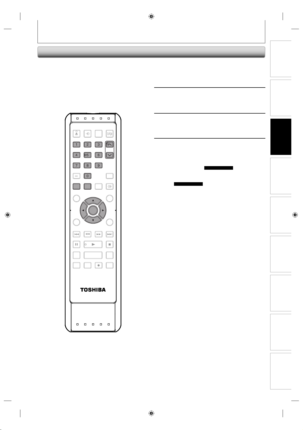
Adding/Deleting Channels
CHANNEL SETTING
You may want to add or delete TV channels if your
channel lineup changes or if you no longer watch some
channels.
Adding channels is only available for the analog TV
channels.
Make sure
• You perform “Auto Channel Scan” before adding or
deleting the channels.
OPEN/
INPUT
CLOSE
.@/: ABC DEF
.@/: ABC
GHI
GHI
PQRS TUV
PQRS TUV
DTV/TV
DTV/TV
TOP MENU
CLEAR RETURN
HDMI
SELECT
DEF
CH
WXYZ
WXYZ
CH
TIMER
PROG.
MENU/LIST
JKL MNO
JKL MNO
SPACE
SPACE
SETUP
SETUP DISPLAY AUDIO
ENTER
ENTER
Press [DTV/TV] to select the mode
(DTV or TV) to/from which you want
1
to add or delete channels.
Press [SETUP] and use [K / L] to
select “General Setting”, then press
2
[ENTER].
Use [K / L] to select “Channel”, then
press [ENTER].
3
“Channel” menu will appear.
Use [K / L] to select “Manual Preset”,
then press [ENTER].
4
“Manual Preset” menu will appear.
• If you are adding or deleting analog TV
channels, go to
continue.
• If you are deleting digital TV channels, go to
DIGITAL
ANALOG
on page 28 to continue
on page 28 to
Basic Setup
Management
Disc
Recording
SKIP REV
PAU SE
TIME SLIP
1.3x / 0.8x PLAY
REC MODE ZOOMRECREPEAT
SE-R0264
FWD SKIP
PLAY
STOP
PlaybackIntroduction Connections
INSTANT SKIP
Editing Function Setup
Others
Instructions continue on the next page.
27EN 27EN
E7M70UD_D-R560KU_EN.indd 27E7M70UD_D-R560KU_EN.indd 27 2007/12/17 11:11:432007/12/17 11:11:43
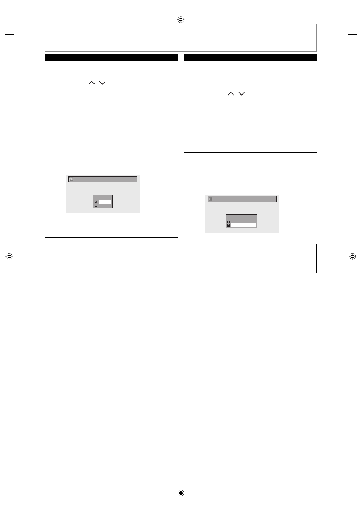
CHANNEL SETTING
ANALOG
Select the channel number to add or
delete.
5
6
• Use [CH / ] to cycle through only the
memorized channels.
• Use [{ / B] to cycle through all the channels
including the ones not memorized.
• Use [the Number buttons] to select a channel
directly.
• When a memorized channel is selected, “Add”
is checked and highlighted as a default.
• When an unmemorized channel is selected,
“Delete” is checked and highlighted as a
default.
Use [K / L] to select “Add” or
“Delete”, then press [ENTER].
Manual Preset
CH 2
Add
Delete
Your setting will be activated and it will
automatically switch to the next channel so that
you can continue adding or deleting channels.
Press [SETUP] to exit.
7
DIGITAL
Select the channel number to delete.
• Only the major channel is displayed in “Manual
5
6
WARNING:
• For the digital TV channels, you cannot recover the
deleted channels once they are deleted unless you
perform the auto channel preset again.
Preset” menu. (The channel number displayed
in the parenthesis is a virtual channel number)
• Use [CH / ] to cycle through only the
memorized channels.
• You cannot use [{ / B] for the digital TV
channel selection.
• Use [the Number buttons] to select a channel
directly.
• When an unmemorized channel is selected
“Delete” is checked and highlighted as a
default.
Use [K / L] to select “Delete”, then
press [ENTER]. Then select the next
channel to delete.
• If the setting is complete, press [RETURN] to
activate “Manual Preset”.
Manual Preset
- - -
)
DTV 2 (CH
Add
Delete
Your setting will be activated.
Press [SETUP] to exit.
7
28 EN28 EN
E7M70UD_D-R560KU_EN.indd 28E7M70UD_D-R560KU_EN.indd 28 2007/12/17 11:11:442007/12/17 11:11:44
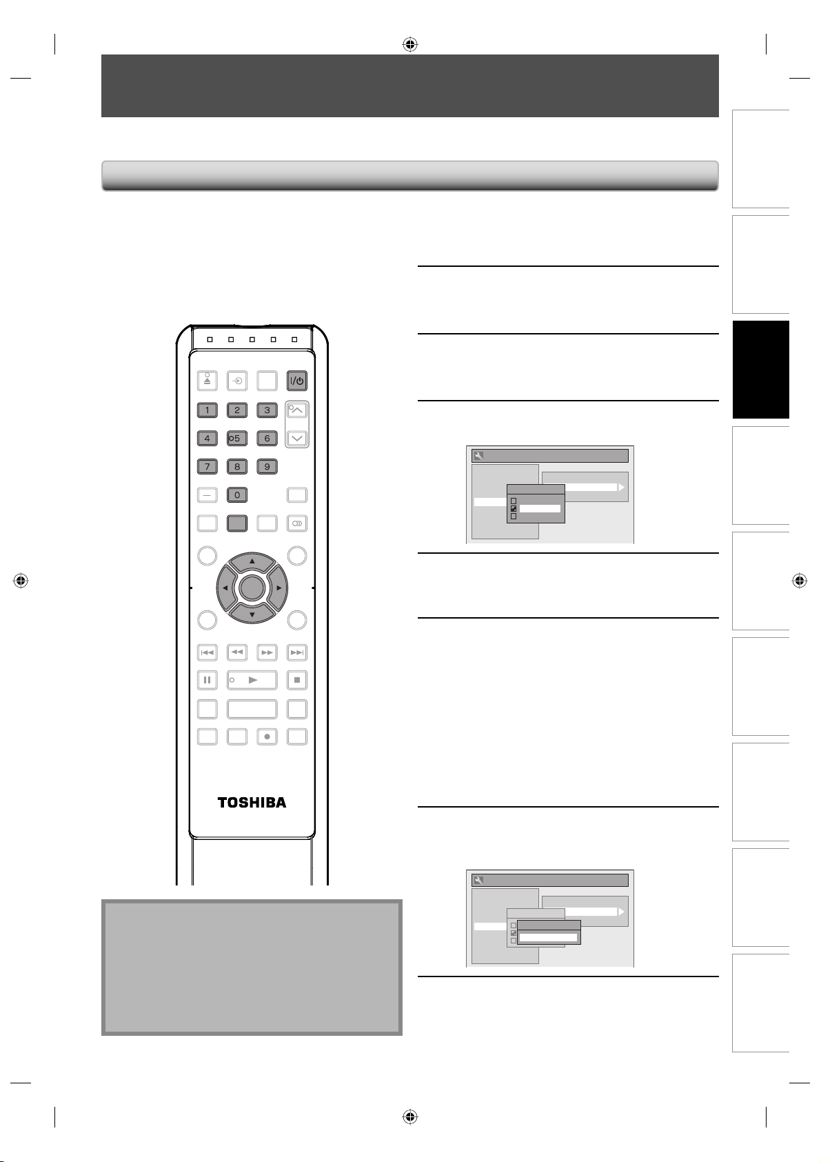
SETTING THE CLOCK
Set the clock before you try the timer programming. If a PBS (public broadcasting station) is available in your area,
follow “Auto Clock Setting” below. If not, follow “Manual Clock Setting” on page 30.
Auto Clock Setting
This unit can set the time and date automatically by
referring to a PBS station.
Make sure
• The antenna/cable TV connections are correct.
• Channels are set. (Refer to pages 26-28.)
• If this unit is connected to a cable/satellite box,
select the local PBS station on them to set the clock
automatically.
OPEN/
INPUT
CLOSE
.@/: ABC DEF
.@/: ABC
GHI
GHI
PQRS TUV
PQRS TUV
DTV/TV
TOP MENU
CLEAR RETURN
HDMI
SELECT
DEF
WXYZ
WXYZ
CH
TIMER
PROG.
MENU/LIST
JKL MNO
JKL MNO
SPACE
SPACE
SETUP
SETUP DISPLAY AUDIO
ENTER
ENTER
Press [SETUP] and use [K / L] to
select “General Setting”, then press
1
[ENTER].
Use [K / L] to select “Clock”, then
press [ENTER].
2
“Clock” menu will appear.
Use [K / L] to select “Auto Clock
Setting”, then press [ENTER].
3
Use [K / L] to select “Auto”, then
press [ENTER].
4
General Setting
Playback
Display
Video
Recording
Clock
Channel
DivX
HDMI
Reset All
Clock Setting
Auto Clock Setting
Auto Clock Setting
Daylight Saving Time
OFF
Auto
Manual
Press [SETUP] to exit.
5
Basic Setup
Management
Disc
Recording
1.3x / 0.8x PLAY
REC MODE ZOOMRECREPEAT
SE-R0264
FWD SKIP
PLAY
STOP
INSTANT SKIP
SKIP REV
PAU SE
TIME SLIP
Note
• The unit receives the clock data at 12:00 a.m/p.m
from the PBS channel when the power is off.
• The clock may set itself automatically after this unit
receive the antenna/cable signal and plug in the
power cord.
• Only the analog PBS channel signal is effective for
auto clock setting.
Press [I/yy ON/STANDBY] to turn off
the unit.
6
If the unit chooses an incorrect PBS channel, set the PBS
channel manually by following the steps below.
This unit will search for the time only when the
power is off. Leave it off for several minutes to
give this unit time to set the clock.
Select “Manual” at step 4, then press
[ENTER].
1
Use [the Number buttons] or [K / L]
to enter your PBS channel number,
2
then press [ENTER].
General Setting
Playback
Display
Video
Recording
Clock
Channel
DivX
HDMI
Reset All
Clock Setting
Auto Clock Setting
Auto Clock Setting
Daylight Saving Time
Set Channel No.
OFF
Auto
CH 1
Manual
Press [SETUP] to exit and turn off the
unit.
3
PlaybackIntroduction Connections
Editing Function Setup
Others
29EN 29EN
E7M70UD_D-R560KU_EN.indd 29E7M70UD_D-R560KU_EN.indd 29 2007/12/17 11:11:452007/12/17 11:11:45
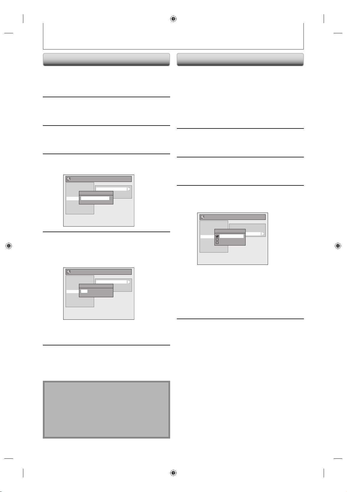
SETTING THE CLOCK
Manual Clock Setting
Press [SETUP] and use [K / L] to
select “General Setting”, then press
1
2
[ENTER].
Use [K / L] to select “Clock”, then
press [ENTER].
“Clock” menu will appear.
Use [K / L] to select “Clock Setting”,
then press [ENTER].
3
Use [K / L] to select calendar or time,
then press [ENTER].
4
5
General Setting
Playback
Display
Video
Recording
Clock
Channel
DivX
HDMI
Reset All
Use [{ / B] to select an item to set,
and use [K / L] to select the contents
to suit your preference, then press
[ENTER].
General Setting
Playback
Display
Video
Recording
Clock
Channel
DivX
HDMI
Reset All
Clock Setting
Auto Clock Setting
Clock Setting
Daylight Saving Time
JAN / 01 / 2008 ( TUE )
12 : 00 AM
Clock Setting
Auto Clock Setting
Clock Setting
Daylight Saving Time
JAN / 01 / 2008 ( TUE )
12 : 00 AM
Daylight Saving Time
When “Daylight Saving Time” is “ON”, the unit clock will
automatically adjust the time in order to fit the daylight
saving time.
“ON (MAR - NOV)” has been selected as the default.
Press [SETUP] and use [K / L] to
select “General Setting”, then press
1
2
[ENTER].
Use [K / L] to select “Clock”, then
press [ENTER].
“Clock” menu will appear.
Use [K / L] to select “Daylight Saving
Time”, then press [ENTER].
3
Use [K / L] to select “ON (MAR -
NOV)”, “ON (APR - OCT)” or “OFF”,
4
then press [ENTER].
General Setting
Playback
Display
Video
Recording
Clock
Channel
DivX
HDMI
Reset All
ON (MAR - NOV):
Move forward one hour on the second Sunday in
March and move back one hour on the first
Sunday in November.
ON (APR - OCT):
Move forward one hour on the first Sunday in
April and move back one hour on the last
Sunday in October.
Clock Setting
Auto Clock Setting
Daylight Saving Time
Daylight Saving Time
ON (MAR - NOV)
ON (APR - OCT)
OFF
Your setting will be activated.
The clock start counting when you press
[ENTER].
Press [SETUP] to exit.
Press [SETUP] to exit.
5
6
Note
• Your clock setting will be lost if either there is a power
failure or this unit has been unplugged for more than
30 seconds when you set the clock manually.
• For setting the day, year, hour and minute,
[the Number buttons] can also be used.
• You can set the built-in calendar from the year 2007
up to 2057.
30 EN30 EN
E7M70UD_D-R560KU_EN.indd 30E7M70UD_D-R560KU_EN.indd 30 2007/12/17 11:11:462007/12/17 11:11:46
 Loading...