


 Loading...
FILE NO. 810-2009108
15-in, 19-in, 22-in, 26-in class LCD TV/DVD COMBINATION
15SLDT3R
19SLDT3R
22SLDT3R
26SLDT3R
The above models are classified as green products (*1), as indicated by the underlined serial numbers. This Service Manual describes replacement parts for the green products. When repairing these green product(s), use the part(s) described in this manual and lead-free solder (*2).
For (*1) and (*2), see the next page.
©2009 Toshiba Corporation |
DOCUMENT CREATED IN TAIWAN, SEPT, 2009 GREEN |

GREEN PRODUCT PROCUREMENT
(*1)
The EC is actively promoting the WEEE & RoHS Directives that define standards for recycling and reuse of Waste Electrical and Electronic Equipment and for the Restriction of the use of certain Hazardous Substances. From July 1, 2006, the RoHS Directive will prohibit any marketing of new products containing the restricted substances.
Increasing attention is given to issues related to the global environmental. Toshiba Corporation recognizes environmental protection as a key management tasks, and is doing its utmost to enhance and improve the quality and scope of its environmental activities. In line with this, Toshiba proactively promotes Green Procurement, and seeks to purchase and use products, parts and materials that have low environmental impacts.
Green procurement of parts is not only confined to manufacture. The same green parts used in manufacture must also be used as replacement parts.
LEAD-FREE SOLDER
(*2)
This product is manufactured using lead-free solder as a part of a movement within the consumer products industry at large to be environmentally responsible. Lead-free solder must be used in the servicing and repair of this product.
WARNING
This product is manufactured using lead free solder.
DO NOT USE LEAD BASED SOLDER TO REPAIR THIS PRODUCT !
The melting temperature of lead-free solder is higher than that of leaded solder by 86°F to 104°F (30°C to 40°C). Use of a soldering iron designed for lead-based solders to repair product made with lead-free solder may result in damage to the component and or PCB being soldered. Great care should be made to ensure high-quality soldering when servicing this product — especially when soldering large components, through-hole pins, and on PCBs — as the level of heat required to melt lead-free solder is high.
Table of Contents |
|
|
1. |
Safety Notices and Precautions |
..................................................................................................... 4 |
2. |
General Specifications................................................................................................................... |
6 |
3. |
Function Testing............................................................................................................................ |
7 |
|
Remote Control Key Codes.......................................................................................................................... |
7 |
|
Hotel Mode Function..................................................................................................................................... |
8 |
4. |
System Disassembly ................................................................................................................... |
10 |
|
Disassembly Tools...................................................................................................................................... |
10 |
|
Disassembly Reminders ............................................................................................................................. |
10 |
5. |
Exploded Diagram....................................................................................................................... |
60 |
6. |
Packing diagram.......................................................................................................................... |
68 |
7. |
Block Diagrams ........................................................................................................................... |
72 |
8. |
Printed Circuit Board ................................................................................................................... |
75 |
9. |
Interconnection diagram.............................................................................................................. |
77 |
10. Troubleshooting......................................................................................................................... |
80 |
|
11. Firmware.................................................................................................................................... |
84 |
|
3
1. Safety Notices and Precautions
Prior to using this service guide, ensure that you have carefully followed all the procedures outlined in the 15SLDT3R/19SLDT3R/22SLDT3R/26SLDT3R LCD TV user manual. Make sure to note and follow all warnings and instructions marked on the product. Save these instructions for future reference.
The LCD TV should be installed on a solid horizontal base.
Do not use the LCD TV near water.
Avoid exposing the LCD TV to moisture or high humidity.
Do not install near any heat sources such as radiators, heat registers, stoves or any other equipment (including amplifiers) that produce heat.
Avoid exposing the LCD TV to direct sunlight or high temperatures. Hot air may cause damage to the cabinet and other parts.
Slots and openings in cabinet and the back or bottom are provided for ventilation. Adequate ventilation must be maintained to ensure reliable and continued operation and to protect the display from overheating. Observe the following.
Do not block ventilation slots and openings with objects or install the display in a place where ventilation may be hindered.
The ventilation slots should never be blocked by placing the product on a bed, sofa, rug, or other similar surface.
This product should not be placed in built-installation unless proper ventilation is provided.
Do not install this display near a motor or transformer where strong magnetism is generated. Images on the display will become distorted and the color irregular.
When cleaning, use only a neutral detergent cleaner with a soft damp cloth. Do not spray with liquid aerosol cleaners.
Refer all servicing to qualified service personnel. Do not attempt repairs yourself. Your warranty does not cover repairs or attempted repairs by anyone not authorized by the manufacturer.
CAUTION
THIS LCD COLOR TELEVISION EMPLOYS A LASER SYSTEM.
TO ENSURE PROPER USE OF THIS PRODUCT, PLEASE READ THIS SERVICE MANUAL CAREFULLY AND RETAIN FOR FUTURE REFERENCE. SHOULD THE UNIT REQUIRE MAINTENANCE, CONTACT AN AUTHORIZED SERVICE LOCATION-SEE SERVICE PROCEDURE.
USE OF CONTROLS, ADJUSTMENTS OR THE PERFORMANCE OF PROCEDURES OTHER THAN THOSE SPECIFIED HEREIN MAY RESULT IN HAZARDOUS RADIATION EXPOSURE.
TO PREVENT DIRECT EXPOSURE TO LASER BEAM, DO NOT TRY TO OPEN THE ENCLOSURE.
VISIBLE LASER RADIATION MAY BE PRESENT WHEN THE ENCLOSURE IS OPENED. DO NOT STARE INTO BEAM.
4
Preparation of Servicing
The laser diode used for a pickup head may be destroyed with external static electricity.
Moreover, even if it is operating normally after repair, when static electricity discharge is received at the time of repair, the life of the product may be shortened.
Please perform the following measure against static electricity, be careful of destruction of a laser diode at the time of repair.
Place the unit on a workstation equipped to protect against static electricity, such as conductive mat.
Soldering iron with ground wire or ceramic type is used.
A worker needs to use a ground conductive wrist strap for body.
Servicing Environment
1.This LCD TV should be used only with the power source type identified on the package and on the user’s guide.
2.Service the LCD TV in a room with low humidity and free of dust.
3.Place the LCD TV on a stable, level surface. Subjecting the LCD TV to a drop or sharp impact may cause severe damage to thin glass, plastic surface materials, and internal components.
4.If necessary, clean the LCD TV with a slightly damp cloth using clean water. Disconnect the LCD
TV from the power source before cleaning. Do not use ammonia-based cleaning products.
5.In the event that the powered LCD TV rapidly heats, or emits unusual smells or noises, immediately disconnect the unit from the power source.
6.To avoid electrical hazard, make sure that the LCD TV is fully assembled—the casing closed and all the screws tightened completely—before plugging it in for testing.
7.The LCD TV’s internal components may be damaged by electrostatic discharge (ESD). Carry out repairs in an ESD-protected workshop. If no such workshop is available, wear an antistatic wrist strap or touch a highly conductive metal object.
8.Before opening the housing, disconnect the LCD TV from all power sources and remove all peripheral cables. If the LCD TV has not been disconnected from the power outlet before being opened, there is a danger to life through electric shock. There is also a risk of damage to the components.
5
2. General Specifications
The product specifications listed in this section are subject to change without notice.
Item |
Description |
|
|
|
|
|
|
|
|
|
|
|
|
|
|
Model Name |
15SLDT3R |
|
19SLDT3R |
|
22SLDT3R |
26SLDT3R |
|
|
|
|
|
|
|
|
|
Panel |
|
|
|
|
|
|
|
|
|
|
|
|
|
|
|
Size (approximate screen |
15.6 in (396.24 mm) |
|
18.5 in (469.9 mm) |
|
21.6 in (548.64 mm) |
26.0 in |
|
size, diagonal) |
|
|
|
|
|
|
|
|
|
|
|
|
|
|
|
Type |
Low-glass Active Matrix TFT color LCD |
|
|
||||
|
|
|
|
|
|
||
Resolution |
1366 x 768 (RGB vertical stripe) |
|
|
||||
|
|
|
|
|
|
|
|
Viewing angle |
170° (H) / 160° (V) |
|
|
|
|
|
|
|
|
|
|
|
|
||
TV System |
SECAM D/K Russia, RFQ requires B/G, D/K, I/I, L |
|
|
||||
|
|
|
|
|
|
||
AV input receivable |
NTSC 3.58, NTSC 4.43, PAL-60 |
|
|
||||
|
|
|
|
|
|
||
Antenna input |
VHF / UHF 75 ohm unbalanced |
|
|
||||
|
|
|
|
|
|
|
|
DVD/CD Player |
|
|
|
|
|
|
|
|
|
|
|
|
|
|
|
Signal system |
PAL, NTSC |
|
|
|
|
|
|
|
|
|
|
|
|
|
|
Supported disc size |
12 cm, 8 cm |
|
|
|
|
|
|
|
|
|
|
|
|
|
|
Audio/Video Input/Output Signals |
|
|
|
|
|
||
|
|
|
|
|
|
||
S-Video input |
(Y) 1.0 V (p-p), 75 ohm, negative sync, 4-pin mini-DIN x 1 |
|
|
||||
|
(C) 1.0 V (p-p), 75 ohm |
|
|
|
|
|
|
|
|
|
|
|
|
||
ColorStream video input |
(Y) 1.0 V (p-p), 75 ohm, negative sync, RCA jack x 1 |
|
|
||||
(component) |
(Pb, Pr) 0.7 V (p-p), 75 ohm, RCA jack x 2 |
|
|
||||
|
|
|
|
|
|
||
Video input (composite) |
1.0 V (p-p), 75 ohm, negative sync, RCA jack x 1 |
|
|
||||
|
|
|
|
|
|
||
Analog audio output |
-10.7 dBm, 47 kohm, RCA jack (L/R) x 2 |
|
|
||||
|
|
|
|
|
|
||
Digital audio output |
0.5 V (p-p), 75 ohm, coaxial jack x 1 |
|
|
||||
|
|
|
|
|
|
|
|
Headphone |
3.5-mm stereo mini jack x 1 |
|
|
|
|
|
|
|
|
|
|
|
|||
PC input |
Monitor: 15-pin mini-D sub x 1; audio: 3.5-mm stereo mini jack x 1 |
|
|||||
|
|
|
|
|
|
|
|
Speaker Output |
1.5 W x 2 |
|
|
|
|
10 W x 2 |
|
|
|
|
|
|
|
|
|
Power Voltage |
220-240 VAC, 50 Hz |
|
|
|
|
|
|
|
|
|
|
|
|
|
|
Power Consumption (DC) |
|
|
|
|
|
|
|
|
|
|
|
|
|
|
|
Operation |
33 W |
|
35 W |
|
55 W |
100 W |
|
|
|
|
|
|
|
|
|
Standby |
0.8 W |
|
|
|
|
|
|
|
|
|
|
|
|
|
|
Operating Conditions |
|
|
|
|
|
|
|
|
|
|
|
|
|
|
|
Temperature |
+5-35 °C (41-95 °F) |
|
|
|
|
|
|
|
|
|
|
|
|
||
Relative humidity |
Less than 80% RH (no condensation) |
|
|
||||
|
|
|
|
|
|
|
|
Dimensions (W x D x H) |
15.84 x 12.59 x 5.55 in |
|
18.58 x 15.79 x 8.15 in |
|
21.12 x 17.3 x 8.15 in |
26.83 x 20.16 x 8.99 in |
|
|
(402.4 x 319.7 x 141 mm) |
|
(472 x 401 x 207 mm) |
|
(536.5 x 439.5 x 207 mm) |
(681.4 x 512.1 x 228.3 mm) |
|
|
|
|
|
|
|
|
|
Weight |
2.99 kg (6.59 lb) |
|
4.63 kg (10.21 lb) |
|
5.3 kg (11.68 lb) |
8.57 kg (18.89 lb) |
|
|
|
|
|
|
|
|
|
Warning! Do not set your computer graphics card to exceed the unit’s refresh rates; doing so may cause damage to the LCD TV.
6
3. Function Testing
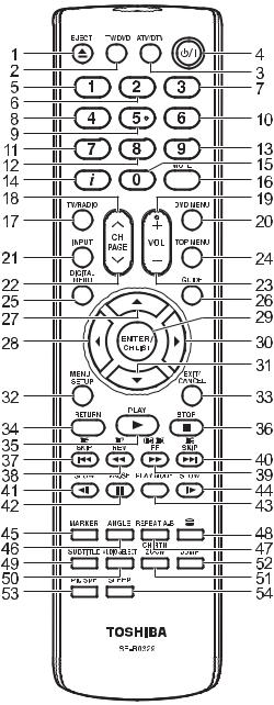
Remote Control Key Codes
Notes: |
1.NEC Format
2.Custom Code: 40-BF H, 44-BB H, 45-BA H, 45-BC H
No. |
Key Name |
Custom Code |
Key Code |
1 |
EJECT |
45-BA |
F5 |
2 |
TV/DVD |
45-BC |
B3 |
3 |
ATV/DTV |
40-BF |
44 |
4 |
POWER |
40-BF |
12 |
5 |
1 |
40-BF |
01 |
6 |
2 |
40-BF |
02 |
7 |
3 |
40-BF |
03 |
8 |
4 |
40-BF |
04 |
9 |
5 |
40-BF |
05 |
10 |
6 |
40-BF |
06 |
11 |
7 |
40-BF |
07 |
12 |
8 |
40-BF |
08 |
13 |
9 |
40-BF |
09 |
14 |
DISPLAY |
40-BF |
1C |
15 |
0 |
40-BF |
00 |
16 |
MUTE |
40-BF |
10 |
17 |
TV/RADIO |
40-BF |
47 |
18 |
CH UP |
40-BF |
3E |
19 |
VOL+ |
40-BF |
1A |
20 |
DVD MENU |
40-BF |
19 |
21 |
INPUT |
40-BF |
0F |
22 |
CH DOWN |
40-BF |
3F |
3F |
VOL - |
40-BF |
1E |
24 |
TOP MENU |
44-BB |
DF |
25 |
DIGITAL MENU |
40-BF |
0A |
26 |
GUIDE |
40-BF |
45 |
27 |
UP |
44-BB |
80 |
28 |
LEFT |
44-BB |
51 |
29 |
ENTER/CH LIST |
40-BF |
3D |
30 |
RIGHT |
44-BB |
4D |
31 |
DOWN |
44-BB |
81 |
32 |
MENU SETUP |
40-BF |
0E |
33 |
EXIT / CANCEL |
44-BB |
EF |
34 |
RETURN |
44-BB |
5D |
35 |
PLAY |
44-BB |
15 |
36 |
STOP |
44-BB |
14 |
37 |
|<< SKIP |
45-BA |
23 |
38 |
<< REV |
45-BA |
19 |
39 |
FF >> |
45-BA |
13 |
40 |
SKIP >>| |
45-BA |
24 |
41 |
SLOW <| |
45-BA |
0E |
42 |
PAUSE |
45-BA |
15 |
43 |
PLAY MODE |
45-BA |
E0 |
44 |
SLOW |> |
45-BA |
0D |
45 |
MARKER |
45-BA |
EC |
46 |
ANGLE |
44-BB |
96 |
47 |
REPEAT A-B |
44-BB |
5C |
48 |
TELETEXT |
45-BA |
79 |
49 |
SUBTITLE |
44-BB |
87 |
No. |
Key Name |
Custom Code |
Key Code |
50 |
AUDIO SELECT |
44-BB |
53 |
51 |
CH RTN ZOOM |
45-BA |
40 |
52 |
JUMP |
44-BB |
9B |
53 |
PIC SIZE |
40-BF |
59 |
54 |
SLEEP |
40-BF |
15 |
7
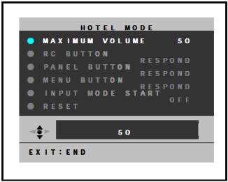
Hotel Mode Function
To set the Hotel mode, please follow the steps below:
1.In power on mode, set the VOLUME to minimum.
Press and hold the VOLUME DOWN button on the side panel.
2.Simultaneously press and hold the channel button (7) on the remote control for more than 2 seconds.
The Hotel mode setting menu will appear.
3.Using the UP/DOWN button on the remote control, select RESET. Then press the ENTER button.
4.Using the LEFT/RIGHT button on the remote control, set the item to the desired setting. The Hotel mode has now been set up.
To reset the Hotel mode, please follow the steps below:
1.In power on mode, set the VOLUME to minimum.
Press and hold the VOLUME DOWN button on the side panel.
2.Simultaneously press and hold the channel button (7) on the remote control for more than
2 seconds.
The Hotel mode setting menu will appear.
3.Using the UP/DOWN button on the remote control, select RESET. Then press the ENTER button.
The setting items have now been returned to initial value.
Setting item |
Setting value |
Initial value |
Function |
|
|
|
|
Maximum |
0-50 |
50 |
Setting of the maximum volume value. |
volume |
|
|
|
|
|
|
|
RC button |
RESPOND/ |
RESPOND |
Effective/invalid setting of remote control key |
|
NO RESPOND |
|
operation (Note 1). |
|
|
|
|
Panel button |
|
|
Effective/invalid setting of main key operation (Note |
|
|
|
2). |
|
|
|
|
Menu button |
|
|
Effective/invalid setting of menu, DTV menu and |
|
|
|
GUIDE keys operation of set and remote control |
|
|
|
(Note 1). |
|
|
|
|
Input mode start |
1-99ch/DTV/AV1/AV2/ |
OFF |
Setting of input source at power supply On. (Note |
|
COMPONENT/HDMI/ |
|
3) |
|
PC/DVD/OFF |
|
|
|
|
|
|
Reset |
- |
- |
Various setting of the Hotel mode function returns |
|
|
|
initial state. |
|
|
|
|
Notes: |
|
|
|
1.Even if set to “No Respond”, the remote control key operation in Hotel mode and service mode function are effective.
2.Even if set to “No Respond”, the service mode function is effective.
3.If set to “Off”, it starts up in the same input source before you turn off the power.
9
4. System Disassembly
Disassembly Tools
The following tools are required for disassembling the system.
Wrist-grounding strap and conductive mat for preventing electrostatic discharge
Philips screwdriver
Hex screwdriver
Disassembly Reminders
Electrostatic Discharge (ESD) precautions should be observed to prevent damaging the internal components.
Follow the sequence indicated in the illustrative figures when removing the screws securing the components.
The screws for the different components vary in size. During the disassembly process, group the screws with their corresponding components to avoid mismatches when putting back the components.
After removing the adhesive tapes, paste them back near their original location for use during system reassembly.
Prior to disassembly, place the LCD TV on a stable, level surface protected by a cushion.
10
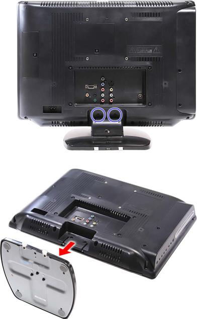
15SLDT3R
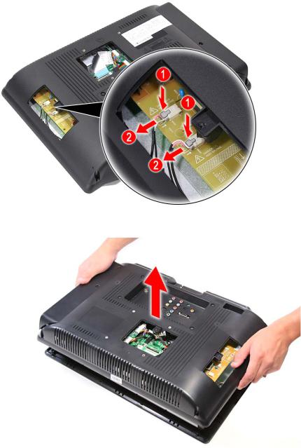
1.Lay down the LCD TV on a flat, stable surface with the rear cover facing up. Make sure the lip edge of the front bezel is hanging over the edge of the surface.
2.Remove the screws securing the LCD TV base
3. Remove LCD TV base.
11
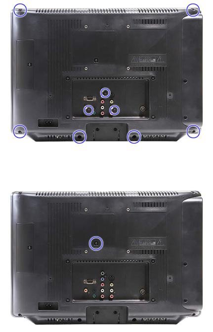
4. Remove the screws securing the rear panel cover.
5. Remove the screw securing the left rear panel door.
12
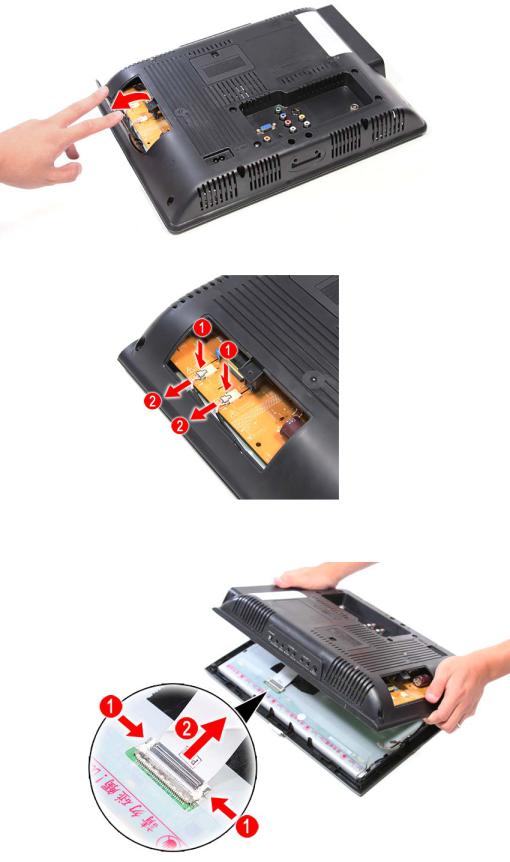
6. Open and remove the left rear panel door.
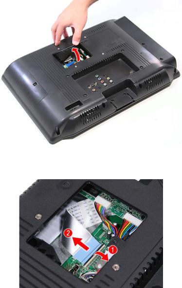
7. Disconnect the power cables.
8.Detach the top part of the rear panel cover from the housing and tilt it back to expose the
LCD cable on the LCD panel; then disconnect the LCD cable, and remove the rear panel.
Caution: As FFC connector for LCD panel can easily be damaged during disassembly or reassembly, handle it with care.
13
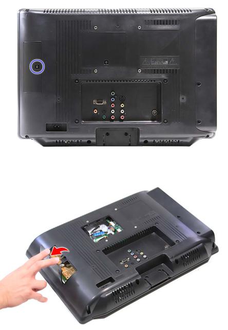
Note: Take note of the spring orientation when reassembling the TV.
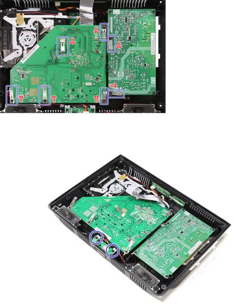
9. Remove the screws securing the IR board.
14
10.Disconnect the cable from the LED board; then pull up to remove the IR board.
11.Remove the screws from the control board.
15
12.Disconnect the cable from the control board; then remove the control board.
13.Unlatch the control board from its plastic bracket to separate it from its case.
16
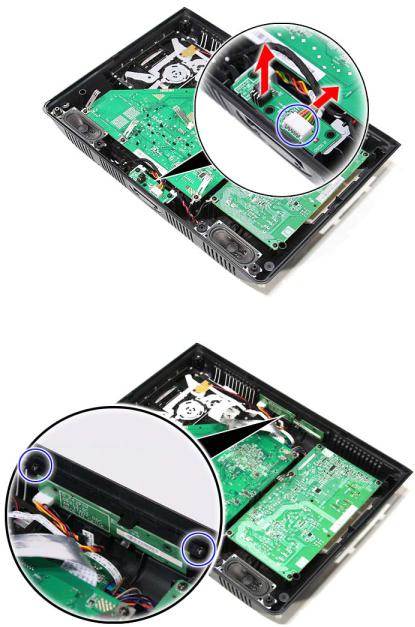
14.Remove the screws securing the power board.
15.Lift up the power board at an angle; then disconnect the two cables, and remove the power board.
 .
.
17
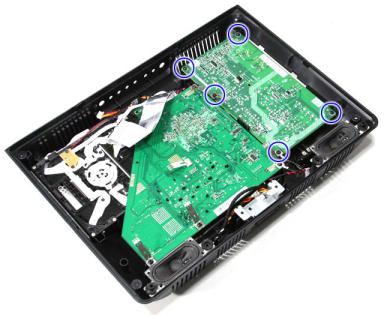
16.Remove the screws securing the mainboard.
17.Lift the mainboard at an angle; then disconnect the cable.
18

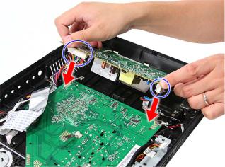
18.Lift up the mainboard; then disconnect the two cables.
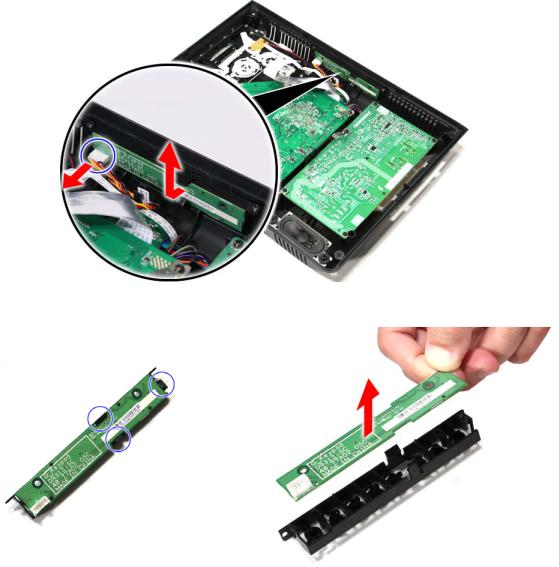
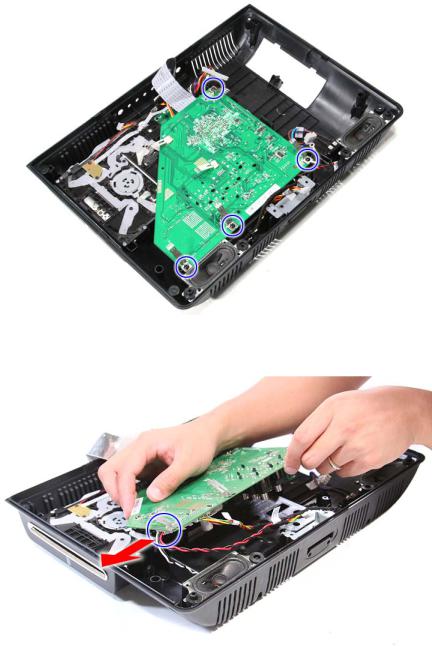
19.Remove the screws securing the optical drive.
19
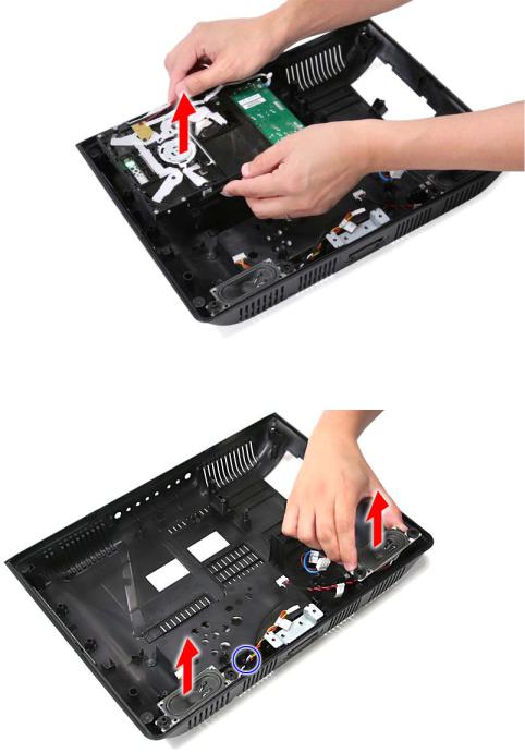
20.Lift up and remove the optical drive.
21.Pull up to release the left and right speakers. Take note to release the speaker cables from their latch.
20
22.Release the LCD panel from its latches.
23.Remove the LCD panel from the front bezel.
21
19SLDT3R
1.Lay down the LCD TV on a flat, stable surface with the rear cover facing up. Make sure the lip edge of the front bezel is hanging over the edge of the surface.
2.Remove the screws securing the LCD TV base
3. Remove LCD TV base.
22
4. Remove the screws securing the rear panel cover.
5. Remove the screw securing the center rear panel door.
23
6. Open and remove the center rear panel door.
7. Disconnect the LCD cable.
Caution: As FFC connector for LCD panel can easily be damaged during disassembly or reassembly, handle it with care.
24
8. Remove the screw securing the left rear panel door.
9. Open and remove the left rear panel door.
25
10.Disconnect the power cables.
11.Detach the top part of the rear panel cover from the housing, and remove the rear panel.
26

Note: Take note of the spring orientation when reassembling the TV.
12.Remove the screw securing the IR board.
27
Loading...