

Page 1

FILE NO. 810-200967GR
SERVICE MANUAL
LCD TV/DVD COMBINATION
19DV616DG
22DV616DG
The above models are classified as green products (*1), as indicated by the underlined serial numbers.
This Service Manual describes replacement parts for the green products. When repairing these green
product(s), use the part(s) described in this manual and lead-free solder (*2).
For (*1) and (*2), see the next page.
©2009 Toshiba Corporation
DOCUMENT CREATED IN JAPAN, June, 2009 GREEN
Page 2

g
The EC is actively promoting the WEEE & RoHS Directives that define standards for recycling
and reuse of Waste Electrical and Electronic Equipment and for the Restriction of the use of
certain Hazardous Substances. From July 1, 2006, the RoHS Directive will prohibit any
marketing of new products containing the restricted substances.
Increasing attention is given to issues related to the global environmental. Toshiba Corporation
recognizes environmental protection as a key management tasks, and is doing its utmost to
enhance and improve the quality and scope of its environmental activities. In line with this,
Toshiba proactively promotes Green Procurement, and seeks to purchase and use products,
parts and materials that have low environmental impacts.
Green procurement of parts is not only confined to manufacture. The same green parts used in
manufacture must also be used as replacement parts.
GREEN PRODUCT PROCUREMENT
This product is manufactured using lead-free solder as a part of a movement within the consumer
products industry at large to be environmentally responsible. Lead-free solder must be used in
the servicing and repair of this product.
LEAD-FREE SOLDER
WARNING
This product is manufactured using lead free solder.
DO NOT USE LEAD BASED SOLDER TO REPAIR THIS PRODUCT !
o
with lead-free solder may result in damage to the component and or PCB being soldered. Great
care should be made to ensure high-quality soldering when servicing this product especially
when solderin
required to melt lead-free solder is high.
o
large components, through-hole pins, and on PCBs as the level of heat
-
-
o
o
19DV616DG/22DV616DG
Page 3

…
…
…
…
…
…
…
…
…
…
…
…
…
…
…
…
…
…
…
…
…
…
…
…
…
A
…
…
A
…
…
…
TABLE OF CONTENT
S
• GREEN PRODUCT PROCUREMENT
• LEAD-FREE SOLDER
• TABLE OF CONTENTS
• OWNER'S MANUAL
SERVICING NOTICES ON CHECKING…………………………………………………………………
HOW TO ORDER PARTS…………………………………………………………………………………
IMPORTANT………………………………………………………………………………………………
WHEN REPLACING DVD DECK…………………………………………………………………………
DISC REMOVAL METHOD AT NO POWER SUPPLY………………………………………………
PARENTAL CONTROL - RATING LEVEL……………………………………………………………
HOTEL MODE FUNCTION………………………………………………………………………………
TRAY LOCK………………………………………………………………………………………………
REMOTE CONTROL KEY CODE………………………………………………………………………
GENERAL SPECIFICATIONS……………………………………………………………………………
DISASSEMBLY INSTRUCTIONS
1. REMOVAL OF MECHANICAL PARTS AND P. C. BOARDS…………………………………
2. REMOVAL OF DVD DECK PARTS………………………………………………………………
3. REMOVAL AND INSTALLATION OF FLAT PACKAGE IC……………………………………
SERVICE MODE LIST……………………………………………………………………………………
SERVICING FIXTURES AND TOOLS…………………………………………………………………
RE-WRITE FOR DVD FIRMWARE………………………………………………………………………
WHEN REPLACING EEPROM (MEMORY) IC…………………………………………………………
ELECTRICAL ADJUSTMENTS…………………………………………………………………………
TROUBLESHOOTING GUIDE……………………………………………………………………………
BLOCK DIAGRAMS
DVD………………………………………………………………………………………………………
POWER…………………………………………………………………………………………………
21PIN/TUNER…………………………………………………………………………………………
REGULATOR…………………………………………………………………………………………… F-9, F-10
SCALER/SUB MICON…………………………………………………………………………………
SOUND AMP/AV SWITCH/JACK/INTERFACE_HDMI IC…………………………………………
DIGITAL…………………………………………………………………………………………………
PRINTED CIRCUIT BOARDS
DVD MT…………………………………………………………………………………………………
DIGITAL…………………………………………………………………………………………………
MAIN/TUNER…………………………………………………………………………………………… G-9~G-16
POWER/OPERATION/REMOCON…………………………………………………………………
LOADING MOTOR/PCB………………………………………………………………………………
SCHEMATIC DIAGRAMS
MPEG/MICON/DSP/RF_AMP………………………………………………………………………… H-1~H-4
MEMORY………………………………………………………………………………………………
MOTOR DRIVE…………………………………………………………………………………………
UDIO/VIDEO……………………………………………………………………………………………H-13~H-16
21PIN……………………………………………………………………………………………………
REGULATOR…………………………………………………………………………………………… H-21~H-24
REGULATOR2…………………………………………………………………………………………
V SWITCH………………………………………………………………………………………………H-29~H-32
SOUND AMP MUTE……………………………………………………………………………………
TUNER…………………………………………………………………………………………………
SCALER…………………………………………………………………………………………………
A1-1
A1-1
A1-1
A1-2
A1-3
A1-3
A1-4
A1-4
A1-5
A2-1~A2-12
B1-1~B1-6
B2-1~B2-5
B3-1, B3-2
C-1
C-2
C-2
C-3, C-4
D-1~D-14
E-1~E-10
F-1, F-2
F-3~F-6
F-7, F-8
F-11, F-12
F-13, F-14
F-15, F-16
G-1~G-4
G-5~G-8
G-17~G-24
G-25
H-5~H-8
H-9~H-12
H-17~H-20
H-25~H-28
H-33~H-36
H-37~H-40
H-41~H-44
19DV616DG/22DV616DG
Page 4

…
…
…
…
A
…
…
…
…
…
…
…
…
…
…
…
…
…
TABLE OF CONTENT
S
SUB MICON………………………………………………………………………………………………H-45~H-48
JACK……………………………………………………………………………………………………
INTERFACE_HDMI IC…………………………………………………………………………………
DVD_INTERFACE/AV_SWITCH……………………………………………………………………
PANEL_INTERFACE…………………………………………………………………………………
SIC……………………………………………………………………………………………………… H-65~H-68
FLASH/SDRAM…………………………………………………………………………………………
COMMON INTERFACE………………………………………………………………………………
POWER IN/OUT………………………………………………………………………………………
OFDM_DEMODULATOR……………………………………………………………………………… H-81~H-84
POWER…………………………………………………………………………………………………
BACKLIGHT INVERTER………………………………………………………………………………
SOUND AMP……………………………………………………………………………………………
JACK OUT………………………………………………………………………………………………
LOADING MOTOR……………………………………………………………………………………
INTERCONNECTION DIAGRAM………………………………………………………………………
WAVEFORMS………………………………………………………………………………………………
MECHANICAL EXPLODED VIEWS……………………………………………………………………
DVD DECK EXPLODED VIEW…………………………………………………………………………
MECHANICAL REPLACEMENT PARTS LIST…………………………………………………………
DVD DECK REPLACEMENT PARTS LIST……………………………………………………………
ELECTRICAL REPLACEMENT PARTS LIST…………………………………………………………
H-49~H-52
H-53~H-56
H-57~H-60
H-61~H-64
H-69~H-72
H-73~H-76
H-77~H-80
H-85~H-88
H-89~H-92
H-93~H-96
H-97~H-100
H-101, H-102
H-103~H-106
I-1, I-2
J1-1~J1-6
J2-1
K1-1~K1-4
K2-1, K2-2
K3-1~K3-10
19DV616DG/22DV616DG
Page 5
EU Conformity Statement
“This product is marked with “CE” and complies therefore with the applicable harmonized European
standards listed under the Low Voltage Directive 2006/95/EC and the EMC Directive 2004/108/EC.”
Responsible for CE-marking is TOSHIBA INFORMATION SYSTEMS (U.K.) LTD,
Toshiba Court, Weybridge Business Park, Addlestone Road, Weybridge,
Surrey, KT15 2UL, United Kingdom
Following information is only for EU-member states:
The use of the symbol indicates that this product may not be treated as household waste.
By ensuring this product is disposed of correctly, you will help prevent potential negative
consequences for the environment and human health, which could otherwise be caused by
inappropriate waste handling of this product. For more detailed information about recycling of this
product, please contact your local city office, your household waste disposal service or the shop
where you purchased the product.
Following information is only valid for EU-member States:
Disposal of batteries and/or accumulators
The crossed out wheeled dust bin symbol indicates that batteries and/or accumulators must be
collected and disposed of separately from household waste.
If the battery or accumulator contains more than the specifi ed values of lead (Pb), mercury (Hg),
and/or cadmium (Cd) defi ned in the Battery Directive (2006/66/EC), then the chemical symbols
for lead (Pb), mercury (Hg) and/or cadmium (Cd) will appear below the crossed out wheeled dust
bin symbol.
By participating in separate collection of batteries, you will help to assure the proper disposal
of products and batteries and thus help to prevent potential negative consequences for the
environment and human health.
For more detailed information about the collection and recycling programmes available in your
country, please contact your local city office or the shop where you purchased the product.
J52R0131A SH 09/04
P
LCD TV/DVD COMBINATION
19DV615DG
19DV616DG
22DV615DG
22DV616DG
26DV615DG
OWNER’S MANUAL
©2009 Toshiba Corporation
Before operating the unit, please read this manual thoroughly.
Owner’s Record
The model number and serial number
are on the back of your TV/DVD.
Record these numbers in the spaces
below. Refer to these numbers
whenever you communicate with your
Toshiba dealer about this TV/DVD.
Model number:
Serial number:
Precautions
CAUTION:
THIS UNIT IS A CLASS 1 LASER PRODUCT. HOWEVER THIS UNIT USES A VISIBLE LASER BEAM
WHICH COULD CAUSE HAZARDOUS RADIATION EXPOSURE IF DIRECTED. BE SURE TO OPERATE THE PLAYER CORRECTLY AS INSTRUCTED.
THE FOLLOWING CAUTION LABEL IS LOCATED ON THE REAR PANEL OF THE UNIT.
CLASS 1
LASER PRODUCT
WHEN THIS UNIT IS PLUGGED INTO THE WALL OUTLET, DO NOT PLACE YOUR EYES CLOSE TO
THE OPENINGS TO LOOK INTO THE INSIDE OF THIS UNIT.
USE OF CONTROLS OR ADJUSTMENTS OR PERFORMANCE OF PROCEDURES OTHER THAN
THOSE SPECIFIED HEREIN MAY RESULT IN HAZARDOUS RADIATION EXPOSURE.
DO NOT OPEN COVERS AND DO NOT REPAIR YOURSELF. REFER SERVICING TO QUALIFIED
PERSONNEL.
Headphone Warning
Loud music can damage your hearing irreversibly, therefore do not set the volume to a high level when
listening through headphones, particularly for extended listening periods.
Information for the DVB-T function
•
Any function relative to the digital television (with the DVB logo) is available only within the country or area
where such signals are transmitted. Verify with the salesman if it is possible to receive a DVB-T signal in
the zone where you live.
•
Even if the television conforms to the DVB-T specifications, the compatibility to future digital DVB-T
transmissions is not guaranteed.
Some digital television functions may not be available in some countries.
•
The DVB-T system present in this device is FTA (Free to air).
•
* The “HD ready” Logo is a trademark of EICTA.
* DVB is a registered trademark of the DVB Project. This logo indicates that the product is compliant with
European Digital Broadcasting.
Possible Adverse Effects on LCD Screen: If a fixed (non-moving) pattern remains on the LCD screen for
long periods of time, the image can become permanently engrained in the LCD TV panel and cause subtle
but permanent ghost images. This type of damage is NOT COVERED BY YOUR WARRANTY. Never leave
your TV on for long periods of time while it is displaying the following formats or images:
• Fixed Images, such as stock tickers, video game patterns, TV station logos, and websites.
• Special Formats that do not use the entire screen. For example, viewing letterbox style (16:9) media on
a normal (4:3) display (Black bars at top and bottom of screen); or viewing normal style (4:3) media on
a widescreen (16:9) display (Black bars on left and right sides of screen).
The examples used throughout this manual are based on the 26DV615DG model.
Precautions ........................................................... 2
Contents ............................................................... 3
Important safety information.................................. 4
Location of controls ............................................... 6
Remote Control ..................................................... 7
Aerial connection ..................................................9
Auto setup........................................................... 10
Quick guide for ANALOG MENU operation ........ 11
Selecting the video input source .........................11
On-screen Language Selection .......................... 11
Automatic station presetting with the built-in Tuner
Changing the order of stored channels ...............12
Manual TV station presetting .............................. 13
Basic Operation ..................................................14
Teletext ............................................................... 15
Stereo reception with the built-in analogue tuner ..16
Picture format...................................................... 17
Other convenience functions .............................. 18
Guide to using the Digital Menu system .............. 19
Language Setup ................................................. 20
Auto Scan ...........................................................20
Manual Scan ....................................................... 21
Carrier Setup ...................................................... 21
Channel Organizer .............................................. 22
Display Setup ...................................................... 24
Time Setup ......................................................... 24
Password Setup (Parental lock) .......................... 25
Version ................................................................26
Software Upgrade ............................................... 26
Common Interface .............................................. 26
Channel list .........................................................27
Channel banner .................................................. 27
Multi audio .......................................................... 28
DVB-Subtitle ....................................................... 28
Using the Digital Service (UK only) .....................28
EPG (Electronic Program Guide) ........................29
EPG Timer .......................................................... 30
.. 12
Contents
Disc..................................................................... 31
Playing a disc ...................................................... 32
Zooming .............................................................. 35
Locating desired scene ....................................... 35
Marking desired scenes ...................................... 36
Repeat playback ................................................. 37
A-B Repeat playback ..........................................37
Changing angles ................................................. 38
Title selection ...................................................... 38
DVD menu .......................................................... 38
Changing soundtrack language ..........................39
Subtitles .............................................................. 39
Disc status ..........................................................39
MP3/JPEG/DivX
Program playback ............................................... 46
Random playback ............................................... 46
Customizing The Function Settings .....................47
Temporary cancel the rating level by DVD disc ... 51
Language Code List ............................................ 52
PC connection .................................................... 53
Connecting an HDMI or a DVI device to the HDMI input
Connection to other equipment ........................... 55
Status message ..................................................57
Troubleshooting table .......................................... 58
Specifications ..................................................... 59
®
and Audio CD operation ......... 40
.. 54
2
3
Page 6
Important safety information
This unit has been produced according to all current safety regulations. The following safety tips should
safeguard users against careless use and the dangers connected with such use.
Although this appliance has been carefully manufactured and rigorously checked prior to leaving the
•
factory, as with all electrical appliances it is possible for problems to develop. If you notice smoke, an
excessive build-up of heat or any other unexpected phenomena, you should disconnect the plug from the
mains power socket immediately.
Ensure that the unit is sufficiently ventilated! Never place next to or underneath curtains!
•
This set should be only be connected to an AC 220~240V / 50Hz mains power supply - do not attempt to
•
connect it to any other type of supply.
The apparatus must be connected to a main socket outlet with a protective earthing connection.
•
The socket-outlet must be installed near the equipment and easily accessible.
•
Any repairs must be carried out by qualified service personnel only.
•
Do not open this unit. A non-expert attempting to repair the unit could be dangerous and potentially cause
•
a fire hazard.
Keep away from rodents. Rodents (and also cockatiels) enjoy biting into electric flexes.
•
The animal can cause a short cut (fire hazard!) and receive a fatal electric shock.
•
Always hold plug when pulling out plug from power mains supply system. Do not pull on flex. The flex can
•
become overloaded and cause a short cut.
Never wet clean. Only use a damp cloth, the same as when cleaning furniture.
•
Set up unit so that no one is able to trip over the flex.
•
This unit is recommended to be installed on shock-free benches in order to avoid any danger from falling.
•
Only use the unit on a stable, shock-free base in order to avoid any danger from falling.
•
Take note that toddlers can pull the unit down from the table or cupboard by means of its flex. Children
•
can hurt themselves when doing this.
Do not use the unit near heat sources. The casing and flex could be damaged by the impact of heat.
•
The screen is made of glass and can break if damage is done to it. Be careful when collecting sharp-
•
edged glass splitters.
You could be hurt or the unit could be damaged.
•
If the unit is mounted on the wall, contact the shop where you purchased the unit for advice, and leave the
•
installation work to experts. Incomplete installation work can cause you injuries.
When installing the set on a wall, allow at least 10 cm clearance between the rear of the set and the wall.
•
Clearance of less than 10 cm will obstruct the vents and cause the interior of the set to overheat, resulting
in faults or damage to the set.
Taking fall-prevention measures
•
- If these measures are not taken, the unit can fall and you could be injured.
- Contact the shop where you purchased the unit to obtain full details of the measures.
When a TV stand is used,
•
- Ensure the unit is fully on the stand and placed in the centre.
- Do not leave the stand doors open.
- You could be hurt as a result of the unit falling or breaking, or your fingers being caught or jammed. Take
extra precautions if you have children.
Avoid placing the unit on any surfaces that may be subject to vibrations or shocks.
•
To protect the unit during a thunder storm unplug the AC power cord and disconnect the aerial. Caution:
•
Do not touch the aerial connector.
When you leave your home for a long period of time, unplug the AC power cord for safety reasons.
•
The unit becomes warm when in operation. Do not place any covers or blankets on the unit in order to
•
prevent overheating. The ventilation holes are not to be blocked. Do not set up near radiators. Do not
place in direct sunshine. When placing on a shelf leave 10 cm free space around the whole unit.
Make some space around TV (Correct shelf assembly).
•
The apparatus shall not be exposed to dripping or splashing and that no objects filled with liquids, such
•
as vases, shall be placed on the apparatus.
Liquids spilled into the unit can cause serious damage. Switch the set OFF and disconnect the mains
power supply, then consult a qualified service person before attempting to use the unit again.
Moisture condensation occurs, for example, when you pour a cold drink into a glass on a warm day. Drops
•
of water form on the outside of the glass. In the same way, moisture may condense on the optical pick-up
lens inside this unit, one of the most crucial internal parts of the unit.
Moisture condensation occurs during the following cases.
•
- When you bring the unit directly from a cold place to a warm place.
- When you use the unit in a room where you just turned on the heater, or a place where the cold wind
from the air conditioner directly hits the unit.
- In summer, when you use the unit in a hot and humid place just after you move the unit from an air
conditioned room.
- When you use the unit in a humid place.
Do not use the unit when moisture condensation may occur.
•
If you use the unit in such a situation, it may damage discs and internal parts. Remove the disc, connect
•
the mains lead of the unit to the mains power outlet, turn on the unit, and leave it for two or three hours.
After two or three hours, the unit will have warmed up and evaporated any moisture. Keep the unit
4
connected to the mains power outlet and moisture condensation will seldom occur.
Important safety information
Where to install
Locate the television away from direct sunlight and
strong lights, soft, indirect lighting is recommended
for comfortable viewing. Use curtains or blinds to
prevent direct sunlight falling on the screen.
Place on a sturdy platform, the mounting surface
should be flat and steady. It should then be secured
to the wall with a sturdy tie using the clip on the
back of the stand, or secured to the platform using
the fixing strap located underneath the table top
stand, this will prevent it from falling over.
The LCD display panels are manufactured using
an extremely high level of precision technology,
however sometimes some parts of the screen may
be missing picture elements or have luminous
spots. This is not a sign of a malfunction.
Make sure the television is located in a position where it cannot be pushed or hit by objects, as pressure will
break or damage the screen, and that small items cannot be inserted into slots or openings in the case.
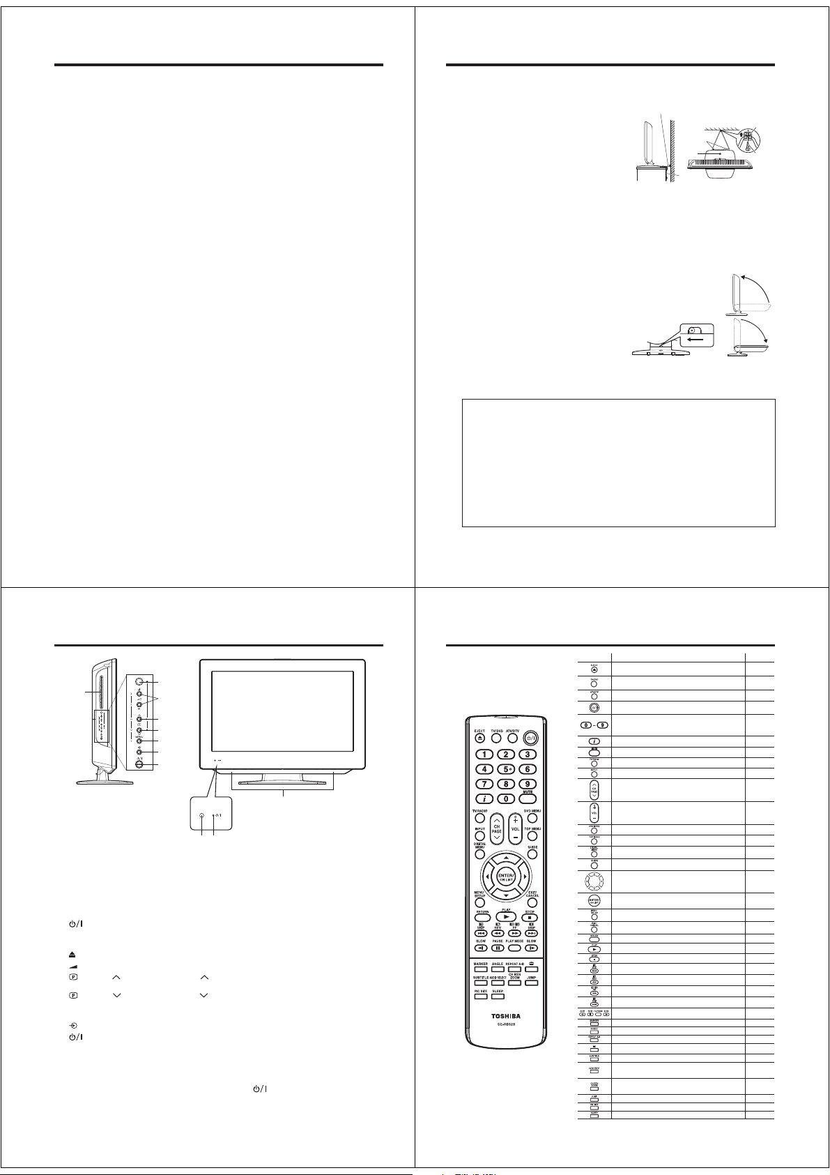
Retractable pedestal stand and locating the LCD TV
Observe the following safety precautions:
1) Ensure that unpacking and transfer of the unit is carried out by two or more people.
2) Put the LCD TV on a large level area in a recumbent posture.
3) Grab the pedestal stand and lift the display up. Confirm the pivot is locked.
4) Place the TV on a sturdy, level surface that can support the weight of the TV.
5) Be sure to secure the TV to a wall stud, pillar, surface, or other immovable structure. To
secure the TV in this manner: (1) attach a clip to an immovable structure, then (2) pass
a sturdy strap through the clip and attach each end to the hooks located at the back of
the TV. Be sure to leave at least 10 cm between the TV and the wall or similar structure
.
for ventilation
To fold the pedestal stand
1) Slide the lever on the back side of the pedestal
stand to the left.
2) Lay the display down.
NOTE: Do not operate the LCD TV when the pedestal stand is folded. The pedestal stand should not be
folded at any time except for packing purposes.
Please take note
EXCLUSION CLAUSE
Toshiba shall under no circumstances be liable for loss and/or damage to the product caused by:
i) fire;
ii) earthquake;
iii) accidental damage;
iv) intentional misuse of the product;
v) use of the product in improper conditions;
vi) loss and/or damage caused to the product whilst in the possession of a third party;
vii) any damage or loss caused as a result of the owner’s failure and/or neglect to follow the instructions
set out in the owner’s manual;
viii) any loss or damage caused directly as a result of misuse or malfunction of the product when used
simultaneously with associated equipment;
Furthermore, under no circumstances shall Toshiba be liable for any consequential loss and/or damage
including but not limited to the following, loss of profit, interruption of business, the loss of recorded data
whether caused during normal operation or misuse of the product.
If stationary images generated by text services, channel identification logos, computer displays, video
games, on screen menus, etc. are left on the television screen for any length of time they could become
conspicuous, it is always advisable to reduce both the brightness and contrast settings.
Sturdy tie (as short as possible)
Screw
hole
Slide the lever to the left
Back side of the pedestal stand
Clip
Hooks
Screw
Band
Top ViewSide View
5
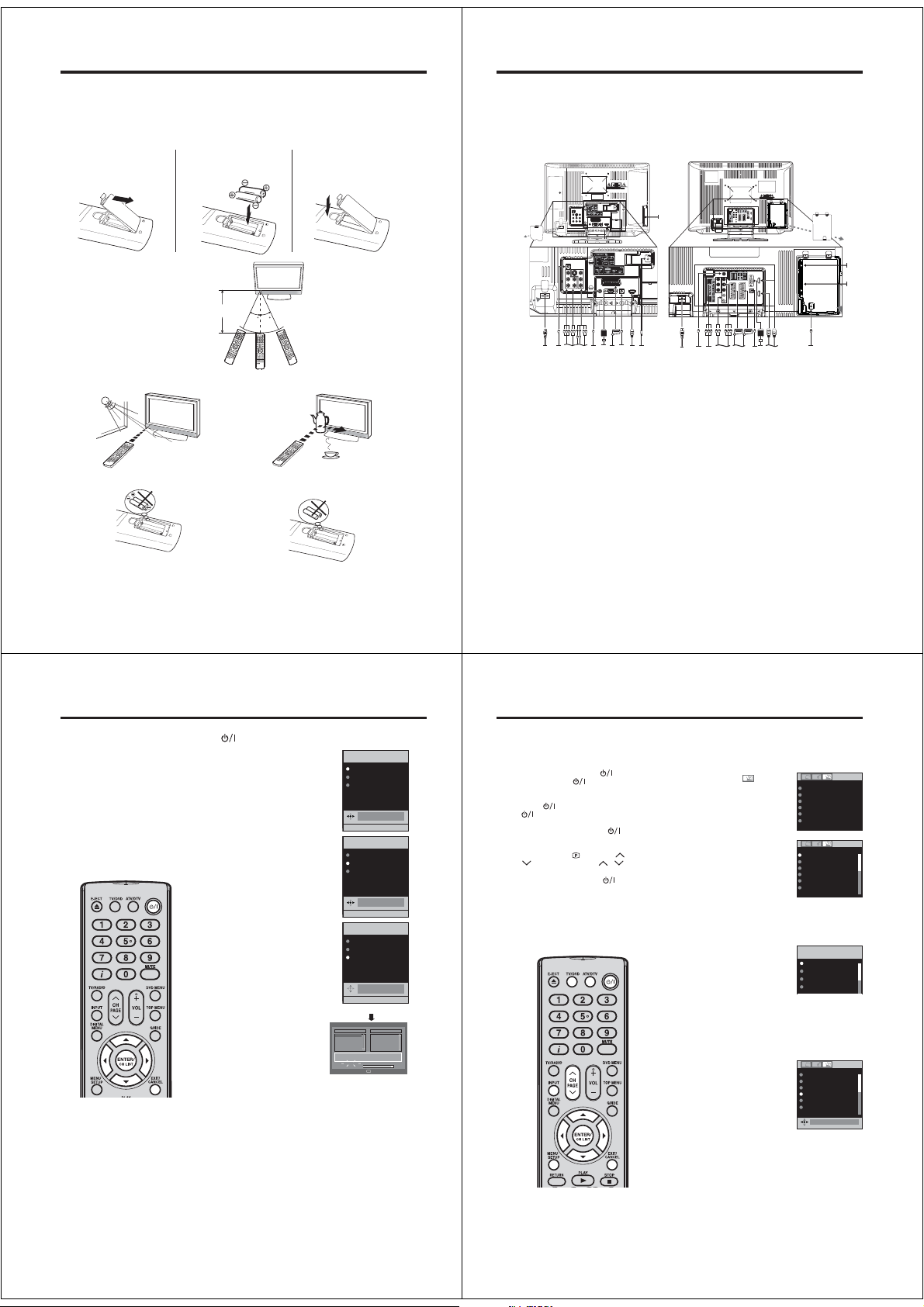
Location of controls
Disc slot
Adjusting the angle of the base (except 26DV615DG)
You can adjust the angle of the TV-screen for 3° forward or for 10° backward from vertical angle.
Hold the base of the TV while adjusting the angle.
Description of Indicators and Controls
1. Remote sensor
2.
(Power) indicator: The LED indicator lights up red in standby mode, orange in standby mode
when the timer is activated, and green in the power ON mode.
3. Loudspeakers
4.
(EJECT): Eject a disc.
5.
(Volume) +/– buttons / In Menu: Setting.
(Channel) /PLAY () button: Press to change to a higher numbered channel set into
6.
memory. DVD mode : Playback. In Menu: Setting. In Standby: Turning on the unit.
7.
(Channel) /STOP () button: Press to change to a lower numbered channel set into
memory. DVD mode : Stop. In Menu: Setting. In Standby: Turning on the unit.
8. MENU button: To display the analogue menu screen.
9.
(INPUT SELECT) button: Select input mode. In Menu : Using as ENTER button.
10.
(TV) button: Preparation: Connect power-cable to 230V/50Hz.
a) If standby-LED is red, you may turn-off. To turn-off, press TV button 1x and release.
For confirmation, standby-LED will turn off.
b) If standby-LED is off, you may turn-on. To turn-on, press TV button 1x and release.
For confirmation, standby-LED will change to red and about 1 second later to green.
c) If the TV is currently working, press TV button 1x and release to turn-off.
For confirmation, standby-LED will turn off.
In TV-off-condition, the unit cannot be turned-on by pressing
In TV-off-condition, the TV’s power-consumption is approx. 1 Watt.
If total disconnection from the mains power is required, please unplug the mains lead.
6
4
5
6
7
8
9
10
3
2
1
on the remote control.
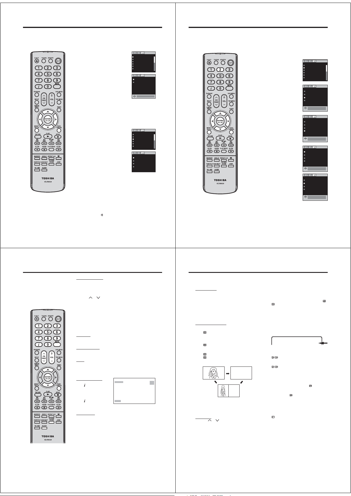
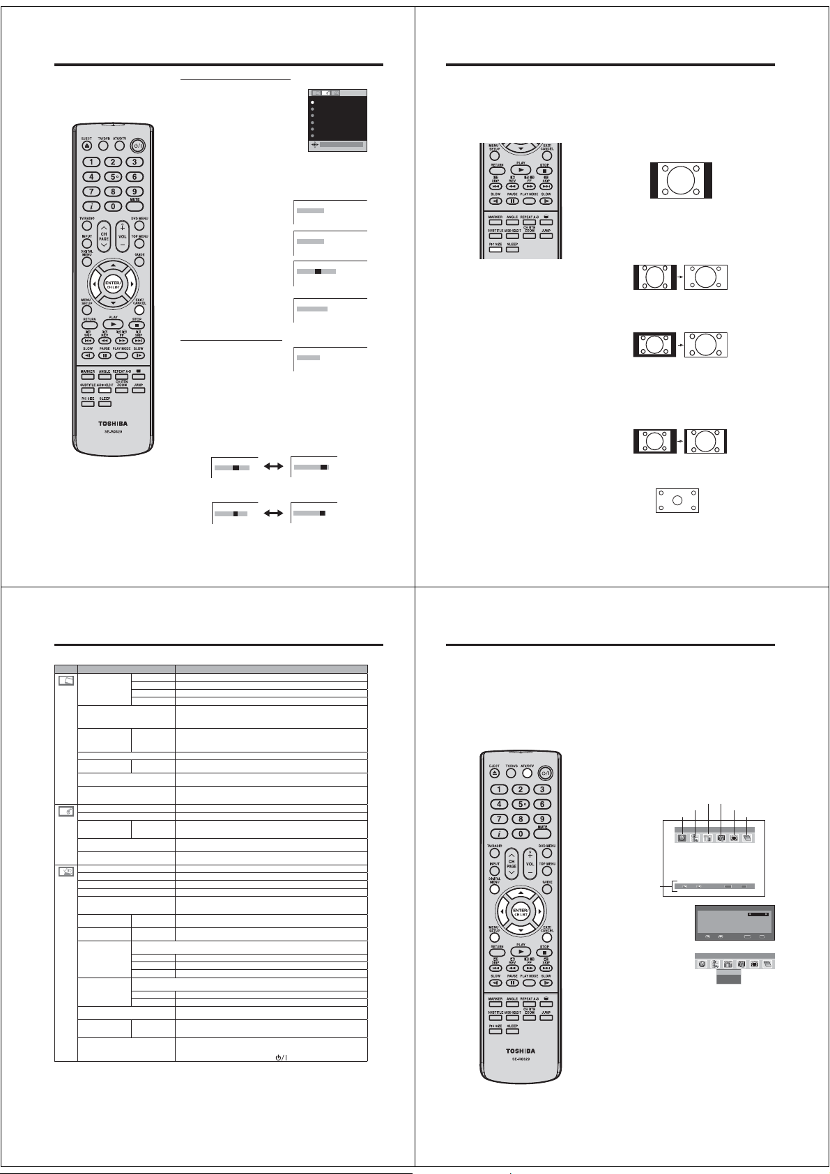
Remote Control
Function Page
Eject a disc 33
Select to operate TV/DVD 11, 32
Switches between the analogue TV and the digital TV 11, 20
Enter standby mode or turn on the power 10
Select channel
Select Teletext page
Enter password
Activate the channel organizer function
Display program position number
Teletext time display
Turn the sound on/off 14
Toggle between the TV and radio mode 27
Select an input source 11
Change the TV channel or Teletext page up or down
In Standby: Turn on the power
Volume 14
Select menu of a DVD disc 38
Select title of a DVD disc 38
Activate the digital menu 20
Display the EPG (Electronic Progr. Guide) 29, 30
Cursor buttons 10
Memorize
Teletext page 100
CH LIST
Call Setup menu
Activate the analogue menu
Exit the menu screen
Cancel marking
Remove DVD set up menu 47, 51
Play 32
Stop 32
Hold the text page
Skip chapter to reverse direction
Reveal quiz page answers
Review playpack
Sub page selection
Forward playback
Teletext enlargement
Skip chapter to forward direction
Fastext/TOPtext buttons
DVD control buttons
Marking desired scene 36
Change playback angle of a DVD disc 38
Repeat playback between A and B (DVD/CD) 37
Teletext ON/OFF
Start Digital Service
Display the subtitle 28, 39
Select between the available broadcast audio
Display the multi audio menu
Change sound track language of DVD
Switches between the present channel and the last
selected channel
Zoom (for DVD playback)
Locating desired scene 35
Select picture format 17
Sleep Timer 14
14
15
25, 50
22
14, 27, 29, 39
14, 15
11
10
15
14
47
11
11
36
15
34
15
34
15
34
15
34
15
34, 37
15
28
16
28
39
14
35
7
Page 7
Remote Control
Install the batteries
Use batteries type UM4/R03 (AAA-Size).
Do not use old or weak batteries. The remote control may not work properly with a weak voltage from such
batteries. Replace exhausted batteries with new ones. Never try to recharge normal batteries - this could
cause an explosion.
Note:
Exhausted batteries can leak corrosive electrolyte, which may cause damage to the remote control therefore remove exhausted batteries immediately.
Open the battery
1
compartment.
Install the batteries as shown
2
below, ensuring the correct
polarity.
Close the battery
3
compartment.
Aerial connection
Note: Before you connect other appliances:
To avoid potentially damaging your set, make sure all items are switched off and disconnected from the
•
mains power when you make the connections.
Arrange the desired connection.
•
When you have finished making the connections, reconnect the mains power to the unit and switch it
•
back on.
Connect your aerial as shown below. Connections to other equipment is explained further on
pages 53~57. If you have problems with reception, consult a specialist of aerial.
Illustration of 19DV615DG/19DV616DG/22DV615DG/22DV616DG
(L)
(M)
(K)
Illustration of 26DV615DG
(L)
(M)
ANT.
Distance of Remote Control Operation
Remote sensor
Maximum distance approx. 5m
Transmitter window
30 30
Point the remote control
directly at the remote sensor.
The remote control handset will not work properly in the following cases:
If bright sunlight directly beams onto the unit front. If an obstacle is placed between the unit and the
If the batteries have not been installed according to
their polarities.
handset.
Z
If the batteries are weak.
Z
Z
Z
Z
Z
8
Auto setup
Your unit has an Automatic
installation which makes installation
in your unit easy. When you turn
on the unit for the first time, the
Automatic installation routine is
activated. Using this routine, you
can select the on-screen language
and automatically search for and
store all the receivable analogue
and digital (DVB) channels.
The Automatic station presetting
feature is for the set’s built-in tuner
only. If you have a device such as
a digital decoder (eg. Satellite or
Digital Terrestrial) connected (see
page 55), you would need to tune it
in separately according to its own
instructions.
Note:
•
To cancel the Auto Tuning, press
EXIT during the process.
•
If on the “AUTO INSTALLATION
COUNTRY” screen “UK” is selected,
“Change No.” and “Move To” cannot
be used in UK (see page 23).
THE AUTOMATIC TUNING PROCESS
WILL ONLY START BY ITSELF THE
FIRST TIME YOU SWITCH THE SET
ON. HOWEVER YOU CAN RESTART
THIS PROCESS VIA THE MENU
SYSTEM (see page 12 for analogue
channels, and page 20 for digital
channels).
10
Preparation:
Press
on the unit.
AUTO INSTALLATION menu will
1
appear.
Press or to select LANGUAGE,
then press ENTER. Press or to
select desired language.
Then press ENTER.
Press or to select COUNTRY,
2
then press ENTER.
Press or to select your country.
Then press ENTER.
Press or to select AUTO
3
TUNING, then press ENTER.
The confirmation screen will be
displayed. Press ENTER to start
automatic tuning.
Your TV will now automatically tune
in all available channels.
Your TV will tune the analogue
channels first, then tune the digital
channels.
Note:
Please be patient - the Auto
•
Tuning process can take
several minutes to complete.
When the programme on the
screen stops changing and the
sound comes on, the search
process is complete.
EXIT : END MENU: RETURN
EXIT : END MENU: RETURN
EXIT : END MENU: RETURN
(ANALOGUE)
Auto Scan
TV
001 BBC ONE
002 BBC TWO
007 BBC THREE
Carrier :1
Frequency (kHz) :562000
Searching...
Progress
AUTO INSTALLATION
LANGUAGE
COUNTRY
AUTO TUNING
ENGLISH
AUTO INSTALLATION
LANGUAGE
COUNTRY
AUTO TUNING
GERMANY
AUTO INSTALLATION
LANGUAGE
COUNTRY
AUTO TUNING
AUTO TUNING
10 %
DVB-T 16QAM
:003
Radio
070 BBC Radio 1
Exit
(DIGITAL)
ENGLISH
GERMANY
ENGLISH
GERMANY
ENGLISH
GERMANY
(B)
(K)
ANT.
(A) (B) (C) (D) (E) (F)(G)(H) (I) (J)
(A)
Power supply: Connect the supplied power cable to an AC 220-240V/50Hz mains power supply only - do
not attempt to connect it to any other type of supply. Never try to repair a damaged AC power cord with
isolation-tape - this should be repaired by a specialist or rep laced. Do not let your pet loose near the cable.
Animals biting into the cable could receive a fatal electric shock, and could cause a hazard to others.
(B) HEADPHONE jack: Plug headphones with a mini plug (3.5 mm) into this jack.
(C) COMPONENT input: See page 57.
(D) AV2 input: Input for analogue A/V-Signal (Composite or S-Video). See page 56.
(E) Digital audio output: Digital output for CD/DVD & DVB-T (see page 56).
(F) PC MONITOR input (PC): See page 53.
(G) Scart socket (AV1): For the connection of scart cable. See pages 55~56.
(H) PC/HDMI AUDIO input: See pages 53, 54.
(I) HDMI input : See page 54.
(J) Aerial input socket: Connect the outdoor aerial to the aerial input socket as shown.
(K) C.I. slot: The Common Interface allows you to insert CAM (Conditional Access Module) and a suitable
Smart Card to give you access to additional Pay-TV ser vices. (See page 26) Before inserting the
module, make sure to turn off the main power and then insert the module all the way into the slot until it
is flushed with the side panel buttons.
(L) Bracket holes: Fix a wall mounting bracket (not supplied) here.
(M)
INPUT cover: When you access the input jacks, remove this cover (except 22DV615DG/22DV616DG).
(N) AV3 input: Input for analogue A/V-Signal (Composite). See page 56.
(O) Scart socket (AV1/AV2): For the connection of scart cable. See pages 55~56.
(P) HDMI1/HDMI2 input : See page 54.
(A) (E) (N) (C) (O) (H)(F)(P) (J)
9
Quick guide for ANALOG MENU operation/Selecting the
video input source/On-screen Language Selection
Make sure the aerial connection and
power supply are connected as per
the description on previous page.
Preparations:
Turn on the unit with the
•
on the unit. The
will light up in green.
To change the unit to standby mode,
press
(Power) indicator will change
from green to red. To turn on the unit
from standby mode, press
remote control again.
In standby mode, you can also turn
the unit on with
on the unit or PAGE / on
the remote control.
To turn off the unit press
on the unit - to completely switch
it off, disconnect the mains power
supply.
Press TV/DVD to select the TV mode.
•
Press ATV/DTV to select the
•
analogue TV mode.
:001
(Power) indicator
on the remote control.
(Channel) or
Quick guide for ANALOG MENU operation
Call ANALOG MENU and for example: Select AUTO TUNING.
Press INPUT.
1
button
Select ATV. Press MENU.
2
Press or to select .
on the
Press or to select AUTO
3
TUNING, then press ENTER to
enter the AUTO TUNING menu.
button
... on the following pages the MENU
can be called in the same way as
here.
4
Press EXIT to return to the normal screen.
Selecting the video input source
Press INPUT to view a signal from
another device connected to your TV,
such as a VCR or DVD player. You can
select each input source depending on
which input jacks you used to connect
your devices.
To select the video input source, press
/. Then press ENTER within 6 seconds.
•
You can return to ATV mode by pressing a numbered button
even if you switched to external input mode from DTV mode.
AUTO TUNING
MANUAL TUNING
CH ALLOCATION
LANGUAGE
ENGLISH
VERTICAL POSITION 0
AUTO 4:3 DEFAULT
AUTO TUNING
MANUAL TUNING
CH ALLOCATION
LANGUAGE
ENGLISH
VERTICAL POSITION 0
AUTO 4:3 DEFAULT
INPUT SELECT
ATV
DTV
AV1
AV2
4:3
4:3
On-screen Language Selection
Select LANGUAGE (unless you
1
Note:
If no buttons are pressed for more
•
than approx. 60 seconds, the MENU
disappears automatically.
have already selected when the set
was first switched on).
Then press ENTER.
Press or to select the desired language.
2
Press EXIT to return to the normal screen.
3
AUTO TUNING
MANUAL TUNING
CH ALLOCATION
LANGUAGE
ENGLISH
VERTICAL POSITION 0
AUTO 4:3 DEFAULT
ENGLISH
4:3
11
Page 8
Automatic station presetting with the built-in Tuner/
Changing the order of stored channels
Automatic station presetting with the built-in Tuner
Perform this feature to search for and store new analogue TV
programmes after the Automatic installation. (see page 10)
Preparation:
Make sure your antenna is connected to the aerial input (see
page 9). Select ATV (see page 11). Then press MENU.
Select AUTO TUNING, then press
1
ENTER.
Select COUNTRY, then press ENTER.
2
Press or to select your country,
then press ENTER.
Select START. Then press ENTER.
3
The automatic tuning will search for available broadcasts
and should store the channels in the correct order. During
the search the sound is muted. When all programs have
been stored, the normal TV screen will appear.
Changing the order of stored channels
The Automatic station presetting stores the stations in a specific
order. However, this order can be changed if you wish.
Select CH ALLOCATION.
1
Then press ENTER.
Select desired option, then press
2
ENTER.
After setting the each option, press MENU to return to CH
3
ALLOCATION menu.
Press EXIT to return to the normal screen.
4
Description about the each setting option:
SORT: Press or to select the channel that you want to
move, then press ENTER.
Note:
•
To restart digital auto tuning, see
page 20.
•
When the COUNTRY is set to UK,
the automatic tuning will search for
UHF broad-casts only.
When changing the order of the
•
channels, it is best to start with Ch1.
12
Press or to select the position that you want to move the
channel to, then press ENTER.
ERASE PROGRAM: Press or to select the channel that you
want to erase, then press ENTER.
SKIP: Press or to select the channel that you want to skip,
then press ENTER.
CH LABEL: Press or to select channel that you want to
rename, then press ENTER. Press or to select character,
then press or . The cursor will move to the next position.
Press ENTER to set the channel label.
mark will appear.
AUTO TUNING
MANUAL TUNING
CH ALLOCATION
ENGLISH
LANGUAGE
VERTICAL POSITION 0
AUTO 4:3 DEFAULT
COUNTRY
START
UK
AUTO TUNING
MANUAL TUNING
CH ALLOCATION
LANGUAGE
ENGLISH
VERTICAL POSITION 0
AUTO 4:3 DEFAULT
SORT
ERASE PROGRAM
SKIP
CH LABEL
Manual TV station presetting
If you like, you may manually tune a certain station into a selected program position, without
deleting or modifying program position’s contents. Example: Store the BBC 2 into program
position 2.
Preparation: connect aerial cable. Select program position
1
2. Press 2 (see page 14). OSD will indicate “2” in right upper
corner. Eventually recently stored TV-channel’s name might
also appear.
Press MENU. Press or to select
2
tool-page (see right). Press or
4:3
UK
4:3
Note:
•
Usually fine tuning is not necessary,
due to tuning’s automatically
stopping at the very best position. If
you fine-tune anyway, proper working
of teletext-reception with built-in
tuner is no longer guaranteed.
to select MANUAL TUNING.
Press ENTER.
Press or to select COLOUR
3
SYSTEM, then press ENTER.
Press or to select AUTO,
PAL or SECAM, then press
ENTER.
Please note that PAL should be
selected for use in UK.
Press or to select SOUND
4
SYSTEM, then press ENTER.
Press or to select AUTO, B/G, I,
D/K or L/L’, then press ENTER.
Press or to select SEARCH.
5
Press ENTER. Press or ,
to start tuning. Tuning will stop
automatically at next available
station. If this does not happen to
be the BBC 2, press or again to
continue tuning for the BBC 2.
Then press ENTER.
If you like to use fine-tuning, select
6
FINE and press ENTER. Press or
to fine tune. See the note on this
page.
To store other stations in additional memory-cells, repeat
7
steps 1 to 6.
Press EXIT to return to the normal screen.
8
AUTO TUNING
MANUAL TUNING
CH ALLOCATION
LANGUAGE
ENGLISH
VERTICAL POSITION 0
AUTO 4:3 DEFAULT
SEARCH
FINE 168.30MHz
COLOUR SYSTEM
SOUND SYSTEM
BBC1 168.30MHz
AUTO
SEARCH
FINE 168.30MHz
COLOUR SYSTEM
SOUND SYSTEM
BBC1 168.30MHz
AUTO
SEARCH
FINE 168.30MHz
COLOUR SYSTEM
SOUND SYSTEM
BBC1 168.30MHz
SEARCH
FINE 175.30MHz
COLOUR SYSTEM
SOUND SYSTEM
BBC1 175.30MHz
4:3
AUTO
AUTO
AUTO
AUTO
AUTO
AUTO
AUTO
AUTO
13
Basic Operation
Note:
If the built-in tuner does not receive
•
anything (e.g. if no antenna is
connected) during TV-operation, then
the TV-unit will change to standby
after approx. 15 minutes.
14
Channel selection
With the numbered buttons.
Example:
No. 2: Press 0 and within 2 seconds, press 2.
•
•
No. 29: Press 2 and within 2 seconds, press 9.
Press CH
or to change up or down a channel. This takes
approx. 2 seconds. If the auto search only stored 5 stations,
only these 5 will appear. Skipped channels will not appear (see
page12).
The CH LIST shows a list of all receivable programmes.
They are located in channels 1 to 99.
Press CH LIST to display the CH LIST.
Press or to select the desired channel.
Press CH LIST to display the selected channel. Press EXIT to
exit.
QuickView
button allows you to go back to the last selected
CH RTN
channel.
Volume adjusting
Press VOL + or – to adjust the volume. The volume level
indicator disappears after 4 seconds.
MUTE
Press MUTE. The sound will be cut off. MUTE will appear for
approx. 4 seconds.
The muting can be released by pressing MUTE again or VOL +
or –.
Information display
In the analogue TV mode:
Press
. Channel number
and picture size setting
will appear for approx. 4
seconds.
In the digital TV mode:
Press
. The program
information will appear (see
‘Channel banner’ on page 27).
SLEEP TIMER
To set the sleep timer press SLEEP. SLEEP and the minutes will
appear. Each time you press SLEEP, the SLEEP time shown
will change in the order of 120, 110, 100, 90, 80, 70, 60, 50,
40, 30, 20, 10, 0. When the displayed time runs out, the unit
will switch to standby. The display will disappear after approx. 4
seconds.
To cancel the sleep timer:
Press SLEEP repeatedly until ‘0’ appears.
STEREO 1
ARD
AUTO
Teletext
Teletext is sent page by page. This unit is able to automatically store up to 256 pages, but they can only be
accessed once they have been stored. This can take a few moments.
Fastext/TOPtext
The Fastext/TOPtext is teletext with a special
directory.
On the lower part of the screen there are four
different coloured fields (red, green, yellow and
blue). These fields lead directly to the pages
shown within. The coloured buttons on the remote
control correspond to the coloured fields. Press the
appropriate coloured button in order to activate the
desired colour field.
Switch on / off Teletext
Teletext is not transmitted by all channels.
Select a channel that shows teletext.
. You will now see a teletext page. (If
Press
“100” is shown without any text information, it
may mean that the channel you have selected
does not support teletext.)
Press
again. The TV-screen will be split into
two and both Teletext information and actual
broadcast will be displayed at the same time.
Press again in order to switch off teletext.
Press again in order to switch on teletext again.
The last page which was stored is now shown.
TELETEXT
TELETEXT
Note:
You cannot select any other channels as long as
•
teletext is switched on. Switch teletext off when
you want to switch over to another channel.
Select Page
Press CH
or until the page you desire
appears. Or ... enter the requested page number by
using the 10 Number Buttons.
And if you mistype something, just enter the complete 3-digit wrong page number then enter the desired number again. Or ... press one of the coloured
teletext buttons so that a page from Fastext/TOPtext
is shown.
Hold Pages
Some pages are divided up into subpages by the
channel.
Subpages are automatically shown in turn, as they
are transmitted. In order to hold the page, press
Press
again in order to display the next subpage.
Directly Select Subpages
You can directly select the subpages if required.
Example:
Page 128 from Teletext comprises of 2 subpages. In
the right upper corner you will, for example, see 1/2.
That means that page one of 2 subpages is being
shown at the moment.
128 128 CEEFAX 21.07.03 15:01:38
Press in order to select subpage 2. 4 dashes
(----) are shown. Enter 0 0 0 2. It can take a minute
before subpage 0002 appears.
Press
again in order to switch off the subpage
feature.
You can only select other teletext pages when the
subpage feature is switched off.
Enlargement
In order to enlarge the display, press
Either the upper or lower half of the screen is
enlarged.
Each time you press
display of the upper or lower half of the screen or
the full picture.
Answering Quiz Questions
Some pages contain quiz questions with concealed
answers.
Press
in order to show the answers.
Page 100
Press ENTER in order to show page 100.
you switch between the
1/2
.
.
15
Page 9
Stereo reception with the built-in analogue tuner
The built-in Tuner can detect and
receive NICAM stereo broadcasts
automatically.
Note:
In case of bad reception, the stereo
•
sound also can be disturbed.
16
NICAM stereo sound reception:
Select NICAM, then press ENTER.
1
Press or to select AUTO or OFF.
Select OFF if you do not want to
receive NICAM sound.
Press EXIT to return to the normal screen.
2
The following types of broadcast are possible with
NICAM transmissions
‘NICAM ST’ illuminates for approx.
4 seconds when a NICAM STEREO
broadcast signal is received.
‘NICAM M1’ illuminates for approx.
4 seconds when a NICAM MONO A
broadcast signal is received.
‘NICAM M1/M2’ illuminates for
approx. 4 seconds when a NICAM
MONO A and MONO B broadcast
signal is received.
This will be displayed for approx.
4 seconds if a NICAM signal is
received when the ‘NICAM OFF’
option is selected.
Stereo reception in Germany
‘STEREO’ illuminates for approx. 4
seconds when a STEREO broadcast
signal is received.
When 2-channel sound reception is available, you can
select your preferred audio with the AUDIO SELECT
button.
Each time you press AUDIO SELECT, the sound channel will
switch to the alternative channel available.
NICAM 2-channel sound reception (not available in
Germany)
NICAM M1/M2
NICAM AUTO
BASS 25
TREBLE 25
BALANCE 0
SURROUND OFF
HDMI1 AUDIOHDMI
NICAM ST
NICAM M1
NICAM M1 / M2
NICAM OFF
STEREO
NICAM M1/M2
2-channel sound reception in Germany
SOUND 1 / 2
SOUND 1 / 2
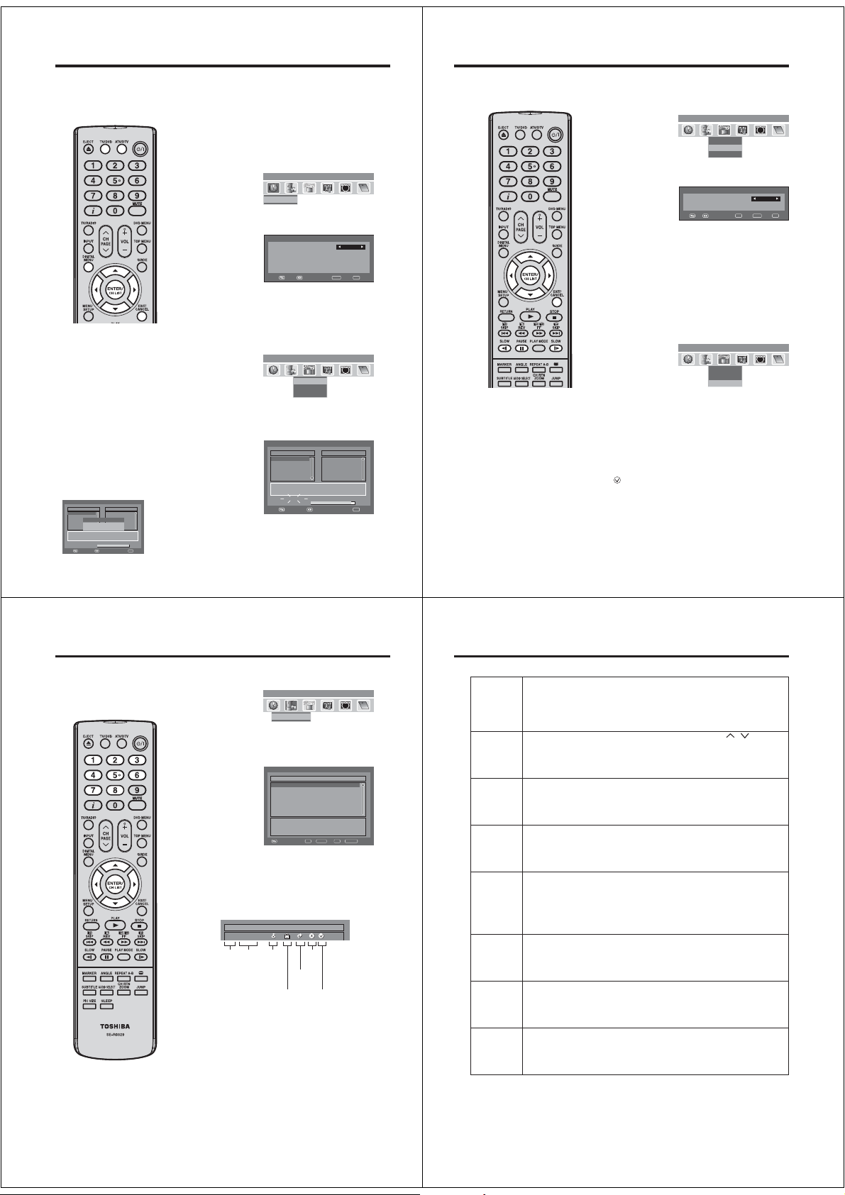
Picture format
The broadcaster may transmit a Wide Screen Signalling (WSS) signal which can determine the correct
picture width and set it automatically when the AUTO setting is used. If you want to change this setting, you
can select from the formats listed below.
AUTO
Press PIC SIZE repeatedly until AUTO
AUTO
appears.
Notes:
•
When the PICTURE SIZE is set
to AUTO, the aspect ratio will
automatically change according
to the Wide Screen Signalling
(WSS) signal, if it is available. This
may be either transmitted by the
broadcasting TV channel, or via a
recording from a VCR etc. Any WSS
signal received will only be effective
in the AUTO mode - however, some
DVD players / Digital Decoders etc.
will automatically switch the aspect
ratio via the SCART input (Pin 8
switching), even if AUTO is not
selected.
In any case if you want to change
to a different aspect ratio to the one
selected automatically, you can
change it by pressing PIC SIZE.
•
In PC mode, the PICTURE SIZE
feature is available only for 16:9 or
4:3 format.
•
In HDMI or COMPONENT mode of
scanning rate: 720p and 1080i, the
PICTURE SIZE feature is available
only for 16:9 or REAL (HDMI only)
format.
•
Using the special functions to change
the size of the displayed image (i.e.
changing the height/width ratio) for
the purposes of public display or
commercial gain may infringe on
copyright laws.
Manual format setting
Pressing PIC SIZE repeatedly scrolls through the following
options.
4:3
This mode shows a 4:3 picture in its original size and shape with
vertical bands on the left and right side.
16:9
This mode is used with 16:9 signals from a Digital decoder, DVD
player or other external source. This uniformly stretches a 4:3
image horizontally to fill the screen (For example, a 16:9 image
is often stored “anamorphically” on a DVD, where the 16:9
image is stored as a horizontally compressed 4:3 image - this
mode restores the image to its correct 16:9 proportions).
CINEMA:
This mode is used to zoom-in on (expand) 4:3 ‘letterbox’ format
pictures (with black bars at the top and bottom) so that they fill
more of the screen.
Note:
• In the CINEMA mode, part of the picture may be slightly cut
off due to the expansion. However, it is possible to scroll the
picture up or down to view the top or bottom part of the picture
(see page 18).
14:9
This enlarges a 4:3 picture to the 14:9 format.
(16:9)
(CINEMA)
(14:9)
REAL (HDMI mode only)
The picture is displayed with original size.
17
Other convenience functions
You can change the default settings to convenience use.
Icon Selected Items Setup hint
PICTURE
PREFERENCE
BRIGHTNESS / CONTRAST / COLOUR /
TINT(NTSC) / SHARPNESS
DNR*
(26DV615DG)
COLOUR TEMPERATURE Bluish (COOL) / Neutral (MEDIUM) / Reddish (WARM)
BLUE BACK ON / OFF You can set the TV to automatically change to a blue screen and mute the sound if
BACKLIGHT You can use the Back light feature to adjust the screen brightness for improved
RESET Select “RESET” to reset PICTURE PREFERENCE, BRIGHTNESS, CONTRAST,
NICAM See page 16.
BASS / TREBLE / BALANCE You can adjust the sound quality to your preference.
SURROUND
(26DV615DG)
HDMI AUDIO (19/22DV615/616DG)/
HDMI1 AUDIO (26DV615DG)
RESET Select “RESET” to reset BASS, TREBLE and BALANCE to the factory preset
AUTO TUNING See page 12.
MANUAL TUNING See page 13.
CH ALLOCATION See page 12.
LANGUAGE See page 11.
VERTICAL POSITION When the CINEMA mode is selected (see page 17), you can adjust the vertical
AUTO 4:3 DEFAULT
SLEEP TIMER 0~120 min(every
AV1 INPUT/
AV2 INPUT
(26DV615DG)
AV1 OUTPUT
(19/22DV615/616DG)
AV COLOUR
REC SCREEN
STATUS
RESET TV SETTING Press ENTER to enter the RESET TV SETTING screen.
Note:
*1
In HDMI or COMPONENT (except 480i/576i) mode, the DNR option cannot be selected.
*1
The interferences from the input are suppressed most if HIGH is set. This could result in side-effects such as loss of sharpness and
smearing.
*2
AUTO 4:3 DEFAULT is available only for AUTO picture size setting.
*2
In COMPONENT mode, AUTO 4:3 DEFAULT is available only for 480i/576i mode.
*3
PAL is the colour system used in Germany. NTSC 3.58 is used in the USA, PAL 60 used in Germany handled video recorders, which
play NTSC video tape recording.
If the picture shows horizontal stripes, set to AUTO.
18
SPORTS Bright and dynamic picture (factory-set)
STANDARD Standard picture quality (factory-set)
MOVIE Movie-like picture setting (factory-set)
MEMORY Your personal preferences
1
OFF / LO W /
MEDIUM / HIGH
ON / OFF The SURROUND feature processes the audio signal to expand the listening field
*2
4:3 / 16:9 This option selects the default way that a 4:3 signal is shown - either as normal
10 minutes)
Selecting the “AV1 INPUT” or “AV2 INPUT” type - this ensures that the TV processes the
input signal correctly. Press or to select AV, S-VIDEO or RGB.
AV Composite signal (e.g. from a video recorder).
S-VIDEO S-Video signal (e.g. from DVD player with S-Video output).
RGB RGB signal (e.g. from DVD player with RGB output).
This determines whether the AV1 outputs the signal from the internal tuner or whatever input is shown
on the screen.
TV Outputs the last channel position selected.
MONITOR The picture displayed on TV-screen.
*3
ON / OFF This function is used in conjunction with the Timer function that is included as part
You can adjust the picture to your preference.
The “TINT(NTSC)” option can be selected if an NTSC 3.58MHz or NTSC 4.43MHz
signal is input through one of the AV sockets, and NTSC or AUTO has been
selected for the AV COLOUR option.
Sometimes it is not possible to input a high-quality HD signal. The actual signal
input is too small and noisy, e.g. a video film in letterbox format, or a noisy analogue
cable TV signal. DNR can slightly reduce interferences caused by the faulty input
signal.
the signal is weak or absent.
picture clarity.
COLOUR, TINT(NTSC), SHARPNESS, COLOUR TEMPERATURE and
BACKLIGHT to the factory preset values.
wider and deeper to create a ‘pseudo surround-sound’ from the TV’s speakers. The
feature works with stereo signals from TV broadcast or AV input.
See page 54.
values.
picture position. Press or to adjust the vertical position of the picture by up to
+10 and downwards by up to -10.
“4:3” or expanded in the “16:9” mode, according to your preferences.
You can set SLEEP TIMER to automatically turn off the TV. To cancel the SLEEP
TIMER, set to “0”.
The AV Colour setting only applies when viewing devices connected to the AV
inputs.
of the Digital EPG. It determines whether the TV screen switches on or not when a
programmed Timer setting begins - see page 30 for further details.
Press or to select “YES”, then press ENTER.
Reset the TV function will now begin, and this unit will automatically turn off. As the
power is not automatically turned on, press
to watch TV.
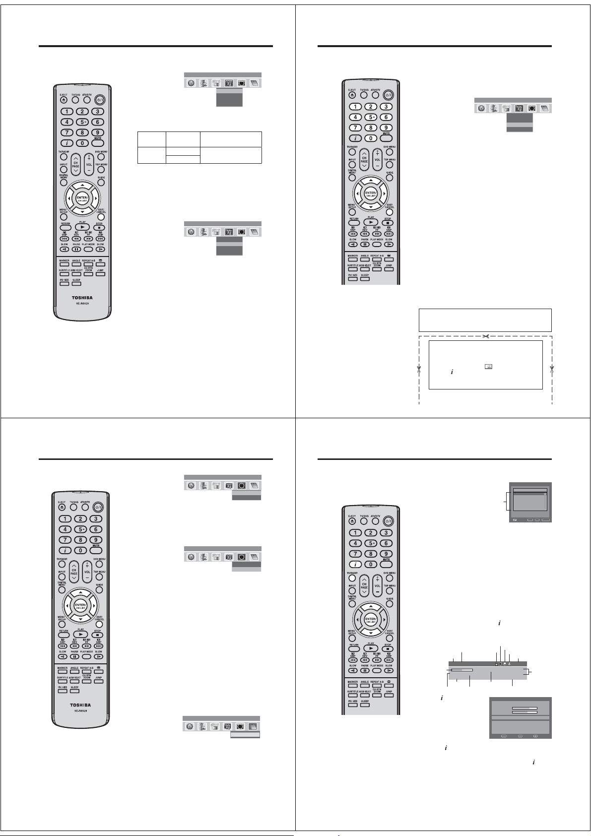
Guide to using the Digital Menu system
When the set is in the digital mode, you can access the main menu by pressing DIGTAL MENU on
the remote control. This main menu contains several options,
- Language Setup
- Channel Organizer
- Installation
- System Configuration
- Technical Information
- Common Interface
The main menu is the gateway for all the other ‘sub’ menus. You can navigate between the different
options in the main menu by pressing or .
The DIGITAL MENU button will also function like an ‘EXIT’ button, i.e. when any menu is active,
pressing the DIGITAL MENU button will return to the previous stage.
Preparation:
Press ATV/DTV to select the digital TV mode.
Press DIGITAL MENU to display the Main menu.
1
Press or to select desired options. (Example: selecting
the Language Setup option.)
Guide of the
available buttons
Press ENTER.
2
The selected menu will
appear.
Some of the options have a
sub menu.
Press or to select
desired sub menu, then press
ENTER.
(Example: sub menu in the
Installation option.)
When you have finished making adjustments, press EXIT to
3
return to the normal screen.
Note:
In analogue TV mode, DIGITAL MENU will not work. Please
press ATV/DTV to select digital TV mode to display the
digital menu.
However, it is possible to use the MENU in the digital TV
mode.
The analogue menu includes some general settings for this
TV that apply to both modes, and it will be displayed over
the digital TV screen.
Installation System Configuration
Channel Organizer Technical Information
Language Setup
CH1
CH2
ABC
ABC
CH3
Enter Exit
Navigate
Language Setup
Menu Language
Pref. Au
dio Language English
Pref. S
ubtitle Language
Pref. Digital Se
rvice Langua
Navigate
CH1
CH2
ABC
ABC
CH3
Auto Scan
Manual Scan
Carrier Setup
Common Interface
puteS egaugnaLunem niaM
Texd
i
i
CI
ge
Enter Exit
Texd
English
English
English
i
i
noitallatsnIunem niaM
CI
19
Page 10
Language Setup/Auto Scan
Language Setup
Preparation:
Switch on appliance. Press TV/DVD to select the TV mode, then
press ATV /D TV .
The appliance switches over to DVB-T-mode.
Menu languages supported are English, French, German,
Italian, Spanish, Russian, Portuguese, Dutch, Polish, Swedish,
Turkish, Finnish, Greek, Danish and Norwegian. (Welsh and
Gaelic are available only for Digital Service Language.)
1
2
3
Auto Scan
Preparation:
Please ensure that all the connections have been made
Note:
•
If “FINLAND” is selected on the
“AUTO INSTALLATION (COUNTRY)”
screen, two languages are displayed
for each item and the first selected
language has priority. The language
output depends on the languages
contained in the broadcast.
•
All the channels will be deleted
before the scanning process begins.
•
You can cancel the scan process
at any time by pressing EXIT. The
carriers and the services stored
before EXIT is pressed will be stored.
•
When the signal from the
broadcasting station is being
updated and you are watching a
digital broadcast, the channel will
be automatically updated. The list
of services screen will appear while
updating, and the ‘Scan completed’
message will be shown after the
update is complete.
DVB-T 16QAM
Auto Scan
:003
TV
Radio
070 BBC Radio 1
001 BBC ONE
002 BBC TWO
007 BBC THREE
Information
Scan completed
Carrier :1
Frequency (kHz) :562000
Progress
20
Navigate
:001
Exit
correctly (see page 9).
1
2
3
Press DIGITAL MENU, the menu will appear on the screen.
Press or to select Language Setup option, then press
ENTER.
Language Setup menu will appear.
Press or to select the item you want to change.
Press or to select desired language.
When all changes are decided, press EXIT to return to the
normal screen.
Press or to select ‘Auto Scan’ then press ENTER.
The confirmation banner will be displayed.
Press or to select ‘Yes’ or ‘No’, then press ENTER.
The Auto Scan process will now begin.
The scanning process will be displayed in the progress bar.
u
nem niaM
CH1
CH2
ABC
ABC
CH3
Language Setup
Language Setup
M
en
u La
nguage
Pref. Audio Language
Pref. Subtitle Language
Pref. Digital Service Lang
Navigate
unem niaM
CH1
CH2
ABC
ABC
CH3
Auto Scan
Manual Scan
Carrier Setup
Auto Scan
DVB-T 16QAM
TV
001 BBC ONE
002 BBC TWO
007 BBC THREE
Carrier :1
Frequency (kHz) :562000
Searching...
Progress
:003
uage
Radio
070 BBC Radio 1
Navigate
Texd
i
i
English
English
English
English
Enter Exit
Texd
i
i
:001
Exit
Manual Scan/ Carrier Setup
Manual Scan
With the Manual Scan option, you can tune one carrier at a time,
by entering the carrier parameters manually.
Press or to select ‘Manual Scan’, then press ENTER.
1
CH1
CH2
ABC
ABC
CH3
Auto Scan
Manual Scan
Manual Scan
Channel list
Frequen
ABC
ABC
cy (kHz)
CH1
CH2
CH3
Carrier Setup
Navigate
Auto Scan
Manual Scan
Carrier Setup
0..9
You can choose the carrier number from the Channel list by
2
puteS egaugnaL
CI
noitallatsnI
CI
Note:
•
If on the ‘AUTO INSTALLATION
COUNTRY’ screen ‘FINLAND’ is
selected, ‘Frequency (kHz)’ cannot
be used.
•
When the Country is set
to FINLAND in the ‘AUTO
INSTALLATION COUNTRY’
If there is a Channel List in the data
after Auto Scan or Manual Scan,
Channel Type Selection Menu will
be displayed and available to set
Channel List Type.
Select the Channel List Type by
pressing / and press ENTER
If “FINLAND” is selected on the
•
“AUTO INSTALLATION COUNTRY”
screen, Data is displayed on the
“Carrier Setup” screen.
using or and the corresponding frequency set for the
carrier will be set for tuning.
Otherwise you can
also directly enter
the frequency value
to start the tuning.
After setting the carrier, press ENTER to start the scanning.
3
During the scan process, the list of services (TV/Radio)
collected for the carrier will be listed.
Then the confirmation banner will be displayed.
4
Press or to select ‘Yes’ or ‘No’, then press ENTER.
Press EXIT to return to the normal screen.
5
Carrier Setup
The Carrier setup option menu lists all the carriers (multiplexes)
that are currently available and allows you to Rename, Delete or
Rescan carriers individually.
Press or to select ‘Carrier Setup’ then press ENTER.
1
All the carriers are listed with their frequency and service
2
information - the user can scroll through the carrier list and
select each one individually to Rename, Delete or Rescan.
Rename:
3
Select carrier, then press Red button. The alphanumeric
keypad will appear. You can rename a service as per your
preference (see page 23).
Delete:
Select carrier, then press Green button. The check mark
(
) will be displayed for selected carrier. Then press
ENTER. The confirmation banner will be displayed.
Press or to select ‘Yes’ or ‘No’, then press ENTER. If
the option ‘Yes’ is selected then all the marked carriers will
be deleted from the list.
Rescan:
Rescan allows to tune the already tuned carrier, to collect
any new programmes that are currently available in the
stream. Press Blue button, to rescan the current selected
carrier.
Texd
i
i
Ch-
474000
Enter Exit
Texd
i
i
noitallatsnIunem niaM
CI
21
noitallatsnIunem niaM
CI
21
Channel Organizer
The Channel Organizer feature
provides options to organise the
channels. The following options
are supported: Lock, Skip, Go To,
Delete, Rename, Move, Change No.,
Move To.
Note:
•
While in TV mode, only TV
programmes will be displayed and
only radio programmes will be
displayed while in radio mode.
The displays of Channel / Service
•
name will be abbreviated depend on
its size of the letter.
22
Press or to select ‘Channel Organizer’, then press
1
ENTER.
CH1
CH2
ABC
ABC
CH3
Channel Organizer
The Channel Organizer menu will appear. The available
2
programmes will be listed, depending on the current mode.
The selected programme will be highlighted.
To toggle within the service list, press or .
By pressing the corresponding Number Button (1-8), you
3
can activate the following functions from this menu for each
channel: Lock, Skip, Go To, Delete, Rename, Move, Change
No. and Move To. (You can deactivate each of these
functions by pressing the same number again.) See page
23 for setting details.
rezinagrO lennahC
S.No Service Name Lock Skip Del Move
671 MNO
672 PQR
673 STU
674 TCM
679 VWXYZ
800 SAT.1
672 ARTE
1. Lock 4. Delete 7. Change No.
2. Skip 5. Rename 8. Move To
3. Go To 6. Move
0..9
D.Menu TV/RadioExit
Navigate
Indications:
S.No Service Name Lock Skip Del Move
030 CBBC
Service
Service
Pay
number
name
channel
Locked
service
Skipped
service
Delete
mark
Move
mark
Channel Organizer
Setting details
rezina
grO lennahCunem niaM
Texd
i
i
CI
Lock
Skip
TV
Go To
Delete
Rename
Move
Change No. *
Move To *
Note:
* If on the “AUTO INSTALLATION(COUNTRY)” screen “UK” is selected, “Change No.” and “Move To” cannot
be used in U.K.
When the service is locked, you must enter your PIN whenever you tune to the service.
①
Press / to select the desired service.
②
Press 1 on the remote control. If you already set the PIN, enter it here. If not, enter the
factory preset PIN “0000”.
An icon displays indicating the service is locked.
•
Pressing 1 will turn the lock icon on and off. (PIN entry is required.)
③
Press DIGITAL MENU to save the setting.
Services that are set to skip will not be picked up when pressing CH
①
Press / to select the desired service.
②
Press 2 on the remote control. An icon displays indicating the service to be skipped.
••
Pressing 2 will turn the skip icon on and off.
③
Press DIGITAL MENU to save the setting.
To view services that are set to be skipped, use 0-9 or select from the Channel List.
Use this function to jump to the specific service in one step. This is useful when there are
many services displayed on screen to scroll through.
①
Press 3 on the remote control. Now you can change the service number on the left
side of the screen.
②
Enter the number using 0-9, and then press ENTER. The highlight moves to the
selected service.
Delete the selected service(s) from the memory.
①
Press / to select the desired service.
②
Press 4 on the remote control. An icon displays indicating the service to be deleted.
•
Pressing 4 will turn the delete icon on and off.
③
Press DIGITAL MENU to save the setting. A confirmation message displays.
④
Press / to select “Yes”, and then press ENTER.
Change individual service names.
①
Press / to select the desired service.
②
Press 5 on the remote control. A character set screen displays.
③
Press Yellow button to enter a new name for the service.
•
Press /// to move the cursor, then press ENTER to confirm the input of a
character.
④
Press DIGITAL MENU to save the setting. A confirmation message displays.
⑤
Press / to select “Yes”, and then press ENTER.
Sort the order of the selected service by moving the service position.
①
Press / to select the desired service.
②
Press 6 on the remote control. An icon displays indicating the service to be moved.
•
Pressing 6 will turn the move icon on and off.
③
Move the selected service to the desired position using /, and then press ENTER
to register the change.
Change service number.
①
Press C/D to select the desired service.
②
Press 7 on the remote control. Now you can change the service number on the left
side of the screen.
③
Enter the number using 0-9, and then press ENTER.
You cannot enter the same service number with other one.•
Sort the order of the selected service by modifying the service number.
①
Press / to select the desired service.
②
Press 8 on the remote control. Now you can change the service number on the left
side of the screen.
③
Enter the number using 0-9, and then press ENTER. The service moves to the new
position.
/ .
23
Page 11
Display Setup/Time Setup
Display Setup
1
2
3
Time Setup
If the time displayed on the Channel banner differs from the
actual time, it can be corrected.
1
2
3
24
Press or to select ‘Display Setup’, then press ENTER.
Main menu System Configuration
CH1
CH2
ABC
ABC
CH3
Display Setup menu will appear.
Press or to select the item you want to change.
Then you can change each setting by pressing or .
Banner
1 sec, 2 sec.….
timeout
7 sec.
Banner
Top Select whether the ser vice
position
Bottom
After all the changes are made, press EXIT to return to the
normal screen.
Select how long the service
banner information appears on
screen.
banner information appears on
top or bottom of the screen.
Display Setup
Time Setup
P
assword Setup
Subtitle
Texd
i
i
CI
Press or to select ‘Time Setup’, then press ENTER.
Main menu System Configuration
CH1
CH2
ABC
ABC
CH3
Time Setup menu will appear.
If the time displayed on the Channel banner differs from the
actual time, adjust the time offset with the or button
until the correct time is shown.
Note:
Normally, this would be done by selecting “Auto”.•
After all the changes are made, press EXIT to return to the
normal screen.
Display Setup
Time Setup
P
assword Setup
Subtitle
Texd
i
i
CI
Note:
•
There are 15 age-based ratings,
ranging from ‘4’ (years old) to ‘18’
(years old) and ‘None’. Eg. If the
Parental Lock is set to ‘8’ (years
old), only the services which have
the parental rating of ‘8’ (years old)
or under will be viewable without
entering the Password.
•
You will be prompted to enter the
password, when you set new
parental rating.
You can set the new parental rating
only when you enter the password
correctly, otherwise the old parental
code will be retained.
Password Setup (Parental lock)
Password Setup (Parental lock)
This feature allows you to have a parental control of the service
viewing as per your preference.
Once a service is protected with a password, it cannot be
viewed unless the correct password is provided.
Press or to select ‘Password Setup’, then press
1
ENTER.
‘Enter Password’ will appear. Press ‘0 0 0 0’ using the
2
Number Buttons. (This is the default password.)
Press or to select ‘Parental Lock’, then press or to
3
select desired parental rating (see note). Then press EXIT
to return to the normal screen.
You can also change the password using the next option.
4
Press or to select ‘Change password’.
Then enter your chosen new password (0 to 9), be sure to
remember this password. After you have entered the new
password for the first time, you need to enter the same
password again for confirmation. The Information banner
will then appear.
Press EXIT to return to the normal screen.
While toggling between channels, if a service which has a
parental rating is selected then you will be asked to enter the
correct password to view that channel. If the channel you are
currently watching supports a parental rating then the rating will
also be displayed in the Channel banner menu (see page 27).
IMPORTANT NOTE ON RESETTING THE PASSWORD
We suggest that you remove the following instruction from
the operating instructions to prevent children from reading it.
If you forget your password, follow steps below to
reset the password.
1. Press ATV/DTV to select the digital TV mode.
2. Press MENU to display the analogue menu, then
press or to select
3. Press
The password is reset to ‘0000’.
Main menu System Configuration
CH1
CH2
ABC
ABC
CH3
4 times within 5 seconds.
(SETUP).
Display Setup
Time Setup
P
assword Setup
Subtitle
Texd
i
i
CI
25
Version/Software Upgrade/Common Interface
Version
You can check the software and hardware versions.
Note:
Do not disconnect the AC cord when
•
the software upgrade is in progress,
as this may cause the upgrade to fail.
At this time you cannot use any of the
buttons.
When the unit searches for a software
•
upgrade signal, the message ‘Please
wait...’ will be displayed.
26
Press or to
1
select ‘Version’, then
press ENTER.
The hardware and
software versions are
displayed.
Press EXIT to return to the normal screen.
2
Software Upgrade
Software Upgrade allows you to download the latest software
available on the Engineering channel.
Manual upgrade
Press or to
1
select ‘Software
upgrade’, then press
ENTER.
If a software upgrade is available from an Over Air
2
Download (OAD) then the message ‘S/W available, do you
want to download?’ will be displayed - you can then select
‘Yes’ or ‘No’ by pressing or , then press ENTER.
If you select the option ‘Yes’ then the Software Upgrade
3
process will be initiated. It will take about 20 minutes and
after this process is complete, the TV will be rebooted
automatically.
If you select the option ‘No’ you can continue to watch TV
programmes as before.
Auto upgrade
When you tune to the service that provides the upgrade via
1
Over Air Download, a confirmation message displays.
Follow the screen prompts.
2
Common Interface
You can access the Common Interface module information from
this menu option.
Preparations
Insert CAM into the DVB Common Interface slot on the backside
of the TV (see page 9).
Press or to
1
select ‘Common
Interface’, then press
ENTER.
The CAM module name will be displayed. You have to press
2
ENTER to view further information.
In the CI Menu, CAM specific information such as Module
3
information, Smart card information, Language and
Software Download are shown.
Press or to select information, then press
ENTER to see detail.
Press EXIT to return to the normal screen.
4
Main menu Technical Information
CH1
CH2
ABC
ABC
CH3
Main menu Technical Information
CH1
CH2
ABC
ABC
CH3
CH1
CH2
ABC
ABC
CH3
Texd
i
i
Version
Software upgrade
Texd
i
i
Vers ion
Software upgrade
Texd
i
i
Common Interface
Channel list/Channel banner
Channel list
Press CH LIST to display the Channel list menu.
CI
CI
ecafretnI nommoCunem niaM
CI
Note:
•
Channel / Service names can only be
displayed up to about 16 characters
- if the name is longer than this, it will
be abbreviated. The Basic Service
Information screen (Step 2) displays
the full Channel/Service names, not
the abbreviated names.
Subtitles are displayed on the
•
channel banner. Some broadcasts
may not provide this service.
1
S.No Services
671 MNO
672 PQR
673 STU
List of the
674 TCM
services
679 VWXYZ
800 SAT.1
Select the Services:
2
List of the services present under the selected Channel
group will be displayed in the left side of the menu.
Press or to toggle within the service list, then press
ENTER.
Toggle between the list of TV and Radio services:
The TV/RADIO is used to toggle between the TV and Radio
mode. If you press CH LIST when you are in Radio mode
then the channel list menu will display the list of Radio
services. If you wish to view the list of TV services without
exiting the current menu, TV/RADIO should be pressed
once.
Channel banner
When you change from one channel to another, the Channel
banner will be displayed for the selected service. In the channel
banner menu, information such as current date & time, channel
name, etc. will be displayed.
While watching the service, press to display the Channel
1
banner at any time. It will disappear after the Banner
timeout value (this can be adjusted to your preferred value,
see page 24).
Service name
Service No.
Duration
graph
Undefined
Genre
Starting time/Ending time
of current programme
Press again to display the
2
Basic Service Information.
You can verify the signal
strength and quality of the
selected service here.
If necessary, adjust the
direction of the antenna
to obtain the maximum
signal strength.
•
When the Country setting has been set to FINLAND,
once more to display the advanced detailed
press
information.
To remove the Channel banner immediately, press
3
DVB Teletext available
DVB Subtitle available
Lock status
Pay TV
Audio mode
251_ABC_Monosco_0... 17:17:37
Programme name
Parental rating
Basic Service Information DVB-T 64QAM
S
671 M
ervice Name
S
ignal Quality
S
ignal S
t
rength
671_MNO_10Step_0820_0005_0030_Audio2_AB...
671_MNO_10Step_0820_0005_0030_Audio2_A
C
DEF
GHIJKLMNOPQRSTU
opqr
stuvwxyz
Enter Exit
Navigate
01:egA
NO
oeretSENO CBB 100
7002/80/0283:7180:71
V
W
X
Enter TV/RadioExit
Time and
date
YZabcdefghijklmn
again.
VT tsil lennahC
65%
63%
B
27
Page 12
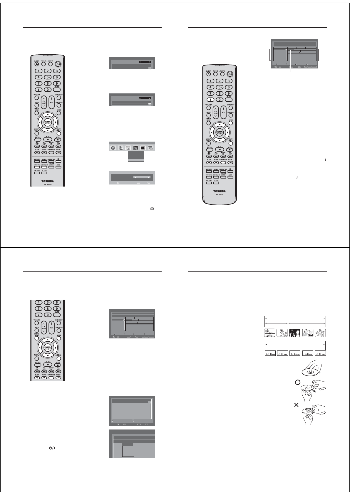
Multi audio/DVB-Subtitle/Using the Digital Service (UK only)
/
Multi audio
You can select your preferred Audio mode and DVB (digital TV)
subtitle Language.
The Multi audio menu will display the Audio mode and
Language options available with the current broadcast.
Press AUDIO SELECT to display the Multi audio menu.
1
The Audio mode and Language code will be displayed if
Note:
•
Dolby Digital audio can be selected
for some language options.
There is no sound output from the
main unit’s speakers when Dolby
Digital audio is selected.
You can only hear Dolby Digital audio
through the amplifier equipped with a
Dolby Digital decorder.
DVB-Subtitle can also be changed by
•
pressing of SUBTITLE repeatedly.
28
available.
To select Audio mode, press or . In general the below
2
audio modes will be supported in a service.
Stereo, Left, Right and L + R.
To select a Language code, press or to select code
within Language code list.
When completely different audio tracks are being broadcast
•
from the left and right channels, select Left or Right.
Press EXIT. Your selected audio preferences will be saved.
3
DVB-Subtitle
DVB-Subtitle is a feature supported in DVB (Digital Video
Broadcasting) applications in which the service shown can be
accompanied by a text display on the screen in parallel with the
corresponding audio service. The DVB-Subtitle feature can be
enabled or disabled at anytime.
Press or to select “Subtitle”, then press ENTER.
1
Press or to select your desired subtitle language from
2
the available languages.
To turn off the DVB-Subtitle, press or repeatedly until
3
‘Off’ appears in the Subtitle menu.
Press EXIT. Your selected subtitle language will be saved.
Using the Digital Service (UK only)
Some services bring you programmes with the Digital Service,
letting you experience DTV interactively.
When provided, the Digital Service will start when you press
Note:
When you display the DVB-Subtitle, Digital Service screen
•
cannot display. If you want display the Digital Service, setting
the DVB-Subtitle to Off.
Multi audio
Audio mode
No. Language Code
001 ENG
Multi audio
Audio mode
No. Language Code
001 ENG
Main menu System Configuration
CH1
CH2
ABC
ABC
CH3
Subtitle
egaugnaL
Navigate
Display Setup
Time Setup
Password Setup
Subtitle
Enter Exit
Texd
English
EPG (Electronic Program Guide)
The Guide menu shows the
available programme listings for the
next 8 days only, including today.
However, the guide menu will show
‘No Event Name’ for programmes
which are more than 8 days ahead,
or for programmes within the 8 days
when no programme information is
Stereo
L+R
i
i
CI
available.
.
Press GUIDE to display the Guide menu.
1
Service list :
Lists all the services that are currently available.
As you scroll through the service list by pressing or ,
the Event list will be refreshed accordingly, and you will see
the programme information for the currently highlighted
programme.
To scroll through the service list page by page, press Red
or Green button.
Events list :
List the events in a grid of rows and columns.
Each row shows the list of events that are available, for the
corresponding service in the service list. Within each row,
you can press or to navigate through the rest of the
events.
You can easily move to the Previous day or Next day in the
Events List by pressing Yellow or Blue button (the date
of the programme information you are currently viewing is
shown in the top right hand corner).
The full Event name along with the duration of the event will
be displayed in the bar above. Event title will be displayed
only if available otherwise ‘No Description’ message will be
displayed.
From within the Guide menu, you can open the Description
2
menu for the currently highlighted programme by pressing
The Guide/Description menu shows the extended event
description of an event. You can scroll and view the
complete event description of the event using or .
To return to the Guide menu, press
To clear the menu screen, press EXIT.
Guide 16:50 Sun 20/08/2008 TV
671_MNO_10Step_0820_0100_0120_Audio2_0100_0120...
MNO
PQS
STU
TCM
Service list
VWXYZ
SAT.1
ARTE
DEF
671_MNO_10step
671_M...
672_PQR_SMPTE_col...
Enter Exit Guide
View Info
02:0001:30
01:00Channels
671_M...
672_PQR_SMPTE_col...
673_STU_SDTV... 673_STU_SDTV Moving...
No Event Name
679_VWXYZ_Monosoo_0100_0300...
No Event Name
No Event Name
No Event Name
Page - Pag e + Prev.Day Next Day
Navigate
Highlighted programme
.
8002/80/02nuS671 MNO
Events
list
TV/Radio
.
29
EPG Timer
You can choose whether or not the screen switches on when the timer event begins - please see
page 18 (Rec screen status (LCD Power on/off)). This is so that if you are using the timer to make
a recording to your VCR or other device, the TV screen will not switch on unless you want it to.
If you try to switch to another channel while a timer event is in progress, the following message
will appear: ‘WARNING: CHANGING THE CHANNEL WILL INTERRUPT YOUR EVENT TIMER. ARE
YOU SURE YOU WANT TO PROCEED? YES/NO’. Select Yes or No according to your wishes.
Press GUIDE to display the Guide menu. Then press
1
/// to highlight the programme you want to set as a
Note:
•
When the EPG Timer starts, the
message “Event Timer Started” will
appear.
•
A maximum of eight Timers can be
programmed.
•
If the EPG Timer starts when it is
already switched on, it will start at the
exact time that is set. If it starts from
the standby mode, it will begin 20
seconds in advance of the stated time.
You cannot hasten the start time from
•
the original start time of the Event.
You cannot set with the same date
•
and time of another Event.
Press the Yellow
•
the start time of the event.
•
Press the Blue
time duration of the event.
•
If the EPG Timer begins during
standby mode, the
indicator on the unit will be lit in
orange. This is to indicate that an
EPG Timer event has begun in
standby mode.
•
When in power-off-condition, EPG
Timer cannot be activated.
button
button
30
to change
to change the
(Power)
timer event, then press ENTER.
Note:
•
If you select an event which has already started, the selected
program will be displayed on the screen, as you cannot set
the timer for a programme which has already started.
•
To display the stored timer events, press GUIDE twice.
The Event Timer menu (see step 3 below) will appear. You
can also delete or change the frequency (Once / Daily /
Weekly) of the stored timer events (but please note that
you cannot edit the time details that have been set from
the EPG).
The confirmation banner will be displayed.
2
Press or to select ‘Yes’ or ‘No’, then press ENTER (the
selected option is shown in blue).
The Event Timer menu will appear.
3
Press the Red button to set the Timer mode for a selected
event.
The Timer mode
4
specifies the
frequency of Timer
wake-up which can
be set as Once,
Daily or Weekly.
Press ENTER to
save the selected
Timer mode.
Note:
To delete a timer event, select the specified event, then
press the Green
To return to the Guide menu, press DIGITAL MENU.
5
To clear the menu screen, press EXIT.
Guide 16:50 Sun 20/08/2008 TV
671_MNO_10Step_0820_0100_0120_Audio2_0100_0120...
01:00Channels
671_M...
MNO
672_PQR_SMPTE_col...
PQS
673_STU_SDTV... 673_STU_SDTV Moving...
STU
TCM
No Event Name
VWXYZ
679_VWXYZ_Monosoo_0100_0300...
SAT.1
No Event Name
No Event Name
ARTE
No Event Name
DEF
Page - Page + Prev.Day Next Day
Navigate
Event Timer
Service Name Mode Date Time Duration
BBC ONE Once 26/02/08 08:10 00:23
Timer mode
Edit Timer Edit Duration
Navigate
Event Timer
Service Name Mode Date
BBC ONE Once 26/02
Once
Daily
Weekly
button
.
671_M...
Enter Exit Guide
View Info
Delete Timer
02:0001:30
671_MNO_10step
672_PQR_SMPTE_col...
Enter Exit
Disc
DVD discs must be Region 2 or Region ALL type to play on this unit.
The suitable disc formats are: DVD-Video, DVD-R/-RW (Video format only), Audio CD, CD-R/CD-RW and
Video CD.
Some CD-R/RW discs may be incompatible.
•
This unit can play an 8cm disc. Please do not use a disc adapter. It may cause trouble.
•
Please do not insert any disc of an irregular shape into the unit, as it may interfere with the function of the unit.
You may not be able to remove it.
•
Please do not use after market accessories, such as a ring protector, as this may cause trouble with the
operation of the unit.
Do not play DVD-ROM, DVD-Audio, CD-G, Photo CD or SVCD to prevent accidental erasure of prerecorded
8002/80/02 nuS 671 MNO
TV/Radio
material.
Title
When two or more movies are recorded on a disc, the
disc is divided into two or more sections. Each section
is called a “TITLE”.
Chapter
The titles can be subdivided into many sections.
Each section is called a “CHAPTER”.
Track
Video CD/Audio CD can contain several items.
These are assigned to tracks.
Removing Disc from Case
Be sure to hold the edge of disc. Do not touch the
surface of the disc.
Pick up the disc gently from the case.
•
Do not scratch the disc.
•
Do not get dirt on the surface of the disc.
•
Do not stick a label or adhesive tape on the disc.
•
Do not drop or bend the disc.
Storing Disc
•
Store the disc in the case to avoid risk of scratches, dirt or damage.
•
Do not leave disc exposed to direct sunlight or in hot or humid places.
Cleaning Disc
Wipe the disc with a clean, dry cloth from center to edge.
•
Do not wipe in circular direction.
•
Do not use liquid or aerosol cleaners.
On Video CDs
This unit supports Video CDs equipped with the PBC (Version 2.0) function.
(PBC is the abbreviation of Playback Control.) You can enjoy two playback
variations depending on types of discs.
•
Video CD not equipped with PBC function
(Version 1.1) Sound and movie can be played on this TV/DVD in the same way as an audio CD.
•
Video CD equipped with PBC function
(Version 2.0) In addition to operation of a Video CD not equipped with the PBC function, you can enjoy
playback of interactive software with search function by using the menu displayed on the TV screen
(Menu Playback). Some of the functions described in this owner’s manual may not work with some discs.
To turn off the PBC
1.
Press PLAY MODE in the Stop mode.
Press / to select “Mode”, then press ENTER repeatedly until “Off” appears.
2.
3.
Press PLAY MODE again to clear the screen.
To turn on the PBC
Follow the above step 1~2, then press ENTER repeatedly until “PBC” appear.
CHAPTER 1
TRACK 1 TRACK 2 TRACK 3 TRACK 4 TRACK 5
DVD DISC
TITLE1 TITLE2
CHAPTER 2 CHAPTER 2 CHAPTER 3CHAPTER 1
Video-CD/Audio-CD
31
Page 13
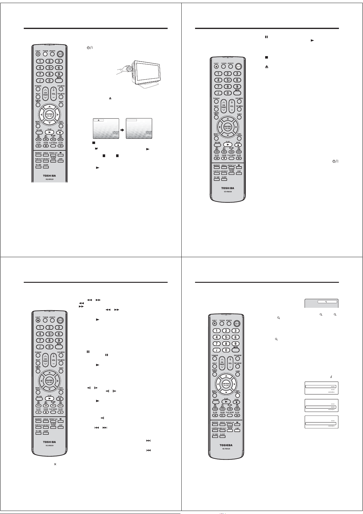
Playing a disc
Note:
•
If the unit does not operate
properly:
Static electricity, etc., may affect the
player’s operation.
Disconnect the AC power cord once,
then connect it again.
If a disc is inserted during some modes
•
other than DVD mode, it may switch to
DVD mode and then playback may be
begun automatically.
About inserting disc:
•
If the unit is slanted or moved while
inserting disc, the disc may get
damage.
32
This section shows you the basics on how to play a disc.
Basic playback (DVD/VCD/Audio CD)
Preparation
on the unit.
Press
Press TV/DVD on the remote control to select the DVD
1
mode.
Place the disc in the
2
disc slot with the label
side facing forward.
(If the disc has a label.)
Do not place a disc which is unplayable in this unit.•
On the TV-screen, “ ” changes to “Reading” and then
3
playback commences.
A menu screen will appear on the TV screen if the disc
•
has a menu feature.
Press /// to select title, then press ENTER.
•
Title is selected and play commences.
Press to end playback.
4
The unit records the stopped point, depending on the
•
disc. “
” appears on the screen. Press
resume playback (from the scene point).
If you press again (“ ” appears on the screen.), the
•
unit will clear the stopped point.
To start playback in the stop mode
Press PLAY (
).
Reading
PLAY
( ) to
Playing a disc
To pause playback (still mode)
Press
during playback.
To resume normal playback, press PLAY (
The sound is muted during still mode.
•
To stop playback
Press .
To remove the disc
Press
.
Remove the disc after the disc comes out.
Note:
If a non-compatible disc is loaded, “Incorrect Disc”, “Region
•
Code Error” or “Parental Error” will appear on the TV screen
according to the type of loaded disc. In this case, check your
disc again (see pages 31 and 50).
Some discs may take a minute or so to start playback.
•
When you set a single-faced disc label backwards (i.e.
•
the wrong way), “Reading” will appear on the display for a
few minutes and then “Incorrect Disc” will continue to be
displayed.
Some discs may not work the resuming facility.
•
Resuming cannot function when you play a PBC-featured
•
Video CD while the PBC is on. To turn off the PBC, see page
31.
Some playback operations of DVDs may be intentionally fixed
•
by software producers. Since this unit plays DVDs according
to the disc contents the software producers designed, some
playback features may not be available. Also refer to the
instructions supplied with the DVDs.
Do not move the unit during playback. Doing so may damage
•
the disc.
In many instances, a menu screen will appear after playback
•
of a movie is completed. Prolonged display of an on-screen
menu may damage your television set, permanently etching
that image onto its screen. To avoid this, be sure to press
on your remote control once the movie is completed.
•
There may be a slight delay between the button is pressed
and the function activates.
).
33
Playing a disc
Note:
•
A prohibition symbol “
at the upper right of the screen. This
symbol means either the feature you
tried is not available on the disc, or
the unit cannot access the feature
at this time. This does not indicate a
problem with the unit.
34
” may appear
You can play discs at various speeds.
Playing in fast reverse or fast forward directions (DVD/
VCD/Audio CD)
Press
or during playback.
: Fast reverse playback
: Fast forward playback
Each time you press
To resume normal playback
Press PLAY (
Note:
•
The unit mutes sound during reverse and forward scan of
DVD/VCD discs.
•
The playback speed may differ depending on the disc.
You can use fast reverse/fast forward playback for mp3/DivX
•
CD.
Playing frame by frame (DVD/VCD)
Press
during still playback.
Each time you press
To resume normal playback
Press PLAY (
Note:
•
You can use frame by frame playback for DivX
The sound is muted during frame by frame playback.
•
Playing in slow-motion (DVD/VCD)
Press
or during playback.
Each time you press
To resume normal playback
Press PLAY (
Note:
•
The sound is muted during slow-motion playback.
•
You can use slow motion playback for DivX
•
Reverse slow (
Locating a chapter or track (DVD/VCD/Audio CD)
Press SKIP
number you want.
Playback starts from the selected chapter or track.
To locate succeeding chapters or tracks, press SKIP
Playback starts from the beginning of the succeeding chapter or
track.
To locate the preceding chapter or track, press SKIP
in quick succession. Playback starts from the beginning of the
preceding chapter or track.
or , the playback speed changes.
).
, the picture advances one frame.
).
®
CD.
or , the slow-motion speed changes.
).
®
) does not work on VCD and DivX® CD.
or repeatedly to display the chapter or track
CD.
.
twice
Zooming/Locating desired scene
Zooming (DVD/VCD)
This unit will allow you to zoom in the frame image. You can then
make selections by switching the position of the frame.
Press ZOOM during playback.
1
The centre part of the image will be zoomed in.
Each press of ZOOM will change the ZOOM
(x 1.5) and 3 (x 2.0).
Press /// to view a different part of the frame.
2
You may move the frame from the centre position to UP,
DOWN, LEFT or RIGHT direction.
In the zoom mode, press ZOOM repeatedly to return to a
®
3
Locating desired scene (DVD/VCD/Audio CD)
Use the title, chapter and time recorded on the DVD disc to
locate the desired point to playback. In the case of VCD/Audio
CD discs, time and track are used to locate the desired point to
playback. To check the title, chapter/track and time, press .
1
2
3
4
Off).
1:1 view (
Note:
•
You can select the Pause or Slow in the zoom mode.
•
Some discs may not respond to zoom feature.
•
Zoom function can be used for DivX
Press JUMP during playback
or resume stop mode.
Press or to select the
“Title/Track”, “Chapter” or
“Time”.
Press Number buttons (0–9)
to input the number.
If you input a wrong number,
•
press CANCEL.
Refer to the package
•
supplied with the disc to
check the numbers.
Press ENTER. Playback starts.
•
When you change the title, playback starts from Chapter
1 of the selected title.
•
Some discs may not work in the above operation.
Note:
•
In case of the Audio CD and Video-CD, only Track and
Time can be selected.
•
In case of the Video-CD playback with PBC, the JUMP
does not work. Turn off the PBC (see page 31).
•
Only Time search function can be used for DivX
Title
Chapter
Time
Title
Chapter
Time
Title
Chapter 12
Time
®
CD.
1(x 1.3), 2
Jump
Jump
Jump
®
1
CD.
35
Page 14
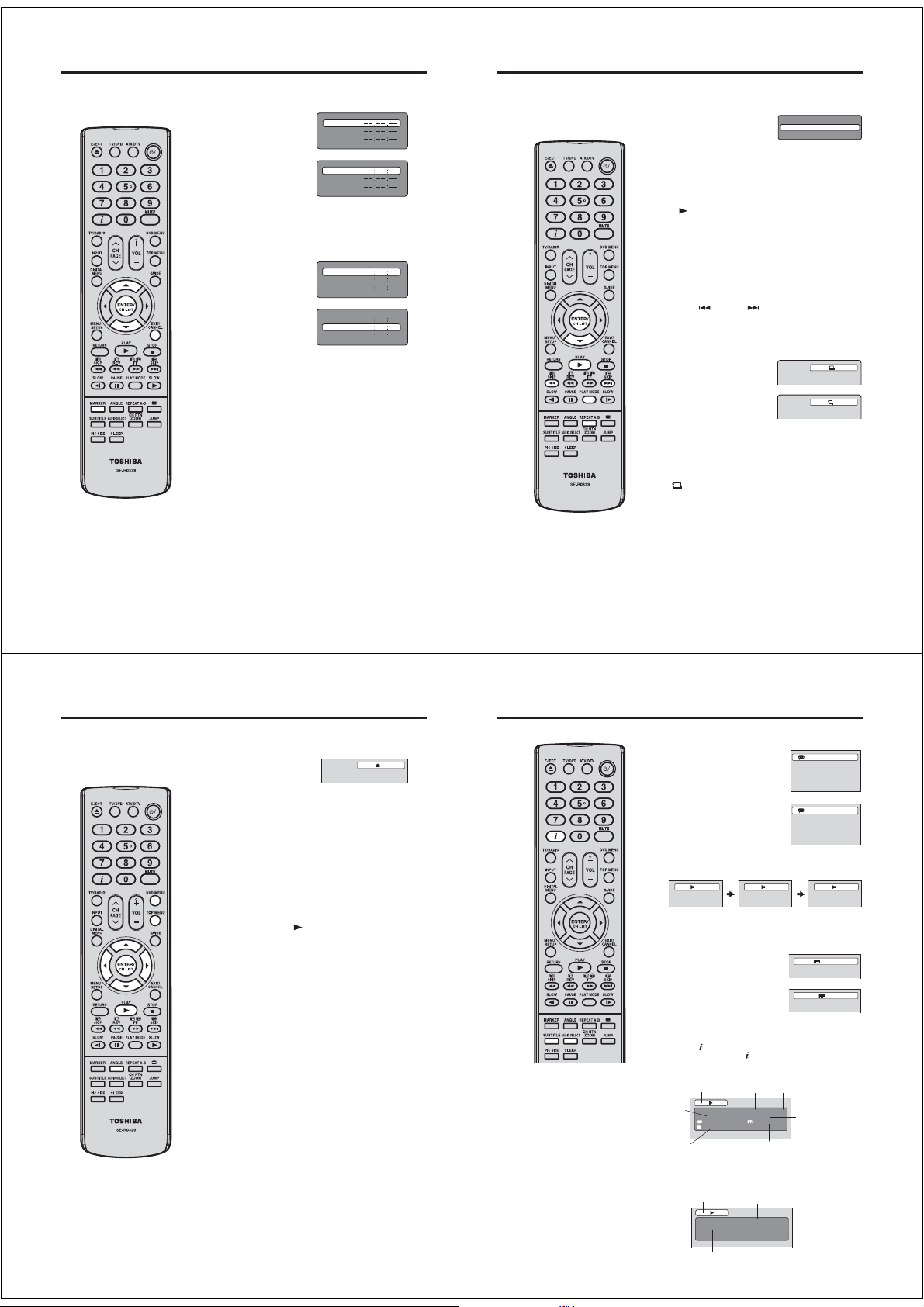
Marking desired scenes
Note:
Some discs may not work with the
•
marking operation.
The marking is cancelled when you
•
eject the disc or turn the power off.
Some subtitles recorded around the
•
marker may fail to appear.
In case of Video CD with PBC,
•
Marker function is prohibited.
Marker function does not work with
•
MP3/JPEG CD/DivX
36
®
CD.
Marking the scenes (DVD/VCD/Audio CD)
The unit stores the points that you want to watch again up to 3
points. You can resume playback from each scene.
Press MARKER during
1
playback.
Select the blank Marker using
2
or .
Then press ENTER at the
desired scene.
Repeat this procedure to set the other 2 scenes.•
Press MARKER to clear this display.
3
Marker 1
Marker 2
Marker 3
Marker 1
Marker 2
Marker 3
2700 54
Returning to the scenes (DVD/VCD/Audio CD)
Press MARKER during
1
playback or stop mode.
Press or to select the
2
Marker 1-3.
Press ENTER.
3
Playback starts from the marked scene.
To cancel the Marker
Follow the above steps 1~2, then press CANCEL.
Marker 1
Marker 2
Marker 3
Marker 1
Marker 2
Marker 3
2700 54
01
160825
02
27
00
01
16
02
08
Repeat playback/A-B Repeat playback
Repeat playback (DVD/VCD)
Press PLAY MODE during playback or stop mode.
1
Press ENTER repeatedly to
2
select “Chapter” or “Title”.
The unit automatically starts repeat playback after finishing
the current title or chapter.
[Video CD]
Press to select “Repeat”.
Press ENTER to select “Track” or “All”.
If you set the repeat mode during stop mode, press PLAY
•
(
) to start Repeat playback.
Press PLAY MODE again to clear the screen.
3
To resume normal playback
Select Repeat : “Off” in step 2.
Note:
Some discs may not work with the repeat operation.
•
In case of Video CD with PBC, Repeat functions are
31
54
25
31
•
prohibited during playback.
Chapter repeat function is cancelled whenever
•
SKIP (
) or SKIP ( ) is pressed.
A-B Repeat playback (DVD/VCD/Audio CD)
A-B repeat playback allows you to repeat selection between two
selected points.
Press REPEAT A-B during
1
playback.
The start point is selected.
Press REPEAT A-B again.
2
The end point is selected.
Playback starts at the point that
you selected. Playback stops
at the end point and returns
to Point A automatically, then
starts again.
To resume normal playback
Press REPEAT A-B again.
Off
“
” appears on the screen.
Note:
•
In A-B Repeat mode, subtitles near the A or B locations
may not be displayed.
•
You may not be able to set A-B Repeat for the scenes
that include multiple angles.
•
A-B Repeat playback does not work when Repeat
playback is activated.
•
You may not be able to set A-B Repeat during certain
scenes of the DVD.
•
A-B Repeat does not work with an interactive DVD and
MP3/JPEG CD.
•
In case of Video CD with PBC, A-B Repeat is prohibited.
Play Mode
Repeat : Off
A
AB
37
Changing angles/Title selection/DVD menu
Changing angles (DVD)
When playing back a disc recorded with multi-angle facility, you
can change the angle that you are viewing the scene from.
Press ANGLE during
1
playback.
The current angle will appear.
Press ANGLE repeatedly until the desired angle is
2
selected.
Note:
Depending on the DVD, you may not be able to change
•
the angles even if multi-angles are recorded on the DVD.
Title selection (DVD)
Two or more titles are recorded on some discs. If the title menu
is recorded on the disc, you can select the desired title.
Press TOP MENU during playback.
1
Title menu appears on the screen.
Press /// to select the desired title.
2
Press ENTER or PLAY ( ).
3
The playback of the selected title will start.
Note:
Depending on the DVD, you may not be able to select
the title. Depending on the DVD, a “title menu” may
simply be called a “menu” or “title” in the instructions
supplied with the disc.
DVD menu (DVD)
Some DVDs allow you to select the disc contents using the
menu.
When you playback these DVDs, you can select the subtitle
language, soundtrack language, etc, using the menu.
Press DVD MENU during playback.
1
The DVD menu appears on the screen.
Press DVD MENU again to resume playback at the scene
•
when you pressed DVD MENU.
Press /// to select the desired item.
2
Press ENTER.
3
The menu continues to another screen. Repeat steps 2 and
3 to set the item completely.
Note:
Depending on the DVD, you may not be able to resume
•
playback from the scene point when you press DVD
MENU.
38
Changing soundtrack language/Subtitles/Disc status
Changing Soundtrack Language (DVD/VCD)
You can select the language when you play a multilingual disc.
Press AUDIO SELECT during
1
1/2
Note:
•
If the desired language is not heard
after pressing the button several
times, the language is not recorded
on the disc.
•
The selected soundtrack language
is cancelled when you eject the
disc. The initial default language or
available language will be heard if the
disc is played back again.
•
Depending on the DVD, you may not
be able to change subtitles, or to turn
subtitles on or off.
•
While playing a DVD, the subtitle may
change when you loaded or eject the
disc.
•
In some cases, a selected subtitle
language may not be changed
immediately.
playback.
The current soundtrack language
will appear.
Press AUDIO SELECT repeatedly
2
until the desired language is
selected.
The on screen display will
•
disappear after a few seconds.
In case of Video CD playback
Audio type changes as follows each
time you press AUDIO SELECT.
LR L R
Subtitles (DVD)
When playing back a disc recorded with subtitles, you can
select the subtitle language or turn the subtitle off.
Press SUBTITLE repeatedly during
1
playback until the desired language
is selected.
To turn off the subtitle, press
2
SUBTITLE until “Off” appears.
The on screen display will
•
disappear after a few seconds.
Disc status (DVD/VCD)
With press of , the status of the disc will appear on the screen.
To cancel the display, press
[DVD]
DISC
OPERATION
TITLE NO.
DVD 00:15:25 01:41:39
Title 1/3 Chapter 2/24
1/1 Eng Dolby Digital 1/2 Eng
1/1
ANGLE NO.
AUDIO LANGUAGE A KIND OF AUDIO
[Video CD]
DISC
OPERATION
VCD 00:08:32 00:51:03
Track 3/15
TRACK NO.
again.
ELAPSED
TIME
SUBTITLE LANGUAGE
ELAPSED
TIME
TOTAL
TIME
TOTAL
TIME
1/2 Eng Dolby Digital
2/2 Fre Dolby Digital
1/5 Eng
Off
CHAPTER NO.
39
Page 15
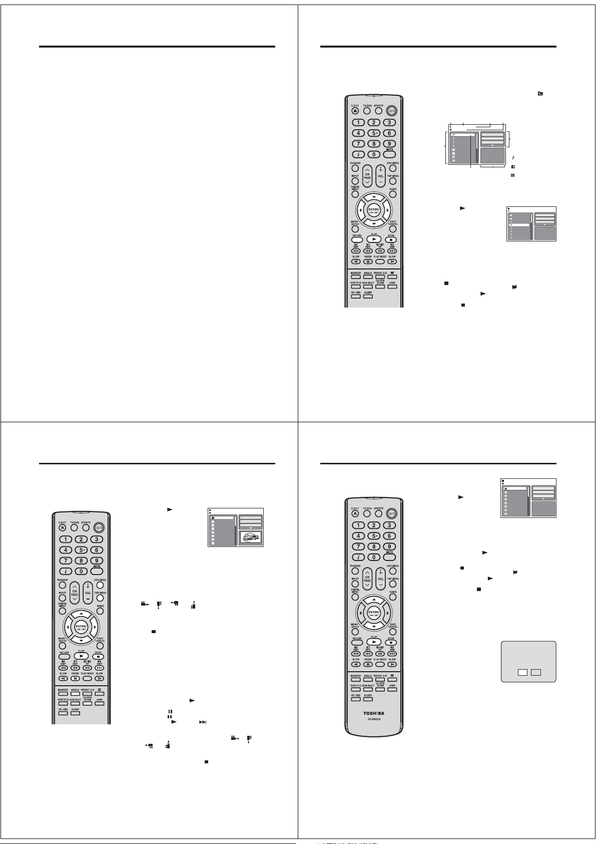
MP3/JPEG/DivX® and Audio CD operation
This unit can playback the MP3/JPEG/DivX®-data which has been recorded on CD-R/RW. Audio CD also
can be played back. To produce the MP3/JPEG/DivX
and a MP3/JPEG/DivX
This unit requires discs/recordings to meet certain technical standards in order to achieve optimal playback
quality.
There are many different types of recordable disc formats (including CD-R containing MP3 files). Not all
recordable discs will produce optimal playback quality. The technical criteria set forth in this instruction
manual are meant only as a guide. Use of CD-RW for MP3 files is not recommended.
MP3/JPEG/DivX® - data information
Limitations on MP3/JPEG/DivX® playback
MP3/JPEG/DivX
•
“.mp3”, “.jpg”, “div”, “divx”, “avi”.
•
MP3/JPEG/DivX
•
This unit can read 2000 files per disc. If one disc has more than 2000 files, it reads up to 2000 files, the
remaining files will be omitted.
MP3/JPEG/DivX
•
•
It may take more than one minute for this unit to read MP3/JPEG/DivX
Music recorded by “Joliet Recording Specification” can be played back.
•
•
The music files recorded by “Hierarchical File System” (HFS) cannot be played.
Limitations on displaying of the file name.
The maximum number for display is 15 characters. Long file names will be condensed.
•
•
Available characters for display are the following:
capital or small alphabets of A through Z, numbers of 0 through 9, and _ (under score).
•
Other characters than those above are replaced in hyphen.
To playback MP3/JPEG/DivX
1.
Use MP3/JPEG/DivX
2.
Insert two or three digit number in the head of file name. (ex. “01” “02” or “001” “002”).
3.
Refrain from making too many sub-folders.
CAUTION:
•
Some MP3/JPEG/DivX
•
The CD-R/RW that has no music data or non MP3/JPEG/DivX
Standard sampling frequency and the bit rate:
MP3
MPEG-1 Audio
32kHz, 44.1kHz, 48kHz
32kbps ~ 320kbps (constant bit rate or variable bit rate)
The recommend recording setting for a high-quality sound is 44.1kHz of sampling frequency and
128kbps of constant bit rate.
®
DivX
video
®
DivX
version: DivX® 3, 4, 5, and 6 (specifically 3.1.1, 4.1.2, 5.0.2, 5.0.5, 5.1.1, 5.2.1, 6.0 at Home
Theater profile).
Audio format: MPEG1 Layer2 (MP2), MPEG1 Layer3 (MP3)
Sampling frequencies: 32kHz, 44.1kHz, 48kHz
Bit rate: 32kbps ~ 320kbps
Resolution: Max 720 x 576 (at 25fps), Max 720 x 480 (at 30fps)
®
-encoding Software (not supplied). The Apple-HFS-System cannot be played.
®
CD are standardized by ISO9660, its file name must include following extensions;
®
CD must be corresponded to the ISO standardized files.
®
CDs cannot be used for the purpose of recording on this unit.
®
CD in the recorded order.
®
software that records data alphabetically or numerically.
®
CDs cannot be played back depending on the recording conditions.
®
-data, you need a Windows-PC with CD-RW drive
®
files depending on its structure.
®
files cannot be played back.
MP3/JPEG/DivX® and Audio CD operation
Note:
During MP3/JPEG-Playback, you
•
cannot use JUMP and A-B Repeat
functions.
You can use Repeat (Track or All),
•
Random functions and Program
playback for MP3/JPEG/DivX
Playback (See pages 44, 45)
Loading CD
Load a MP3/JPEG/DivX® CD or an Audio CD into the disc slot.
1
A file browser screen will appear on the screen.
2
•
In case the current directory includes 9 files or more,
press or to scroll in the file list.
•
To see contents in folder, select the folder and then press
ENTER. To return to the parent directory, select “
Up ...” then press ENTER.
•
In case of a CD containing a mixture of MP3, JPEG and
®
DivX
files, the files are played back by selecting them
from the file browser.
Operation status
File list
/MP3-5.MP3
MP3-5
MP3-6
MP3-7
MP3-8
Picture-1
Picture-2
Movie-1
Movie-2
File number
1/15 00:00:00
Elapsed time
Select Files
Repeat :Off
Mode :Off
Music Playing
Preview windowCursor
Selected file name
MP3 and Audio CD playback
In the file browser, press / to select the desired file.
1
When PLAY (
displaying file browser displayed,
playback begins automatically
starting from the first file. In this
case, if the first file is an MP3 file,
only MP3 files are played back in
order.
If the first file is a JPEG file, the first JPEG file is played
back. If the first file is a DivX
played back. If there is no file at a root directory, playback
does not begin automatically.
Press ENTER.
2
The selected file starts playing back.
Press to end playback.
3
•
•
Select Files
The file type to make it display in the file browser can be chosen.
1.
Press or to select “Select Files” at right column in the file
browser.(“Select Files” is not applicable to Audio CD.)
2.
Press ENTER, then press or to select file type from the
list (Music, Picture or Movie).
3.
®
Press ENTER to add/remove check mark. Checked file type
will be displayed in the file browser.
4.
Press RETURN to save the setting.
) is pressed after
®
file, the first DivX® file is
The unit records the stopped point. “
screen. Press PLAY (
scene point).
If you press
the stopped point.
) to resume playback (from the
again or unload the disc, the unit will clear
Tool kit
window
File type
: Indicates Music file
(Audio CD/MP3)
: Indicates Picture file
(JPEG)
: Indicates Movie file
®
video)
(DivX
/MP3-2.MP3
Folder-1
Folder-2
MP3-1
MP3-2
MP3-3
MP3-4
MP3-5
MP3-6
” appears on the
Select Files
Repeat :Off
Mode :Off
JPEG Preview
Go
40
MP3/JPEG/Divx® and Audio CD operation
JPEG playback
In the file browser, press / to select the desired JPEG
1
file.
To display a thumbnail list, press DVD MENU.
Press /// to select the desired file.
Note:
•
During JPEG playback, you cannot
use Jump and A-B Repeat functions.
•
When an image exceeds 5760
x 3840 pixels, the entire image
(preview window or thumbnail list)
may not be displayed on a screen.
•
It may have a longer interval due to
the size of data.
42
(To return to the file browser, press TOP MENU.)
When PLAY (
after displaying the file
browser, playback begins
automatically starting from
the first file. In this case, if the
first file is a JPEG file, the first
JPEG file is played back.
If the first file is an MP3 file, only MP3 files are played back
in order. If the first file is a DivX
played back. If there is no file at a root directory, playback
does not begin automatically.
Press ENTER. The selected picture appears on the screen.
2
Rotating an image
You can rotate an image by 90 degrees.
Press ANGLE during playback of the image.
“
Zooming an image
Zoom function also can be used in viewing JPEG files.
Press ZOOM (See “Zooming” on page 35).
Press to end playback.
3
The file browser appears on the screen. If you want to watch
the other file, repeat steps 1 ~ 2.
Slide show playback
The slide show enables you to view pictures (files) one after
another automatically.
Preparation
Set “JPEG Interval” setting to “Off”, “5 Seconds”, “10 Seconds”
or “15 Seconds” (See page 49).
Select your desired starting file for the slide show in step 1
1
above.
Press ENTER or PLAY ( ) to start slide show from the
2
selected file.
•
•
•
•
) is pressed
”, “ ”, “ ” or “ ” appears on the screen.
If you press
during the slide show, the slide show stops
” appears briefly on the screen.
temporary. “
Press PLAY (
show.
If the picture appears upside down or sideways, press
ANGLE repeatedly until it’s right side up. “ ”, “ ”,
“
When the slide show playback finished, the file list
appears.
To stop the slide show, press . The file list appears.
) or SKIP ( ) again to resume the slide
” or “ ” appears on the screen.
/Picture-01.JPG
Picture-01
Repeat :Off
Picture-02
Picture-03
Mode :Off
Picture-04
Picture-05
Picture-06
Picture-07
Picture-08
®
file, the first DivX® file is
Select Files
JPEG Preview
W: 2048 H: 1536
MP3/JPEG/Divx® and Audio CD operation
Note:
•
In order to play DivX
on this unit, you first need to register
the unit with registration code. See
page 50.
•
Depending on the recording
conditions of DivX
be able to use fast reverse/forward
playback or JUMP function.See
pages 34, 35.
®
VOD content
®
file, you may not
DivX® playback
In the file browser, press
1
/ to select the desired
file.
When PLAY ( ) has been
pressed after the file browser
displayed, playback begins
automatically starting from the
first file. In this case, if the first
file is a JPEG file, the first JPEG file is played back. If the first
®
file, the first DivX® file is played back. If the first
file is a DivX
file is an MP3 file, only MP3 file are played back in order. If
there is no file at a root directory, playback does not begin
automatically.
Press ENTER or PLAY ( ). The selected DivX® movie will
2
be played back on the TV screen.
Press STOP ( ) to end playback.
3
•
The unit records the stopped point. “
TV screen. Press PLAY (
the scene point).
•
If you press STOP (
will clear the stopped point. To watch the other file, repeat
steps 1 ~ 2.
Playing DivX® VOD content
DivX® VOD content is protected by DRM (Digital Rights Management) system. This restricts playback of content to specific
registered devices.
If the incorrect DRM file is loaded,
“Authorization Error This player is
not authorized to play this video.”
will appear on the screen.
When you attempt to play DivX
VOD, the number of plays is limited
and the right message will appear
on the screen. If you wish to play it,
select “Yes”.
If the number of plays goes over
•
the limit, then “Rental Expired”
will be displayed. In this case,
the file will not be played.
/Movie-01.DIVX
Movie-01
Movie-02
Movie-03
Movie-04
Movie-05
Movie-06
Movie-07
Movie-08
) to resume playback (from
Select Files
Repeat :Off
Mode :Off
JPEG Preview
” appears on the
) again or unload the disc, the unit
View DivX(R) VOD Rental
This rental has 5 views left.
Do you want to use one
®
of your 5 views now?
NoYe s
41
43
Page 16
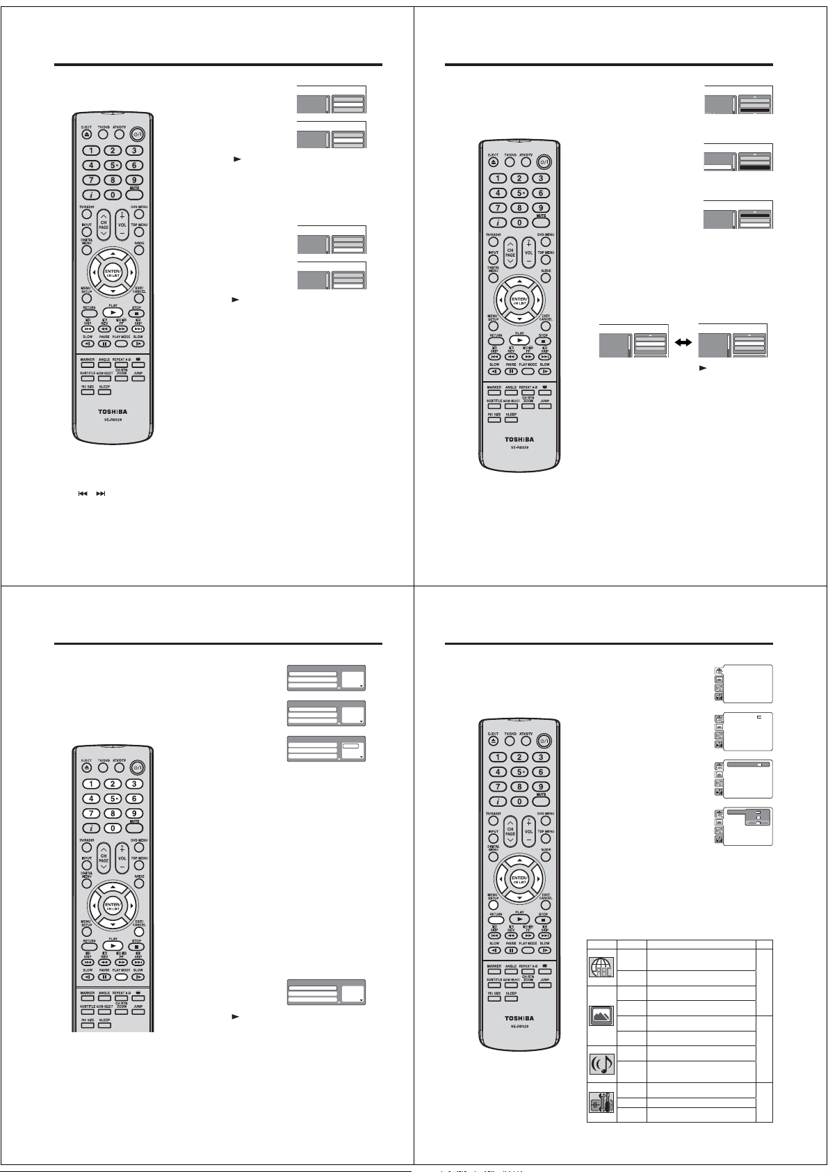
MP3/JPEG/DivX® and Audio CD operation
Repeat playback (Audio CD/MP3/JPEG/DivX®)
In the file browser, press ///
1
to select “Repeat” during stop
mode.
Press ENTER repeatedly to select
2
“Track” or “All”.
Press PLAY ( ).
3
The unit automatically starts repeat playback after finishing
the current track.
To resume normal playback
Select Repeat : “Off” in step 2.
Random playback (Audio CD/MP3/JPEG/DivX®)
In the file browser, press ///
1
to select “Mode” during stop mode.
Press ENTER to select “Random”.
2
Press PLAY ( ).
3
The Random playback will start.
To resume normal playback Select Mode : “Off” in step 2.
Note:
The repeat or random function is
•
cancelled when you eject the disc or
turn the power off.
The track repeat function is cancelled
•
or is pressed.
when
In case of Audio CD, the function of
•
A-B Repeat also can be used. See
“A-B Repeat playback” (See page
37).
44
Folder-1
Folder-2
MP3-1
Folder-1
Folder-2
MP3-1
Folder-1
Folder-2
MP3-1
Folder-1
Folder-2
MP3-1
Select Files
Repeat :Off
Mode :Off
Select Files
Repeat :Track
Mode :Off
Select Files
Repeat :Off
Mode :Off
Select Files
Repeat :Off
Mode :Random
MP3/JPEG/DivX® and Audio CD operation
Program playback (Audio CD/MP3/JPEG/DivX®)
In the file browser, press///
1
to select “Edit Mode”, then press
ENTER.
When “Edit Mode” is black color,
you can mark the files which you
want to add into Program list.
Press /// to select the file
2
you want to add into the program
list.
Press ENTER. Selected file was
marked. Repeat this procedure to
select the other files.
Press /// to select “Add To
3
Program”. Then press ENTER.
All marked files are added into
the program list. (The maximum
number of files can be added is
30.)
When you finish storing the files
you want into the Program list,
select “Edit Mode” again and press
ENTER to release edit mode.
Press / to select “Program View”, then press ENTER.
4
Program View shows only the programed files that you have
added in Step 2.
Browser View Program View
Folder-1
Folder-2
MP3-1
MP3-2
In the Program View, press PLAY ( ). The files start to
5
playback in programmed order that were added by you.
To remove file from program list in stop mode
In the Edit Mode, switch to Program View. Select the files you
want to remove, then press ENTER. Select “Clear Program” and
press ENTER. Marked file is removed from program list.
Note:
The program function is cancelled when you eject the disc or
•
turn the power off.
Edit Mode
ProgramView
AddTo Program
Folder-1
Repeat :Off
Folder-2
Mode :Off
MP3-1
P3-1.MP3
Folder-1
Folder-2
MP3-1
Folder-1
Folder-2
MP3-1
MP3-1
MP3-2
MP3-5
MP3-3
Repeat :Off
Mode :Off
ProgramView
AddTo Program
Edit Mode
Browser View
Clear Program
Edit Mode
Edit Mode
Edit Mode
45
Program playback/Random playback
You can arrange the playback order
of tracks or files on the disc. And
the unit can also select tracks or
files at random and playback them.
These feature works for Video CD.
For Audio CD and MP3/JPEG/DivX
CD, please see “Random playback
(Audio CD/MP3/JPEG/DivX
page 44 and “Program playback
(Audio CD/MP3/JPEG/DivX
page 45.
Note:
•
In case of Video CD with PBC, you
cannot set Program playback.
•
The program is cancelled when you
eject the disc or turn the power off.
•
In case of Video CD with PBC, you
cannot set Random function during
playback.
46
®
®
)” on
)” on
®
Program playback (VCD)
Press PLAY MODE during
1
stop mode.
Press / to select “Mode”,
2
then press ENTER to select
“Program”.
Press / to select the
3
programming position.
Use Number buttons (0–9)
to input the track numbers on
sequentially.
If you input a wrong number, press CANCEL.•
Press / to return to the left column, then press / to
4
select the “Program Playback” and press ENTER.
The programs you selected will start to playback in order.
•
To resume normal playback, select Mode “Off” in step 2.
To change the program
1.
Select Mode to “Program” (as step 2), press /// to
select the track number you want to change, then press
CANCEL.
2.
Press Number buttons (0–9) to overwrite the new track
number.
To clear the program one by one
Select Mode to “Program”, press /// to select the
track number. Then press CANCEL.
To clear all the programs
In the above column, press / to select “Clear Program”.
Then press ENTER.
Random playback (VCD)
Press PLAY MODE during playback or stop mode.
1
Press / to select “Mode”,
2
then press ENTER to select
“Random”.
Press PLAY ( ).
3
The Random Playback will start.
If you set “Random” during playback mode, Random
•
playback will begin after the track that is currently being
played has ended.
To resume normal playback, select Mode “Off” in step 2.
•
Play Mode
Mode : Off
Repeat : Off
Program Playback
Play Mode
Mode : Program
Repeat : Off
Program Playback
Play Mode
Mode : Program
Repeat : Off
Program Playback
Play Mode
Mode : Random
Repeat : Off
Program Playback
1 – – –
2 – – –
3 – – –
1 – – –
2 – – –
3 – – –
1 9
2 – – –
3 – – –
1 – – –
2 – – –
3 – – –
Customizing The Function Settings
You can change the default settings
to customize performance to your
preference.
Setting procedure
Press SETUP in stop mode.
1
The following on-screen display
appears.
Press or to select the desired
2
section, then press or ENTER.
First option will be highlighted.
3
Press or to select the desired
option.
Then press or ENTER.
4
The selectable settings will appear.
Change the selection using or , by referring to the
5
corresponding pages 48 ~ 50.
Press ENTER to save the setting.
Repeat steps 3 and 5 to change other option.
•
To select another section, go back to step 2 by pressing
•
or RETURN repeatedly.
To clear SETUP screen, press SETUP or press RETURN
6
repeatedly.
Setting details
Section Option Details
Menu
To select the language of “Menu”,
Subtitle
“Subtitle” and “Audio” if more than one
Audio
languages are available on the disc.
OSD To select a preferred language for on
screen display.
TV
To select a picture size according to the
Screen
aspect ratio of your TV.
Display To turn On or Off the operational status
display on the screen.
Picture
To select a preferred picture mode from
Mode
“Video”, “Film” or “Auto”.
JPEG
To select a preferred setting for the slide
Interval
show playback.
Night
To select On or Off for Night Mode.
Mode
Digital
To select a digital output sound
Out
format corresponding to your system
connection.
Parental To select a preferred parental level for
the parental setting.
Password To change the password.
DivX(R)
To display your 8-character registration
VOD
code.
Parental : Off
DRC : Off
E.B.L. : Off
Menu : English
Set Password
QSound : On
TV Screen : 4:3
Subtitle : English
Output : Interlace
Display : On
Audio : English
DivX(R) VOD
Picture Mode : Auto
OSD : English
JPEG Interval : 5 Seconds
Screen Saver : On
Parental : Off
DRC : Off
Menu : English
TV Screen : 16:9
Set Password
QSound : On
Subtitle : English
Display : On
Output : Interlace
Audio : English
Picture Mode : Auto
DivX(R) VOD
JPEG Interval : Off
Parental : Off
DRC : Off
Menu : English
TV Screen : 16:9
Set Password
QSound : On
Subtitle : English
Display : On
Output : Interlace
Audio : English
Picture Mode : Auto
DivX(R) VOD
JPEG Interval : Off
TV Screen 4:3
TV Screen 4:3
Display : On
Picture Mode : Aut
JPEG Interval : Off
4:3
16:9
Page
48
49
50
47
Page 17
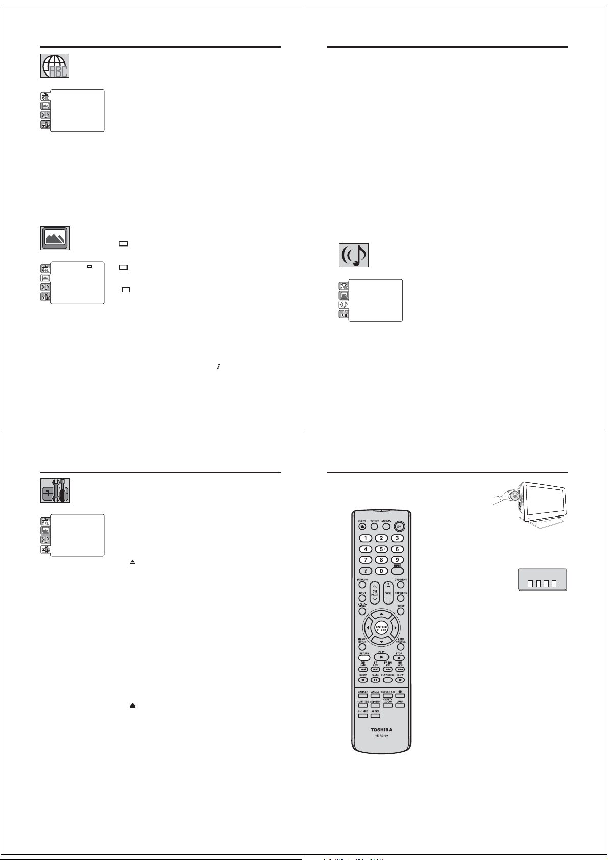
Customizing The Function Settings
Menu, Subtitle, Audio
You can select the language of “Menu”, “Subtitle” and “Audio” if more than
one language is recorded onto the disc.
English, Francais, Espanol, Deutsch, Italiano:
The selected language will be heard or seen.
Parental : Off
DRC : Off
E.B.L. : Off
48
Menu : English
Set Password
QSound : On
TV Screen : 4:3
Subtitle : English
Output : Interlace
Display : On
Audio : English
DivX(R) VOD
Picture Mode : Auto
OSD : English
JPEG Interval : 5 Seconds
Screen Saver : On
Parental : Off
DRC : Off
TV Screen : 16:9
Set Password
QSound : On
Display : On
Output : Interlace
Picture Mode : Auto
DivX(R) VOD
JPEG Interval : Off
Other:
Other languages can be selected (see “Language Code List” on page 52).
Off (Subtitle):
Subtitles do not appear.
Original (Audio):
The unit will select the first priority language of each disc.
Note:
If the selected language is not recorded on the disc, the first- priority
•
language is selected.
Subtitles of Divx
•
Code List in page 52 for the Languages and Codes which able to be set.
OSD
The setup language can be selected.
English: To display OSD language is English
Francais: To display OSD language is French
Espanol: To display OSD language is Spanish
Deutsch: To display OSD language is German
Italiano: To display OSD language is Italian
TV Screen
You have the following screen sizes to choose from:
4:3
When playing back a wide screen-DVD disc, it displays the wide picture
with black bands at the top and bottom of screen.
4:3
It displays the wide picture on the whole screen with left and right edges
automatically cut off.
16:9
A wide screen picture is displayed full size, although the image on the
screen may be geometrically distorted in this mode because the TV
screen has an aspect ratio of 4:3 not 16:9.
Note:
If the DVD disc is not formatted in the pan & scan style, it displays 4:3
•
style.
Display
On screen display can be switched on or off when you press any buttons.
Off: On screen displays do not appear when you press any buttons
On: On screen displays appear when you press the buttons (factory
®
file are also able to be set. Please refer the Language
(Letterbox)
(Panscan)
(Wide screen)
except SUBTITLE, PLAY MODE, MARKER,
JUMP.
setting).
, AUDIO SELECT and
Parental : Off
Menu : English
E.B.L. : Off
Night Mode : Off
Set Password
Subtitle : English
TV Screen : 4:3
Digital Out : Bitstream
Output : Interlace
Audio : English
Display : On
DivX(R)VOD
Picture Mode : Auto
JPEG Interval : 5 Seconds
Screen Saver : On
Customizing The Function Settings
Picture Mode
There are two types of source content in pictures recorded in DVD video
discs: film content (pictures recorded from films at 24 frames per second)
and video content (video signals recorded at 30 frames per second). Make
this selection according to the type of content being viewed.
Auto: Select this selection normally.
The DVD player automatically detects source content, film
or video of playback source, and converts that signal in an
appropriate method.
Film: The DVD player converts film content pictures appropriately.
Suitable for playback of film content pictures.
Video: The DVD player filters video signal, and converts it appropriately.
Suitable for playback of video content pictures.
Note:
Depending on the disc, pictures may be cut off or doubled. In this case,
•
select “Video”.
JPEG Interval
You can continuously playback all JPEG files automatically.
After the selection below, the disc will start playback on JPEG files which
have been recorded.
Off: Plays back one file at a time.
5 Seconds: Plays back images in the form of a slide show at 5 second
10 Seconds: Plays back images in the form of a slide show at 10 second
15 Seconds: Plays back images in the form of a slide show in 15 second
Night Mode
Night Mode enables you to control the dynamic range so as to achieve a
suitable sound for your equipment.
Off: It plays back at the recording level on the disc.
On: Loud sound such as explosion is toned down slightly when played
Note:
•
•
Digital Out
You can select the digital output sound format corresponding to your
system connection.
Off: There is no sound output from DIGITAL AUDIO OUT jack.
PCM: Change Dolby Digital to PCM for the output.
Select when connected to a 2 channel digital stereo
Bitstream: Disc audio bitstream data will be output.
Note:
•
intervals.
intervals.
intervals.
back. This is suitable when it is connected to a stereo.
This function works only when the disc recorded with Dolby Digital is
played back.
The level of Night Mode may differ depending on DVD video disc.
amplifier.
Even if you select “Bitstream”, MPEG Audio will be output in PCM
format.
49
Customizing The Function Settings
Parental
Some discs are specified as not suitable for children. Such discs can be
limited not to playback with the unit.
1) Press or to select “Parental”, then press ENTER. “Enter Password”
screen will appear.
2) Press “0000” using Number buttons (0–9). (Please note, this is pre-
DRC : Off
E.B.L. : Off
Menu : English
Parental : Off
QSound : On
TV Screen : 4:3
Subtitle : English
Password : Change
DivX(R) VOD : Display
Display : On
Audio : English
Picture Mode : Auto
OSD : English
JPEG Interval : 5 Seconds
Screen Saver : On
setting password of this unit). Then press ENTER. The parental level list
will appear.
Level 1: DVD software for adults cannot be played back.
Level 8: Virtually all DVD software can be played back.
Level Off: The parental control setting does not function.
3) Press or to select from the level 1 to level 8. The limitation will be
more severe as the level number is lower. Then press ENTER.
4) Press
to activate Parental control setting.
Note:
If each setup (pages 48 ~ 50) has been completed, the unit can always
•
work under the same condition (especially with DVD discs).
Each setup will be retained in the memory even if you turn the power off.
Depending on the discs, the unit cannot limit playback.
•
Some discs may not be encoded with specific rating level information
•
though its disc jacket says “adult.” For those discs, the age restriction will
not work.
The password is required every time when you change the parental
•
level.
If you input a wrong number, press CANCEL.
•
Password
1) Press or to select “Password”, then press ENTER. “Enter Current
Password” screen will appear.
2) Press Number buttons (0–9) to input the current password (If the
password has not been set yet after you purchase this unit, it is “0000”).
3) Then press ENTER. “Enter New Password” screen will appear. Press
Number buttons (0–9) to input the new password.
4) Press ENTER. Now your new password has been set. Be sure to
remember this number!
If you forget the password.
1) Press
to remove the disc.
2) While holding 7 down on the remote control and at the same time
press STOP (DVD) on the side panel. “Password Clear” appears on
the screen. Now the password has been returned to the initial value
(“0000”).
(R)
DivX
VOD
In order to play DivX® VOD (Video On Demand) content on this unit, you first
need to register the unit with your DivX
generating a DivX
1) Press or to select “DivX(R) VOD”. Then press ENTER.
®
VOD registration code, which you submit to your provider.
Your 8-character registration code is displayed. Make a note of the code as
you will need it when you register with a DivX
ENTER to select Done.
®
VOD content provider. You do this by
®
VOD provider. Then press
Temporary cancel the rating level by DVD disc
Depending on the DVD disc, the
disc may try to temporarily cancel
the rating level that you have set.
It is up to you to decide whether to
cancel the rating level or not.
Note:
•
This temporary cancellation of rating
level will be kept until the disc is
ejected.
When the disc is ejected, the
original rating level will be set again
automatically.
Load a DVD disc.
1
If the DVD disc has been designed to temporarily cancel the
2
Rating level, the screen which follows the “Reading” screen
will change, depending on which disc is played. If you select
“YES” with the ENTER, password input screen will then
appear.
Enter the password with
3
Number buttons (0–9).
Then press ENTER.
To exit from the entry, press
RETURN.
Playback will commence if the entered password was
4
correct.
Enter Password
50
51
Page 18
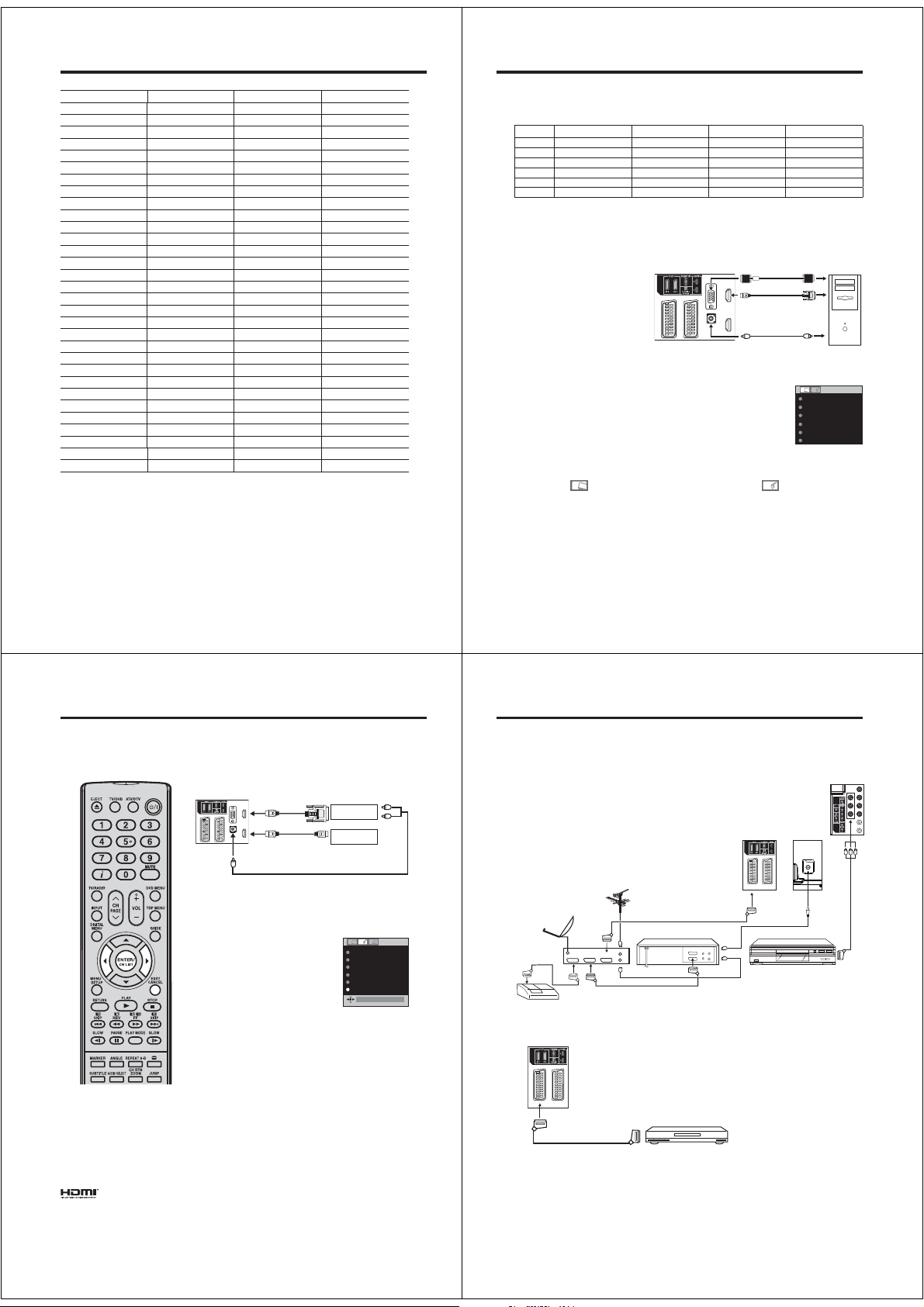
Language Code List
Enter the appropriate code number for the initial settings “Menu”, “Subtitle” and/or “Audio” (see pages 48).
Language Name Code Language Name Code Language Name Code Language Name Code
Abkhazian 1112 Fiji 1620 Lingala 2224 Singhalese 2919
Afar 1111 Finnish 1619 Lithuanian 2230 Slovak* 2921
Afrikaans 1116 French* 1628 Macedonian* 2321 Slovenian* 2922
Albanian* 2927 Frisian 1635 Malagasy 2317 Somali 2925
Amharic 1123 Galician 1722 Malay 2329 Spanish* 1529
Arabic 1128 Georgian 2111 Malayalam 2322 Sundanese 2931
Armenian 1835 German* 1415 Maltese 2330 Swahili 2933
Assamese 1129 Greek* 1522 Maori 2319 Swedish 2932
Aymara 1135 Greenlandic 2122 Marathi 2328 Tagalog 3022
Azerbaijani 1136 Guarani 1724 Moldavian 2325 Tajik 3017
Bashkir 1211 Gujarati 1731 Mongolian 2324 Tamil 3011
Basque 1531 Hausa 1811 Nauru 2411 Tatar 3030
Bengali; Bangla 1224 Hebrew* 1933 Nepali 2415 Telugu 3015
Bhutani 1436 Hindi 1819 Norwegian 2425 Thai 3018
Bihari 1218 Hungarian* 1831 Oriya 2528 Tibetan 1225
Breton 1228 Icelandic 1929 Panjabi 2611 Tigrinya 3019
Bulgarian* 1217 Indonesian 1924 Pashto, Pushto 2629 Tonga 3025
Burmese 2335 Interlingua 1911 Persian 1611 Turkish 3028
Byelorussian* 1215 Irish 1711 Polish* 2622 Turkmen 3021
Cambodian 2123 Italian* 1930 Portuguese 2630 Twi 3033
Catalan 1311 Japanese 2011 Quechua 2731 Ukrainian* 3121
Chinese 3618 Javanese 2033
Corsican 1325 Kannada 2124 Romanian* 2825 Uzbek 3136
Croatian* 1828 Kashmiri 2129 Russian* 2831 Vietnamese 3219
Czech* 1329 Kazakh 2121 Samoan 2923 Volapük 3225
Danish 1411 Kirghiz 2135 Sanskrit 2911 Welsh 1335
Dutch 2422 Korean 2125 Scots Gaelic 1714 Wolof 3325
English* 1524 Kurdish 2131 Serbian* 2928 Xhosa 3418
Esperanto 1525 Laothian 2225 Serbo-Croatian* 2918 Yiddish 2019
Estonian 1530 Latin 2211 Shona 2924 Yoruba 3525
Faroese 1625 Latvian, Lettish 2232 Sindhi 2914 Zulu 3631
Note:
•
Subtitles of Divx
displayed in the languages without *.
®
file are applied to only the languages marked with *. Subtitles of Divx® cannot be
52
Rhaeto-Romance
2823 Urdu 3128
PC connection
As PCs are sometimes supplied with a ‘conventional’ CRT monitor, you may need to adjust the display
settings of your PC’s graphics card, otherwise the pictures may not appear correctly. Switch on your PC (still
with your original monitor) - select ‘1360 x 768’ for the screen resolution, and select 60 Hz for the on-screen
refresh rate. Switch off your PC, then connect it to your LCD TV while both items are still switched off.
Monitor Display modes
MODE Resolution V. Frequency H. Frequency Pixel Clock Frequency
VGA 640 x 480 60.000Hz 31.500kHz 25.200MHz
SVGA 800 x 600 60.317Hz 37.879kHz 40.000MHz
XGA 1024 x 768 60.004Hz 48.363kHz 65.000MHz
WXGA 1280 x 720 59.870Hz 47.776kHz 79.500MHz
WXGA 1280 x 768 59.939Hz 44.955kHz 74.175MHz
WXGA 1360 x 768 60.015Hz 47.712kHz 85.5000MHz
(according to Graphic card)
Select PC input
Switch on the LCD-TV.
Select the PC input mode (see page 11).
(When you use HDMI cable, select HDMI
input mode.)
Note:
•
If there is no video signal from the
computer when the unit is in PC
mode, “NO SIGNAL” will appear on
the TV screen.
•
Digital PC connection via HDMI input
is not supported.
If you try to connect your PC digitally
anyway, the TV-operation might
freeze. TV will stop to respond
properly on usercommands.
Countermeasure: Switch-off
your TV and disconnect from the
220~240V power-supply.
Disconnect the digital PC connection.
Now you may retry operating your TV.
If a digital PC connection does show
•
a picture, proper working is not
guaranteed. Digital PC connection is
not granted for this TV.
Description about the each setting option:
PICTURE Menu
BRIGHTNESS and CONTRAST: You can adjust these
according to your personal preferences.
HOR POSITION and VER POSITION: To adjust the
horizontal and vertical placing of the image.
PHASE and CLOCK: Eliminates the horizontal (PHASE)
and vertical (CLOCK) interfering lines.
RED/GREEN/BLUE: Influences the colour balance.
BACKLIGHT: Press or to adjust the level you require.
WXGA INPUT: When you input an WXGA signal, set this
option to “ON”.
RESET: Press ENTER to reset BRIGHTNESS,
CONTRAST, RED, GREEN, BLUE and BACKLIGHT to the
factory preset values.
Use a PC-VGA cable (not supplied) to connect the LCD-Monitor
to your PC. You can also connect the PC with HDMI cable. If
you use HDMI cable, you don’t have to connect the audio cable.
If you use HDMI-to-DVI cable, please connect audio cable as
same way as VGA cable. Make the connections carefully so as
not to break or bend the contacts inside the plug.
TV (Back side view)
to PC/HDMI1
AUDIO input
to HDMI
input
Audio cable
(not supplied)
VGA cable
(not supplied)
or
to DVI
output
PC
Example: Adjust the contrast.
During PC mode press MENU.
1
The Menu will appear on the screen.
Select CONTRAST, then press
2
ENTER. Press or to adjust
CONTRAST.
Press EXIT to return to the normal screen.
3
AUDIO Menu
BASS/TREBLE/BALANCE: Tone setting
menu.
SURROUND (26DV615DG): Press or to
select surround sound feature ON or OFF.
RESET: Press ENTER to reset BASS,
TREBLE and BALANCE to the factory preset
values.
BRIGHTNESS 25
CONTRAST 40
HOR POSITION 0
VER POSITION
PHASE 25
CLOCK
0
0
53
Connecting an HDMI or a DVI device to the HDMI input
The HDMI (HDMI1)input receives digital audio and uncompressed video from a HDMI equipped device or
uncompressed digital video from a DVI equipped device.
When you connect the HDMI (HDMI1) to a DVI device with a HDMI-to-DVI adapter cable, it only transfers
the video signal, so it is necessary to use separate analogue leads to transfer the audio signals.
Select the HDMI input mode (see page11).
Note:
•
This set is classed as “HD-Ready”.
This means that it is capable of
displaying HD (High Definition)
signals when connected to a suitable
HD source, such as an HD receiver
or DVD player that has HD capability,
via HDMI, DVI, or Component Video
connections.
Some devices may not operate
•
properly with the TV.
HDMI, the HDMI logo and HighDefinition Multimedia Interface are
trademarks or registered trademarks of
HDMI Licensing LLC.
54
TV
(Back side view)
To PC/HDMI1
AUDIO input
Selecting the HDMI audio input source
You must choose the appropriate HDMI audio input setting for
each connection, depending on whether the source is equipped
with a DVI or HDMI socket.
1
2
Note:
•
•
•
(HDMI type A connector) (not supplied)
Select HDMI1 AUDIO (only for
26DV615DG, the rest of the models
are “HDMI AUDIO”) then press
ENTER.
Press or to select HDMI or DVI.
Press EXIT to return to the normal screen.
Follow the user’s manual that came with the HDMI-device,
which you try to connect to this TV.
If there is no picture available via HDMI-connection, do
connect via SCART-cable first. Use the HDMI-device’s
remote-control to call the HDMI-device’s setup-menu onto the
screen.
Follow the HDMI-device’s manual, to set its video-output to
HDMI.
When successfully set to HDMI, select this TV’s HDMI-input,
as described in here on page 11 (Select Video Input).
To DVI
output
HDMI - to - DVI adapter cable
HDMI cable (type A connector)
(not supplied)
To HDMI output
Audio cable
(not supplied)
DVI device
or
HDMI device
NICAM AUTO
BASS 25
TREBLE 25
BALANCE 0
SURROUND OFF
HDMI 1 AUDIOHDMI
HDMI
Connection to other equipment
1. Connecting other units to your TV
Caution. Before connecting:
• Make sure to disconnect the appliance from the power
supply in order to avoid any potential damage from
occurring.
• Make sure to establish the required connection.
• Make sure that connections are properly and correctly
attached before connecting the appliances to the power
supply.
Connect with Satellite receiver as shown below.
Select the TV-Program at the satellite receiver.
To do this, use the remote control of the satellite
receiver. You cannot store the same station once again
additionally in LCD-Monitor which already stored in
satellite receiver.
Antenna
Satellite antenna
DEC
Decoder
Satellite
receiver
VCR
2. Connecting a DVD player
TV (Back side view)
(SCART cable, not supplied)
TV
(All illustrated SCART cables and antenna cables are not supplied)
Video recorder
DVD Player
TV (Back side view)
TV (Back side view)
AV3
ANT.
AV1
To ensure optimum picture quality,
select RGB for the DVD player’s output
signal (see Owner’s manual of the DVD
player). AV1 SCART is compatible with
RGB signal. Select AV1 input mode to
view (see page 11).
ANT
DVD player
55
Page 19
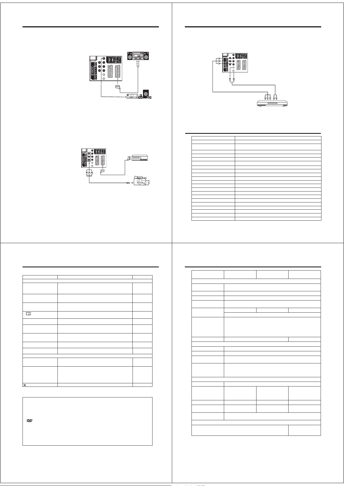
Connection to other equipment
3. Connecting an audio system
You can supply the TV sound to the stereo equipment (A) with the scart socket. Use a special scart cable
for the connection sold separately. (please consult your hi-fi instructions for details). If you have a surround sound amplifier/decoder (B) with a coaxial digital input, you can connect the Coaxial Digital Audio
Output to it, using a suitable coaxial digital lead. This connection carries the audio signal from the set’s
Digital channels only.
Note:
•
The Bass/Treble/Balance adjustments (see
P.18) only function with the sound from the TV
speakers - it does not affect the audio output
sockets.
TV (Back side view)
Stereo amplifier
Audio in put
Connection to other equipment
5. Connecting to a DVD player or other AV device with Component Video outputs
If your DVD player (or other device) has Component Video output jacks, use a suitable set of leads (RCA/
Phono) to connect these to the Component Video inputs on this TV as shown - it can greatly enhance
the picture quality and performance. Please remember that you will also need to connect separate leads
(RCA/Phono) for the audio signals. Select the COMPONENT input mode (see page 11).
(A)
To COMPONENT IN
TV (Back side view)
(Scart-RCA
cable, not
supplied)
(Coaxial digital
lead, not supplied)
•
After connecting a Dolby Digital decoder please select in the DVD menu the Dolby Digital (DD) sound track
option.
•
Several DVDs may be pre-recorded on both sides however only one side contains the Dolby Digital sound
track. Please insert the correct DVD side.
•
When a DTS sound track is played the integrated loudspeakers are mute. The DTS sound can only be
played digitally using the digital outlet. DTS decoder is necessary for hearing.
•
Digital audio output is active only when receiving DVB-T, not when receiving analogue cable TV
broadcasting.
4. Connecting Video camera and Video recorder
Select the AV input mode (see page 11). You can see the playback picture from video camera.
Note:
• If you have a camcorder with S-video, use
an S-video cable instead of a standard
video cable. Do not connect both a standard video cable and an S-video cable at
the same time, or the picture performance
will be unacceptable. (19/22DV615/
616DG)
TV (Back side view)
(AV cable, not supplied)
(SCART cable, not supplied)
Surround sound amplifier
system
AV output
56
Video recorder
Video camera
Audio cable (not supplied)
(B)
Note:
The Component Video input of this unit are for use with equipment which outputs interlaced signals
•
(PAL: 576i/1080i or NTSC: 480i/1080i) and progressive signals (PAL: 576p/720p or NTSC: 480p/720p).
Video cable (not supplied)
Component output
YPbPr
DVD player
Audio output
Status message
Information/Statusmessage Cause
Invalid entry The channel does not exist. (e.g., “000“)
No radio services Cannot change to Radio mode because there is no radio service in the
No TV services Cannot change to TV mode because there is no TV service in the channel list.
No services There are no services in the received signal.
No subtitles There are no subtitles in the received signal.
No video No audio The signal does not contain audio or video.
Audio stream not available The Multi Audio Menu cannot be displayed because there is no sound.
Descrambling not possible The services for the selected channel are not available for this card.
CI card initialized CI card is initializing.
CAM module has been removed CAM module has been removed. (CAM is used for inserting the CI card.)
Database empty There are no services in the TV.
No signal There are no signal inputs.
Locked service The service is locked with the channel organizer.
Scrambled service The service is scrambled and unavailable.
Digital Service Not available.
Not Running Broadcasting has been suspended.
HD service This service is for HD.
New service added … A new service has been added.
Upgrading available service details Service information has been changed. The channel list is updating.
Duplicate carrier found The same signal has already been set.
Invalid Stream Contains a video format that is not supported by this TV.
channel list.
57
Troubleshooting table
Please check the following list before requesting service.
Symptom Possible solution Page
TV
No picture, no sound Switch on the set.
No reception Have you tuned in the TV stations?
The TV switches off with
missing antenna input signal
In
menu, the TUNING
option cannot be selected.
Wrong Colours Colour and Brightness errors can occur when the viewing angle /
While viewing a DVB (digital)
channel, there is sound but no
picture.
Blocky image or image stops
intermittently.
Some digital channels cannot
be viewed.
“Database empty” message
appears on the screen.
DVD
The playback picture has
occasional distortion.
The unit does not start
playback.
appears on the screen.
The LCD panel is a very high technology product, giving you fine picture details. Occasionally, a few nonactive pixels
•
may appear on the screen as a fixed point of blue, green or red. Please note that this does not affect the performance
of your product.
* This product incorporates copyright protection technology that is protected by U.S. patents and other intellectual
property rights. Use of this copyright protection technology must be authorized by Macrovision, and is intended
for home and other limited viewing uses only unless otherwise authorized by Macrovision. Reverse engineering or
disassembly is prohibited.
* Manufactured under license from Dolby Laboratories. Dolby and the double-D symbol are trademarks of Dolby
Laboratories.
*
is a trademark of DVD Format/Logo Licensing Corporation.
* Manufactured under license under U.S. Patent #: 5,451,942 & other U.S. and worldwide patents issued & pending.
DTS and DTS Digital Out are registered trademarks and the DTS logos and Symbol are trademarks of DTS, Inc.
© 1996-2008 DTS, Inc. All Rights Reserved.
* Unauthorized recording of copyrighted television programs, films, video cassettes and other materials may infringe
the rights of copyright owners and be contrary to copyright laws.
* DivX, DivX Certified, and associated logos are trademarks of DivX, Inc. and are used under license.
Check that the mains power outlet is properly connected.
Select appropriate input mode.
Unplug unit for 1 minute, then plug it back in.
Connect the antenna.
Make sure the set is ON and not in Standby mode
This is normal.
15 minutes after the antenna signal has disappeared, the set will
change to standby mode.
The unit is set to AV mode. Press 1 on the remote control. 11
ambient air temperature (see technical specifications) are exceeded.
Some channel offers audio content only. It is normal. –
Check all antenna connections.
Move the antenna away from areas of possible interference.
Try using an antenna booster.
Contact the service provider to subscribe. –
Check all antenna connections and try auto tuning again. 9, 20
The disc is dirty. Eject the disc and clean it.
Some times a small amount of picture distortion may appear. This is
not a malfunction.
No disc is inserted. Insert a disc.
An unplayable disc is inserted. Insert a playable disc (Check the disc
type and colour system).
Place the disc in the disc slot with the label side facing forward.
The disc is dirty. Clean the disc.
Cancel the parental lock function or change the parental lock level.
The function is prohibited with the unit or the disc. 34
10, 11
31, 32
50, 51
Specifications
Model 19DV615DG/
6
9
11
9
6
14
TV
System: Analogue: PAL UK, IR, CCIR, FRENCH System, B/G, D/K, I/I, L
Video Colour System: PAL/SECAM/NTSC 3.58/NTSC 4.43/PAL 60
Preset channels: Analogue channels (99) + Digital channels (Carrier 200/Service1000)
Frequency Range: Analogue: IreE2~E4, X~Z+2, S1~S10, E5~E12, S11~S41, E21~E69
LCD: 470 mm visible* 548 mm visible* 661 mm visible*
–
9
32
31
32
31
HDMI input: HDMI compliant (type A connector)
Audio Output Power: approx. 1.5W (MAX) x 2 approx. 10W (MAX) x 2
DVD
Signal system: NTSC, PAL (Region 2)
Applicable disc: DVD (12cm, 8cm), CD (12cm, 8cm)
Output: Audio : (RCA) –12.0 dBm, 1 k
Pickup: CD : Wavelength: 775 - 805 nm
GENERAL
Power Source: AC 220-240V, 50Hz
Power Consumption: Operation: approx. 38W
Weight: 5.2 kg 5.4 kg 10.3 kg
Dimensions: 47.6(W)x36.4(H)x
Surrounding
temperature:
ACCESSORIES
2 batteries (AAA/R03/UM-4)/Remote control unit/Aerial cable/AC cord 2 batteries (AAA/R03/
Weight and Dimensions are approximate. Because we continually strive to improve our products we may
change specifications and designs without prior notice.
19DV616DG
Digital: DVB-T (OFDM 2k/8k 16QAM/64QAM)
Digital: E5~E12, ItaD~H2, Fra1~6, Rus6~12, E21~E69
TFT low-glass Active Matrix Colour LCD, 1366 x 768 Pixel
HDCP compliant
Suggested scan rates: PAL: 576i/576p/720p/1080i
NTSC: 480i/480p/720p/1080i
PC Audio: 2-channel PCM, 32/44.1/48 kHz sampling frequency
16/20/24 bits per sample
Digital Audio : 0.5Vp-p/75
Maximum output power: 0.5 mW
DVD : Wavelength: 640 - 660 nm
Maximum output power: 1.0 mW
at 230V, 50Hz
Standby: approx. 0.8W
at 230V, 50Hz
20.7(D)cm
Operation: 5°C ~ 40°C/Storage: –20°C ~ 60°C
*Visible screen size is approximate.
22DV615DG/
22DV616DG
Operation: approx. 53W
at 230V, 50Hz
Standby: approx. 0.8W
at 230V, 50Hz
55.0(W)x40.7(H)x
20.7(D)cm
26DV615DG
Operation: approx. 94W
at 230V, 50Hz
Standby: approx. 0.7W
at 230V, 50Hz
68.1(W)x51.4(H)x
22.7(D)cm
UM-4)/Remote control
unit/AC cord
58
59
Page 20
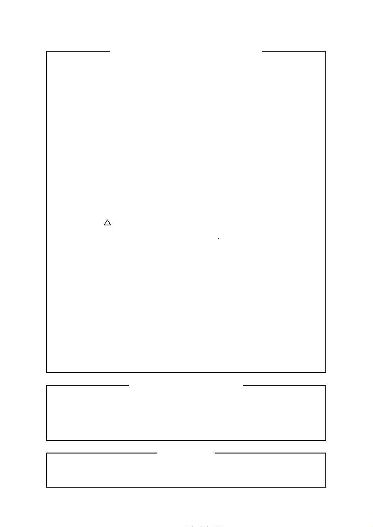
SERVICING NOTICES ON CHECKING
required.
1. KEEP THE NOTICES 6. PERFORM A SAFETY CHECK AFTER
SERVICING
As for the places which need special attentions,
they are indicated with the labels or seals on the Confirm that the screws, parts and wiring which
cabinet, chassis and parts. Make sure to keep the were removed in order to service are put in the
indications and notices in the operation manual. original positions, or whether there are the
portions which are deteriorated around the
2. AVOID AN ELECTRIC SHOCK
There is a high voltage part inside. Avoid an external metal and the AC cord plug blades.
electric shock while the electric current is And be sure the safety of that.
flowing.
3. USE THE DESIGNATED PARTS
The parts in this equipment have the specific 2. Remove the antenna terminal on TV and turn
characters of incombustibility and withstand on the TV.
voltage for safety. Therefore, the part which is 3. Insulation resistance between the cord plug
replaced should be used the part which has terminals and the eternal exposure metal
the same character.
Especially as to the important parts for safety using the 500V insulation resistance meter
which is indicated in the circuit diagram or the
table of parts as a ! mark, the designated 4. If the insulation resistance is less than 1M
parts must be used. ohm, the inspection repair should be
serviced places serviced or not. Check the
insulation between the antenna terminal or
(INSULATION CHECK PROCEDURE)
1. Unplug the plug from the AC outlet.
[Note 2] should be more than 1M ohm by
[Note 1].
4. BE CAREFUL WITH THE
LCD PANEL [Note 1]
If you have not the 500V insulation
Avoid a shock to the panel while servicing. resistance meter, use a Tester.
Take enough care to deal with it.
[Note 2]
5. PUT PARTS AND WIRES IN THE
ORIGINAL POSITION AFTER
ASSEMBLING OR WIRING
There are parts which use the insulation
material such as a tube or tape for safety, or
which are assembled in the condition that
these do not contact with the printed board.
The inside wiring is designed not to get closer
to the pyrogenic parts and high voltage parts.
Therefore, put these parts in the original
positions.
External exposure metal: Antenna terminal
Headphone jack
HOW TO ORDER PARTS
Please include the following informations when you order parts. (Particularly the VERSION LETTER.)
1. MODEL NUMBER and VERSION LETTER
The MODEL NUMBER can be found on the back of each product and the VERSION LETTER can be
found at the end of the SERIAL NUMBER.
2. PART NO. and DESCRIPTION
You can find it in your SERVICE MANUAL.
IMPORTANT
When you exchange IC and Transistor with a heat sink, apply silicon grease (YG6260M) on the contact
section of the heat sink. Before applying new silicon grease, remove all the old silicon grease.
(Old grease may cause damage to the IC and Transistor).
A1-1 19DV616DG/22DV616DG
Page 21
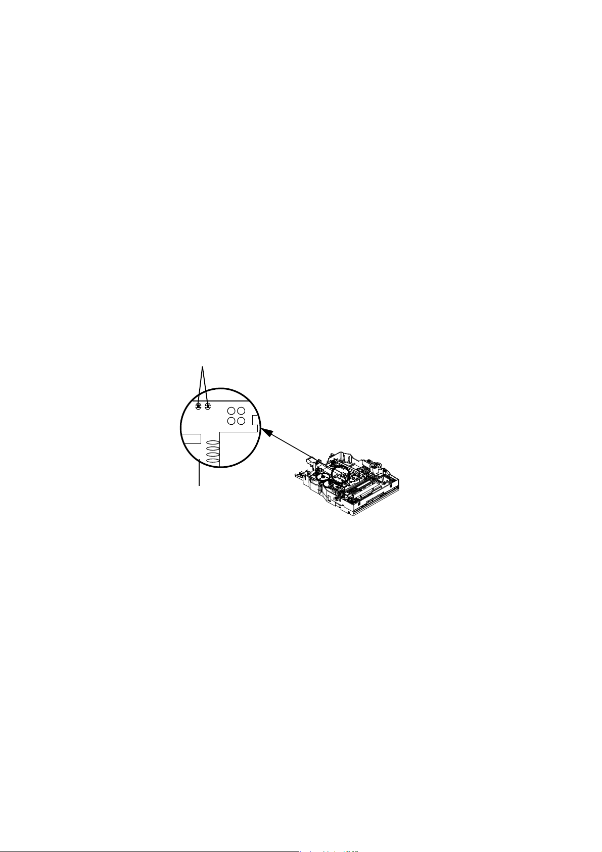
g
WHEN REPLACING DVD DECK
[ When removing the DVD Deck ]
Before removing Pick Up PCB and DVD MT PCB connector, the short circuit the position shown in Fig. 1
using a soldering iron. If you remove the DVD Deck with no soldering, the Laser may be damaged.
[ When installing the DVD Deck ]
Remove all the soldering on the short circuit position after the connection of Pick Up PCB and DVD
MT PCB connector.
NOTE
• Before your operation, please read “PREPARATION OF SERVICING”.
• Use the Lead Free solder.
• Manual soldering conditions
•
Solderin
• Soldering time: Within 3 seconds
• Soldering combination: Sn-3.0Ag-0.5Cu
• When Soldering/Removing of solder, use the draw in equipment over the Pick Up Unit to keep the
Flux smoke away from it.
temperature: 320 ± 20oC
Circuit bridge points
Pick Up PCB
Fig. 1
A1-2 19DV616DG/22DV616DG
Page 22
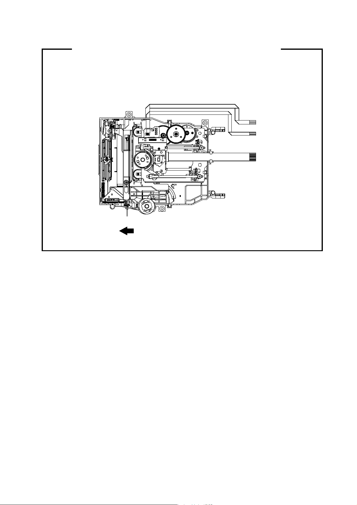
DISC REMOVAL METHOD AT NO POWER SUPPLY
5.Simultaneously press and hold the “7” key on the remote control unit
1. Remove the Stand, Front Cabinet Ass'y and LCD Panel.
(Refer to item 1 of the DISASSEMBLY INSTRUCTIONS.)
2.
Slide the Gear Middle toward the arrow direction by hand to release the lock. (Refer to Fig. 1)
3. Take out the Disc from the DVD Deck. Be careful not to scratch on the Disc.
DVD Deck
Gear Middle
Fig. 1
PARENTAL CONTROL - RATING LEVEL
4 DIGIT PASSWORD CANCELLATION
FOR DVD MODE
If the stored 4 digit password in the Rating Level menu needs to be cancelled, please follow the steps below.
1. Turn Unit ON.
2. Set the DVD to the Stop Mode.
3. Check that “No disc” is displayed on the screen.
4. Press and hold the “STOP” button on the front panel.
.
6. Hold both keys for more than 2 seconds.
7. The On Screen Display message “PASSWORD CLEAR” will appear.
8. The 4 digit password has now been cleared.
FOR DTV MODE
If the stored 4 digit password in the Rating Level menu needs to be cancelled, please follow the steps below.
1. Turn on the power.
2. Set the VOLUME to minimum.
3. Press both VOL. DOWN button on the set and Channel button (3) on the remote control for more than 2 seconds.
4. The 4 digit password has naw been cancelled.
NOTE: No indications on the screen when the Parental Lock is setting.
Initializing password is 0000.
A1-3 19DV616DG/22DV616DG
Page 23
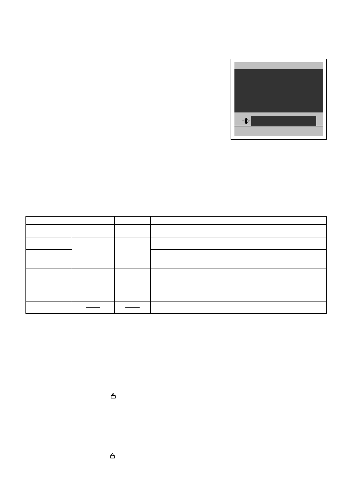
HOTEL MODE FUNCTION
䃂
A
X
䃂
䃂
䃂
䃂
X
To set the Hotel mode, please follow the steps below.
1.
In power on mode, set the VOLUME to minimum.
Press and hold the VOLUME DOWN button on the side panel.
2.
3.
Simultaneously press and hold the channel button (7) on the remote control for more
than 2 seconds.
4.
The Hotel mode setting menu will appear.
5.
Using the UP/DOWN button on the remote control, select the desired mode.
Then press the ENTER button.
Using the LEFT/RIGHT button on the remote control, set the mode to desired setting.6.
7.
The Hotel mode has now been set up.
To set the Hotel mode, please follow the steps below.
1. In power on mode, set the VOLUME to minimum.
2. Press and hold the VOLUME DOWN button on the side panel.
3.
Simultaneously press and hold the channel button (7) on the remote control for more
than 2 seconds.
4. The Hotel mode setting menu will appear.
5. Using the UP/DOWN button on the remote control, select the RESET.
Then press the ENTER button.
6. The setting items has now been returned to initial value.
Setting item
Maximum volume
0~50
Initial valueSetting value
50
Setting of the maximum volume value.
M
PANEL BUT TON
MENU BU T TON
INPUT MODE S TART
RESET
E
IT:END
FUNCTION
HOT E L MOD E
IMUMVOL UME50
RESPOND
RESPOND
OFF
50
Panel button
Menu button
RESPOND/
NO RESPOND
RESPOND
Effective/invalid setting of main key operation. (*Note 1)
Effective/invalid setting of Menu key operation of set and remote control.
(*Note 1)
1~99ch/DTV/AV
COMPONENT/
HDMI/PC/DVD/
OFF
Setting of input source at power supply On. (*Note 2)Input mode start
OFF
Reset Various settings of the Hotel mode function return initial State.
Note 1) Even if setting it to "No Respond", the service mode function are effective.
Note 2) If setting it to "OFF", it start up in same input source when you turn off the power before.
TRAY LOCK
The disk cannot be taken out by setting the Tray Lock, please follow the steps below.
1. Turn Unit ON.
2. Set the DVD to the Stop Mode.
3. Press it in order of "SEPUP", "SUBTITLE", "3", "AUDIO SELECT" and "0" key of a remote control unit.
4. The On Screen Display message " " will appear.
5. The Tray Lock has now been set up.
To unlock the Tray Lock, please follow the steps below.
1. Turn Unit ON.
2. Set the DVD to the Stop Mode.
3. Press it in order of "SETUP", "SUBTITLE", "3", "AUDIO SELECT" and "0" key of a remote control unit.
4. The On Screen Display message " " will appear.
5. The Tray Lock has now been cleared.
A1-4 19DV616DG/22DV616DG
Page 24
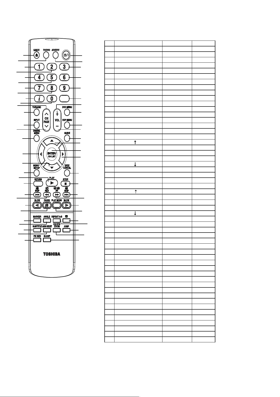
25DIGITAL MENU
40 BF
0A
REMOTE CONTROL KEY CODE
NEC Format
Custom Code : 40-BF H, 44-BB H, 45-BA H, 45-BC H
No. Key Name Custom Code Key Code
1 EJECT 45 BA F5
2 TV/DVD 45 BC B3
3 TV/DTV 40 BF 44
4 POWER 40 BF 12
5 1 40 BF 01
6 2 40 BF 02
7 3 40 BF 03
8 4 40 BF 04
9 5 40 BF 05
10 6 40 BF 06
11 7 40 BF 07
12 8 40 BF 08
13 9 40 BF 09
14 DISPLAY 40 BF 1C
15 0 40 BF 00
16 MUTE 40 BF 10
17 TV/RADIO 40 BF 47
18 CH/PAGE 40 BF 3E
19 VOLUME + 40 BF 1A
20 DVD MENU 40 BF 19
21 INPUT 40 BF 0F
22 CH/PAGE 40 BF 3F
23 VOLUME - 40 BF 1E
24 TOP MENU 44 BB DF
26 GUIDE (EPG) 40 BF 45
27 CH/PAGE 44 BB 80
28 LEFT 44 BB 51
29 ENTER/CHANNEL LIST 40 BF 3D
30 RIGHT 44 BB 4D
31 CH/PAGE 44 BB 81
32 MENU/SETUP 40 BF 0E
33 EXIT/CANCEL 44 BB EF
34 RETURN 44 BB 5D
35 PLAY 44 BB 15
36 STOP 44 BB 14
37 SKIP- /HOLD 45 BA 23
38 REVEAL / SEARCH- 45 BA 19
39 SUB PAGE / SEARCH+ 45 BA 13
40 F/T/B / SKIP+ 45 BA 24
41 RED / SLOW- 45 BA 0E
42 GREEN / PAUSE 45 BA 15
43 YELLOW / PLAY MODE 45 BA E0
44 BLUE / SLOW+ 45 BA 0D
45 MARKER 45 BA EC
46 ANGLE 44 BB 96
47 REPEAT A-B 44 BB 5C
48 TEXT/TV 45 BA 79
49 SUBTITLE 44 BB 87
50 AUDIO SELECT 44 BB 53
51 ZOOM/CH RTN 45 BA 40
52 JUMP 44 BB 9B
53 PICTURE SIZE 40 BF 59
54 SLEEP 40 BF 15
8
A1-5 19DV616DG/22DV616DG
A1-5 19DV616DG/22DV616DG
Page 25
GENERAL SPECIFICATIONS
CH Coverage
Analog
IreE2~E4,X~Z+2,S1~S10,E5~E12,S11~S41,E21~E69
G-1 TV LCD LCD Size / Visual Size 18.5 inch / 470.2mmV
System LCD Type Color TFT LCD
Color System PAL / SECAM
Speaker 2 Speaker
Sound Output MAX 1.5W + 1.5W
NTSC3.58+4.43 /PAL60Hz Yes
G-2 DVD System Color System NTSC, PAL
Disc DVD,
Disc Diameter 120 mm , 80 mm
Drive DSM-3
Search speed Fwd 4 step
Slow speed Fwd 1/7 -1/2 times
G-3 Tuning Broadcasting System Analog
System Tuner and System 1Tuner (Analog+Digital)
Receive CH Destination UK, I.R., CCIR Hyper+France CATV
Number of Pixels 1366(H) x 768(V)
View Range Left/Right 85/85 degree
Bright Dot n=0
Zero Bright Dot Ratio --
Position Front
Size 1.0 x 2.7 inch
Impedance 8 ohm
10%(Typical) ---
Rev 4 step
Rev 1/7 -1/2 times
Digital
Up/Down 80/80 degree
Actual 2-45 times (DVD/Video CD)
Actual 2-45 times (DVD/Video CD)
Actual --
Actual --
<
4-40 times (CD)
4-40 times (CD)
U.K.,
DVB-T
Intermediate Analog
Digital
Frequency Picture(FP) 38.9 / 38.9 / 38.9 / 33.9MHz
Sound(FS)
FP-FS
Digital
Auto Tuning Method
Preset CH Analog 99
Digital Carrier 200 / Service 1000
Stereo/Dual TV Sound Nicam/A2 Dual
Tuner Sound Muting Yes
G-4 Signal Video Signal Input Level 1 V p-p/75 ohm
Output Level 1 V p-p/75 ohm
S/N Ratio (Weighted) 65dB
Horizontal Resolution at DVD Mode 400 Lines
RGB Signal Output Level -Audio Signal Input Level -8.0dBm/50k ohm
Output Level at DVD -12.0dBm/1k ohm (-20dBFs 0dBFs=2.0Vrms)
at TV -8 dBm/1k ohm (0dBm=0.775Vrms)
Digital Output Level 0.5 V p-p/75 ohm
S/N Ratio at DVD (W eighted) 85dB
Harmonic Distortion 0.02% (1KHz)
Frequency Response : at DVD 4Hz - 22kHz
at Video CD 4Hz - 20kHz
at SVCD --
at CD 4Hz - 20kHz
G-5 Power Power Source AC 220-240V AC 50Hz
DC ---
Power Consumption at AC 38 W at AC 230 V 50 Hz
at DC --
Stand by (at AC) w/ EPG Timer 5 W at 230V 50Hz
w/o EPG Timer 0.8 W at 230V 50Hz
Per Year -- kWh/Year
Protector Power Fuse Yes
G-6 Regulation Safety CE(EN60065:2002+AMD.1:2006)
Radiation CE
X-Radiation ---
G-7 Temperature Operation
Storage
Space Around Unit 100 mm(4inch)
G-8 Operating Humidity Less than 80% RH
E5~E12, ItaD~H2, Fra1~6, Rus6~12, E21~E69
BG / II
33.4 / 32.9 / 32.4 / 40.4MHz
5.5 / 6.0 / 6.5 / 6.5MHz
36.167MHz
ALL Band (Not C.C.I.R. CH Plan)
o
C ~ +40oC
+5
o
C ~ +60oC
-20
A2-1 19DV616DG
Page 26
GENERAL SPECIFICATIONS
8
Yes
G-9 OSD Language (TV) English, Spanish, German, French, Italian,
(DVD) English, Spanish, German, French, Italian
G-10 Clock and Sleep Timer Max Time 120 Min
Timer Step 10 Min
On/Off Timer Program(On Timer / Off Timer) -- Program
Wake Up Timer No
Timer Back-up (at Power Off Mode) more than -- Min Sec
EPG Timer Events 8Programs / 8Days
G-11 Remote Unit RC-QJ
Control Glow in Dark Remocon No
Remocon Format TOSHIBA
Format TOSHIBA
Custom Code 40-BF h ,44-BB h ,45-BA h ,45-BC h
Power Source Voltage(D.C) 3V
UM size x pcs UM-4 x 2 pcs
Total Keys 54 Keys
Keys Power (Stand By) Yes
Information/(Display) Yes
Analog Menu / Setup Yes
Digital Menu Yes
Input Select Yes
ATV/DTV Yes
Guide/(EPG) Yes
Picture Size Yes
1Yes
2Yes
3Yes
4Yes
5Yes
6Yes
7Yes
Swedish, Dutch, Russian, Portuguese,
Turkish, Greek, Finnish, Polish, Danish, Norwegian
9Yes
0 Yes
Sleep Yes
Mute Yes
Volume Up Yes
Volume Down Yes
Enter / CH List Yes
Exit / Cancel Yes
Freeze frame No
TV/Radio Yes
Subtitle Yes
Play Yes
Stop Yes
Eject Yes
TV / DVD Yes
Return Yes
DVD Menu Yes
Top Menu Yes
Marker Yes
Angle Yes
Repeat A-B Yes
Audio Select Yes
CH RTN(Quick View) / Zoom Yes
Jump Yes
T'TEXT Keys TEXT / TV Yes
HOLD / Skip- Yes
Reveal / Search- Yes
Sub Page / Search+ Yes
F.T.B / Skip+ Yes
Red / Slow- Yes
Green / Pause Yes
Yellow / Play Mode Yes
Cyan / Slow+ Yes
CH Up / Page Up Yes
CH Down / Page Down Yes
Yes
Yes
Yes
Yes
A2-2 19DV616DG
Page 27
GENERAL SPECIFICATIONS
Surround
No
G-12 Features Power On Memory Yes
Auto Shut Off Yes
Just Clock Function No
Game Position No
DNR Yes
3D
Comb Filter Yes
3D
Auto Set Up (Fast installation) Auto tuning (Analog tuner) Yes
CH sort Yes
ATS Yes
Auto clock (Analog tuner) No
Plug in start Yes
Picture Setting(TV) Picture Preference Yes
Brightness , Contrast , Color Yes
Tint Yes
Sharpness Yes
DNR No
Color Temperature Yes
Blue Back Yes
Backlight Control Yes
DBC (Dynamic Backlight Control) No
Film Mode No
Picture Setting(PC) BRIGHTNESS , CONTRAST Yes
HOR POSITION , VER POSITION Yes
PHASE , CLOCK Yes
AUTO ADJUST No
RED , GREEN , BLUE Yes
Backlight Yes
WXGA INPUT Yes
WVGA INPUT No
Audio Nicam Yes
Tone Control (Bass/Treble/Balance) Yes
BBE No
SRS WOW (SRS 3D/Focus/Tru Bass) No
Tuning Auto Tuning Yes
Lock (Analog) Panel Lock No
Screen Saver
Black Side Panel No
CH Label Yes
T'Text Yes
Text and Picture Yes
Wide Mode (AUTO/4:3/16:9/CINEMA/14:9/REAL(HDMI Only) Yes
Reset TV Setting Yes
HD Zoom No
Picture Scroll (Vertical Position) Yes
PFC(Power Factor circuit) No
Freeze frame No
HD-Ready Yes
Plug and Play No
Brand Badge LED No
Scart Spec Scart1 AV in Yes
Scart2 AV in No
Variable Audio Out No
Manual Tuning Yes
CH Allocation Yes
Channel Lock No
Hotel Lock Yes
Inversion No
Full W hit e No
Screen Saver No
Static Image No
Text type Fastext / Toptext
Text Language English , French, Swedish, Hungarian
Turkish, German, Portuguese, Spanish,
Italian, Greek, Slovakian, Russian, Polish,
Czech, Rumanian, Estonian, Lettish,
Lithuanian, Ukrainian, Croatian, Slovenian,
Latvian
AV out Yes (A.Tuner/D.Tuner/Monitor)
S-Video in No
RGB in Yes
AV out No
S-Video in No
RGB in No
A2-3 19DV616DG
Page 28
GENERAL SPECIFICATIONS
720×576i (4:3)
Yes (50Hz)
Digital Text (VBI teletext)
MHEG-5
MHP
EPG (BBC type 8Days Digital tuner only)
OAD (Over Air Download)
Common Interface (Digital tuner only)
Rec Screen Status
Ch sorting based on Ch List (Digital/Germany only)
Rename Carrier (Digital)
Edit Event Timer
Software Update via CI Slot
Preference Language (Audio/Subtitle/Digital Service)(Digital)
Ch Organizer (Lock, Skip, Go To, Delete, Rename, Move, Move to, Change No.)
Parental Lock (Digital)
Time Setup
DVB Subtitle (Digital)
AC3 Audio Out (Output via SPDIF Only)
PC Monitor Input Yes
VGA (640x480) Yes (60Hz)
VGA (720x400) No (Possible to Display)
WVGA (848x480) No
SVGA (800x600) Yes (60Hz)
XGA (1024x768) Yes (60Hz)
WXGA (1280x768) Yes (60Hz)
WXGA (1280x720) Yes (60Hz)
WXGA (1360x768) Yes (60Hz)
SXGA (1280x1024) No
HDMI Input Yes
VGA (640×480) Yes (60Hz)
720×480i (4:3) Yes (60Hz)
720×480i (16:9) Yes (60Hz)
720×480p (4:3) Yes (60Hz)
720×480p (16:9) Yes (60Hz)
Yes
Yes
Yes
Yes
Yes
Yes
Yes
Yes
Yes
Yes
Yes
Yes
Yes
Yes
Yes
Yes
No
720×576i (16:9) Yes (50Hz)
720×576p (4:3) Yes (50Hz)
720×576p (16:9) Yes (50Hz)
1280×720p Yes (50/60Hz)
Component Input Yes
Wall Mount Size W x H(mm) Yes (100 x 100)
Stand Tilt Yes
Features Tray Lock Yes
(DVD) WMA No
JPEG Yes
Video CD Playback Yes
SVCD Playback No
MP3 Playback Yes
Divx Playback Yes
Digital Out (Dolby Digital) Yes
Down Mix Out (Dolby Digital) Yes
3D Surround No
Closed Caption No
Screen Saver No
Audio DAC 192kHz / 24bit
Macrovision Yes
1920×1080i Yes (50/60Hz)
720×480i (4:3) Yes (60Hz)
720×480i (16:9) Yes (60Hz)
720×480p (4:3) Yes (60Hz)
720×480p (16:9) Yes (60Hz)
720×576i (4:3) Yes (50Hz)
720×576i (16:9) Yes (50Hz)
720×576p (4:3) Yes (50Hz)
720×576p (16:9) Yes (50Hz)
1280×720p Yes (50/60Hz)
1920×1080i Yes (50/60Hz)
Screw Size M4 x 10
Swievel No
DMF Support No
(MPEG) Yes
(PCM) Yes
(DTS) Yes
(DTS) No
A2-4 19DV616DG
Page 29
GENERAL SPECIFICATIONS
300 ohm to 75 ohm Antenna Adapter
No
G-13 Accessories Owner's Manual (Full) Language English, French, German
(Simplified)
w/Guarantee Card No
Remote Control Unit Yes
Rod Antenna No
Poles Terminal -
Loop Antenna (W/ Antenna Change Plug) No
Terminal -
U/V Mixer No
DC Car Cord (Center+) No
Guarantee Card No
Warning Sheet No
Registration Card No
Circuit Diagram No
Antenna Change Plug No
Service Facility List No
Important Safeguard No
Dew/AHC Caution Sheet No
Quick Set-up Sheet Yes
My Movie stream (Free DVD redemption voucher) No
Carbon Neutral Certificate No
Battery Yes
UM size x pcs UM-4 x 2 pcs
OEM Brand No
AC Adapter No
AC Cord (for AC Adapter) No
AC Cord Yes
AV Cord (2Pin-1Pin) No
RF Cable Yes
HDMI-DVI Cable No
Helpline Sheet No
Italian, Spanish, Dutch, Danish, Norwegian, Swedish,
Finnish, Czech, Greek
G-14 Interface Switch Side Power (Tact) Yes
Indicator Power/Stand-by/EPG Timer Yes(GREEN / RED / ORANGE)
Terminals Side CI Card Slot Yes
Rear Video Input 1
System Select No
Main Power SW No
Channel Up / Play / Menu Up Yes
Channel Down / STOP / Menu Down Yes
Volume Up / Menu> Yes
Volume Down / Menu< Yes
Play No (CH+ Alternative)
Eject Yes
Skip+, Search+ No
Skip-, Search- No
Stop No (CH- Alternative)
Input Select / Enter Yes
Menu Yes
On Timer No
Audio Input 1
S- Input 1 Yes (AV2)
Video Input 2 No
Audio Input 2 No
S- Input 2 No
Video Output No
Audio Output No
Digital Audio Out (Coaxial)
Component In
Audio Input (Component In use)
Sub Woofer Output No
Diversity No
Ext Speaker No
DC Jack 12V(Center +) No
Other Terminal Headphone
VHF/UHF Antenna Input
AC Inlet
Euro Scart (21Pin)
PC Monitor Input (D-Sub)
Audio Input
HDMI Input 1
Audio Input (HDMI/DVI In use) PC Monitor Audio Input Alternative
HDMI Input 2 No
Audio Input (HDMI/DVI In use) No
RCA x 1 (AV2)
RCA x 2(L/MONO, R) (AV2)
Yes
RCA x 3
RCA x 2(L/MONO, R)
DIN Type
Yes
1Scart (AV1)
Yes
Mini Pin Jack( 3.5), STEREO
Yes
A2-5 19DV616DG
Page 30
GENERAL SPECIFICATIONS
G-15 Set Size Approx. W x D x H (mm) 476 x 207 x 364
G-16 Weight Net Approx. 5.2kg (11.5lbs)
G-17 Carton Master Carton No
Gift Box Yes
Drop Test 6 Surfaces
Container Stuffing 1140 Sets/40' container
w/Pallet Yes
w/Wrapping Yes
G-18 Material Cabinet Cabinet Front PS 94V0 NON-DECABROM
PCB Non-Halogen No
G-19 Environment Environmental standard requirement Green procurement of TOSHIBA
Pb- Free Phase3(PHASE3A)
WEEE Yes
w/o Stand,Handle Approx. W x D x H (mm)
Net w/o Stand,Handle Approx. 4.5kg (9.9bs)
Gross Approx. 6.9kg (15.2 lbs)
Gross w/Master Carton (Approx.) --- kg ( --- lbs)
Content ---- Sets
Material -- /-Dimensions W x D x H(mm) -- x -- x --
Description of Origin No
Material Double/Full Color
Dimensions W x D x H(mm) 562 x 535 x 181
W/Handle Yes
W/Color Photo Label No
Description of Origin Yes
Height (cm) 80
Cabinet Rear PS 94V0 NON-DECABROM
Eyelet Yes
Measures for Whisker Yes
476 x 66.8 x 333.2
A2-6 19DV616DG
Page 31

GENERAL SPECIFICATIONS
CH Coverage
Analog
IreE2~E4,X~Z+2,S1~S10,E5~E12,S11~S41,E21~E69
G-1 TV LCD LCD Size / Visual Size 21.60 inch / 547.7mmV
System LCD Type Color TFT LCD
Color System PAL / SECAM
Speaker 2 Speaker
Sound Output MAX 1.5W + 1.5W
NTSC3.58+4.43 /PAL60Hz Yes
G-2 DVD System Color System NTSC, PAL
Disc DVD,
Disc Diameter 120 mm , 80 mm
Drive DSM-3
Search speed Fwd 4 step
Slow speed Fwd 1/7 -1/2 times
G-3 Tuning Broadcasting System Analog
System Tuner and System 1Tuner (Analog+Digital)
Receive CH Destination UK, I.R., CCIR Hyper+France CATV
Number of Pixels 1366(H) x 768(V)
View Range Left/Right 85/85 degree
Bright Dot n=0
Zero Bright Dot Ratio --
Position Front
Size 1.0 x 2.7 inch
Impedance 8 ohm
10%(Typical) ---
Rev 4 step
Rev 1/7 -1/2 times
Digital
Up/Down 80/80 degree
Actual 2-45 times (DVD/Video CD)
Actual 2-45 times (DVD/Video CD)
Actual --
Actual --
<
4-40 times (CD)
4-40 times (CD)
U.K.,
DVB-T
Intermediate Analog
Digital E5~E12, ItaD~H2, Fra1~6, Rus6~12, E21~E69
Frequency Picture(FP) 38.9 / 38.9 / 38.9 / 33.9MHz
Sound(FS)
FP-FS
Digital
Auto Tuning Method
Preset CH Analog 99
Digital Carrier 200 / Service 1000
Stereo/Dual TV Sound Nicam/A2 Dual
Tuner Sound Muting Yes
G-4 Signal Video Signal Input Level 1 V p-p/75 ohm
Output Level 1 V p-p/75 ohm
S/N Ratio (Weighted) 65dB
Horizontal Resolution at DVD Mode 400 Lines
RGB Signal Output Level -Audio Signal Input Level -8.0dBm/50k ohm
Output Level at DVD -12.0dBm/1k ohm (-20dBFs 0dBFs=2.0Vrms)
at TV -8 dBm/1k ohm (0dBm=0.775Vrms)
Digital Output Level 0.5 V p-p/75 ohm
S/N Ratio at DVD (W eighted) 85dB
Harmonic Distortion 0.02% (1KHz)
Frequency Response : at DVD 4Hz - 22kHz
at Video CD 4Hz - 20kHz
at SVCD --
at CD 4Hz - 20kHz
G-5 Power Power Source AC 220-240V AC 50Hz
DC ---
Power Consumption at AC 53 W at AC 230 V 50 Hz
at DC --
Stand by (at AC) w/ EPG Timer 5 W at 230V 50Hz
w/o EPG Timer 0.8 W at 230V 50Hz
Per Year -- kW h/Year
Protector Power Fuse Yes
G-6 Regulation Safety CE(EN60065:2002+AMD.1:2006)
Radiation CE
X-Radiation ---
G-7 Temperature Operation
Storage
Space Around Unit 100 mm(4inch)
G-8 Operating Humidity Less than 80% RH
BG / II
33.4 / 32.9 / 32.4 / 40.4MHz
5.5 / 6.0 / 6.5 / 6.5MHz
36.167MHz
ALL Band (Not C.C.I.R. CH Plan)
o
C ~ +40oC
+5
o
C ~ +60oC
-20
A2-7 22DV616DG
Page 32

GENERAL SPECIFICATIONS
8
Yes
G-9 OSD Language (TV) English, Spanish, German, French, Italian,
(DVD) English, Spanish, German, French, Italian
G-10 Clock and Sleep Timer Max Time 120 Min
Timer Step 10 Min
On/Off Timer Program(On Timer / Off Timer) -- Program
Wake Up Timer No
Timer Back-up (at Power Off Mode) more than -- Min Sec
EPG Timer Events 8Programs / 8Days
G-11 Remote Unit RC-QJ
Control Glow in Dark Remocon No
Remocon Format TOSHIBA
Format TOSHIBA
Custom Code 40-BF h ,44-BB h ,45-BA h ,45-BC h
Power Source Voltage(D.C) 3V
UM size x pcs UM-4 x 2 pcs
Total Keys 54 Keys
Keys Power (Stand By) Yes
Information/(Display) Yes
Analog Menu / Setup Yes
Digital Menu Yes
Input Select Yes
ATV/DTV Yes
Guide/(EPG) Yes
Picture Size Yes
1Yes
2Yes
3Yes
4Yes
5Yes
6Yes
7Yes
Swedish, Dutch, Russian, Portuguese,
Turkish, Greek, Finnish, Polish, Danish, Norwegian
9Yes
0 Yes
Sleep Yes
Mute Yes
Volume Up Yes
Volume Down Yes
Enter / CH List Yes
Exit / Cancel Yes
Freeze frame No
TV/Radio Yes
Subtitle Yes
Play Yes
Stop Yes
Eject Yes
TV / DVD Yes
Return Yes
DVD Menu Yes
Top Menu Yes
Marker Yes
Angle Yes
Repeat A-B Yes
Audio Select Yes
CH RTN(Quick View) / Zoom Yes
Jump Yes
T'TEXT Keys TEXT / TV Yes
HOLD / Skip- Yes
Reveal / Search- Yes
Sub Page / Search+ Yes
F.T.B / Skip+ Yes
Red / Slow- Yes
Green / Pause Yes
Yellow / Play Mode Yes
Cyan / Slow+ Yes
CH Up / Page Up Yes
CH Down / Page Down Yes
Yes
Yes
Yes
Yes
A2-8 22DV616DG
Page 33

GENERAL SPECIFICATIONS
Surround
No
G-12 Features Power On Memory Yes
Auto Shut Off Yes
Just Clock Function No
Game Position No
DNR Yes
3D
Comb Filter Yes
3D
Auto Set Up (Fast installation) Auto tuning (Analog tuner) Yes
CH sort Yes
ATS Yes
Auto clock (Analog tuner) No
Plug in start Yes
Picture Setting(TV) Picture Preference Yes
Brightness , Contrast , Color Yes
Tint Yes
Sharpness Yes
DNR No
Color Temperature Yes
Blue Back Yes
Backlight Control Yes
DBC (Dynamic Backlight Control) No
Film Mode No
Picture Setting(PC) BRIGHTNESS , CONTRAST Yes
HOR POSITION , VER POSITION Yes
PHASE , CLOCK Yes
AUTO ADJUST No
RED , GREEN , BLUE Yes
Backlight Yes
WXGA INPUT Yes
WVGA INPUT No
Audio Nicam Yes
Tone Control (Bass/Treble/Balance) Yes
BBE No
SRS WOW (SRS 3D/Focus/Tru Bass) No
Tuning Auto Tuning Yes
Lock (Analog) Panel Lock No
Screen Saver
Black Side Panel No
CH Label Yes
T'Text Yes
Text and Picture Yes
Wide Mode (AUTO/4:3/16:9/CINEMA/14:9/REAL(HDMI Only) Yes
Reset TV Setting Yes
HD Zoom No
Picture Scroll (Vertical Position) Yes
PFC(Power Factor circuit) No
Freeze frame No
HD-Ready Yes
Plug and Play No
Brand Badge LED No
Scart Spec Scart1 AV in Yes
Scart2 AV in No
Variable Audio Out No
Manual Tuning Yes
CH Allocation Yes
Channel Lock No
Hotel Lock Yes
Inversion No
Full W hit e No
Screen Saver No
Static Image No
Text type Fastext / Toptext
Text Language English , French, Swedish, Hungarian
Turkish, German, Portuguese, Spanish,
Italian, Greek, Slovakian, Russian, Polish,
Czech, Rumanian, Estonian, Lettish,
Lithuanian, Ukrainian, Croatian, Slovenian,
Latvian
AV out Yes (A.Tuner/D.Tuner/Monitor)
S-Video in No
RGB in Yes
AV out No
S-Video in No
RGB in No
A2-9 22DV616DG
Page 34

GENERAL SPECIFICATIONS
720×576i (4:3)
Yes (50Hz)
Digital Text (VBI teletext)
MHEG-5
MHP
EPG (BBC type 8Days Digital tuner only)
OAD (Over Air Download)
Common Interface (Digital tuner only)
Rec Screen Status
Ch sorting based on Ch List (Digital/Germany only)
Rename Carrier (Digital)
Edit Event Timer
Software Update via CI Slot
Preference Language (Audio/Subtitle/Digital Service)(Digital)
Ch Organizer (Lock, Skip, Go To, Delete, Rename, Move, Move to, Change No.)
Parental Lock (Digital)
Time Setup
DVB Subtitle (Digital)
AC3 Audio Out (Output via SPDIF Only)
PC Monitor Input Yes
VGA (640x480) Yes (60Hz)
VGA (720x400) No (Possible to Display)
WVGA (848x480) No
SVGA (800x600) Yes (60Hz)
XGA (1024x768) Yes (60Hz)
WXGA (1280x768) Yes (60Hz)
WXGA (1280x720) Yes (60Hz)
WXGA (1360x768) Yes (60Hz)
SXGA (1280x1024) No
HDMI Input Yes
VGA (640×480) Yes (60Hz)
720×480i (4:3) Yes (60Hz)
720×480i (16:9) Yes (60Hz)
720×480p (4:3) Yes (60Hz)
720×480p (16:9) Yes (60Hz)
Yes
Yes
Yes
Yes
Yes
Yes
Yes
Yes
Yes
Yes
Yes
Yes
Yes
Yes
Yes
Yes
No
720×576i (16:9) Yes (50Hz)
720×576p (4:3) Yes (50Hz)
720×576p (16:9) Yes (50Hz)
1280×720p Yes (50/60Hz)
Component Input Yes
Wall Mount Size W x H(mm) Yes (100 x 100)
Stand Tilt Yes
Features Tray Lock Yes
(DVD) WMA No
JPEG Yes
Video CD Playback Yes
SVCD Playback No
MP3 Playback Yes
Divx Playback Yes
Digital Out (Dolby Digital) Yes
Down Mix Out (Dolby Digital) Yes
3D Surround No
Closed Caption No
Screen Saver No
Audio DAC 192kHz / 24bit
Macrovision Yes
1920×1080i Yes (50/60Hz)
720×480i (4:3) Yes (60Hz)
720×480i (16:9) Yes (60Hz)
720×480p (4:3) Yes (60Hz)
720×480p (16:9) Yes (60Hz)
720×576i (4:3) Yes (50Hz)
720×576i (16:9) Yes (50Hz)
720×576p (4:3) Yes (50Hz)
720×576p (16:9) Yes (50Hz)
1280×720p Yes (50/60Hz)
1920×1080i Yes (50/60Hz)
Screw Size M4 x 10
Swievel No
DMF Support No
(MPEG) Yes
(PCM) Yes
(DTS) Yes
(DTS) No
A2-10 22DV616DG
Page 35

GENERAL SPECIFICATIONS
300 ohm to 75 ohm Antenna Adapter
No
G-13 Accessories Owner's Manual (Full) Language English, French, German
(Simplified)
w/Guarantee Card No
Remote Control Unit Yes
Rod Antenna No
Poles Terminal -
Loop Antenna (W/ Antenna Change Plug) No
Terminal -
U/V Mixer No
DC Car Cord (Center+) No
Guarantee Card No
Warning Sheet No
Registration Card No
Circuit Diagram No
Antenna Change Plug No
Service Facility List No
Important Safeguard No
Dew/AHC Caution Sheet No
Quick Set-up Sheet Yes
My Movie stream (Free DVD redemption voucher) No
Carbon Neutral Certificate No
Battery Yes
UM size x pcs UM-4 x 2 pcs
OEM Brand No
AC Adapter No
AC Cord (for AC Adapter) No
AC Cord Yes
AV Cord (2Pin-1Pin) No
RF Cable Yes
HDMI-DVI Cable No
Helpline Sheet No
Italian, Spanish, Dutch, Danish, Norwegian, Swedish,
Finnish, Czech, Greek
G-14 Interface Switch Side Power (Tact) Yes
Indicator Power/Stand-by/EPG Timer Yes(GREEN / RED / ORANGE)
Terminals Side CI Card Slot Yes
Rear Video Input 1
System Select No
Main Power SW No
Channel Up / Play / Menu Up Yes
Channel Down / STOP / Menu Down Yes
Volume Up / Menu> Yes
Volume Down / Menu< Yes
Play No (CH+ Alternative)
Eject Yes
Skip+, Search+ No
Skip-, Search- No
Stop No (CH- Alternative)
Input Select / Enter Yes
Menu Yes
On Timer No
Audio Input 1
S- Input 1 Yes (AV2)
Video Input 2 No
Audio Input 2 No
S- Input 2 No
Video Output No
Audio Output No
Digital Audio Out (Coaxial)
Component In
Audio Input (Component In use)
Sub Woofer Output No
Diversity No
Ext Speaker No
DC Jack 12V(Center +) No
Other Terminal Headphone
VHF/UHF Antenna Input
AC Inlet
Euro Scart (21Pin)
PC Monitor Input (D-Sub)
Audio Input
HDMI Input 1
Audio Input (HDMI/DVI In use) PC Monitor Audio Input Alternative
HDMI Input 2 No
Audio Input (HDMI/DVI In use) No
RCA x 1 (AV2)
RCA x 2(L/MONO, R) (AV2)
Yes
Yes
RCA x 2(L/MONO, R)
DIN Type
Yes
1Scart (AV1)
Yes
Mini Pin Jack( 3.5), STEREO
Yes
A2-11 22DV616DG
Page 36

GENERAL SPECIFICATIONS
G-15 Set Size Approx. W x D x H (mm) 550.0 x 207.0 x 407.1
G-16 Weight Net Approx. 5.4kg (11.9lbs)
G-17 Carton Master Carton No
Gift Box Yes
Drop Test 6 Surfaces
Container Stuffing 984 Sets/40' container
w/Pallet Yes
w/Wrapping Yes
G-18 Material Cabinet Cabinet Front PS 94V0 NON-DECABROM
PCB Non-Halogen No
G-19 Environment Environmental standard requirement Green procurement of TOSHIBA
Pb- Free Phase3(PHASE3A)
WEEE Yes
w/o Stand,Handle Approx. W x D x H (mm)
Net w/o Stand,Handle Approx. 4.8kg (10.6lbs)
Gross Approx. 7.6kg (16.7 lbs)
Gross w/Master Carton (Approx.) --- kg ( --- lbs)
Content ---- Sets
Material -- /-Dimensions W x D x H(mm) -- x -- x --
Description of Origin No
Material Double/Full Color
Dimensions W x D x H(mm) 622 x 575 x 181
W/Handle Yes
W/Color Photo Label No
Description of Origin Yes
Height (cm) 80
Cabinet Rear PS 94V0 NON-DECABROM
Eyelet Yes
Measures for Whisker Yes
550.0 x 66.8 x 376.2
A2-12 22DV616DG
Page 37

DISASSEMBLY INSTRUCTIONS
1. REMOVAL OF MECHANICAL PARTS
AND P.C. BOARDS
CAUTION
Be careful not to remove the FFC cable forcibly, because
the FFC cable may be damaged.
1-1: STAND ASS'Y (Refer to Fig. 1-1)
1. Remove the 2 screws (1).
2. Remove the Stand Ass'y in the direction of arrow.
(1)
(1)
Stand Ass'y
1-3: FRONT CABINET ASS'Y and LCD PANEL
(Refer to Fig. 1-3)
1. Turn up set and put the Front Cabinet Ass'y of LCD
on the top.
2. Remove the Front Cabinet Ass'y in the direction of
arrow (A).
3.
Disconnect the following connector: (CD7201).
4. Remove the LCD Panel in the direction of arrow (B).
Front Cabinet Ass'y
(A)
Fig. 1-1
1-2: COVER INVERTER (Refer to Fig. 1-2)
1. Remove the screw (1).
2. Remove the Cover Inverter in the direction of arrow (A).
3. Disconnect the following connectors:
(CP7001 and CP7002).
4. Unlock the support (2).
5. Remove the Cover AC in the direction of arrow (B).
6. Remove the 10 screws (3).
(1)
Cover Inverter
(3)
(3)
(3)
(3)
(3)
(3)
(3)
(A)
(3)
Cover AC
(2)
(B)
(3)
(3)
CD7201
(LVDS Cable)
LCD Panel
(B)
CP7001
CP7002
Fig. 1-2
Back Cabinet Ass'y
Fig. 1-3
B1-1 19DV616DG
B1-1 19DV616DG
Page 38

DISASSEMBLY INSTRUCTIONS
g
0
DVD Deck Ass y
1-4: DVD MT PCB and DVD DECK (Refer to Fig. 1-4) 1-5: POWER PCB and REMOCON PCB (Refer to Fig. 1-5)
1. Put the Back Cabinet Ass'y on the bottom. 1. Remove the 2 screws (1).
2.
Short circuit the position shown in Fig. 1-4 using a
soldering iron. If you remove the DVD Deck with no 3. Remove the 6 screws (2).
soldering, the Laser may be damaged. 4. Disconnect the following connector:
3. Disconnect the following connectors:
(CP2301, CP2302, CP2305, CP8501 and CP8502).
4. Remove the 3 screws (1). 6.
5. Remove the DVD DECK Ass'y in the direction of 7. Remove the screw (3).
arrow (A). 8. Remove the Remocon PCB in the direction of arrow (C).
6. Remove the 2 screws (2).
7. Remove the Shield LVDS in the direction of arrow (B).
8. Unlock the 2 supports (3).
9. Remove the DVD MT PCB in the direction of arrow (C).
(2)
(2)
Shield LVDS
CP2302
CP8502
CP8501
DVD MT PCB
(B)
(C)
'
(1)
CP2305
CP2301
(3)
(1)
Pick Up PCB
(1)
2. Remove the Plate PCB in the direction of arrow (A).
(CP501 and CP8101).
5. Remove the Power PCB in the direction of arrow (B).
Disconnect the following connector: (CP7601).
(1)
(1)
(2)
Power PCB
(2)
(2)
(2)
(2)
(2)
CP501
(B)
(A)
CP8101
Plate PCB
Remocon PCB
(3)
(C)
CP7601
(A)
Short circuit using a
Back Cabinet Ass'y
soldering iron.
1-6: MAIN PCB and TUNER PCB (Refer to Fig. 1-6)
Back Cabinet Ass'y
Fig. 1-4
1. Remove the 2 screws (1).
2.
Disconnect the following connector: (CP5803).
3. Remove the Tuner PCB in the direction of arrow (A).
NOTE
4. Remove the 4 screws (2).
5. Disconnect the following connector:
1. Before your operation, please read "PREPARATION
(CP2201 and CP5801).
OF SERVICING". 6. Remove the Main PCB in the direction of arrow (B).
2. Use the Lead Free solder.
3. Manual soldering conditions
• Solderin
temperature: 320 ± 2
o
C
• Soldering time: Within 3 seconds
• Soldering combination: Sn-3.0Ag-0.5Cu
4. When Soldering/Removing of solder, use the drawing
equipment over the Pick Up Unit to keep the Flux
smoke away from it.
5. When installing the DVD Deck, remove all the soldering
on the short circuit position after the connection of Pick
Tuner PCB
Mian PCB
(2)
(2)
(2)
(1)
(1)
(A)
(2)
Up PCB and DVD MT PCB connector.
(B)
CP5801
CP2201
Fig. 1-5
CP5803
Back Cabinet Ass'y
Fig. 1-6
B1-2 19DV616DG
B1-2 19DV616DG
Page 39

DISASSEMBLY INSTRUCTIONS
1-7: DIGITAL PCB (Refer to Fig. 1-7)
1. Remove the 2 screws (1).
2. Remove the Digital PCB in the direction of arrow (A).
3. Remove the 2 screws (2).
Remove the Shield CI Card Bottom Ass'y in the direction
4.
of arrow (B).
5. Remove the Shield CI Card Top in the direction
of arrow (C).
(2)
(1)
(1)
Shield CI Card Bottom Ass'y
(B)
Digital PCB
(A)
(2)
Shield CI Card Top
(C)
Back Cabinet Ass'y
Fig. 1-7
1-8: OPERATION PCB (Refer to Fig. 1-8)
1. Push 9 supports (1).
2. Remove the Panel Side Ass'y in the direction of arrow (A).
3. Remove the 2 screws (2).
4. Remove the Operation PCB in the direction of arrow (B).
Back Cabinet Ass'y
Operation PCB
(2)
(2)
(B)
(A)
(1)
(1)
Panel Side Ass'y
Fig. 1-8
B1-3 19DV616DG
B1-3 19DV616DG
Page 40

DISASSEMBLY INSTRUCTIONS
1. REMOVAL OF MECHANICAL PARTS
AND P.C. BOARDS
CAUTION
Be careful not to remove the FFC cable forcibly, because
the FFC cable may be damaged.
1-1: STAND ASS'Y (Refer to Fig. 1-1)
1. Remove the 2 screws (1).
2. Remove the Stand Ass'y in the direction of arrow (A).
3. Unlock the 2 support (2).
4. Remove the Cover LVDS in the direction of arrow (B).
5.
Disconnect the following connector: (CP7202).
Stand Ass'y
(2)
Cover LVDS
(B)
(1)
(1)
(A)
FFC Cable
1-3: FRONT CABINET ASS'Y and LCD PANEL
(Refer to Fig. 1-3)
1. Turn up set and put the Front Cabinet Ass'y of LCD
on the top.
2. Remove the Front Cabinet Ass'y in the direction of
arrow (A).
3. Remove the LCD Panel in the direction of arrow (B).
Front Cabinet Ass'y
(A)
CP7202
Connector
1-2: COVER INVERTER (Refer to Fig. 1-2)
1. Remove the screw (1).
2. Remove the Cover Inverter in the direction of arrow.
3. Disconnect the following connectors:
(CP7001, CP7002, CP7003 and CP7004).
4. Remove the 8 screws (2).
5. Remove the 2 screws (3).
(1)
Cover Inverter
(2)
(3)
(3)
(2)
(2)
(2)
(2)
(2)
(2)
LCD Panel
(B)
Fig. 1-1
Back Cabinet Ass'y
Fig. 1-3
(2)
CP7001
CP7003
CP7002
CP7004
Fig. 1-2
B1-4 22DV616DG
B1-4 22DV616DG
Page 41

DISASSEMBLY INSTRUCTIONS
g
0
DVD Deck Ass'y
1-4: DVD MT PCB and DVD DECK (Refer to Fig. 1-4) 1-5: POWER PCB and REMOCON PCB (Refer to Fig. 1-5)
1. Put the Back Cabinet Ass'y on the bottom. 1. Remove the 2 screws (1).
2.
Short circuit the position shown in Fig. 1-4 using a
soldering iron. If you remove the DVD Deck with no 3. Remove the 6 screws (2).
soldering, the Laser may be damaged. 4. Disconnect the following connector:
3. Disconnect the following connectors:
(CP2301, CP2302, CP2305, CP8501 and CP8502).
4. Remove the 3 screws (1). 6.
5. Remove the DVD DECK Ass'y in the direction of 7. Remove the screw (3).
arrow (A). 8. Remove the Remocon PCB in the direction of arrow (C).
6. Remove the 2 screws (2).
7. Remove the Shield LVDS in the direction of arrow (B).
8. Unlock the 2 supports (3).
9. Remove the DVD MT PCB in the direction of arrow (C).
(2)
(2)
Shield LVDS
CP2302
CP8502
CP8501
DVD MT PCB
(B)
(C)
(1)
CP2305
CP2301
(3)
(1)
(1)
2. Remove the Plate PCB in the direction of arrow (A).
(CP501 and CP8101).
5. Remove the Power PCB in the direction of arrow (B).
Disconnect the following connector: (CP7601).
(1)
(B)
(2)
(1)
(A)
CP501
Plate PCB
CP8101
Remocon PCB
(3)
(C)
CP7601
(2)
Power PCB
(2)
(2)
(2)
(2)
(A)
Short circuit using a
Back Cabinet Ass'y
soldering iron.
1-6: MAIN PCB and TUNER PCB (Refer to Fig. 1-6)
Back Cabinet Ass'y
Fig. 1-4
1. Remove the 2 screws (1).
2.
Disconnect the following connector: (CP5803).
3. Remove the Tuner PCB in the direction of arrow (A).
NOTE
4. Remove the 4 screws (2).
5. Disconnect the following connector:
1. Before your operation, please read "PREPARATION
(CP2201 and CP5801).
OF SERVICING". 6. Remove the Main PCB in the direction of arrow (B).
2. Use the Lead Free solder.
3. Manual soldering conditions
• Solderin
temperature: 320 ± 2
• Soldering time: Within 3 seconds
o
C
Tuner PCB
(1)
(1)
• Soldering combination: Sn-3.0Ag-0.5Cu
4. When Soldering/Removing of solder, use the drawing
equipment over the Pick Up Unit to keep the Flux
smoke away from it.
5. When installing the DVD Deck, remove all the soldering
Mian PCB
(2)
(A)
(2)
(2)
(2)
on the short circuit position after the connection of Pick
Up PCB and DVD MT PCB connector.
(B)
CP5801
CP2201
Fig. 1-5
CP5803
Back Cabinet Ass'y
Fig. 1-6
B1-5 22DV616DG
B1-5 22DV616DG
Page 42

DISASSEMBLY INSTRUCTIONS
1-7: DIGITAL PCB (Refer to Fig. 1-7)
1. Remove the 2 screws (1).
2. Remove the Digital PCB in the direction of arrow (A).
3. Remove the 2 screws (2).
Remove the Shield CI Card Bottom Ass'y in the direction
4.
of arrow (B).
5. Remove the Shield CI Card Top in the direction
of arrow (C).
(1)
(2)
(1)
Shield CI Card Bottom Ass'y
(B)
Digital PCB
(A)
(2)
Shield CI Card Top
(C)
Back Cabinet Ass'y
Fig. 1-7
1-8: OPERATION PCB (Refer to Fig. 1-8)
1. Push 9 supports (1).
2. Remove the Panel Side Ass'y in the direction of arrow (A).
3. Remove the 2 screws (2).
4. Remove the Operation PCB in the direction of arrow (B).
Back Cabinet Ass'y
(A)
(1)
(1)
Fig. 1-8
Operation PCB
Panel Side Ass'y
(2)
(2)
(B)
B1-6 22DV616DG
B1-6 22DV616DG
Page 43

S
DISASSEMBLY INSTRUCTIONS
7.Remove the PCB630
2. REMOVAL OF DVD DECK PART
NOTE
1. Disassemble only the DVD DECK PARTS parts listed
here. Minute adjustments are needed if the
disassembly is done. If the repair is needed except
listed parts, replace the DVD MECHA ASS'Y.
2-1: TRAVERSE ASS'Y/LOADING MOTOR PCB ASS'Y/
PLATE TRVS UD (Refer to Fig. 2-1-A)
1. Remove the screw (1).
2. Remove the screw (2).
3. Unlock the 5 supports (3).
4. Remove the Insulator (R) from the Loader Ass'y.
5. Remove the Traverse Ass'y and Plate Trvs Ud.
(1)
Insulator (R)
Traverse Ass'y
(3)
(2)
(3)
(3)
(3)
Plate TRVS UD
Loader Sub Ass'y
Check Lock
2.2: HOLDER TRAVERSE/INSULATOR (F)/
INSULATOR (R)/FEED RACK ASS'Y/
PCB630/GEAR MIDDLE/GEAR FEED/
FEED MOTOR/GEAR MOTOR
(Refer to Fig. 2-2-A)
1. Remove the Holder Traverse.
2. Remove the Insulator (F).
3. Remove the Insulator (R).
4. Remove the screw (1).
5. Remove the Feed Rack Ass'y.
6. Remove the screw (2).
7. Remove the PCB630.
.
8. Unlock the support (3).
9. Remove the Gear Middle.
10. Remove the screw (4).
11. Remove the Gear Feed.
12. Remove the 2 screws (5).
13. Remove the Feed Motor.
14. Remove the Gear Motor.
Fig. 2-1-C
• Screw Torque: 1.0 ± 0.3kgf•cm (screw(1))
• Screw Torque: 3.0 ± 0.3kgf•cm (screw(2))
Fig. 2-1-A
NOTE
1. In case of the Traverse Ass'y installation, hook the wire
on the Loader Ass'y as shown Fig. 2-1-B to Fig. 2-1-C.
Loader Ass'y (Top side)
Check Lock
Check Lock
(4)
Gear Feed
(2)
PCB 630
Insulator (F)
Holder Traverse
• Screw Torque: 1.3 ± 0.3kgf•cm (Screw (1))
• Screw Torque: 3.0 ± 0.3kgf•cm (Screw (2))
• Screw Torque: 1.0 ± 0.3kgf•cm (Screw (4), (5))
(3)
Insulator (F)
Feed Rack Ass'y
(5)
(5)
Traverse Ass'y
Gear Motor
Gear Middle
(1)
Insulator (R)
Feed Motor
Fig. 2-2-A
Check Lock
Fig. 2-1-B
19DV616DG/22DV616DG
B2-1
B2-1
19DV616DG/22DV616DG
Page 44

g
(
)
DISASSEMBLY INSTRUCTIONS
GEAR WORM/RACK LEVER (Refer to Fig.2-3-A)
Safety surface for pressing of the insert
NOTE
Insulator (R)
1. In case of the Gear Motor installation, check if the value
of the Fig. 2-2-B is correct.
2. When installing the wire of the PCB630 install it correctly
as Fig. 2-2-C.
Manual soldering conditions
• Solderin
• Soldering time: Within 4 seconds
• Soldering combination: Sn-3.0Ag-0.5Cu
3. When installing the Feed Rack Ass'y, push both ends to
temperature: 350 ± 5oC
Traverse Ass'y
Check Hook
align the teeth as shown Fig. 2-2-D. Then install it.
4. In case of the Insulator (F) installation, install correctly as
Fig. 2-2-E.
5. In case of the Insulator (R) installation, install correctly as
Fig. 2-2-F.
6. After the assembly of the Traverse Ass'y, hook the wire
on the Traverse Ass'y as shown Fig. 2-2-G.
• Loosen the wire in the direction of the arrow.
8.0 ± 0.2mm
Gear Motor
Feed Motor
2.3: GEAR ROLLER/LUMIRROR WASHER/
ROLLER CONE/SHAFT ROLLER/
LOADING MOTOR PCB/LOADING MOTOR/
.
Fig. 2-2-B
GEAR WORM/RACK LEVER
1. Remove the 3 screws (1).
2. Remove the Chassis Main Ass'y.
PCB630
~FEED MOTOR~
WHITE(4)
BROWN(3)
3. Remove the Roller Ass'y.
4. Remove the Gear Roller.
5. Remove the Lumirror Washer.
6. Remove the Roller Cone.
7. Remove the Shaft Roller .
• Install wire from (1) to (4) in order. 8. Remove the screw (2).
9. Remove the Loading Motor PCB Ass'y.
10. Remove the screw (3).
11. Remove the Loading Motor.
12. Remove the Gear Worm.
~FEED MOTOR~
YELLOW(2)
GREEN(1)
Fig. 2-2-C
13. Remove the Rack Lever.
Traverse Ass'y (Top Side)
Fig. 2-2-F
Check Hook
Check Hook
Check Hook
Fig. 2-2-G
Refer to Fig. 2-3-A
Feed Rack Ass'y
Push
(OK) (NG)
Insulator (F)
Holder Traverse
Push
Fig. 2-2-D
Fig. 2-2-E
B2-2
B2-2
19DV616DG/22DV616DG
19DV616DG/22DV616DG
Page 45

))
DISASSEMBLY INSTRUCTIONS
Screw Torque: 3.0±0.3kgf cm (Screw (1))
g
Loading Motor PCB Ass'y
(2)
Lumirror Washer
Roller Cone
Shaft Roller
Frame Main Ass'y
(1)
• Screw Torque: 3.0 ± 0.3kgf•cm(Screw(1
• Screw Torque: 0.8 ± 0.3kgf•cm (Screw (2))
• Screw Torque: 1.0 ± 0.3kgf•cm (Screw (3))
Rack Lever
Roller Cone
(1)
Loading Motor
Gear Worm
(3)
Chassis Main Ass'y
Lumirror Washer
Gear Roller
(1)
Fig. 2-3-A
Loading Motor PCB Ass'y
• Install wire from (1) to (2) in order.
RED(2)
BLACK(1)
Roller Sub Ass'y
(OK) (NG)
Roller Sub Ass'y
Safety surface for
pressing of the insert.
(OK) (NG)
Fig. 2-3-C
Fig. 2-3-D
NOTE
1. In case of the Gear Worm installation, check if the value
of the Fig. 2-3-B is correct.
2. When installing the wire of the Loading Motor PCB Ass'y,
install it correctly as Fig. 2-2-C.
Manual soldering conditions
• Solderin
temperature: 350 ± 5oC
• Soldering time: Within 4 seconds
• Soldering combination: Sn-3.0Ag-0.5Cu
3. In case of the Roller Cone installation, install correctly as
Fig. 2-3-D.
4. In case of the Lumirror Washer installation,
install correctly as Fig. 2-3-E.
5. In case of the Gear Roller installation, check if the value
of the Fig. 2-3-F is correct.
6. After the assembly of the Loader Sub Ass'y, hook the wire
on the Loader Sub Ass'y as shown Fig. 2-3-G.
Gear Worm
14.3 + 0, - 0.1mm
Loading Motor
Safety surface for pressing of the insert.
Fig. 2-3-B
Roller Sub Ass'y
1.8 + 0, - 0.1mm
Loader Sub Ass'y
Check Hook
Fig. 2-3-E
Fig. 2-3-F
Check Hook
Fig. 2-3-G
19DV616DG/22DV616DG
B2-3
B2-3
19DV616DG/22DV616DG
Page 46

DISASSEMBLY INSTRUCTIONS
2.4: SPRING SHUTTER/PLATE RETAINER/
RETAINER SHUTTER/COVER CLAMPER/
PLATE CLAMPER/MAGNET CLAMPER/
CLAMPER/GUIDE DISC/LEVER DISC/
SPRING LEVER GUIDE/SPRING LEVER DISC/
LEVER DISC (Refer to Fig. 2-4-A)
1. Unlock the support (1).
2. Remove the Retainer Shutter Ass'y.
3. Remove the Spring Shutter.
4. Remove the 3 screws (2).
5. Remove the Plate Retainer.
6. Remove the Retainer Shutter.
7. Unlock the 2 supports (3).
8. Remove the Cover Clamper.
9. Unlock the 3 supports (4).
10. Remove the Plate Clamper.
11. Remove the Magnet Clamper.
12. Remove the Clamper.
13. Unlock the support (5).
14. Remove the Guide Disc.
15. Remove the Lever Guide.
16. Remove the Spring Lever Guide.
17. Remove the Spring Lever Disc.
18. Remove the Lever Disc.
Spring Shutter (2pcs)
Retainer Shutter
(OK) (NG)
Check Hook
Clamper Ass'y
Frame Main Ass'y
Fig. 2-4-B
Spring Shutter
Retainer Shutter
Guide Disc
(2)
(2)
Plate Retainer
Clamper
Magnet Clamper
Plate Clamper
Cover Clamper
• Screw Torque: 0.7 ± 0.3kgf•cm (Screw (2))
(2)
(3)
(4)
Spring Lever Disc
(5)
Frame Mian
Spring Lever Guide
(1)
Lever Guide
Lever Disc
Fig. 2-4-A
NOTE
1. In case of the Retainer Shutter Ass'y installation,
check if the value of the Fig. 2-4-B is correct.
2. In case of the Clamper Ass'y installation,
check if the value of the Fig. 2-4-C is correct.
Check Hook
Fig. 2-4-C
2-5: FFC WIRE HANDLING
1. When installing the FFC, fold it correctly and install it as
shown from Fig. 2-5-A to Fig. 2-5-D.
NOTE
1. Do not make the folding lines except the specified
positions for the FFC.
[ 24 pin FFC ]
Printing Surface
35 ± 1mm
Fold
Fig. 2-5-A
B2-4
B2-4
19DV616DG/22DV616DG
19DV616DG/22DV616DG
Page 47

Install the position (A) and (B)
[ 4 pin FFC ]
71 ± 1mm
Fold it by 90°
DISASSEMBLY INSTRUCTIONS
(A)
(B)
Fig. 2-5-B
Printing Surface
Fig. 2-5-C
[ 5 pin FFC ]
Printing Surface
25 ± 1mm Fold it by 90°
Fold it by 90° 15 ± 1mm
10 ± 1mm
16 ± 1mm
Fig. 2-5-D
B2-5
B2-5
19DV616DG/22DV616DG
19DV616DG/22DV616DG
Page 48

DISASSEMBLY INSTRUCTIONS
IC
yg
3. REMOVAL AND INSTALLATION OF
FLAT PACKAGE IC
3. When IC starts moving back and forth easily after
desoldering completely, pickup the corner of the IC usin
tweezers and remove the IC by moving with the IC
REMOVAL desoldering machine. (Refer to Fig. 3-3.)
1. Put Masking Tape (cotton tape) around the Flat Package
NOTE
IC to protect other parts from any damage.
(Refer to Fig. 3-1.)
Some ICs on the PCB are affixed with glue, so be
careful not to break or damage the foil of each IC
NOTE
leads or solder lands under the IC when removing it.
Masking is carried out on all the parts located within
10 mm distance from IC leads.
Masking Tape
(Cotton Tape)
Tweezers
Blower type IC
desoldering machine
Fig. 3-1
2. Heat the IC leads using a blower type IC desoldering
machine. (Refer to Fig. 3-2.)
+%
NOTE
Do not rotate or move the IC back and forth , until IC 4. Peel off the Masking Tape.
can move back and forth easily after desoldering the
leads completely. 5. Absorb the solder left on the pattern using the Braided
Shield Wire. (Refer to Fig. 3-4.)
Blower type IC
desoldering machine
NOTE
Do not move the Braided Shield Wire in the vertical
direction towards the IC pattern.
Braided Shield Wire
Soldering Iron
IC
Fig. 3-2
IC pattern
Fig. 3-3
Fig. 3-4
B3-1 19DV616DG/22DV616DG
B3-1 19DV616DG/22DV616DG
Page 49

DISASSEMBLY INSTRUCTIONS
iti
iti
fth
dth
damaged.So,always be sure to replace the IC in this
INSTALLATION
4. When bridge-soldering between terminals and/or the
soldering amount are not enough, resolder using a
1. Take care of the polarity of new IC and then install the
Thintip Soldering Iron. (Refer to Fig. 3-8.)
new IC fitting on the printed circuit pattern. Then solder
each lead on the diagonal positions of IC temporarily.
(Refer to Fig. 3-5.)
Thin-tip Soldering Iron
Soldering Iron
IC
Fig. 3-8
5. Finally, confirm the soldering status on four sides of the
IC using a magnifying glass.
Confirm that no abnormality is found on the soldering
Solder temporarily
Solder temporarily
Fig. 3-5
on andinstallation pos
IC. If some abnormality is found, correct by resoldering.
NOTE
on o
e parts aroun
pos
2. Supply the solder from the upper position of IC leads When the IC leads are bent during soldering and/or
sliding to the lower position of the IC leads. repairing, do not repair the bending of leads. If the
(Refer to Fig. 3-6.)
bending of leads are repaired, the pattern may be
case.
e
Solder
Soldering Iron
Supply soldering
IC
from upper position
to lower position
Fig. 3-6
3. Absorb the solder left on the lead using the Braided
Shield Wire. (Refer to Fig. 3-7.)
NOTE
Do not absorb the solder to excess.
Soldering Iron
IC
Braided Shield Wire
Fig. 3-7
B3-2 19DV616DG/22DV616DG
B3-2 19DV616DG/22DV616DG
Page 50

SERVICE MODE LIS
T
This unit is provided with the following SERVICE MODES so you can repair, examine and adjust easily.
To enter to the SERVICE MODE function, press and hold both buttons simultaneously on the main unit and on the remote
control for more than a the standard time in the appropriate condition. (See below chart.)
Set
Condition
TV mode 1 2 sec. NOTE: If you set factory initialization, the memories are reset such
ALL mode
DTV mode
DVD mode VOL. DOWN
(No disc) (Minimum)
DVD mode VOL. DOWN DVD Write mode.
(No disc) (Minimum) Refer to the "RE-WRITE FOR DVD FIRMWARE".
ALL mode 6 2 sec. Can be checked of the INITIAL DATA of MEMORY IC.
TV mode
Set Key
VOL. DOWN
(Minimum)
VOL. DOWN Check of the SUM DATA and MICON VERSION on the screen.
(Minimum) Refer to the "WHEN REPLACING EEPROM (MEMORY) IC".
VOL. DOWN Releasing of PARENTAL LOCK (DIGITAL).
(Minimum) Refer to the "PARENTAL CONTROL- RATING LEVEL".
VOL. DOWN
(Minimum)
VOL. DOWN Releasing of HOTEL MODE FUNCTION.
(Minimum) Refer to the "HOTEL MODE FUNCTION".
Remocon
Key
2
3
4 2 sec. Initialization of factory DVD data.
5 2 sec.
7 2 sec.
Standard
Time
2 sec.
2 sec.
Operations
Initialization of factory TV data.
as the channel setting, and the POWER ON total hours.
POWER ON total hours are displayed on the screen.
Refer to the "WHEN REPLACING EEPROM (MEMORY) IC".
ALL mode 9 2 sec. Refer to the "ELECTRICAL ADJUSTMENT"
DVD mode
(No disc)
DVD mode Releasing of PARENTAL LOCK.
(No disc) Refer to the "PARENTAL CONTROL - RATING LEVEL".
Press the following remocon keys continuously.
SETUP --->SUBTITLE ---> 3 --->
AUDIO SELECT ---> 0
VOL. DOWN
(Minimum)
STOP
STOP 7 2 sec.
Method Operations
1 2 sec. Refer to the "RE-WRITE FOR DVD FIRMWARE".
Display of the Adjustment MENU on the screen.
(On-Screen Display Adjustment).
Check of the firmware version.
NOTE: Do not use this for normal servicing.
The disk cannot be taken out.
Refer to the "TRAY LOCK".
C-1 19DV616DG/22DV616DG
Page 51

SERVICING FIXTURES AND TOOLS
NOTE: Do not turn off the unit on the way or operate the keys on the unit and remocon
.
.
.
.
.
JG176 Up-Date Disc Ref. No. Part No. Parts Name
JG176 APJG176148 Up-Date Disc
Up-Date of the Firmware
Remarks
RE-WRITE FOR DVD FIRMWARE
1. Turn on the power, and set the DVD mode.
2. Confirm that the "No Disc" will be appeared on the screen.
3.
Press both VOL. DOWN button on the set and Channel button (5) on the remote control for more than 2 seconds.
4. Press VOL. UP/DOWN button on the unit to check if all the keys on the unit do not function.
NOTE: To check if DVD Write mode is set.
When inserting Up-Date Disc at Non DVD Write mode, the read error will happen.
5.
Insert the Up-Date Disc. (Refer to SERVICING FIXTURE AND TOOLS)
6. Automatic read will start and "Firmware upgrade Please Wait" will be displayed on the screen.
At this time, the horizontal noise lines may appear. But no problem.
.
Up-Date error will happen and can not be done with the Up-Date of Up-Date Disc.
7. After the Up-Date, Logo screen will appear.
8. Unplug the AC cord, then plug it in.
After the write, set to the initializing of shipping.
9. Turn on the power, and set the DVD mode.
10
Press both VOL. DOWN button on the set and Channel button (4) on the remote control for more than 2 seconds.
The "INITIALIZE 5 ---> COMPLETE" will appear on the screen.
Then unplug the AC cord, and plug it in.
11
CHECK FOR THE FIRMWARE VERSION
Turn on the power, and set the DVD mode.
12
13
Press both Channel button (1) on the remote control and the STOP button on the set for more than 2 seconds.
Firmware version will be displayed on the top left of the screen.
F/W Ver. ADNSL9216A
Initialize: Complete
Laser drive time
DVD LD: 0Hour
CD LD : 0Hour
A D N S L 9 2 1 6 A
Fixed Released times on the same date
Release date (Example: 2009.2.16)
X=October
Y=November
Z=December
When the changed version displays, the Re-write will be completed.
14
Turn off the power
C-2 19DV616DG/22DV616DG
C-2 19DV616DG/22DV616DG
Page 52

e
r
t
)
A
)
A
)
WHEN REPLACING EEPROM (MEMORY) IC
A
e
.
.
.
A
A
e
.
.
.
CONFIRMATION OF CHECK SUM, POWER ON TOTAL HOURS AND MICON VERSION
Initial total of MEMORY IC, POWER ON total hours and MICON VERSION can be checked on the screen. Total hours ar
displayed in 16 system of notation.
NOTE: If you set a factory initialization, the total hours is reset to "0".
Please refer to "CONFIRMATION OF INITIAL DATA" when SUM DATA is not corresponding
1. Turn on the POWER, and set to the ALL mode.
2. Set the VOLUME to minimum.
3. Press both VOL. DOWN button on the set and Channel button (2) on the remote control for more than 2 seconds.
4. After the confirmation of each check sum, turn off the power.
NOTE: The each item value might be different according to each set.
Version
Hardware version 51.01 Digital TV Hardware version
Loader version 1.0 Digital TV Loader version.
Software version CB03C92051 Digital TV MICON Firmware version.
Ente
Initial setting data check sum. INIT : 5BA5
SCALER data check sum. VCT-P : B7AB LCD ON : 0000 POWER ON total hours.
EEPROM check Version. EEPROM : W52P01CM00 = (16 x 16 x 16 x thousands digit value
Main Micon check Version. ANALOG M : DB240_90306
Sub Micon check Version. ANALOG S : DB210_81219
FIG. 1
Exi
+ (16 x 16 x hundreds digit value
+ (16 x tens digit value
+ (ones digit value)
CONFIRMATION OF INITIAL DAT
If a service repair is undertaken where it has been required to change the MEMORY IC, the following steps should b
taken to ensure correct data settings while making reference to INITIAL SETTING TABLE (Attached "INITIAL DATA")
1. Turn on the POWER, and set to the ALL mode.
2. Set the VOLUME to minimum.
3. Press both VOL. DOWN button on the set and Channel button (6) on the remote control for more than 2 seconds.
ADDRESS and DATA should appear as FIG 2
NOTE: No need to set data other position than 0D00~0E3F and 1000~7FFF
ADDRESS DATA
INIT 0000 00
LCD ON
ANALOG M : DB240_90306
ANALOG S : DB210_81219
0000
FIG. 2
4. ADDRESS is now selected and should "blink". Using the UP/DOWN buton on the remote, step through th
ADDRESS until required ADDRESS to be changed is reached
5. Press LEFT/RIGHT button to select DATA. When DATA is selected, it will "blink".
6. Again, step through the DATA using UP/DOWN button until required DATA value has been selected
7. Pressing LEFT/RIGHT button will take you back to ADDRESS for further selection if necessary.
8. Repeat steps 4 to 6 until all data has been checked.
9. When satisfied correct DATA has been entered, turn POWER off (return to STANDBY MODE) to finish DATA input.
After the data input, set to the initializing of shipping.
10. Turn on the Power.
11. Set the VOLUME to minimum.
12. Press both VOL. DOWN button on the set and Channel button (1) on the remote control for more than 2 seconds
13. After the finishing of the initializing of shipping, the unit will turn off automatically.
The unit will now have the correct DATA for the new MEMORY IC.
C-3 19DV616DG
C-3 19DV616DG
Page 53

e
r
t
)
B
)
A
)
WHEN REPLACING EEPROM (MEMORY) IC
A
e
.
.
.
B
A
e
.
.
.
CONFIRMATION OF CHECK SUM, POWER ON TOTAL HOURS AND MICON VERSION
Initial total of MEMORY IC, POWER ON total hours and MICON VERSION can be checked on the screen. Total hours ar
displayed in 16 system of notation.
NOTE: If you set a factory initialization, the total hours is reset to "0".
Please refer to "CONFIRMATION OF INITIAL DATA" when SUM DATA is not corresponding
1. Turn on the POWER, and set to the ALL mode.
2. Set the VOLUME to minimum.
3. Press both VOL. DOWN button on the set and Channel button (2) on the remote control for more than 2 seconds.
4. After the confirmation of each check sum, turn off the power.
NOTE: The each item value might be different according to each set.
Version
Hardware version 51.01 Digital TV Hardware version
Loader version 1.0 Digital TV Loader version.
Software version CB03C92051 Digital TV MICON Firmware version.
Ente
Initial setting data check sum. INIT : 5BE1
SCALER data check sum. VCT-P : AB32 LCD ON : 0000 POWER ON total hours.
EEPROM check Version. EEPROM : W52Q01AM00 = (16 x 16 x 16 x thousands digit value
Main Micon check Version. ANALOG M : DB240_90306
Sub Micon check Version. ANALOG S : DB210_81219
FIG. 1
Exi
+ (16 x 16 x hundreds digit value
+ (16 x tens digit value
+ (ones digit value)
CONFIRMATION OF INITIAL DAT
If a service repair is undertaken where it has been required to change the MEMORY IC, the following steps should b
taken to ensure correct data settings while making reference to INITIAL SETTING TABLE (Attached "INITIAL DATA")
1. Turn on the POWER, and set to the ALL mode.
2. Set the VOLUME to minimum.
3. Press both VOL. DOWN button on the set and Channel button (6) on the remote control for more than 2 seconds.
ADDRESS and DATA should appear as FIG 2
NOTE: No need to set data other position than 0D00~0E3F and 1000~7FFF
ADDRESS DATA
INIT 0000 00
LCD ON
ANALOG M : DB240_90306
ANALOG S : DB210_81219
0000
FIG. 2
4. ADDRESS is now selected and should "blink". Using the UP/DOWN buton on the remote, step through th
ADDRESS until required ADDRESS to be changed is reached
5. Press LEFT/RIGHT button to select DATA. When DATA is selected, it will "blink".
6. Again, step through the DATA using UP/DOWN button until required DATA value has been selected
7. Pressing LEFT/RIGHT button will take you back to ADDRESS for further selection if necessary.
8. Repeat steps 4 to 6 until all data has been checked.
9. When satisfied correct DATA has been entered, turn POWER off (return to STANDBY MODE) to finish DATA input.
After the data input, set to the initializing of shipping.
10. Turn on the Power.
11. Set the VOLUME to minimum.
12. Press both VOL. DOWN button on the set and Channel button (1) on the remote control for more than 2 seconds
13. After the finishing of the initializing of shipping, the unit will turn off automatically.
The unit will now have the correct DATA for the new MEMORY IC.
C-4 22DV616DG
C-4 22DV616DG
Page 54

ELECTRICAL ADJUSTMENTS
1.Set the VOLUME to minimum
S
E
1. ADJUSTMENT PROCEDURE
NO. FUNCTION NO. FUNCTION
Read and perform these adjustments when repairing the 01 OSD H POSI 24 V POSI
circuits or replacing electrical parts or PCB assemblies 02 OSD V POSI 25 V POSI MAX
03 R DRIVE(N) 26 V POSI MIN
CAUTION
• Use an isolation transformer when performing any 06 G CUTOFF(N) 29 BACKLIGHT MIN
service on this chassis. 07 B DRIVE(N) 30 BRIGHT CENTER
• When removing a PCB or related component, after 08 B CUTOFF(N) 31 BRIGHT MAX
unfastening or changing a wire, be sure to put the wire 09 R DRIVE(C) 32 BRIGHT MIN
back in its original position. 10 R CUTOFF(C) 33 TINT CENTER
• When you exchange IC and Transistor with a heat sink, 11 G DRIVE(C) 34 CONTRAST CENTER
apply silicon grease on the contact section of 12 G CUTOFF(C) 35 CONTRAST MAX
the heat sink. Before applying new silicon grease, 13 B DRIVE(C) 36 CONTRAST MIN
remove all the old silicon grease. (Old grease may cause 14 B CUTOFF(C) 37 CONTRAST 40
damages to the IC and Transistor). 15 R DRIVE(W) 38 COLOR CENTER
Prepare the following measurement tools for electrical
adjustments
1. Pattern Generator 20 B CUTOFF(W) 43 FLICKER ADJ
On-Screen Display Adjustment
1. Set the VOLUME to minimum.
2. Press the VOL. DOWN button on the set and the
channel button (9) on the remote control for more than
2 seconds to display adjustment mode on the screen as
shown in Fig. 1-1.
.
04 R CUTOFF(N) 27 BACKLIGHT CENTER
05 G DRIVE(N) 28 BACKLIGHT MAX
16 R CUTOFF(W) 39 COLOR MAX
17 G DRIVE(W) 40 COLOR MIN
18 G CUTOFF(W) 41 TEXT H POSI
19 B DRIVE(W) 42 TEXT V POSI
21 H POSI
22 H POSI MAX
23 H POSI MIN
2. BASIC ADJUSTMENT
2-1: WHITE BALANC
Fig. 1-2
1. Place the set in Aging Test for more than 30 minutes.
2. Receive the gray scale pattern from the Pattern
PAL TUNER Generator.
16:9 3. Press the INPUT button on the remote control
to set to the AV mode.
4. Using the remote control, set the brightness and
contrast to normal position.
5.
Activate the adjustment mode display of Fig. 1-1 and
press the channel button (03) on the remote control to
01 OSD H POSI 34 select "R DRIVE(N)".
6. Press the UP/DOWN button on the remote control to
select the "R CUTOFF(N)", "B DRIVE(N)",
Function "B CUTOFF(N)", "R DRIVE(C)", "R CUTOFF(C)",
3.
Use the UP/DOWN button or Channel button (0-9) on
the remote control to select the options shown in "B CUTOFF(N)", "R DRIVE(C)", "R CUTOFF(C)",
Fig. 1-2.
4. Press the MENU SETUP button on the remote control "R CUTOFF(W)", "B DRIVE(W)" and "B CUTOFF(W)"
to end the adjustments. at each step tone sections equally.
5. To display the adjustment screen for TUNER, AV, 8. Perform the above adjustments 6 and 7 until the white
COMPONENT, HDMI, PC and DVD mode, press the achieved.
INPUT button on the remote control.
6. Receive the DIGITAL broadcasting.
7. To display the adjustment screen fo DTV mode, select
the ATV/DTV button on the remote control.
8. Press the VOL.DOWN button on the set and the channel
(9) on the remote control for more than 2 seconds.
Step No.
Fig. 1-1
"B DRIVE(C)", "B CUTOFF(C)", "R DRIVE(W)",
"R CUTOFF(W)", "B DRIVE(W)" or "B CUTOFF(W)".
7. Adjust the LEFT/RIGHT button on the remote control to
whiten the "R DRIVE(N)", "R CUTOFF(N)", "B DRIVE(N)"
"B DRIVE(C)", "B CUTOFF(C)", "R DRIVE(W)",
D-1 19DV616DG
D-1 19DV616DG
Page 55

ELECTRICAL ADJUSTMENTS
co t ast to o a pos t o
2-2: CONTRAST MAX
1. Place the set in Aging Test for more than 30 minutes.
2. Receive the color bar pattern. (RF Input)
3. Using the remote control, set the brightness and
contrast to normal position.
4.
Activate the adjustment mode display of Fig. 1-1 and
press the channel button (35) on the remote control to
select "CONTRAST MAX".
5. Press the LEFT/RIGHT button on the remote control
until the contrast step No. becomes "50".
6. Check if the picture is normal.
7. Receive the color bar pattern. (VIDEO Input)
8. Using the remote control, set the brightness and
contrast to normal position.
9. Press the INPUT button on the remote control
to set to the AV mode.
10.
Activate the adjustment mode display of Fig. 1-1 and
press the channel button (35) on the remote control to
select "CONTRAST MAX".
11.
Press the LEFT/RIGHT button on the remote control
until the contrast step No. becomes "50".
12.
Check if the picture is normal.
13.
Receive the color bar pattern. (AV RGB Input)
14.
Using the remote control, set the brightness and
contrast to normal position.
15.
Press the INPUT button on the remote control
to set to the AV(RGB) mode. Then perform the
above adjustments 10~12.
16.
Receive the color bar pattern. (S-VIDEO Input)
17.
Using the remote control, set the brightness and
contrast to normal position.
18.
Press the INPUT SELECT button on the remote
control to set to the AV(Y/C) mode. Then perform the
above adjustments 10~12.
19.
Receive the color bar pattern. (COMPONENT Input)
20.
Using the remote control, set the brightness and
contrast to normal position.
21.
Press the INPUT button on the remote control
to set to the COMPONENT mode.
22.
Activate the adjustment mode display of Fig. 1-1 and
press the channel button (35) on the remote control to
select "CONTRAST MAX".
23.
Press the LEFT/RIGHT button on the remote control
until the contrast step No. becomes "51".
24.
Check if the picture is normal.
25.
Receive the color bar pattern. (HDMI Input)
26.
Using the remote control, set the brightness and
contrast to normal position.
27.
Press the INPUT button on the remote control
to set to the HDMI mode.
28.
Activate the adjustment mode display of Fig. 1-1 and
press the channel button (35) on the remote control to
select "CONTRAST MAX".
29.
Press the LEFT/RIGHT button on the remote control
until the contrast step No. becomes "51".
30.
Check if the picture is normal.
D-2 19DV616DG
D-2 19DV616DG
Page 56

ELECTRICAL ADJUSTMENTS
1.Set the VOLUME to minimum
S
E
1. ADJUSTMENT PROCEDURE
NO. FUNCTION NO. FUNCTION
Read and perform these adjustments when repairing the 01 OSD H POSI 24 V POSI
circuits or replacing electrical parts or PCB assemblies 02 OSD V POSI 25 V POSI MAX
03 R DRIVE(N) 26 V POSI MIN
CAUTION
• Use an isolation transformer when performing any 06 G CUTOFF(N) 29 BACKLIGHT MIN
service on this chassis. 07 B DRIVE(N) 30 BRIGHT CENTER
• When removing a PCB or related component, after 08 B CUTOFF(N) 31 BRIGHT MAX
unfastening or changing a wire, be sure to put the wire 09 R DRIVE(C) 32 BRIGHT MIN
back in its original position. 10 R CUTOFF(C) 33 TINT CENTER
• When you exchange IC and Transistor with a heat sink, 11 G DRIVE(C) 34 CONTRAST CENTER
apply silicon grease on the contact section of 12 G CUTOFF(C) 35 CONTRAST MAX
the heat sink. Before applying new silicon grease, 13 B DRIVE(C) 36 CONTRAST MIN
remove all the old silicon grease. (Old grease may cause 14 B CUTOFF(C) 37 CONTRAST 40
damages to the IC and Transistor). 15 R DRIVE(W) 38 COLOR CENTER
Prepare the following measurement tools for electrical
adjustments
1. Pattern Generator 20 B CUTOFF(W) 43 FLICKER ADJ
On-Screen Display Adjustment
1. Set the VOLUME to minimum.
2. Press the VOL. DOWN button on the set and the
channel button (9) on the remote control for more than
2 seconds to display adjustment mode on the screen as
shown in Fig. 1-1.
.
04 R CUTOFF(N) 27 BACKLIGHT CENTER
05 G DRIVE(N) 28 BACKLIGHT MAX
16 R CUTOFF(W) 39 COLOR MAX
17 G DRIVE(W) 40 COLOR MIN
18 G CUTOFF(W) 41 TEXT H POSI
19 B DRIVE(W) 42 TEXT V POSI
21 H POSI
22 H POSI MAX
23 H POSI MIN
2. BASIC ADJUSTMENT
2-1: WHITE BALANC
Fig. 1-2
1. Place the set in Aging Test for more than 30 minutes.
2. Receive the gray scale pattern from the Pattern
PAL TUNER Generator.
16:9 3. Press the INPUT button on the remote control
to set to the AV mode.
4. Using the remote control, set the brightness and
contrast to normal position.
5.
Activate the adjustment mode display of Fig. 1-1 and
press the channel button (03) on the remote control to
01 OSD H POSI 34 select "R DRIVE(N)".
6. Press the UP/DOWN button on the remote control to
select the "R CUTOFF(N)", "B DRIVE(N)",
Function "B CUTOFF(N)", "R DRIVE(C)", "R CUTOFF(C)",
3.
Use the UP/DOWN button or Channel button (0-9) on
the remote control to select the options shown in "B CUTOFF(N)", "R DRIVE(C)", "R CUTOFF(C)",
Fig. 1-2.
4. Press the MENU SETUP button on the remote control "R CUTOFF(W)", "B DRIVE(W)" and "B CUTOFF(W)"
to end the adjustments. at each step tone sections equally.
5. To display the adjustment screen for TUNER, AV, 8. Perform the above adjustments 6 and 7 until the white
COMPONENT, HDMI, PC and DVD mode, press the achieved.
INPUT button on the remote control.
6. Receive the DIGITAL broadcasting.
7. To display the adjustment screen fo DTV mode, select
the ATV/DTV button on the remote control.
8. Press the VOL.DOWN button on the set and the channel
(9) on the remote control for more than 2 seconds.
Step No.
Fig. 1-1
"B DRIVE(C)", "B CUTOFF(C)", "R DRIVE(W)",
"R CUTOFF(W)", "B DRIVE(W)" or "B CUTOFF(W)".
7. Adjust the LEFT/RIGHT button on the remote control to
whiten the "R DRIVE(N)", "R CUTOFF(N)", "B DRIVE(N)"
"B DRIVE(C)", "B CUTOFF(C)", "R DRIVE(W)",
D-3 22DV616DG
D-3 22DV616DG
Page 57

ELECTRICAL ADJUSTMENTS
co t ast to o a pos t o
2-2: CONTRAST MAX
1. Place the set in Aging Test for more than 30 minutes.
2. Receive the color bar pattern. (RF Input)
3. Using the remote control, set the brightness and
contrast to normal position.
4.
Activate the adjustment mode display of Fig. 1-1 and
press the channel button (35) on the remote control to
select "CONTRAST MAX".
5. Press the LEFT/RIGHT button on the remote control
until the contrast step No. becomes "51".
6. Check if the picture is normal.
7. Receive the color bar pattern. (VIDEO Input)
8. Using the remote control, set the brightness and
contrast to normal position.
9. Press the INPUT button on the remote control
to set to the AV mode.
10.
Activate the adjustment mode display of Fig. 1-1 and
press the channel button (35) on the remote control to
select "CONTRAST MAX".
11.
Press the LEFT/RIGHT button on the remote control
until the contrast step No. becomes "50".
12.
Check if the picture is normal.
13.
Receive the color bar pattern. (AV RGB Input)
14.
Using the remote control, set the brightness and
contrast to normal position.
15.
Press the INPUT button on the remote control
to set to the AV(RGB) mode. Then perform the
above adjustments 10~12.
16.
Receive the color bar pattern. (S-VIDEO Input)
17.
Using the remote control, set the brightness and
contrast to normal position.
18.
Press the INPUT SELECT button on the remote
control to set to the AV(Y/C) mode. Then perform the
above adjustments 10~12.
19.
Receive the color bar pattern. (COMPONENT Input)
20.
Using the remote control, set the brightness and
contrast to normal position.
21.
Press the INPUT button on the remote control
to set to the COMPONENT mode.
22.
Activate the adjustment mode display of Fig. 1-1 and
press the channel button (35) on the remote control to
select "CONTRAST MAX".
23.
Press the LEFT/RIGHT button on the remote control
until the contrast step No. becomes "51".
24.
Check if the picture is normal.
25.
Receive the color bar pattern. (HDMI Input)
26.
Using the remote control, set the brightness and
contrast to normal position.
27.
Press the INPUT button on the remote control
to set to the HDMI mode.
28.
Activate the adjustment mode display of Fig. 1-1 and
press the channel button (35) on the remote control to
select "CONTRAST MAX".
29.
Press the LEFT/RIGHT button on the remote control
until the contrast step No. becomes "52".
30.
Check if the picture is normal.
D-4 22DV616DG
D-4 22DV616DG
Page 58

ELECTRICAL ADJUSTMENT
S
2-3: Confirmation of Fixed Value (Step No.)
Please check if the fixed values of each of the adjustment item is set correctly referring below. (TUNER/AV/COMPONENT/HDMI/PC/DVD/DTV)
FUNCTIONNO.
01 OSD H POSI 34 34 34 34 34 34 34 34 34 34 34 34 34 34 34 34 34 34 34 34 34 34 34 34 34 34 34 34 34
02 OSD V POSI 0 0 0 0 00000000000000000 00000000
03 R DRIVE(N) * ******************** ********
04 R CUTOFF(N) * ******************** ------**
05 G DRIVE(N) 768 768 768 768 768 768 768 768 768 768 768 768 768 768 768 768 768 768 768 768 768 768 768 768 768 768 768 768 768
06 G CUTOFF(N) 0 0 0 0 00000000000000000 ------00
07 B DRIVE(N) * ******************** ********
08 B CUTOFF(N) * ******************** ------**
09 R DRIVE(C) * ******************** ------**
10 R CUTOFF(C) * ******************** ------**
11 G DRIVE(C) 768 768 768 768 768 768 768 768 768 768 768 768 768 768 768 768 768 768 768 768 768 ------768768
12 G CUTOFF(C) 0 0 0 0 00000000000000000 ------00
13 B DRIVE(C) * ******************** ------**
14 B CUTOFF(C) * ******************** ------**
15 R DRIVE(W) * ******************** ------**
16 R CUTOFF(W) * ******************** ------**
17 G DRIVE(W) 768 768 768 768 768 768 768 768 768 768 768 768 768 768 768 768 768 768 768 768 768 ------768768
18 G CUTOFF(W) 0 0 0 0 00000000000000000 ------00
19 B DRIVE(W) * ******************** ------**
20 B CUTOFF(W) * ******************** ------**
H POSI 50Hz 4:3/14:9 643 643 643 643 ----624284-------20246-- ------643589
H POSI 50Hz 4:3/14:9 SECAM 660 660 660 643 ----------------- -------H POSI 50Hz 16:9 643 643 643 643 ----624284308256-----2024614491------643589
H POSI 50Hz 16:9 SECAM 660 660 660 643 ----------------- -------H POSI 50Hz CINEMA 643 643 643 643 ----624284-------20246-- ------643589
H POSI 50Hz CINEMA SECAM 664 664 664 643 ----------------- --------
21
H POSI 50Hz REAL - ----------------130 10 112 43 -------H POSI 60Hz 4:3/14:9 578 578 578 578 564 266 ------138468------ -------H POSI 60Hz 16:9 578 578 578 584 564 266 307 256 ----1384689253---- -------H POSI 60Hz CINEMA 578 578 578 584 564 266 ------138468------ -------H POSI 60Hz REAL - -----------82108608---- -------H POSI PC 4:3 - --------------------104190280- - - - -
H POSI PC 16:9 - --------------------104190280176303344- 22 H POSI MAX (PC) - --------------------129215305201328369- 23 H POSI MIN (PC) - --------------------79165255151278319- -
V POSI 50Hz 4:3 27 27 27 25 ----2754-------1542-- ------2727
V POSI 50Hz 16:9 27 27 27 25 ----27543026-----15423121------2727
V POSI 50Hz REAL - ----------------828617--------
V POSI 50Hz Cinema 60 60 60 59 ----61123-------50112-- ------6161
V POSI 50Hz 14:9 45 45 45 43 ----4591-------3480-- ------4545
24
V POSI 60Hz 4:3 19 19 19 19 20 44 ------103134------ --------
V POSI 60Hz 16:9 19 19 19 19 20 44 11 13 ----1031342812---- --------
V POSI 60Hz REAL - -----------4192255---- --------
V POSI 60Hz Cinema 48 48 48 48 49 102 ------398992------ --------
V POSI 60Hz 14:9 35 35 35 35 36 75 ------266265------ --------
V POSI PC - --------------------272527252523 - 25 V POSI MAX PC - --------------------525052505048- 26 V POSI MIN PC - -------------------- 202000-27 BACKLIGHT CENTER 142 142 142 142 142 142 142 142 142 142 142 142 142 142 142 142 142 142 142 142 142 142 142 142 142 142 142 142 142
28 BACKLIGHT MAX 173 173 173 173 173 173 173 173 173 173 173 173 173 173 173 173 173 173 173 173 173 173 173 173 173 173 173 173 173
29 BACKLIGHT MIN 95 95 95 95 95 95 95 95 95 95 95 95 95 95 95 95 95 95 95 95 95 95 95 95 95 95 95 95 95
30 BRIGHT CENTER
31 BRIGHT MAX
32 BRIGHT MIN
33 TINT CENTER
34 CONTRAST CENTER
35 CONTRAST MAX
36 CONTRAST MIN
37 CONTRAST 40
38 COLOR CENTER
39 COLOR MAX
40 COLOR MIN
41 TEXT H POSI 150 150 150 150 150 150 150 150 150 150 150 150 150 150 150 150 150 150 150 150 150 150 150 150 150 150 150 150 150
42 TEXT V POSI 7 7 7 7 77777777777777777 77777777
NOTE: For the step no. with + mark, please adjust it according to the 2-4.
For the step no. with * mark, please adjust it according to the situation of the set.
Step No. Step No. Step No.
++++
++++
++++
++++
++++
++++
++++
++++
++++
++++
++++
AV COMPONENT (NTSC)
CVBS S(Y/C) RGB 480i 480p 720p 1080i 576i 576p 720p 1080i 480i 480p VGA 720p 1080i 576i 576p 720p 1080i 640x480 800x600 1024x768 1280x720 1280x768 1360x768
Step No. Step No.
-10-10-10-10-10-10-10-10-2-2-2-2-2-2-2-2-2888888-10-10
70 70 70 70 70 70 70 70 70 70 70 70 70 70 70 70 70 70 70 70 70 70 70 70 70
-64 -64 -64 -64 -64 -64 -64 -64 -64 -64 -64 -64 -64 -64 -64 -64 -64 -80 -80 -80 -80 -80 -80 -80 -64
-2-2-2-2-2-2-2-2-1-1-1-1-1-1-1-1-100000000
***************** ********
***************** ********
18 18 18 18 18 18 18 18 18 18 18 18 18 18 18 18 18 22 22 22 22 22 22 18 18
***************** ********
38 38 38 38 38 38 38 38 34 34 34 34 34 34 34 34 34 45 45 45 45 45 45 36 36
63 63 63 63 63 63 63 63 63 63 63 63 63 63 63 63 63 63 63 63 63 63 63 63 63
00000000000000000 00000000
COMPONENT (PAL) HDMI (NTSC) HDMI (PAL)
Step No. Step No.
Step No.
PC
Step No.
DTV
DVDTUNER
D-5 19DV616DG D-6
Page 59

ELECTRICAL ADJUSTMENT
S
2-3: Confirmation of Fixed Value (Step No.)
Please check if the fixed values of each of the adjustment item is set correctly referring below. (TUNER/AV/COMPONENT/HDMI/PC/DVD/DTV)
FUNCTIONNO.
01 OSD H POSI 34 34 34 34 34 34 34 34 34 34 34 34 34 34 34 34 34 34 34 34 34 34 34 34 34 34 34 34 34
02 OSD V POSI 0 0 0 0 00000000000000000 00000000
03 R DRIVE(N) * ******************** ********
04 R CUTOFF(N) * ******************** ------**
05 G DRIVE(N) 768 768 768 768 768 768 768 768 768 768 768 768 768 768 768 768 768 768 768 768 768 768 768 768 768 768 768 768 768
06 G CUTOFF(N) 0 0 0 0 00000000000000000 ------00
07 B DRIVE(N) * ******************** ********
08 B CUTOFF(N) * ******************** ------**
09 R DRIVE(C) * ******************** ------**
10 R CUTOFF(C) * ******************** ------**
11 G DRIVE(C) 768 768 768 768 768 768 768 768 768 768 768 768 768 768 768 768 768 768 768 768 768 ------768768
12 G CUTOFF(C) 0 0 0 0 00000000000000000 ------00
13 B DRIVE(C) * ******************** ------**
14 B CUTOFF(C) * ******************** ------**
15 R DRIVE(W) * ******************** ------**
16 R CUTOFF(W) * ******************** ------**
17 G DRIVE(W) 768 768 768 768 768 768 768 768 768 768 768 768 768 768 768 768 768 768 768 768 768 ------768768
18 G CUTOFF(W) 0 0 0 0 00000000000000000 ------00
19 B DRIVE(W) * ******************** ------**
20 B CUTOFF(W) * ******************** ------**
H POSI 50Hz 4:3/14:9 643 643 643 643 ----624284-------20246-- ------643589
H POSI 50Hz 4:3/14:9 SECAM 660 660 660 643 ----------------- -------H POSI 50Hz 16:9 643 643 643 643 ----624284308256-----2024614491------643589
H POSI 50Hz 16:9 SECAM 660 660 660 643 ----------------- -------H POSI 50Hz CINEMA 643 643 643 643 ----624284-------20246-- ------643589
H POSI 50Hz CINEMA SECAM 664 664 664 643 ----------------- --------
21
H POSI 50Hz REAL - ----------------130 10 112 43 -------H POSI 60Hz 4:3/14:9 578 578 578 578 564 266 ------138468------ -------H POSI 60Hz 16:9 578 578 578 584 564 266 307 256 ----1384689253---- -------H POSI 60Hz CINEMA 578 578 578 584 564 266 ------138468------ -------H POSI 60Hz REAL - -----------82108608---- -------H POSI PC 4:3 - --------------------104190280- - - - -
H POSI PC 16:9 - --------------------104190280176303344- 22 H POSI MAX (PC) - --------------------129215305201328369- 23 H POSI MIN (PC) - --------------------79165255151278319- -
V POSI 50Hz 4:3 27 27 27 25 ----2754-------1542-- ------2727
V POSI 50Hz 16:9 27 27 27 25 ----27541818-----154245 ------2727
V POSI 50Hz REAL - ----------------8282844 --------
V POSI 50Hz Cinema 60 60 60 59 ----61123-------50112-- ------6161
V POSI 50Hz 14:9 45 45 45 43 ----4591-------3480-- ------4545
24
V POSI 60Hz 4:3 19 19 19 19 20 44 ------103134------ --------
V POSI 60Hz 16:9 19 19 19 19 20 44 18 5 ----103134175---- --------
V POSI 60Hz REAL - -----------4192255---- --------
V POSI 60Hz Cinema 48 48 48 48 49 102 ------398992------ --------
V POSI 60Hz 14:9 35 35 35 35 36 75 ------266265------ --------
V POSI PC - --------------------272625282523 - 25 V POSI MAX PC - --------------------525150535048- 26 V POSI MIN PC - -------------------- 210300-27 BACKLIGHT CENTER 73 73 73 73 73 73 73 73 73 73 73 73 73 73 73 73 73 73 73 73 73 73 73 73 73 73 73 73 73
28 BACKLIGHT MAX 116 116 116 116 116 116 116 116 116 116 116 116 116 116 116 116 116 116 116 116 116 116 116 116 116 116 116 116 116
29 BACKLIGHT MIN 34 34 34 34 34 34 34 34 34 34 34 34 34 34 34 34 34 34 34 34 34 34 34 34 34 34 34 34 34
30 BRIGHT CENTER
31 BRIGHT MAX
32 BRIGHT MIN
33 TINT CENTER
34 CONTRAST CENTER
35 CONTRAST MAX
36 CONTRAST MIN
37 CONTRAST 40
38 COLOR CENTER
39 COLOR MAX
40 COLOR MIN
41 TEXT H POSI 150 150 150 150 150 150 150 150 150 150 150 150 150 150 150 150 150 150 150 150 150 150 150 150 150 150 150 150 150
42 TEXT V POSI 7 7 7 7 77777777777777777 77777777
NOTE: For the step no. with + mark, please adjust it according to the 2-4.
For the step no. with * mark, please adjust it according to the situation of the set.
Step No. Step No. Step No.
++++
++++
++++
++++
++++
++++
++++
++++
++++
++++
++++
AV COMPONENT (NTSC)
CVBS S(Y/C) RGB 480i 480p 720p 1080i 576i 576p 720p 1080i 480i 480p VGA 720p 1080i 576i 576p 720p 1080i 640x480 800x600 1024x768 1280x720 1280x768 1360x768
Step No. Step No.
-13-13-13-13-13-13-13-13-13-13-13-13-13-13-13-13-13888888-17-22
70 70 70 70 70 70 70 70 70 70 70 70 70 70 70 70 70 70 70 70 70 70 70 70 70
-64 -64 -64 -64 -64 -64 -64 -64 -64 -64 -64 -64 -64 -64 -64 -64 -64 -80 -80 -80 -80 -80 -80 -80 -64
-2-2-2-2-2-2-2-200000000000000000
***************** ********
***************** ********
18 18 18 18 18 18 18 18 18 18 18 18 18 18 18 18 18 22 22 22 22 22 22 18 18
***************** ********
45 45 45 45 45 45 45 45 36 36 36 36 36 36 36 36 36 45 45 45 45 45 45 38 36
63 63 63 63 63 63 63 63 63 63 63 63 63 63 63 63 63 63 63 63 63 63 63 63 63
00000000000000000 00000000
COMPONENT (PAL) HDMI (NTSC) HDMI (PAL)
Step No. Step No.
Step No.
PC
Step No.
DTV
DVDTUNER
D-7 22DV616DG D-8
Page 60

ELECTRICAL ADJUSTMENTS
2-4: Confirmation of Fixed Value (Step No.)
Please check if the fixed values of each of the adjustment item is set correctly referring below. (TUNER/AV)
TUNER
FUNCTIONNO.
PAL50 PAL60 SECAM PAL50 PAL60 SECAM NTSC3.58 NTSC4.43 PAL50 PAL60 SECAM NTSC3.58 NTSC4.43 PAL50 PAL60 SECAM NTSC3.58 NTSC4.43 PAL50 PAL60 SECAM NTSC3.58 NTSC4.43
30 BRIGHT CENTER -7 -7 -7 -10 -10 -10 -10 -10 -10 -10 -10 -10 -10 -10 -10 -10 -10 -10 -10 -10 -10 -10 -10
31 BRIGHT MAX 70 70 70 70 70 70 70 70 70 70 70 70 70 70 70 70 70 70 70 70 70 70 70
32 BRIGHT MIN -80 -80 -80 -80 -80 -80 -80 -80 -80 -80 -80 -80 -80 -80 -80 -80 -80 -80 -80 -80 -80 -80 -80
33 TINT CENTER -2 -2 -2 -2 -2 -2 -2 -2 -2 -2 -2 -2 -2 -2 -2 -2 -2 -2 -2 -2 -2 -2 -2
34 CONTRAST CENTER ***********************
35 CONTRAST MAX ***********************
36 CONTRAST MIN 18 18 18 18 18 18 18 18 18 18 18 18 18 18 18 18 18 18 18 18 18 18 18
37 CONTRAST 40 ***********************
38 COLOR CENTER 30 30 30 36 36 36 36 36 36 36 36 36 36 36 36 36 36 36 36 36 36 36 36
39 COLOR MAX 63 63 63 63 63 63 63 63 63 63 63 63 63 63 63 63 63 63 63 63 63 63 63
40 COLOR MIN 00000000000000000000000
NOTE: For the step no. with * mark, please adjust it according to the situation of the set.
576i
AV1(SCART1)
CVBS
480i
Step No.
AV2(RCA)
CVBS
480i576i576i
Step No.
AV1(SCART1)
RGB
576i 480i
Step No.
AV2(RCA)
S(Y/C)
576i 480i
Step No.Step No.
D-9 19DV616DG D-10
Page 61

ELECTRICAL ADJUSTMENTS
2-4: Confirmation of Fixed Value (Step No.)
Please check if the fixed values of each of the adjustment item is set correctly referring below. (TUNER/AV)
TUNER
576i
PAL50 PAL60 SECAM PAL50 PAL60 SECAM NTSC3.58 NTSC4.43 PAL50 PAL60 SECAM NTSC3.58 NTSC4.43 PAL50 PAL60 SECAM NTSC3.58 NT SC4.43 PAL50 PAL60 SECAM NTSC3.58 NTSC4.43
30 BRIGHT CENTER -12 - 12 -12 -10 -10 -10 -10 -10 -10 -10 -10 -10 -10 -10 -10 -10 -10 -10 - 10 -10 -10 -10 -10
31 BRIGHT MAX 70 70 70 70 70 70 70 70 70 70 70 70 70 70 70 70 70 70 70 70 70 70 70
32 BRIGHT MIN -80 -80 -80 - 80 -80 -80 -80 -80 -80 -80 -80 -80 -80 -80 -80 -80 -80 -80 -80 -80 - 80 -80 -80
33TINT CENTER -2-2-200000000000000000000
34CONTRAST CENTER***********************
35CONTRAST MAX ***********************
36CONTRAST MIN 1818181818181818181818181818181818181818181818
37CONTRAST 40 ***********************
38 COLOR CENTER 32 32 32 39 39 39 39 39 39 39 39 39 39 38 38 38 38 38 38 38 38 38 38
39COLOR MAX 6363636363636363636363636363636363636363636363
40COLOR MIN 00000000000000000000000
NOTE: For the step no. with * mark, please adjust it according to the situation of the set.
AV1(SCART1)
CVBS
480i
AV2(RCA)
CVBS
480i576i576i
Step No. Step No. Step No.Step No. Step No.
576i 480iFUNCTIONNO.
AV1(SCART1)
RGB
AV2(RCA)
S(Y/C)
576i 480i
D-11 22DV616DG D-12
Page 62

ELECTRICAL ADJUSTMENTS
3. ELECTRICAL ADJUSTMENT PARTS LOCATION GUIDE (WIRING CONNECTION)
LCD PANEL
CP7001
CP7002
DVD DECK
POWER PCB
CD2302
CD2303
CD2301
CP6401
DVD MT PCB
CP2305
CP2301
DIGITAL PCB
CP3001
CD6501
CP2302
CP8502
CP8501
TUNER PCB
TU5801
CP5803
CD7201
J501
AC IN
CD501
CP8101
J8101
J301
J8102
J8103
OS7601
OS7601
J8104
CD301
SPEAKER
REMOCON PCB
CP501
CP7601
CP7601
D-13
CP3801
CP4300
J4301
CP6501
J4206
CP4302
CP7201
CP5802
CP5801
CD4301
CD4302
CP3601
J4208
MAIN PCB
OPERATION PCB
CP2201
19DV616DG
Page 63

ELECTRICAL ADJUSTMENTS
3. ELECTRICAL ADJUSTMENT PARTS LOCATION GUIDE (WIRING CONNECTION)
LCD PANEL
DVD DECK
CP7001
CP7002
CP7003
CP7004
POWER PCB
J301
J8101
CP8101
CD2302
CP501
CD2303
CD2301
CP6401
CP3801
DVD MT PCB
CP2305
CP2301
DIGITAL PCB
CD6501
CP6501
CP2302
CP3001
CP7202
CP8502
CP8501
TUNER PCB
TU5801
CP5803
CD7201
CP5802
J501
AC IN
CD501
J8102
OS7601
J8103
J8104
CD301
SPEAKER
REMOCON PCB
CP7601
D-14
CP4300
J4301
J4206
CP4302
CP5801
CD4301
CD4302
CP3601
J4208
MAIN PCB
OPERATION PCB
CP2201
22DV616DG
Page 64

(LCD SECTION)
POWER DOES NOT TURN ON
TROUBLESHOOTING GUIDE
Is F501 broken?
No
Is there voltage at pin
6 of IC501 21V?
Yes
Change MAIN PCB.
Yes
No
Change F501.
Check IC501 and peripheral
circuit.
E-1 19DV616DG/22DV616DGE-1 19DV616DG/22DV616DG
Page 65

THE PICTURE APPEARS,
BUT THE AUDIO DOES NOT
APPEARS. (AT RF MODE)
TROUBLESHOOTING GUIDE
Is CD301 connected?
Yes
Is there signal at pins
1 and 4 of CD301?
No
Is there signal at pins 2
and 4 of IC301?
No
Is there signal at pin
14 of TU5801?
No
Yes
Yes
Yes
Connect CD301
Change SP301 and SP302.
Check IC301 and peripheral
circuit.
Check IC803 and peripheral
circuit.
No
Change TU5801.
E-2 19DV616DG/22DV616DG
E-2 19DV616DG/22DV616DG
Page 66

THE PICTURE DOES NOT
APPEAR
TROUBLESHOOTING GUIDE
Does backlight shine?
Yes
Is CD7201 connected?
Yes
Is there voltage at pins 1,
2 and 3 of CP7201 5V?
No No
No
No
Is CP7001 and
CP7002 connected?
Yes
Is the voltage at pins 13
and 15 of IC7001 8.3V?
Yes
Connect CD7201
Check Q3810 and peripheral
circuit.
No
Connected CP7001 and
CP7002.
Check IC7001 and
peripheral circuit.
Yes
Is there signal at pins 7,
9, 10, 12, 13, 22, 23, 25,
26 and 28 of CP7201?
No
Change MAIN PCB.
Yes
Change V7201(PANEL).
E-3 19DV616DG
Page 67

THE PICTURE DOES NOT
APPEAR
TROUBLESHOOTING GUIDE
Does backlight shine?
Yes
Is CD7201 connected?
Yes
Is there voltage at pins
26, 27, 28, 29 and 30 of
CP7202 5V?
No No
No
No
Is CP7001, CP7002,
CP7003 and CP7004
Yes
Is the voltage at pins
11, 14 of IC7001 24V?
Yes
Connect CD7201
Check Q3810 and peripheral
circuit.
No
Connect CP7001, CP7002
CP7003 and CP7004.
Check D515, T501 and
peripheral circuit.
Yes
Is there signal at pins
5, 6, 8, 9, 11, 12, 14, 15,
17 and 18 of CP7202?
No
Change MAIN PCB.
Yes
Change V7201(PANEL).
E-4 22DV616DG
Page 68

THE COLOR DOES NOT
APPEAR
TROUBLESHOOTING GUIDE
Is setting of color
normal?
Yes
Is the color signal
received?
Yes
Change MAIN PCB.
No
Adjust the color.
No
Receive the color signal.
E-5 19DV616DG/22DV616DGE-5 19DV616DG/22DV616DG
Page 69

(DVD SECTION)
DOES NOT DISPLAY DVD
PICTURE
TROUBLESHOOTING GUIDE
Does this display
logo picture?
No
Does this have signal
at pins 149 and 151 of
IC4001?
No
Does IC4001 gets
P.CON+3.3V and
P.CON+1.8V?
No
Check P.CON+3.3V and
P.CON+1.8V line.
Yes
Yes
Yes
Check the disc.
Check pins 8 and 10 of
CP8501 and peripheral circuit.
Change IC4001.
E-6 19DV616DG/22DV616DG
E-6 19DV616DG/22DV616DG
Page 70

DISC DOES NOT EJECT
TROUBLESHOOTING GUIDE
Does OSD appear
on the screen?
Yes
Does this eject disc at
change DVD DECK?
Yes
Change DVD DECK.
No No
No
Is remote key set
effectively?
Yes
Check pins 138 and 139
of IC4001 and peripheral
circuit.
Does this have signal at
pins 1 and 3 of CP2302?
Yes
Does this have signal at
pins 4 and 5 of CP2302?
Yes
No
No
Check pins 12 and 13
of IC101 and peripheral
circuit.
Check IC4001 and
peripheral circuit.
Change IC2301.
Change IC4001.
E-7 19DV616DG/22DV616DG
E-7 19DV616DG/22DV616DG
Page 71

TROUBLESHOOTING GUIDE
DOES NOT PLAY DVD
Does this display
"INCORRECT DISC"?
No
Does this display
reading mark?
Yes
Yes
No
Does CD2301 connect
with CP2301 correctly?
No
Connect CD2301.
Change IC4001.
Yes
Change DVD DECK.
No
Is the voltage between
JG017 and JG018 less
than 0.3V?
Yes
Does disc rotate?
Yes
Change IC4001.
No
Change DVD DECK.
E-8 19DV616DG/22DV616DG
E-8 19DV616DG/22DV616DG
Page 72

TROUBLESHOOTING GUIDE
DOES NOT PLAY CD
Does this display
"INCORRECT DISC"?
No
Does this display
reading mark?
Yes
Yes
No
Does CD2301 connect
with CP2301 correctly?
No
Connect CD2301.
Change IC4001.
Yes
Change DVD DECK.
No
Is the voltage between
JG019 and JG018 less
than 0.3V?
Yes
Does disc rotate?
Yes
Change IC4001.
No
Change DVD DECK.
E-9 19DV616DG/22DV616DG
E-9 19DV616DG/22DV616DG
Page 73

NO SOUND DVD/CD ANALOG
AUDIO
TROUBLESHOOTING GUIDE
Does this have signal at
pins 113, 114, 115 and
116 of IC4001?
Yes
Does this have signal at
pins 1 and 7 of IC8501?
Yes
Is CP8501 connected?
Yes
Change MAIN PCB.
No
No
No
Change IC4001.
Check pins 1 and 7 of IC8501
and peripheral circuit.
Connected CP8501.
NO SOUND DVD/CD DIGITAL
AUDIO
Does this have signal
at pin 1 of CP8501?
No
Does this have signal
at pin 122 of IC4001?
No
Change IC4001.
Yes
Yes
Change MAIN PCB.
Check line circuit IC4001
to CP8501.
E-10 19DV616DG/22DV616DG
E-10 19DV616DG/22DV616DG
Page 74

209
209
127
123
101
209
209
209
PCB130
(DVD MT PCB ASS'Y)
114
128
101G
101H
101A
206
104A
104B
104
PCBDH0
(DIGITAL PCB ASS'Y)
101I
101D
101J
101H
101E
101L
104D
101L
101K
206
101H
101L
101F
110
208
101G
104C
PCB270
(OPERATION PCB ASS'Y)
111
111
112
107
107B
107A
209
101I
101H
101B
112
108
109
208
209
209
PCBDA0
(REMOCON PCB ASS'Y)
209
119
209
PCB290
(TUNER PCB ASS'Y)
MECHANICAL EXPLODED VIEW
209
209
105B
209
PCBF40
(MAIN PCB ASS'Y)
120
209
209
212
209
105
105A
120
105B
113
209
210
130
120
102A
120
209
209
131
131
102B
102E
126
102E
121
210
102E
102E
118
125
201
209
130
207
116
102C
102
102G
102F
209
207
201
207
209
211
102D
102H
120
210
102F
122
120
124
210
102H
102G
120
209
209
103B
117
210
210
PCB240
(POWER PCB ASS'Y)
209
129
115
103A
202
103D
209
106B
204
103D
204
106B
103C
103E
106A
209
202
103
203
106
103E
204
103D
202
203
103F
103D
205
204
J1-1
132
101C
130
130
Note: Hinge Ass'y (129) is not included in Stand Ass'y (103).
19DV616DG
J1-2
Page 75

209
209
125
101
125
209
209
209
PCB130
(DVD MT PCB ASS'Y)
114
101G
101J
101A
101F
206
104A
104B
104
PCBDH0
(DIGITAL PCB ASS'Y)
101K
101D
101L
101H
101J
101H
101G
101E
101N
101N
101H
104E
101G
101I
101M
206
208
101I
101N
110
104D
PCB270
(OPERATION PCB ASS'Y)
104C
111
111
112
107
107B
107A
209
101H
101K
101J
101B
108
112
101G
109
208
209
209
PCBDA0
(REMOCON PCB ASS'Y)
209
121
209
PCB290
(TUNER PCB ASS'Y)
MECHANICAL EXPLODED VIEW
209
209
105B
209
PCBF40
(MAIN PCB ASS'Y)
122
209
209
212
105
210
105B
105A
209
113
122
122
209
209
102G
122
209
116
119
102B
102A
102E
210
102E
102E
102E
120
123
209
201
117
102C
102
102H
102G
209
207
207
122
209
211
102F
102D
122
209
201
210
102G
124
122
209
210
102F
102H
210
122
103B
118
210
PCB240
(POWER PCB ASS'Y)
209
126
115
103A
202
103D
209
106B
204
103D
204
106B
103C
103E
106A
209
202
103
203
106
103E
204
103D
202
205
103F
203
103D
204
J1-3
127
101C
Note: Hinge Ass'y (126) is not included in Stand Ass'y (103).
22DV616DG
J1-4
Page 76

MECHANICAL EXPLODED VIEW
(PACKING DIAGRAM)
140, 141, 142, 143, 144, 145
CD501
CD3805
TM101
134
133
137
135
139
136
138
136
135
J1-5
19DV616DG
Page 77

MECHANICAL EXPLODED VIEW
(PACKING DIAGRAM)
136, 137, 138, 139, 140, 141
CD501
129
128
TM101
CD3805
133
130
132
130
135
131
134
J1-6
22DV616DG
Page 78

DVD DECK EXPLODED VIEW
600
PCB610
(LOADING MOTOR PCB ASS'Y)
707
CD2302
SW002
SW001
CD2303
PCB630
605
702
703
607
607
603
601
AB
602
701
M2602
704
604
AB
705
606
CD2301
Do not replace the parts. Because,
minute adjustments are needed if
this condition is disassembled
further more.
If the repair is needed, replace the
DVD MECHA ASS'Y.
608
623
624
AC
AA
AA
622
614
629
AA
AA
708
AC
624
621
AC
M2603
620
704
623
706
618
611
706
625
625
613
706
609
619
628
610
709
617
612
709
709
627
616
615
626
CLASS
GREASE
MARK
AA
AB
AC
NOTE:
Applying positions AA, AB and AC for the grease are displayed for this section.
Check if the correct grease is applied for each position.
J2-1
19DV616DG/22DV616DG
Page 79

MECHANICAL REPLACEMENT PARTS LIST
Location No. TSB P/N Reference No. Description
101 AE017472 7A708A147A FRONT CABI ASS'Y
101A AE017473 701WPBA104 CABINET FRONT
101B AE017051 702WNBA031 SHEET SPEAKER
101C AE017474 708WPDA109 PANEL FRONT
101D AE016801 713WPAA288 GLASS LED
101E AE017053 7230008471 SHEET LED
101F AE017033 7290000202 DOUBLE FACE BOTTOM
101G AE008942 800WQ0A051 FELT SHEET
101H AE009671 800WQ0A073 FELT SHEET
101I AE009395 800WQ00123 FELT SHEET
101J AE017327 723000E232 SHEET GLASS LED
101K AE017475 723000E241 LABEL-L
101L AE017476 723000E242 LABEL-S
102 AE017477 7A702A830A BACK CABI ASS'Y
102A AE017478 702WPAB442 CABINET BACK
102B AE017479 722549A787 SHEET RATING
102C AE017480 723000E214 SHEET JACK
102D AE016806 761WSAA152 ANGLE HINGE
102E AE016807 761WSA0709 ANGLE BACK
102F AE017009 800WQ0A163 FELT SHEET
102G AE016995 800WQ00119 FELT SHEET
102H AE009955 800WQ00122 FELT SHEET
103 AE017481 7A704A188A STAND ASS'Y
103A AE009647 704WPAA068 STAND
103B AE017089 761WPAA227 COVER HINGE
103C AE009587 761WSBA014 ANGLE STAND
103D AE009624 800SRA0002 CUSHION LEG VEB1349-A
103E AE008947 899NAGCL14 CABLE CLAMP
103F AE007710 89900FB118 BAND
104 AE017482 7A711A156A PANEL SIDE ASS'Y
104A AE017483 711WPDA876 PANEL SIDE
104B AE009581 711WPEA001 SLOT DVD
104C AE017058 735WPAB173 BUTTON FRAME
104D AE016811 800WQ00175 FELT SHEET (DVD)
105 AE017018 7A761A012A HOLDER SPEAKER-L ASS'Y
105A AE016821 761WPAA219 HOLDER SPEAKER-L
105B AE009679 800WQ0A119 FELT SHEET
106 AE017019 7A761A013A HOLDER SPEAKER-R ASS'Y
106A AE016822 761WPAA220 HOLDER SPEAKER-R
106B AE009679 800WQ0A119 FELT SHEET
107 AE017446 7G752A012A SHIELD CI CARD BOTTOM ASS'Y
107A AE009784 744WUA0038 SPRING EARTH-3
107B AE017437 752WSA0733 SHIELD CI CARD BOTTOM
108 AE017436 752WSA0732 SHIELD CI CARD TOP
109 AE009886 800WQ0A069 FELT SHEET
110 AE016102 800WQ0A113 FELT SHEET
111 AE009679 800WQ0A119 FELT SHEET
112 AE016995 800WQ00119 FELT SHEET
113 AE017359 724000A016 SHEET SHIELD-IC
114 AE017275 761WSA0721 SHIELD LVDS
115 AE017059 702WPAB424 COVER INVERTER
116 AE009650 706WPA0034 COVER CONNECTOR
117 AE017062 725000A108 SHEET WARNING
118 AE008287 726000A139 SHEET CAUTION
119 AE017361 744WSA0009 SPRING EARTH TUNER
120 AE009784 744WUA0038 SPRING EARTH-3
121 AE017364 752WSAA166 PLATE PCB
122 AE017362 752WSA0731 SHIELD JACK
123 AE015632 753WUAA006 SPRING EARTH H/AMP
124 AE017064 761WPAA228 COVER AC
125 AE016999 800WFAA045 CUSHION
126 AE017447 800WFAA049 CUSHION
127 AE008967 899RFC21V0 HOLDER CORD
128 AE009627 899RFPC25V HOLDER CORD
129 AE016816 706KSAA003 HINGE ASS'Y
130 AE017003 800WQ0A157 FELT SHEET
131 75008108 800WQ00120 FELT SHEET
132 AE017435 723549A104 POP LABEL
133 AE017278 791WHAA264 LAMIFILM BAG
134 AE017438 792PHAA032 PACKAGE TOP
135 AE017439 792PHAA033 PACKAGE BOTTOM
136 AE017440 792PHAA040 PAD FOAM
137 AE017484 793WCDE051 GIFT BOX
138 AE009603 794WHA0003 HANDLE
139 AE009604 794WHA0004 HANDLE STOPPER
140 AE016583 JB5PD000 POLYBAG,INSTRUCTION(RED CAUTION)
141 AE017335 J52R0107A QUICK SET-UP SHEET(E)
142 AE017336 J52R0110A SIMPLE INSTRUCTION BOOK(9 LANG.)
K1-1 19DV616DG
Page 80

MECHANICAL REPLACEMENT PARTS LIST
Location No. TSB P/N Reference No. Description
143 AE017337 J52R0131A INSTRUCTION BOOK(E)
144 AE017338 J52R0132A INSTRUCTION BOOK(G)
145 AE017339 J52R0133A INSTRUCTION BOOK(F)
201 AE005473 8109D30A0U SCREW TAP TITE(B) WH8 3*10 CH
202 AE005140 810A14080U SCREW WASHER(A) M4*8 CH
203 AE005675 810923060U SCREW TAP TITE(B) BIND 3*6 CH
204 AE009612 8110K3080U SCREW TAP TITE(P) LAMI HEAD 3*8 CH
205 AE007747 814623080U SCREW TAP TITE(B) BIND 3*5.7+4*2.3 CH
206 AE003526 810923080U SCREW TAP TITE(B) BIND 3*8 CH
207 AE003524 8109I30A0U SCREW TAP TITE(B) WH7 3*10 CH
208 AE017448 8102220A2U SCREW BIND M2*12 CH
209 AE004849 8109230A0U SCREW TAP TITE(B) BIND 3*10 CH
210 AE009655 8109230A4U SCREW TAP TITE(B) BIND 3*14 CH
211 AE004847 8117540A6U SCREW TAPPING(B0) TRUSS 4*16 CH
212 AE004851 810223080U SCREW BIND M3*8 CH
K1-2 19DV616DG
Page 81

MECHANICAL REPLACEMENT PARTS LIST
Location No.TSB P/N Reference No. Description
101 AE017486 7A708A148A FRONT CABI ASS'Y
101A AE017487 701WPBA105 CABINET FRONT
101B AE017070 702WNBA030 SHEET SPEAKER
101C AE017488 708WPDA110 PANEL FRONT
101D AE016801 713WPAA288 GLASS LED
101E AE017053 7230008471 SHEET LED
101F AE017072 7290000203 DOUBLE FACE BOTTOM
101G AE009671 800WQ0A073 FELT SHEET
101H AE017377 800WQ0A156 FELT SHEET
101I AE017003 800WQ0A157 FELT SHEET
101J AE016995 800WQ00119 FELT SHEET
101K AE009395 800WQ00123 FELT SHEET
101L AE017327 723000E232 SHEET GLASS LED
101M AE017475 723000E241 LABEL-L
101N AE017476 723000E242 LABEL-S
102 AE017489 7A702A831A BACK CABI ASS'Y
102A AE017490 702WPAB445 CABINET BACK
102B AE017491 722549A788 SHEET RATING
102C AE017480 723000E214 SHEET JACK
102D AE016806 761WSAA152 ANGLE HINGE
102E AE016807 761WSA0709 ANGLE BACK
102F AE003110 800WQ0A052 FELT SHEET
102G AE017013 800WQ0A207 FELT SHEET
102H AE016995 800WQ00119 FELT SHEET
103 AE017481 7A704A188A STAND ASS'Y
103A AE009647 704WPAA068 STAND
103B AE017089 761WPAA227 COVER HINGE
103C AE009587 761WSBA014 ANGLE STAND
103D AE009624 800SRA0002 CUSHION LEG VEB1349-A
103E AE008947 899NAGCL14 CABLE CLAMP
103F AE007710 89900FB118 BAND
104 AE017492 7A711A157A PANEL SIDE ASS'Y
104A AE017485 711WPDA877 PANEL SIDE
104B AE009581 711WPEA001 SLOT DVD
104C AE017058 735WPAB173 BUTTON FRAME
104D AE007482 800WQ0A068 FELT SHEET
104E AE016811 800WQ00175 FELT SHEET (DVD)
105 AE017018 7A761A012A HOLDER SPEAKER-L ASS'Y
105A AE016821 761WPAA219 HOLDER SPEAKER-L
105B AE009679 800WQ0A119 FELT SHEET
106 AE017019 7A761A013A HOLDER SPEAKER-R ASS'Y
106A AE016822 761WPAA220 HOLDER SPEAKER-R
106B AE009679 800WQ0A119 FELT SHEET
107 AE017446 7G752A012A SHIELD CI CARD BOTTOM ASS'Y
107A AE009784 744WUA0038 SPRING EARTH-3
107B AE017437 752WSA0733 SHIELD CI CARD BOTTOM
108 AE017436 752WSA0732 SHIELD CI CARD TOP
109 AE009886 800WQ0A069 FELT SHEET
110 AE016102 800WQ0A113 FELT SHEET
111 AE009679 800WQ0A119 FELT SHEET
112 AE016995 800WQ00119 FELT SHEET
113 AE017359 724000A016 SHEET SHIELD-IC
114 AE017275 761WSA0721 SHIELD LVDS
115 AE017059 702WPAB424 COVER INVERTER
116 AE017076 702WPAB414 COVER LVDS
117 AE009650 706WPA0034 COVER CONNECTOR
118 AE017062 725000A108 SHEET WARNING
119 AE017493 725000A110 WARNING LABEL
120 AE008287 726000A139 SHEET CAUTION
121 AE017361 744WSA0009 SPRING EARTH TUNER
122 AE009784 744WUA0038 SPRING EARTH-3
123 AE017364 752WSAA166 PLATE PCB
124 AE017362 752WSA0731 SHIELD JACK
125 AE015632 753WUAA006 SPRING EARTH H/AMP
126 AE016816 706KSAA003 HINGE ASS'Y
127 AE017467 723549A107 POP LABEL
128 AE017278 791WHAA264 LAMIFILM BAG
129 AE017468 792PHAA034 PACKAGE TOP
130 AE017469 792PHAA035 PACKAGE BOTTOM
131 AE017440 792PHAA040 PAD FOAM
132 AE017470 792PHAA041 PAD FOAM
133 AE017494 793WCDE057 GIFT BOX
134 AE009603 794WHA0003 HANDLE
135 AE009604 794WHA0004 HANDLE STOPPER
136 AE016583 JB5PD000 POLYBAG,INSTRUCTION(RED CAUTION)
137 AE017335 J52R0107A QUICK SET-UP SHEET(E)
138 AE017336 J52R0110A SIMPLE INSTRUCTION BOOK(9 LANG.)
139 AE017337 J52R0131A INSTRUCTION BOOK(E)
140 AE017338 J52R0132A INSTRUCTION BOOK(G)
141 AE017339 J52R0133A INSTRUCTION BOOK(F)
K1-3
22DV616DG
Page 82

MECHANICAL REPLACEMENT PARTS LIST
Location No.TSB P/N Reference No. Description
201 AE005473 8109D30A0U SCREW TAP TITE(B) WH8 3*10 CH
202 AE005140 810A14080U SCREW WASHER(A) M4*8 CH
203 AE005675 810923060U SCREW TAP TITE(B) BIND 3*6 CH
204 AE009612 8110K3080U SCREW TAP TITE(P) LAMI HEAD 3*8 CH
205 AE007747 814623080U SCREW TAP TITE(B) BIND 3*5.7+4*2.3 CH
206 AE003526 810923080U SCREW TAP TITE(B) BIND 3*8 CH
207 AE003524 8109I30A0U SCREW TAP TITE(B) WH7 3*10 CH
208 AE017448 8102220A2U SCREW BIND M2*12 CH
209 AE004849 8109230A0U SCREW TAP TITE(B) BIND 3*10 CH
210 AE009655 8109230A4U SCREW TAP TITE(B) BIND 3*14 CH
211 AE004847 8117540A6U SCREW TAPPING(B0) TRUSS 4*16 CH
212 AE004851 810223080U SCREW BIND M3*8 CH
K1-4
22DV616DG
Page 83

DVD DECK REPLACEMENT PARTS LIST
611
AE017299
92P000039A
PLATE RETAINER
623
AE017312
92P100180A
LUMIRROR WASHER
705
AE017320
92P700016A
SEMS TAP TITE(P) PAN W8 2 8 CH
SW001
AE017292
0500101041
PUSH SWITCH ESE31R91T
Location No. TSB P/N Reference No. Description
! 600 AE017324 A52C01T650 DVD MECHA ASS'Y A52C01T650
601 AE005815 92AAA0017A FEED RACK ASS'Y
602 AE003551 92P100088A GEAR,MOTOR
603 AE005816 92P100116A GEAR,FEED
604 AE005805 92P100117A GEAR,MIDDLE
605 AE017308 92P100171A HOLDER TRAVERSE
606 AE008501 92P200018A INSULATOR, R
607 AE017314 92P200021A INSULATOR F
608 AE017325 A52C01T700 LOADER SUB ASS'Y
609 AE017297 92P000036A COVER CLAMPER
610 AE017298 92P000037A PLATE CLAMPER
612 AE017300 92P100158A FRAME MAIN
613 AE017301 92P100159A RETAINER SHUTTER
614 AE017302 92P100160A CHASSIS MAIN
615 AE017303 92P100161A LEVER DISC
616 AE017304 92P100162A LEVER GUIDE
617 AE017305 92P100163A GUIDE DISC
618 AE017306 92P100164A GEAR ROLLER
619 AE017307 92P100165A CLAMPER
620 AE017309 92P100172A GEAR WORM
621 AE017310 92P100175A RACK LEVER
622 AE017311 92P100176A PLATE TRVS UD
624 AE017313 92P200020A ROLLER CONE
625 AE017315 92P300033A SPRING SHUTTER
626 AE017316 92P300034A SPRING LEVER DISC
627 AE017317 92P300035A SPRING LEVER GUIDE
628 AE017318 92P400011A MAGNET CLAMPER
629 AE017319 92P500011A SHAFT ROLLER
701 AE005817 92P700007A SCREW,GEAR FEED
702 AE003557 811022080U SCREW,TAP TITE(P) BIND 2*8 CH
703 AE005006 813381750U SCREW,T-TITE(B)CAMERA PAN M1.7*5.0 P3 CH
704 AE003554 814011723U SCREW,PAN M1.7*2.3 P3 CH
706 AE017296 810922030U SCREW TAP TITE(B) BIND 2*3 CH
707 AE006823 810922060U SCREW,TAP TITE(B) BIND 2*6 CH
708 AE017321 92P700017A SCREW TAP TITE(P)BIND WH7 M2.6*8 CH
709 AE017322 92P700018A SCREW TAP TITE(P) BIND 2.6*8 CH
CD2301 AE009434 12C14O1602 CORD JUMPER FFC05241600408T1-A04
CD2302 AE003559 122H052601 CORD JUMPER 2H052601
CD2303 AE017293 122H042101 CORD JUMPER 2H042101
M2602 AE009616 1515T98006 MOTOR WRF-300CA-10460A
M2603 AE017295 1596L98004 MOTOR,LOADING WRF-300CA-10460F
PCB610 AE017323 A52C01T610 LOADING MOTOR PCB ASS'Y FEH002A
PCB630 AE017294 13DED020AW PCB ASS'Y DED020A
SW002 AE017292 0500101041 PUSH SWITCH ESE31R91T
*
K2-1 19DV616DG
Page 84

DVD DECK REPLACEMENT PARTS LIST
611
AE017299
92P000039A
PLATE RETAINER
705
AE017320
92P700016A
SEMS TAP TITE(P) PAN W8 2 8 CH
SW001
AE017292
0500101041
PUSH SWITCH ESE31R91T
Location No. TSB P/N Reference No. Description
! 600 AE017324 A52C01T650 DVD MECHA ASS'Y A52C01T650
601 AE005815 92AAA0017A FEED RACK ASS'Y
602 AE003551 92P100088A GEAR,MOTOR
603 AE005816 92P100116A GEAR,FEED
604 AE005805 92P100117A GEAR,MIDDLE
605 AE017308 92P100171A HOLDER TRAVERSE
606 AE008501 92P200018A INSULATOR, R
607 AE017314 92P200021A INSULATOR F
608 AE017325 A52C01T700 LOADER SUB ASS'Y
609 AE017297 92P000036A COVER CLAMPER
610 AE017298 92P000037A PLATE CLAMPER
612 AE017300 92P100158A FRAME MAIN
613 AE017301 92P100159A RETAINER SHUTTER
614 AE017302 92P100160A CHASSIS MAIN
615 AE017303 92P100161A LEVER DISC
616 AE017304 92P100162A LEVER GUIDE
617 AE017305 92P100163A GUIDE DISC
618 AE017306 92P100164A GEAR ROLLER
619 AE017307 92P100165A CLAMPER
620 AE017309 92P100172A GEAR WORM
621 AE017310 92P100175A RACK LEVER
622 AE017311 92P100176A PLATE TRVS UD
623 AE017312 92P100180A LUMIRROR W ASHER
624 AE017313 92P200020A ROLLER CONE
625 AE017315 92P300033A SPRING SHUTTER
626 AE017316 92P300034A SPRING LEVER DISC
627 AE017317 92P300035A SPRING LEVER GUIDE
628 AE017318 92P400011A MAGNET CLAMPER
629 AE017319 92P500011A SHAFT ROLLER
701 AE005817 92P700007A SCREW,GEAR FEED
702 AE003557 811022080U SCREW,TAP TITE(P) BIND 2*8 CH
703 AE005006 813381750U SCREW,T-TITE(B)CAMERA PAN M1.7*5.0 P3 CH
704 AE003554 814011723U SCREW,PAN M1.7*2.3 P3 CH
706 AE017296 810922030U SCREW TAP TITE(B) BIND 2*3 CH
707 AE006823 810922060U SCREW,TAP TITE(B) BIND 2*6 CH
708 AE017321 92P700017A SCREW TAP TITE(P)BIND WH7 M2.6*8 CH
709 AE017322 92P700018A SCREW TAP TITE(P) BIND 2.6*8 CH
CD2301 AE009434 12C14O1602 CORD JUMPER FFC05241600408T1-A04
CD2302 AE003559 122H052601 CORD JUMPER 2H052601
CD2303 AE017293 122H042101 CORD JUMPER 2H042101
M2602 AE009616 1515T98006 MOTOR W RF-300CA-10460A
M2603 AE017295 1596L98004 MOTOR,LOADING WRF-300CA-10460F
PCB610 AE017323 A52C01T610 LOADING MOTOR PCB ASS'Y FEH002A
PCB630 AE017294 13DED020AW PCB ASS'Y DED020A
SW002 AE017292 0500101041 PUSH SWITCH ESE31R91T
*
K2-2 22DV616DG
Page 85

ELECTRICAL REPLACEMENT PARTS LIST
!
D510
AE016750
D4JXRM11C0
DIODE SILICON
ZRM11C
Location No.TSB P/N Reference No. Description
! R501 AE012411 R002T2223J RC 22K OHM 1/2W
! R503 75006901 RC31X1126J RC 12M OHM 1W
! R505 AE009485 R63884330J R,FUSE 33 OHM 1/4W
! R506 AE002150 R803R9333J RC 33K OHM 1/16W
! R509 AE009486 RC31X1125J RC 1.2M OHM 1W
! R510 AE005735 R63881R22J R,FUSE 0.22 OHM 1W
R512 AE017411 R3K781823J R,METAL OXIDE 82K OHM 1W
! R518 AE012427 R002T4101J RC 100 OHM 1/4W
! R544 AE009808 R861R42R0F RC 2 OHM 1/4W
! R545 AE009808 R861R42R0F RC 2 OHM 1/4W
! R546 AE009808 R861R42R0F RC 2 OHM 1/4W
! R547 AE009808 R861R42R0F RC 2 OHM 1/4W
! C501 AE001726 CS0PB0414K CC 0.01 UF 50V B
! C502 AE017408 E83FHH101D CE 100 UF 400V
! C503 AE001729 CS0PCH412J CC 100 PF 50V CH
! C504 AE009918 E83YF1222D CE 2200 UF 10V
! C505 AE011289 CS0PCH4S1J CC 56 PF 50V CH
! C506 AE016469 P4K12D224K CMPP 0.22 UF 310V
! C507 AE000308 CD39B0MQ2K CC 470 PF 250V
! C508 AE016468 P4K12D104K CMPP 0.1 UF 310V
! C513 AE011367 C0PLRR7Q2K CC 470 PF 2KV R
! C514 AE011227 CD39E0M13M CC 0.001 UF 250V
C518 AE009492 P332E4223J CPP 0.022 UF 400V
! C520 75007051 E8E2U54R7D CE 4.7 UF 50V
! C522 AE009920 E83YF2102D CE 1000 UF 16V
! C525 AE016747 E83YF3102D CE 1000 UF 25V
! C534 AE011227 CD39E0M13M CC 0.001 UF 250V
! C3840 75007767 CS7RC0N17M CC 10 UF 10V C
C7030 AE016748 C234SLBB1J CC 12 PF 6KV SL
C7033 AE016748 C234SLBB1J CC 12 PF 6KV SL
D501 AE009494 DE7RB3302B DIODE ZENER UDZSNP33B TE-17
! D504 AE017221 D7KE103020 DIODE VARISTA S10K300E2S5M4
! D505 AE011447 D2WXN40050 DIODE SILICON 1N4005-EIC
! D507 AE016750 D4JXRM11C0 DIODE SILICON ZRM11C
! D508 AE016750 D4JXRM11C0 DIODE SILICON ZRM11C
D509 AE009494 DE7RB3302B DIODE ZENER UDZSNP33B TE-17
! D511 AE016751 D4AT01H6E0 DIODE RECTIFIER 1H6-E
D512 AE002133 D2BXARS010 DIODE SILICON SARS01-V1
! D514 AE011449 D2WXRU2AM0 DIODE SILICON RU2AM-EIC
! D515 AE016752 D28F31DQ10 DIODE SCHOTTKY 31DQ10-FC
! D516 AE008319 D4AT01H3E0 DIODE RECTIFIER 1H3-E
D517 AE011502 D97U01601B DIODE ZENER MTZJ16B T-77
! D518 AE016750 D4JXRM11C0 DIODE SILICON ZRM11C
! D523 AE017407 D28A10A061 DIODE SCHOTTKY BARRIER FCQS10A065
D525 75006232 D4CRSK34A0 DIODE SCHOTTKY SK34A
D526 AE016755 DE7RB2202B DIODE ZENER UDZSNP22B TE-17
D527 AE011514 D97U03301B DIODE,ZENER MTZJ33B T-77
D528 AE011514 D97U03301B DIODE,ZENER MTZJ33B T-77
D804 AE009006 DGERMA1110 DIODE SILICON MA111-(TX)
D805 AE009498 DGJRT54WS0 DIODE SCHOTTKY BARRIER BAT54WS
D1001 AE009006 DGERMA1110 DIODE SILICON MA111-(TX)
D1002 AE009498 DGJRT54WS0 DIODE SCHOTTKY BARRIER BAT54WS
D2303 AE009006 DGERMA1110 DIODE SILICON MA111-(TX)
D2304 AE009006 DGERMA1110 DIODE SILICON MA111-(TX)
D2402 AE009006 DGERMA1110 DIODE SILICON MA111-(TX)
D2403 AE009006 DGERMA1110 DIODE SILICON MA111-(TX)
D3201 75006232 D4CRSK34A0 DIODE SCHOTTKY SK34A
D3600 AE009498 DGJRT54WS0 DIODE SCHOTTKY BARRIER BAT54WS
D3601 AE016757 D61R0V8001 DIODE VARISTA EZJZ0V80010
D3603 AE016757 D61R0V8001 DIODE VARISTA EZJZ0V80010
D3605 AE009497 DDLRS160T0 DIODE SCHOTTKY BARRIER SS160-T
D3804 AE008906 D28R11FS20 DIODE EC11FS2-TE12L
! D3805 75006232 D4CRSK34A0 DIODE SCHOTTKY SK34A
! D3806 AE004643 D28R1QS040 DIODE EC31QS04-TE12L
D3807 AE009716 DE7RB1302B DIODE ZENER UDZSNP13B TE-17
D3809 AE009006 DGERMA1110 DIODE SILICON MA111-(TX)
D4008 AE009006 DGERMA1110 DIODE SILICON MA111-(TX)
D4211 AE008091 DE7RB4R72B DIODE ZENER UDZSNP4.7B TE-17
D6402 AE009006 DGERMA1110 DIODE SILICON MA111-(TX)
D6403 75006232 D4CRSK34A0 DIODE SCHOTTKY SK34A
D7003 AE016758 DE7RB9R12B DIODE ZENER UDZSNP9.1B TE-17
D7004 AE009006 DGERMA1110 DIODE SILICON MA111-(TX)
D7012 AE011421 D1VT001330 DIODE,SILICON 1SS133T-77
D7013 AE009006 DGERMA1110 DIODE SILICON MA111-(TX)
D7014 AE009006 DGERMA1110 DIODE SILICON MA111-(TX)
D7017 AE009006 DGERMA1110 DIODE SILICON MA111-(TX)
D7018 AE009006 DGERMA1110 DIODE SILICON MA111-(TX)
D7024 AE009006 DGERMA1110 DIODE SILICON MA111-(TX)
D7601 AE000288 0021E9Q010 LED LTL-1BEFJ-002A
D8510 AE009006 DGERMA1110 DIODE SILICON MA111-(TX)
! IC301 AE008430 I03SP20520 SOUND AMP 5W 2CH LA42052-E
! IC501 AE016759 ICAL055710 POWER IC CONTROL FA5571N-D1-TE1
! IC502 AE011889 I1KJ9A431A VARIABLE SHUNT REGULATOR T APE KIA431A-AT
IC504 AE016897 I1JD015800 2A STEP DOWN DC/DC CONVERTER MP1580HP-LF
! IC505 AE002809 000220002W PHOTO COUPLER PS2561AL1-1-V(W)
IC801 AE017416 S52P01CE01 MEMORY DATA EEPROM 256K I2C AT24C256BN-SH-T
RESISTORS
CAPACITORS
DIODES
ICS
K3-1 19DV616DG
Page 86

ELECTRICAL REPLACEMENT PARTS LIST
!
IC8502
AE009805
I1YF9117A0
VO ADJ IO 1A TAPING
LD1117AL ADJ AA3 A R
Location No.TSB P/N Reference No. Description
IC802 AE011998 I9UF032290 RESET IC 2.9V TYPE PST3229NR
! IC2301 AE008194 I03FV65650 5CH MOTOR DRIVER IC LA6565VR-TLM-E
IC2401 AE011746 I5PK05ALC0 MPEG DECORDER STI5105ALC
IC2402 AE011999 I9UF032310 RESET IC 3.1V TYPE PST3231NR
IC2403 AE017231 ICLJ022FC5 DDR-400 256M CL=3 HY5DU561622FTP-D43-C
IC2409 AE017232 ICRJ064CN0 EEPROM 64K SOIC AT24C64CN-SH-T
IC3001 75007780 I55F045FT0 8BIT BUS TRANSCEIVER TC74LCX245FT(EL)
IC3002 75007782 I55J0X2440 20PIN LOW VOLTAGE BUS BUFFER TC74LCX244FT(EL,K)
IC3003 75007782 I55J0X2440 20PIN LOW VOLTAGE BUS BUFFER TC74LCX244FT(EL,K)
IC3004 75007782 I55J0X2440 20PIN LOW VOLTAGE BUS BUFFER TC74LCX244FT(EL,K)
IC3005 75007782 I55J0X2440 20PIN LOW VOLTAGE BUS BUFFER TC74LCX244FT(EL,K)
IC3006 75007781 I55J0CX020 2 INPUT NOR GATE TC74LCX02FT(EL)
IC3007 75007779 I55F0125F0 BUS BUFFER TC7SH125FU(TE85L,F
! IC3202 AE016764 I07F993230 DC-DC CONVERTER 3.0A BD9323EFJ
! IC3204 AE017227 I1ZF9181D0 REGULATOR 1.8V RP131H181D-T1-F
! IC3205 AE017410 I1ZF9501D0 REGULATOR 5V RP131H501D-T1-F
! IC3206 AE008431 I07F078200 VARIABLE REG LOW INPUT IO=1A BD7820FP-E2
IC3605 75007789 IG1F090250 144PIN TQFP HDMI RECEIVER SII9025CTU
IC3606 AE017237 S52R02AE02 MEMORY DATA EEPROM 2K 12C S-24CS02AFJ-TB-GE
! IC3801 AE007825 I07F0C0WF0 1A REGULATOR BA00BC0WFP-E2
! IC3806 AE017410 I1ZF9501D0 REGULATOR 5V RP131H501D-T1-F
IC4001 AE009720 ICQK06966A VADDIS9 MPEG/MICON/DSP/RF-AMP ZR36966ELCG-D-G
IC4005 AE016766 IG2J081656 SDRAM 166MHZ 4*16MBIT 54PIN EM638165TS-6G(0.11UM-N)
IC4202 AE001069 I0UF015020 A/V SW 2INPUT 1OUTPUT 6DBAMP MM1502XNRE
IC4205 AE004651 I0QF025840 A/V SW 2INPUT 1OUTPUT NJM2584AM(TE1)
IC5801 AE017230 I55L0053A0 3X2CH MULTIPLEXER TSSOP TC74VHC4053AFT(E,K
IC6101 75007784 I5PK003620 DVB-T SINGLE CHIP RECEIVER STV0362
! IC6401 AE017229 I1ZF9331D0 REGULATOR 3.3V RP131H331D-T1-F
! IC6405 AE017228 I1ZF9251D0 REGULATOR 2.5V RP131H251D-T1-F
IC6406 AE002504 I0QF0580V0 AUDIO OPERATION AMP NJM4580V(TE1)
! IC6407 AE017228 I1ZF9251D0 REGULATOR 2.5V RP131H251D-T1-F
! IC6408 AE017226 I1ZF9121D0 REGULATOR 1.2V RP131H121D-T1-F
! IC6409 AE017225 I1ZF9101D0 REGULATOR 1V RP131H101D-T1-F
IC6500 AE009928 I55F0A53FU A/V SW 2IN 1OUT TC7PA53FU(T5L,F,T)
IC6501 AE011796 I0UF015010 A/V SW 2INPUT 1OUTPUT MM1501XNRE
IC6502 AE011796 I0UF015010 A/V SW 2INPUT 1OUTPUT MM1501XNRE
IC7001 AE016769 I07F098930 INVERTER CONTROL IC BD9893F-E2
IC8501 AE009365 I0QF045650 DUAL OPEAMP NJM4565M(TE1)
Q101 AE016772 T27T035410 FET 2SK3541_T2L
Q102 AE016772 T27T035410 FET 2SK3541_T2L
! Q501 AE009722 T41GK35320 FET 2SK3532-01MR
Q503 AE013033 TPAAC05002 COMPOUND TRANSISTOR KRA103SRTK
Q504 AE013011 TNAAC05002 COMPOUND TRANSISTOR KRC103SRTK
Q505 AE012926 TAAA1504SY TRANSISTOR SILICON KTA1504S_Y_RTK
Q1001 AE013032 TPAAB05001 COMPOUND TRANSISTOR KRA102SRTK
Q1002 AE012951 TCAA3875SY TRANSISTOR SILICON KTC3875S_Y_RTK
Q1003 AE012951 TCAA3875SY TRANSISTOR SILICON KTC3875S_Y_RTK
Q1004 AE012926 TAAA1504SY TRANSISTOR SILICON KTA1504S_Y_RTK
Q1005 AE013031 TPAAA05001 COMPOUND TRANSISTOR KRA101SRTK
Q1006 AE012951 TCAA3875SY TRANSISTOR SILICON KTC3875S_Y_RTK
Q1008 AE013010 TNAAB05003 COMPOUND TRANSISTOR KRC102SRTK
Q2301 AE012926 TAAA1504SY TRANSISTOR SILICON KTA1504S_Y_RTK
Q2302 AE008330 TAAA1505SY TRANSISTOR SILICON KTA1505S-Y-RTK/P
Q3002 AE012951 TCAA3875SY TRANSISTOR SILICON KTC3875S_Y_RTK
Q3003 AE012951 TCAA3875SY TRANSISTOR SILICON KTC3875S_Y_RTK
Q3004 AE009621 TL4A01664Y TRANSISTOR SILICON KTA1664-Y(GP)
! Q3200 AE009621 TL4A01664Y TRANSISTOR SILICON KTA1664-Y(GP)
Q3201 AE012951 TCAA3875SY TRANSISTOR SILICON KTC3875S_Y_RTK
Q3205 AE012951 TCAA3875SY TRANSISTOR SILICON KTC3875S_Y_RTK
! Q3206 AE009621 TL4A01664Y TRANSISTOR SILICON KTA1664-Y(GP)
! Q3207 AE009621 TL4A01664Y TRANSISTOR SILICON KTA1664-Y(GP)
Q3208 AE012951 TCAA3875SY TRANSISTOR SILICON KTC3875S_Y_RTK
Q3601 AE016772 T27T035410 FET 2SK3541_T2L
Q3602 AE012951 TCAA3875SY TRANSISTOR SILICON KTC3875S_Y_RTK
Q3603 AE016772 T27T035410 FET 2SK3541_T2L
Q3604 AE016772 T27T035410 FET 2SK3541_T2L
Q3605 AE016772 T27T035410 FET 2SK3541_T2L
Q3618 AE016772 T27T035410 FET 2SK3541_T2L
! Q3801 AE009514 TJ7T35P020 FET RTQ035P02-TR
Q3802 AE013010 TNAAB05003 COMPOUND TRANSISTOR KRC102SRTK
Q3803 AE013010 TNAAB05003 COMPOUND TRANSISTOR KRC102SRTK
Q3804 AE012951 TCAA3875SY TRANSISTOR SILICON KTC3875S_Y_RTK
! Q3805 AE009621 TL4A01664Y TRANSISTOR SILICON KTA1664-Y(GP)
Q3808 AE013010 TNAAB05003 COMPOUND TRANSISTOR KRC102SRTK
! Q3809 AE009514 TJ7T35P020 FET RTQ035P02-TR
! Q3810 AE016771 TK9A3443B0 FET SI3443BDV-T1-E3
Q3811 AE013033 TPAAC05002 COMPOUND TRANSISTOR KRA103SRTK
Q3812 AE013011 TNAAC05002 COMPOUND TRANSISTOR KRC103SRTK
Q4200 AE012951 TCAA3875SY TRANSISTOR SILICON KTC3875S_Y_RTK
Q4201 AE012926 TAAA1504SY TRANSISTOR SILICON KTA1504S_Y_RTK
Q4205 AE012951 TCAA3875SY TRANSISTOR SILICON KTC3875S_Y_RTK
Q4210 AE012951 TCAA3875SY TRANSISTOR SILICON KTC3875S_Y_RTK
Q4217 AE013033 TPAAC05002 COMPOUND TRANSISTOR KRA103SRTK
Q4218 AE013010 TNAAB05003 COMPOUND TRANSISTOR KRC102SRTK
Q4303 AE012951 TCAA3875SY TRANSISTOR SILICON KTC3875S_Y_RTK
Q4304 AE012951 TCAA3875SY TRANSISTOR SILICON KTC3875S_Y_RTK
Q4305 AE013032 TPAAB05001 COMPOUND TRANSISTOR KRA102SRTK
ICS
=
=
TRANSISTORS
-
---
K3-2 19DV616DG
Page 87

ELECTRICAL REPLACEMENT PARTS LIST
Location No.TSB P/N Reference No. Description
Q4306 AE012951 TCAA3875SY TRANSISTOR SILICON KTC3875S_Y_RTK
Q4307 AE012951 TCAA3875SY TRANSISTOR SILICON KTC3875S_Y_RTK
Q4308 AE013032 TPAAB05001 COMPOUND TRANSISTOR KRA102SRTK
Q7001 AE012951 TCAA3875SY TRANSISTOR SILICON KTC3875S_Y_RTK
Q7002 AE012952 TCATC31980 TRANSISTOR,SILICON KTC3198-AT(Y,GR)
! Q7004 AE004664 TS3M000040 COMPOUND TRANSISTOR FW256-TL-E
! L501 AE009366 029X000121 COIL,LINE FILTER SS24H-K08240-CH
L503 AE013323 02167E220K COIL 22 UH
L504 AE013322 02167E100K COIL 10 UH
L505 AE017419 02120K100M COIL 10 UH
L3201 AE016774 021UMK100P COIL 10 UH
L3202 AE016774 021UMK100P COIL 10 UH
L3601 AE009519 02D1000119 COIL CHOKE EXC28CG900U
L3602 AE009519 02D1000119 COIL CHOKE EXC28CG900U
L8502 AE016775 021ES11R0K COIL 1 UH
! T501 AE017381 0481280268 TRANSFORMER,SW ITCHING 81280268
! T7001 AE016777 048137001R TRANSFORMER,SWITCHING 8137001R
! J301 AE009522 060R131024 HEADPHONE JACK PJ-364H
! J501 AE009725 064Q1A0011 JACK,AC CCT2302-0701C
J4206 AE009726 063D100067 SOCKET,21PIN MRC-021H-02PC(O87)
J4208 AE009522 060R131024 HEADPHONE JACK PJ-364H
J4301 AE009524 060R401140 RCA JACK RCA-101HT(OR)
J8101 AE009526 062R750007 PLUG DIN-417HA-01
J8102 AE009527 060R411058 RCA JACK RCA-341H(NI)-09
J8103 AE009528 060R431039 RCA JACK RCA-228H(3)NI-02
J8104 AE009529 060R431040 RCA JACK RCA-341H(2)NI-06
SW2201 AE013551 0504101T34 SW ITCH,TACT EVQ21505R
SW2202 AE013551 0504101T34 SW ITCH,TACT EVQ21505R
SW2203 AE013551 0504101T34 SW ITCH,TACT EVQ21505R
SW2204 AE013551 0504101T34 SW ITCH,TACT EVQ21505R
SW2205 AE013551 0504101T34 SW ITCH,TACT EVQ21505R
SW2206 AE013551 0504101T34 SW ITCH,TACT EVQ21505R
SW2207 AE013551 0504101T34 SW ITCH,TACT EVQ21505R
SW2208 AE013551 0504101T34 SW ITCH,TACT EVQ21505R
PCB130 AE017420 A52P01C130L DVD MT PCB ASS'Y DMH104A
PCB240 AE017421 A52P01C240L POW ER PCB ASS'Y CEH434A
PCB270 AE017422 A52P01C270L OPERATION PCB ASS'Y CEH438A
PCB290 AE017423 A52P01C290L TUNER PCB ASS'Y CEH447A
PCBDA0 AE017424 A52P01CDA0L REMOCON PCB ASS'Y CEH439A
PCBDH0 AE017425 A52P01CDH0L DIGITAL PCB ASS'Y CEH444A
PCBF40 AE017426 A52P01CF40L MAIN PCB ASS'Y CMH143A
B102 AE007761 024AC5181J CORE,BEADS BLM18PG181SN1D
B304 AE009535 024HC13914 CORE,BEADS HCB3216KF-391T20
B305 AE009535 024HC13914 CORE,BEADS HCB3216KF-391T20
B306 AE009535 024HC13914 CORE,BEADS HCB3216KF-391T20
B307 AE009535 024HC13914 CORE,BEADS HCB3216KF-391T20
B308 AE009535 024HC13914 CORE,BEADS HCB3216KF-391T20
B309 AE017380 024AC5601D CORE,BEADS BLM18HG601SN1D
B310 AE017380 024AC5601D CORE,BEADS BLM18HG601SN1D
B312 AE017380 024AC5601D CORE,BEADS BLM18HG601SN1D
B313 AE008609 024HC51023 CORE,BEADS FCM1608KF-102T02
B501 AE013373 024HT03564 CORE,BEADS W4BRH3.5X6X1.0
B2401 AE008395 024HC56005 CORE,BEADS FCM1608CF-600T06
B3001 AE008395 024HC56005 CORE,BEADS FCM1608CF-600T06
B3002 AE008395 024HC56005 CORE,BEADS FCM1608CF-600T06
B3601 AE008610 024HC51513 CORE,BEADS FCM1608KF-151T06
B3602 AE008610 024HC51513 CORE,BEADS FCM1608KF-151T06
B3603 AE008610 024HC51513 CORE,BEADS FCM1608KF-151T06
B3604 AE008610 024HC51513 CORE,BEADS FCM1608KF-151T06
B3609 AE008610 024HC51513 CORE,BEADS FCM1608KF-151T06
B3610 AE008610 024HC51513 CORE,BEADS FCM1608KF-151T06
B3613 AE008610 024HC51513 CORE,BEADS FCM1608KF-151T06
B3801 AE008610 024HC51513 CORE,BEADS FCM1608KF-151T06
B3802 AE009374 024HC51216 CORE,BEADS HCB1608KF-121T20
B3803 AE009374 024HC51216 CORE,BEADS HCB1608KF-121T20
B3804 AE009374 024HC51216 CORE,BEADS HCB1608KF-121T20
B3805 AE009374 024HC51216 CORE,BEADS HCB1608KF-121T20
B3808 AE008878 024HC51816 CORE,BEADS HCB1608KF-181T20
B3809 AE007761 024AC5181J CORE,BEADS BLM18PG181SN1D
B3810 AE007761 024AC5181J CORE,BEADS BLM18PG181SN1D
B4001 AE008552 024NC51021 CORE,BEADS EBMS160808A102_RDC45
B4008 AE008552 024NC51021 CORE,BEADS EBMS160808A102_RDC45
B4010 AE016785 024AC5221F CORE,BEADS BLM18BD221SN1D
B4015 AE008552 024NC51021 CORE,BEADS EBMS160808A102_RDC45
B4016 AE008552 024NC51021 CORE,BEADS EBMS160808A102_RDC45
B4201 AE008609 024HC51023 CORE,BEADS FCM1608KF-102T02
B4202 AE008395 024HC56005 CORE,BEADS FCM1608CF-600T06
B4203 AE008879 024HC56013 CORE,BEADS FCM1608KF-601T02
B4204 AE008610 024HC51513 CORE,BEADS FCM1608KF-151T06
B4205 AE008610 024HC51513 CORE,BEADS FCM1608KF-151T06
B4207 AE008609 024HC51023 CORE,BEADS FCM1608KF-102T02
B4208 AE008609 024HC51023 CORE,BEADS FCM1608KF-102T02
B4209 AE008609 024HC51023 CORE,BEADS FCM1608KF-102T02
B4228 AE008395 024HC56005 CORE,BEADS FCM1608CF-600T06
B4303 AE008395 024HC56005 CORE,BEADS FCM1608CF-600T06
TRANSISTORS
COILS &TRANSFORMERS
JACKS
SWITCHES
P.C.BOARD ASSEMBLIES
MISCELLANEOUS
K3-3 19DV616DG
Page 88

ELECTRICAL REPLACEMENT PARTS LIST
CP2301
AE008156
069KYOT159
CONNECTOR PCB SIDE
LD07T2 24ND 03
Location No.TSB P/N Reference No. Description
B4304 AE008395 024HC56005 CORE,BEADS FCM1608CF-600T06
B4305 AE008395 024HC56005 CORE,BEADS FCM1608CF-600T06
B4312 AE008395 024HC56005 CORE,BEADS FCM1608CF-600T06
B4322 AE008395 024HC56005 CORE,BEADS FCM1608CF-600T06
B4326 AE007761 024AC5181J CORE,BEADS BLM18PG181SN1D
B5801 AE008879 024HC56013 CORE,BEADS FCM1608KF-601T02
B5802 AE008879 024HC56013 CORE,BEADS FCM1608KF-601T02
B5803 AE008395 024HC56005 CORE,BEADS FCM1608CF-600T06
B6100 AE008609 024HC51023 CORE,BEADS FCM1608KF-102T02
B6501 AE008609 024HC51023 CORE,BEADS FCM1608KF-102T02
B6502 AE007761 024AC5181J CORE,BEADS BLM18PG181SN1D
B6503 AE008609 024HC51023 CORE,BEADS FCM1608KF-102T02
B6504 AE007761 024AC5181J CORE,BEADS BLM18PG181SN1D
B7202 AE007761 024AC5181J CORE,BEADS BLM18PG181SN1D
B8101 AE008610 024HC51513 CORE,BEADS FCM1608KF-151T06
B8102 AE008610 024HC51513 CORE,BEADS FCM1608KF-151T06
B8103 AE008610 024HC51513 CORE,BEADS FCM1608KF-151T06
B8104 AE008609 024HC51023 CORE,BEADS FCM1608KF-102T02
B8107 AE008609 024HC51023 CORE,BEADS FCM1608KF-102T02
B8112 AE008609 024HC51023 CORE,BEADS FCM1608KF-102T02
B8113 AE008609 024HC51023 CORE,BEADS FCM1608KF-102T02
B8501 AE008394 024BC5121J CORE,BEADS BLM18PG121SN1D
B8502 AE008552 024NC51021 CORE,BEADS EBMS160808A102_RDC45
B8503 AE008394 024BC5121J CORE,BEADS BLM18PG121SN1D
B8504 AE008552 024NC51021 CORE,BEADS EBMS160808A102_RDC45
BT001 AE016522 141L004019 BATTERY,MANGAN R03 (AB) 2P TG AO DB
BT002 AE016522 141L004019 BATTERY,MANGAN R03 (AB) 2P TG AO DB
CD301 AE017384 06E8143202 CORD CONNECTOR E8143202
! CD501 AE016598 120Q155809 CORD AC P205-1538-1
CP101 AE009735 06GG270029 CONNECTOR PCB SIDE A2001WV-7A
CP501 AE008882 06977NM020 CONNECTOR PCB SIDE 127301123K2
CP802 AE009736 06GG260029 CONNECTOR PCB SIDE A2001WV-6A
CD3805 AE006481 06CPL02011 CABLE,PAL TD-OR0157F
CD4301 AE017383 06CU231502 CORD CONNECTOR CU231502
CD4302 AE016792 06E8251901 CORD CONNECTOR E8251901
CD6501 AE009737 06E82M1601 CORD CONNECTOR E82M1601
CD7201 AE016787 06EA2U2510 CORD CONNECTOR EA2U2510
CP2201 AE013944 069S230639 CONNECTOR PCB SIDE A2001W R2-3P
CP2302 AE009544 069EV5T060 CONNECTOR PCB SIDE 04_6232_105_015_800+
CP2305 AE006411 069EV4T060 CONNECTOR PCB SIDE 04_6232_104_015_800+
CP2401 AE016557 069S2A0739 CONNECTOR PCB SIDE A2006W V0-2X5P
CP2402 AE009743 06GG250029 CONNECTOR PCB SIDE A2001WV-5A
CP3001 AE017427 063M800012 SLOT,IC 36_5027_068_515_856+
CP3002 AE017428 063M800011 HOLDER,IC 30_5027_000_500_000+
CP3601 AE009550 06GDYL3038 CONNECTOR PCB SIDE 1A0300030
CP3801 AE008886 06CK7N0301 CORD CONNECTOR TWG-P23P-A1
CP4300 AE008886 06CK7N0301 CORD CONNECTOR TWG-P23P-A1
CP4302 AE009551 06G7S21501 CONNECTOR PCB SIDE WD-00021-R
CP5801 AE016559 06972U3010 CONNECTOR PCB SIDE TKC-W30P-U1 BLK ST
CP5802 AE009741 06GF2G0020 CONNECTOR PCB SIDE WD-00028-R
CP5803 AE009742 06GF2G0010 CONNECTOR PCB SIDE WD-00027-R
CP6401 75007827 06972UT018 CONNECTOR PCB SIDE 125622330K3
CP6501 AE009549 069S2M0079 CONNECTOR PCB SIDE A2006W V0-2X11P
CP7001 AE016794 069SJ20019 CONNECTOR PCB SIDE C3502WR0-2P-HK
CP7002 AE016794 069SJ20019 CONNECTOR PCB SIDE C3502WR0-2P-HK
CP7201 AE009548 069S2U0739 CONNECTOR PCB SIDE A2006WV0-2X15P
CP7601 AE009743 06GG250029 CONNECTOR PCB SIDE A2001WV-5A
CP8101 AE008882 06977NM020 CONNECTOR PCB SIDE 127301123K2
! CP8501 AE009553 06GG2E0019 CONNECTOR PCB SIDE A2001WR-14A
CP8502 AE013952 069S280639 CONNECTOR PCB SIDE A2001W R2-8P
EL2401 AE014351 124116281A EYE LET XRY16X28BD
EL2402 AE014352 124120301A EYE LET XRY20X30BD
! F501 AE002112 080NT2R504 FUSE 50T025H
! F7001 AE014142 0835C04003 MICRO FUSE 20N_4000FS
FH501 AE002634 06710T0009 HOLDER,FUSE EYF-52BCY
FH502 AE002634 06710T0009 HOLDER,FUSE EYF-52BCY
NR803 AE017388 11074222M7 R,NETWORK CRA108222JV
NR804 AE009557 11074470M7 R,NETWORK CRA108470JV
NR805 AE009557 11074470M7 R,NETWORK CRA108470JV
NR806 AE017388 11074222M7 R,NETWORK CRA108222JV
NR2401 AE016560 11074560M7 R,NETWORK CRA108560JV
NR2402 AE016560 11074560M7 R,NETWORK CRA108560JV
NR2403 AE016560 11074560M7 R,NETWORK CRA108560JV
NR2404 AE016560 11074560M7 R,NETWORK CRA108560JV
NR2405 AE016560 11074560M7 R,NETWORK CRA108560JV
NR2406 AE016560 11074560M7 R,NETWORK CRA108560JV
NR2407 AE016560 11074560M7 R,NETWORK CRA108560JV
NR2408 AE017429 11074103M7 R,NETWORK CRA108103JV
NR2420 AE016560 11074560M7 R,NETWORK CRA108560JV
NR2421 AE016560 11074560M7 R,NETWORK CRA108560JV
NR2422 AE016560 11074560M7 R,NETWORK CRA108560JV
NR3001 AE009557 11074470M7 R,NETWORK CRA108470JV
NR3002 AE009557 11074470M7 R,NETWORK CRA108470JV
NR3003 AE009557 11074470M7 R,NETWORK CRA108470JV
NR3004 AE009557 11074470M7 R,NETWORK CRA108470JV
NR3005 AE009557 11074470M7 R,NETWORK CRA108470JV
NR3006 AE009557 11074470M7 R,NETWORK CRA108470JV
NR3007 AE009557 11074470M7 R,NETWORK CRA108470JV
NR3008 AE009557 11074470M7 R,NETWORK CRA108470JV
MISCELLANEOUS
-
-
K3-4 19DV616DG
Page 89

ELECTRICAL REPLACEMENT PARTS LIST
.
.
.
CMPL
METAL PLASTIC CAPACITOR
Location No.TSB P/N Reference No. Description
NR3009 AE009557 11074470M7 R,NETWORK CRA108470JV
NR3010 AE009557 11074470M7 R,NETWORK CRA108470JV
NR3011 AE009557 11074470M7 R,NETWORK CRA108470JV
NR3601 AE016524 11074330M7 R,NETWORK CRA108330JV
NR3602 AE016524 11074330M7 R,NETWORK CRA108330JV
NR3603 AE016524 11074330M7 R,NETWORK CRA108330JV
NR3604 AE016524 11074330M7 R,NETWORK CRA108330JV
NR3605 AE016524 11074330M7 R,NETWORK CRA108330JV
NR3606 AE016524 11074330M7 R,NETWORK CRA108330JV
NR6127 AE009744 11074000M7 R,NETWORK CRA108000JV
NR6128 AE009744 11074000M7 R,NETWORK CRA108000JV
NR6129 AE009744 11074000M7 R,NETWORK CRA108000JV
OS7601 AE016561 077Q038009 REMOTE RECEIVER KSM-2003TCW2P
SH501 AE009776 126D000045 TERMINAL PIN YQ-12
! SP301 AE009558 070Y433004 SPEAKER S0308F01
! SP302 AE009558 070Y433004 SPEAKER S0308F01
! TH501 AE009559 DSQDNE5R0L THERMISTOR 5D2-08LCS
TM101 AE016648 076D0QJ041 TRANSMITTER 000-103000590
! TU5801 AE017260 0164Y03004 DIGITAL TUNER TDTG-S186D
! V7201 AE016796 09EA118503 LCD M185XW 01 V0
X101 AE009387 100GT01616 CRYSTAL B16000E011
X801 AE017387 100GT02010 CRYSTAL SMD-49
X2401 AE009566 100GT02727 CRYSTAL SMD-49 C27000J029
X3602 AE008624 100DT02801 CRYST AL SMD-49
X4001 AE009566 100GT02727 CRYSTAL SMD-49 C27000J029
X6101 AE009566 100GT02727 CRYSTAL SMD-49 C27000J029
RESISTOR
CAPACITORS
RC..................
CC..................
CE................... ALUMI ELECTROLYTIC CAPACITOR
CP................... POLYESTER CAPACITOR
CPP................
CPL................. PLASTIC CAPACITOR
CMP................ METAL POLYESTER CAPACITOR
CMPP..............METAL POLYPROPYLENE CAPACITOR
CARBON RESISTOR
CERAMIC CAPACITOR
POLYPROPYLENE CAPACITOR
..............
MISCELLANEOUS
K3-5 19DV616DG
Page 90

ELECTRICAL REPLACEMENT PARTS LIST
!
D510
AE016750
D4JXRM11C0
DIODE SILICON
ZRM11C
Location No. TSB P/N Reference No. Description
! R503 75006901 RC31X1126J RC 12M OHM 1W
! R506 AE002150 R803R9333J RC 33K OHM 1/16W
! R509 AE009486 RC31X1125J RC 1.2M OHM 1W
! R510 AE005735 R63881R22J R,FUSE 0.22 OHM 1W
! R512 AE017411 R3K781823J R,METAL OXIDE 82K OHM 1W
! R518 AE012427 R002T4101J RC 100 OHM 1/4W
! R544 AE009808 R861R42R0F RC 2 OHM 1/4W
! R545 AE009808 R861R42R0F RC 2 OHM 1/4W
! R546 AE009808 R861R42R0F RC 2 OHM 1/4W
! R547 AE009808 R861R42R0F RC 2 OHM 1/4W
! R7023 AE016831 R63884100J R,FUSE 10 OHM 1/4W
! C501 AE001726 CS0PB0414K CC 0.01 UF 50V B
! C502 AE017408 E83FHH101D CE 100 UF 400V
! C503 AE001729 CS0PCH412J CC 100 PF 50V CH
! C504 AE009918 E83YF1222D CE 2200 UF 10V
! C505 AE011289 CS0PCH4S1J CC 56 PF 50V CH
! C506 AE016469 P4K12D224K CMPP 0.22 UF 310V
! C507 AE011227 CD39E0M13M CC 0.001 UF 250V
! C508 AE016468 P4K12D104K CMPP 0.1 UF 310V
! C513 AE011367 C0PLRR7Q2K CC 470 PF 2KV R
! C514 AE000308 CD39B0MQ2K CC 470 PF 250V
C518 AE009492 P332E4223J CPP 0.022 UF 400V
! C520 75007051 E8E2U54R7D CE 4.7 UF 50V
! C522 AE016832 E83YT3471D CE 470 UF 25V
! C525 AE017409 E83YF4102D CE 1000 UF 35V
! C534 AE011227 CD39E0M13M CC 0.001 UF 250V
! C3840 75007767 CS7RC0N17M CC 10 UF 10V C
C7023 AE016833 C234SLBE1J CC 15 PF 6KV SL
C7026 AE016833 C234SLBE1J CC 15 PF 6KV SL
C7027 AE016833 C234SLBE1J CC 15 PF 6KV SL
C7030 AE016833 C234SLBE1J CC 15 PF 6KV SL
! D504 AE017221 D7KE103020 DIODE VARISTA S10K300E2S5M4
! D505 AE011447 D2WXN40050 DIODE SILICON 1N4005-EIC
D506 AE008906 D28R11FS20 DIODE EC11FS2-TE12L
! D507 AE016750 D4JXRM11C0 DIODE SILICON ZRM11C
! D508 AE016750 D4JXRM11C0 DIODE SILICON ZRM11C
D511 AE009496 D28R11FS40 DIODE SCHOTTKY EC11FS4-TE12L
D512 AE002133 D2BXARS010 DIODE SILICON SARS01-V1
! D514 AE011449 D2WXRU2AM0 DIODE SILICON RU2AM-EIC
! D515 AE016834 D28AH10A20 DIODE SCHOTTKY BARRIER FCH10A20
! D516 AE008319 D4AT01H3E0 DIODE RECTIFIER 1H3-E
D517 AE011502 D97U01601B DIODE ZENER MTZJ16B T-77
! D518 AE016750 D4JXRM11C0 DIODE SILICON ZRM11C
! D523 AE017407 D28A10A061 DIODE SCHOTTKY BARRIER FCQS10A065
D524 AE011514 D97U03301B DIODE,ZENER MTZJ33B T-77
D525 AE004643 D28R1QS040 DIODE EC31QS04-TE12L
D526 AE011506 D97U02201B DIODE ZENER MTZJ22B T-77
D527 AE011514 D97U03301B DIODE,ZENER MTZJ33B T-77
D804 AE009006 DGERMA1110 DIODE SILICON MA111-(TX)
D805 AE009498 DGJRT54WS0 DIODE SCHOTTKY BARRIER BAT54WS
D1001 AE009006 DGERMA1110 DIODE SILICON MA111-(TX)
D1002 AE009498 DGJRT54W S0 DIODE SCHOTTKY BARRIER BAT54W S
D2303 AE009006 DGERMA1110 DIODE SILICON MA111-(TX)
D2304 AE009006 DGERMA1110 DIODE SILICON MA111-(TX)
D2402 AE009006 DGERMA1110 DIODE SILICON MA111-(TX)
D2403 AE009006 DGERMA1110 DIODE SILICON MA111-(TX)
D3201 75006232 D4CRSK34A0 DIODE SCHOTTKY SK34A
D3600 AE009498 DGJRT54W S0 DIODE SCHOTTKY BARRIER BAT54W S
D3601 AE016757 D61R0V8001 DIODE VARISTA EZJZ0V80010
D3603 AE016757 D61R0V8001 DIODE VARISTA EZJZ0V80010
D3605 AE009497 DDLRS160T0 DIODE SCHOTTKY BARRIER SS160-T
D3804 AE008906 D28R11FS20 DIODE EC11FS2-TE12L
! D3805 75006232 D4CRSK34A0 DIODE SCHOTTKY SK34A
! D3806 AE004643 D28R1QS040 DIODE EC31QS04-TE12L
D3807 AE009716 DE7RB1302B DIODE ZENER UDZSNP13B TE-17
D3809 AE009006 DGERMA1110 DIODE SILICON MA111-(TX)
D4008 AE009006 DGERMA1110 DIODE SILICON MA111-(TX)
D4211 AE008091 DE7RB4R72B DIODE ZENER UDZSNP4.7B TE-17
D6402 AE009006 DGERMA1110 DIODE SILICON MA111-(TX)
D6403 75006232 D4CRSK34A0 DIODE SCHOTTKY SK34A
D7001 AE009006 DGERMA1110 DIODE SILICON MA111-(TX)
D7002 AE011421 D1VT001330 DIODE,SILICON 1SS133T-77
D7003 AE011421 D1VT001330 DIODE,SILICON 1SS133T-77
D7004 AE009006 DGERMA1110 DIODE SILICON MA111-(TX)
D7005 AE009006 DGERMA1110 DIODE SILICON MA111-(TX)
D7006 AE009006 DGERMA1110 DIODE SILICON MA111-(TX)
D7007 AE009006 DGERMA1110 DIODE SILICON MA111-(TX)
D7008 AE009006 DGERMA1110 DIODE SILICON MA111-(TX)
D7009 AE009006 DGERMA1110 DIODE SILICON MA111-(TX)
D7010 AE009006 DGERMA1110 DIODE SILICON MA111-(TX)
D7011 AE009006 DGERMA1110 DIODE SILICON MA111-(TX)
D7012 AE009006 DGERMA1110 DIODE SILICON MA111-(TX)
D7013 AE009006 DGERMA1110 DIODE SILICON MA111-(TX)
D7014 AE009006 DGERMA1110 DIODE SILICON MA111-(TX)
D7015 AE011421 D1VT001330 DIODE,SILICON 1SS133T-77
D7016 AE009006 DGERMA1110 DIODE SILICON MA111-(TX)
D7601 AE000288 0021E9Q010 LED LTL-1BEFJ-002A
RESISTORS
CAPACITORS
DIODES
K3-6 22DV616DG
Page 91

ELECTRICAL REPLACEMENT PARTS LIST
!
IC6407
AE017228
I1ZF9251D0
REGULATOR 2.5V
RP131H251D-T1-F
Location No. TSB P/N Reference No. Description
D8510 AE009006 DGERMA1110 DIODE SILICON MA111-(TX)
! IC301 AE008430 I03SP20520 SOUND AMP 5W 2CH LA42052-E
! IC501 AE016759 ICAL055710 POW ER IC CONTROL FA5571N-D1-TE1
! IC502 AE011889 I1KJ9A431A VARIABLE SHUNT REGULATOR TAPE KIA431A-AT
IC504 AE017449 I53F958030 STEP DOW N SW REG LV5803M-TE-L-E
! IC505 AE002809 000220002W PHOTO COUPLER PS2561AL1-1-V(W)
IC801 AE017450 S52Q01AE01 MEMORY DATA EEPROM 256K I2C AT24C256BN-SH-T
IC802 AE011998 I9UF032290 RESET IC 2.9V TYPE PST3229NR
! IC2301 AE008194 I03FV65650 5CH MOTOR DRIVER IC LA6565VR-TLM-E
IC2401 AE011746 I5PK05ALC0 MPEG DECORDER STI5105ALC
IC2402 AE011999 I9UF032310 RESET IC 3.1V TYPE PST3231NR
IC2403 AE017231 ICLJ022FC5 DDR-400 256M CL=3 HY5DU561622FTP-D43-C
IC2409 AE017232 ICRJ064CN0 EEPROM 64K SOIC AT24C64CN-SH-T
IC3001 75007780 I55F045FT0 8BIT BUS TRANSCEIVER TC74LCX245FT(EL)
IC3002 75007782 I55J0X2440 20PIN LOW VOLTAGE BUS BUFFER TC74LCX244FT(EL,K)
IC3003 75007782 I55J0X2440 20PIN LOW VOLTAGE BUS BUFFER TC74LCX244FT(EL,K)
IC3004 75007782 I55J0X2440 20PIN LOW VOLTAGE BUS BUFFER TC74LCX244FT(EL,K)
IC3005 75007782 I55J0X2440 20PIN LOW VOLTAGE BUS BUFFER TC74LCX244FT(EL,K)
IC3006 75007781 I55J0CX020 2 INPUT NOR GATE TC74LCX02FT(EL)
IC3007 75007779 I55F0125F0 BUS BUFFER TC7SH125FU(TE85L,F
! IC3202 AE016764 I07F993230 DC-DC CONVERTER 3.0A BD9323EFJ
! IC3204 AE017227 I1ZF9181D0 REGULATOR 1.8V RP131H181D-T1-F
! IC3205 AE017410 I1ZF9501D0 REGULATOR 5V RP131H501D-T1-F
! IC3206 AE008431 I07F078200 VARIABLE REG LOW INPUT IO=1A BD7820FP-E2
IC3605 75007789 IG1F090250 144PIN TQFP HDMI RECEIVER SII9025CTU
IC3606 AE017237 S52R02AE02 MEMORY DATA EEPROM 2K 12C S-24CS02AFJ-TB-GE
! IC3801 AE007825 I07F0C0WF0 1A REGULATOR BA00BC0WFP-E2
! IC3806 AE017410 I1ZF9501D0 REGULATOR 5V RP131H501D-T1-F
IC4001 AE009720 ICQK06966A VADDIS9 MPEG/MICON/DSP/RF-AMP ZR36966ELCG-D-G
IC4005 AE016766 IG2J081656 SDRAM 166MHZ 4*16MBIT 54PIN EM638165TS-6G(0.11UM-N)
IC4202 AE001069 I0UF015020 A/V SW 2INPUT 1OUTPUT 6DBAMP MM1502XNRE
IC4205 AE004651 I0QF025840 A/V SW 2INPUT 1OUTPUT NJM2584AM(TE1)
IC5801 AE017230 I55L0053A0 3X2CH MULTIPLEXER TSSOP TC74VHC4053AFT(E,K
IC6101 75007784 I5PK003620 DVB-T SINGLE CHIP RECEIVER STV0362
! IC6401 AE017229 I1ZF9331D0 REGULATOR 3.3V RP131H331D-T1-F
! IC6405 AE017228 I1ZF9251D0 REGULATOR 2.5V RP131H251D-T1-F
IC6406 AE002504 I0QF0580V0 AUDIO OPERATION AMP NJM4580V(TE1)
! IC6408 AE017226 I1ZF9121D0 REGULATOR 1.2V RP131H121D-T1-F
! IC6409 AE017225 I1ZF9101D0 REGULATOR 1V RP131H101D-T1-F
IC6500 AE009928 I55F0A53FU A/V SW 2IN 1OUT TC7PA53FU(T5L,F,T)
IC6501 AE011796 I0UF015010 A/V SW 2INPUT 1OUTPUT MM1501XNRE
IC6502 AE011796 I0UF015010 A/V SW 2INPUT 1OUTPUT MM1501XNRE
IC7001 AE016837 I1JF010080 1CH HALF-BRIDGE INVERTER IC MP1008-ES-LF-Z
IC8501 AE009365 I0QF045650 DUAL OPEAMP NJM4565M(TE1)
! IC8502 AE009805 I1YF9117A0 VO=ADJ IO=1A TAPING LD1117AL-ADJ-AA3-A-R
Q101 AE016772 T27T035410 FET 2SK3541_T2L
Q102 AE016772 T27T035410 FET 2SK3541_T2L
! Q501 AE009722 T41GK35320 FET 2SK3532-01MR
Q505 AE012926 TAAA1504SY TRANSISTOR SILICON KTA1504S_Y_RTK
Q1001 AE013032 TPAAB05001 COMPOUND TRANSISTOR KRA102SRTK
Q1002 AE012951 TCAA3875SY TRANSISTOR SILICON KTC3875S_Y_RTK
Q1003 AE012951 TCAA3875SY TRANSISTOR SILICON KTC3875S_Y_RTK
Q1004 AE012926 TAAA1504SY TRANSISTOR SILICON KTA1504S_Y_RTK
Q1005 AE013031 TPAAA05001 COMPOUND TRANSISTOR KRA101SRTK
Q1006 AE012951 TCAA3875SY TRANSISTOR SILICON KTC3875S_Y_RTK
Q1008 AE013010 TNAAB05003 COMPOUND TRANSISTOR KRC102SRTK
Q2301 AE012926 TAAA1504SY TRANSISTOR SILICON KTA1504S_Y_RTK
Q2302 AE008330 TAAA1505SY TRANSISTOR SILICON KTA1505S-Y-RTK/P
Q3002 AE012951 TCAA3875SY TRANSISTOR SILICON KTC3875S_Y_RTK
Q3003 AE012951 TCAA3875SY TRANSISTOR SILICON KTC3875S_Y_RTK
Q3004 AE009621 TL4A01664Y TRANSISTOR SILICON KTA1664-Y(GP)
! Q3200 AE009621 TL4A01664Y TRANSISTOR SILICON KTA1664-Y(GP)
Q3201 AE012951 TCAA3875SY TRANSISTOR SILICON KTC3875S_Y_RTK
Q3205 AE012951 TCAA3875SY TRANSISTOR SILICON KTC3875S_Y_RTK
! Q3206 AE009621 TL4A01664Y TRANSISTOR SILICON KTA1664-Y(GP)
! Q3207 AE009621 TL4A01664Y TRANSISTOR SILICON KTA1664-Y(GP)
Q3208 AE012951 TCAA3875SY TRANSISTOR SILICON KTC3875S_Y_RTK
Q3601 AE016772 T27T035410 FET 2SK3541_T2L
Q3602 AE012951 TCAA3875SY TRANSISTOR SILICON KTC3875S_Y_RTK
Q3603 AE016772 T27T035410 FET 2SK3541_T2L
Q3604 AE016772 T27T035410 FET 2SK3541_T2L
Q3605 AE016772 T27T035410 FET 2SK3541_T2L
Q3618 AE016772 T27T035410 FET 2SK3541_T2L
! Q3801 AE009514 TJ7T35P020 FET RTQ035P02-TR
Q3802 AE013010 TNAAB05003 COMPOUND TRANSISTOR KRC102SRTK
Q3803 AE013010 TNAAB05003 COMPOUND TRANSISTOR KRC102SRTK
Q3804 AE012951 TCAA3875SY TRANSISTOR SILICON KTC3875S_Y_RTK
! Q3805 AE009621 TL4A01664Y TRANSISTOR SILICON KTA1664-Y(GP)
Q3808 AE013010 TNAAB05003 COMPOUND TRANSISTOR KRC102SRTK
! Q3809 AE009514 TJ7T35P020 FET RTQ035P02-TR
! Q3810 AE016771 TK9A3443B0 FET SI3443BDV-T1-E3
Q3811 AE013033 TPAAC05002 COMPOUND TRANSISTOR KRA103SRTK
Q3812 AE013011 TNAAC05002 COMPOUND TRANSISTOR KRC103SRTK
Q4200 AE012951 TCAA3875SY TRANSISTOR SILICON KTC3875S_Y_RTK
Q4201 AE012926 TAAA1504SY TRANSISTOR SILICON KTA1504S_Y_RTK
Q4205 AE012951 TCAA3875SY TRANSISTOR SILICON KTC3875S_Y_RTK
Q4210 AE012951 TCAA3875SY TRANSISTOR SILICON KTC3875S_Y_RTK
DIODES
ICS
TRANSISTORS
K3-7 22DV616DG
Page 92

ELECTRICAL REPLACEMENT PARTS LIST
J8102
AE009527
060R411058
RCA JACK
RCA-341H(NI)-09
Location No. TSB P/N Reference No. Description
Q4217 AE013033 TPAAC05002 COMPOUND TRANSISTOR KRA103SRTK
Q4218 AE013010 TNAAB05003 COMPOUND TRANSISTOR KRC102SRTK
Q4303 AE012951 TCAA3875SY TRANSISTOR SILICON KTC3875S_Y_RTK
Q4304 AE012951 TCAA3875SY TRANSISTOR SILICON KTC3875S_Y_RTK
Q4305 AE013032 TPAAB05001 COMPOUND TRANSISTOR KRA102SRTK
Q4306 AE012951 TCAA3875SY TRANSISTOR SILICON KTC3875S_Y_RTK
Q4307 AE012951 TCAA3875SY TRANSISTOR SILICON KTC3875S_Y_RTK
Q4308 AE013032 TPAAB05001 COMPOUND TRANSISTOR KRA102SRTK
! Q7001 AE016838 TJ3MTP2070 FET ATP207-S-TL-H
Q7002 AE012951 TCAA3875SY TRANSISTOR SILICON KTC3875S_Y_RTK
Q7003 AE012951 TCAA3875SY TRANSISTOR SILICON KTC3875S_Y_RTK
Q7004 AE012951 TCAA3875SY TRANSISTOR SILICON KTC3875S_Y_RTK
! Q7005 AE016838 TJ3MTP2070 FET ATP207-S-TL-H
Q7006 AE012951 TCAA3875SY TRANSISTOR SILICON KTC3875S_Y_RTK
Q7007 AE012951 TCAA3875SY TRANSISTOR SILICON KTC3875S_Y_RTK
Q7008 AE012951 TCAA3875SY TRANSISTOR SILICON KTC3875S_Y_RTK
Q7009 AE012951 TCAA3875SY TRANSISTOR SILICON KTC3875S_Y_RTK
Q7010 AE012951 TCAA3875SY TRANSISTOR SILICON KTC3875S_Y_RTK
! L501 AE009366 029X000121 COIL,LINE FILTER SS24H-K08240-CH
L503 AE013323 02167E220K COIL 22 UH
L504 AE013322 02167E100K COIL 10 UH
L505 AE017419 02120K100M COIL 10 UH
L3201 AE016774 021UMK100P COIL 10 UH
L3202 AE016774 021UMK100P COIL 10 UH
L3601 AE009519 02D1000119 COIL CHOKE EXC28CG900U
L3602 AE009519 02D1000119 COIL CHOKE EXC28CG900U
L8502 AE016775 021ES11R0K COIL 1 UH
! T501 AE017382 0481280278 TRANSFORMER,SWITCHING 81280278
! T7001 AE016841 048137002R TRANSFORMER,SW ITCHING 8137002R
! T7002 AE016841 048137002R TRANSFORMER,SW ITCHING 8137002R
! J301 AE009522 060R131024 HEADPHONE JACK PJ-364H
! J501 AE009725 064Q1A0011 JACK,AC CCT2302-0701C
J4206 AE009726 063D100067 SOCKET,21PIN MRC-021H-02PC(O87)
J4208 AE009522 060R131024 HEADPHONE JACK PJ-364H
J4301 AE009524 060R401140 RCA JACK RCA-101HT(OR)
J8101 AE009526 062R750007 PLUG DIN-417HA-01
J8103 AE009528 060R431039 RCA JACK RCA-228H(3)NI-02
J8104 AE009529 060R431040 RCA JACK RCA-341H(2)NI-06
SW2201 AE013551 0504101T34 SWITCH,TACT EVQ21505R
SW2202 AE013551 0504101T34 SWITCH,TACT EVQ21505R
SW2203 AE013551 0504101T34 SWITCH,TACT EVQ21505R
SW2204 AE013551 0504101T34 SWITCH,TACT EVQ21505R
SW2205 AE013551 0504101T34 SWITCH,TACT EVQ21505R
SW2206 AE013551 0504101T34 SWITCH,TACT EVQ21505R
SW2207 AE013551 0504101T34 SWITCH,TACT EVQ21505R
SW2208 AE013551 0504101T34 SWITCH,TACT EVQ21505R
PCB130 AE017453 A52Q01A130L DVD MT PCB ASS'Y DMH104A
PCB240 AE017454 A52Q01A240L POW ER PCB ASS'Y CEH433B
PCB270 AE017455 A52Q01A270L OPERATION PCB ASS'Y CEH436B
PCB290 AE017456 A52Q01A290L TUNER PCB ASS'Y CEH447A
PCBDA0 AE017457 A52Q01ADA0L REMOCON PCB ASS'Y CEH437B
PCBDH0 AE017458 A52Q01ADH0L DIGITAL PCB ASS'Y CEH444A
PCBF40 AE017459 A52Q01AF40L MAIN PCB ASS'Y CMH143A
TRANSISTORS
COILS &TRANSFORMERS
JACKS
SWITCHES
P.C.BOARD ASSEMBLIES
MISCELLANEOUS
B102 AE007761 024AC5181J CORE,BEADS BLM18PG181SN1D
B304 AE009535 024HC13914 CORE,BEADS HCB3216KF-391T20
B305 AE009535 024HC13914 CORE,BEADS HCB3216KF-391T20
B306 AE009535 024HC13914 CORE,BEADS HCB3216KF-391T20
B307 AE009535 024HC13914 CORE,BEADS HCB3216KF-391T20
B308 AE009535 024HC13914 CORE,BEADS HCB3216KF-391T20
B309 AE017380 024AC5601D CORE,BEADS BLM18HG601SN1D
B310 AE017380 024AC5601D CORE,BEADS BLM18HG601SN1D
B312 AE017380 024AC5601D CORE,BEADS BLM18HG601SN1D
B313 AE008609 024HC51023 CORE,BEADS FCM1608KF-102T02
B501 AE013373 024HT03564 CORE,BEADS W 4BRH3.5X6X1.0
B2401 AE008395 024HC56005 CORE,BEADS FCM1608CF-600T06
B3001 AE008395 024HC56005 CORE,BEADS FCM1608CF-600T06
B3002 AE008395 024HC56005 CORE,BEADS FCM1608CF-600T06
B3601 AE008610 024HC51513 CORE,BEADS FCM1608KF-151T06
B3602 AE008610 024HC51513 CORE,BEADS FCM1608KF-151T06
B3603 AE008610 024HC51513 CORE,BEADS FCM1608KF-151T06
B3604 AE008610 024HC51513 CORE,BEADS FCM1608KF-151T06
B3609 AE008610 024HC51513 CORE,BEADS FCM1608KF-151T06
B3610 AE008610 024HC51513 CORE,BEADS FCM1608KF-151T06
B3613 AE008610 024HC51513 CORE,BEADS FCM1608KF-151T06
B3801 AE008610 024HC51513 CORE,BEADS FCM1608KF-151T06
B3802 AE009374 024HC51216 CORE,BEADS HCB1608KF-121T20
B3803 AE009374 024HC51216 CORE,BEADS HCB1608KF-121T20
B3804 AE009374 024HC51216 CORE,BEADS HCB1608KF-121T20
B3805 AE009374 024HC51216 CORE,BEADS HCB1608KF-121T20
B3808 AE008878 024HC51816 CORE,BEADS HCB1608KF-181T20
B3809 AE007761 024AC5181J CORE,BEADS BLM18PG181SN1D
B3810 AE007761 024AC5181J CORE,BEADS BLM18PG181SN1D
B4001 AE008552 024NC51021 CORE,BEADS EBMS160808A102_RDC45
B4008 AE008552 024NC51021 CORE,BEADS EBMS160808A102_RDC45
K3-8 22DV616DG
Page 93

ELECTRICAL REPLACEMENT PARTS LIST
BT001
AE016522
141L004019
BATTERY,MANGAN
R03(AB)2PTGAODB
Location No. TSB P/N Reference No. Description
B4010 AE016785 024AC5221F CORE,BEADS BLM18BD221SN1D
B4015 AE008552 024NC51021 CORE,BEADS EBMS160808A102_RDC45
B4016 AE008552 024NC51021 CORE,BEADS EBMS160808A102_RDC45
B4201 AE008609 024HC51023 CORE,BEADS FCM1608KF-102T02
B4202 AE008395 024HC56005 CORE,BEADS FCM1608CF-600T06
B4203 AE008879 024HC56013 CORE,BEADS FCM1608KF-601T02
B4204 AE008610 024HC51513 CORE,BEADS FCM1608KF-151T06
B4205 AE008610 024HC51513 CORE,BEADS FCM1608KF-151T06
B4207 AE008609 024HC51023 CORE,BEADS FCM1608KF-102T02
B4208 AE008609 024HC51023 CORE,BEADS FCM1608KF-102T02
B4209 AE008609 024HC51023 CORE,BEADS FCM1608KF-102T02
B4228 AE008395 024HC56005 CORE,BEADS FCM1608CF-600T06
B4303 AE008395 024HC56005 CORE,BEADS FCM1608CF-600T06
B4304 AE008395 024HC56005 CORE,BEADS FCM1608CF-600T06
B4305 AE008395 024HC56005 CORE,BEADS FCM1608CF-600T06
B4312 AE008395 024HC56005 CORE,BEADS FCM1608CF-600T06
B4322 AE008395 024HC56005 CORE,BEADS FCM1608CF-600T06
B4326 AE007761 024AC5181J CORE,BEADS BLM18PG181SN1D
B5801 AE008879 024HC56013 CORE,BEADS FCM1608KF-601T02
B5802 AE008879 024HC56013 CORE,BEADS FCM1608KF-601T02
B5803 AE008395 024HC56005 CORE,BEADS FCM1608CF-600T06
B6100 AE008609 024HC51023 CORE,BEADS FCM1608KF-102T02
B6501 AE008609 024HC51023 CORE,BEADS FCM1608KF-102T02
B6502 AE007761 024AC5181J CORE,BEADS BLM18PG181SN1D
B6503 AE008609 024HC51023 CORE,BEADS FCM1608KF-102T02
B6504 AE007761 024AC5181J CORE,BEADS BLM18PG181SN1D
B7202 AE007761 024AC5181J CORE,BEADS BLM18PG181SN1D
B8101 AE008610 024HC51513 CORE,BEADS FCM1608KF-151T06
B8102 AE008610 024HC51513 CORE,BEADS FCM1608KF-151T06
B8103 AE008610 024HC51513 CORE,BEADS FCM1608KF-151T06
B8109 AE008609 024HC51023 CORE,BEADS FCM1608KF-102T02
B8110 AE008609 024HC51023 CORE,BEADS FCM1608KF-102T02
B8111 AE008609 024HC51023 CORE,BEADS FCM1608KF-102T02
B8112 AE008609 024HC51023 CORE,BEADS FCM1608KF-102T02
B8501 AE008394 024BC5121J CORE,BEADS BLM18PG121SN1D
B8502 AE008552 024NC51021 CORE,BEADS EBMS160808A102_RDC45
B8503 AE008394 024BC5121J CORE,BEADS BLM18PG121SN1D
B8504 AE008552 024NC51021 CORE,BEADS EBMS160808A102_RDC45
BT002 AE016522 141L004019 BATTERY,MANGAN R03 (AB) 2P TG AO DB
CD301 AE016848 06E8142201 CORD CONNECTOR E8142201
! CD501 AE016598 120Q155809 CORD AC P205-1538-1
CP101 AE009735 06GG270029 CONNECTOR PCB SIDE A2001W V-7A
CP501 AE008882 06977NM020 CONNECTOR PCB SIDE 127301123K2
CP802 AE009736 06GG260029 CONNECTOR PCB SIDE A2001W V-6A
CD3805 AE006481 06CPL02011 CABLE,PAL TD-OR0157F
CD4301 AE017383 06CU231502 CORD CONNECTOR CU231502
CD4302 AE016792 06E8251901 CORD CONNECTOR E8251901
CD6501 AE009737 06E82M1601 CORD CONNECTOR E82M1601
CD7201 AE016849 122H0U1802 CORD JUMPER 2H0U1802
CP2201 AE013944 069S230639 CONNECTOR PCB SIDE A2001WR2-3P
CP2301 AE008156 069KYOT159 CONNECTOR PCB SIDE LD07T2-24ND-03
CP2302 AE009544 069EV5T060 CONNECTOR PCB SIDE 04_6232_105_015_800+
CP2305 AE006411 069EV4T060 CONNECTOR PCB SIDE 04_6232_104_015_800+
CP2401 AE016557 069S2A0739 CONNECTOR PCB SIDE A2006WV0-2X5P
CP2402 AE009743 06GG250029 CONNECTOR PCB SIDE A2001W V-5A
CP3001 AE017427 063M800012 SLOT,IC 36_5027_068_515_856+
CP3002 AE017428 063M800011 HOLDER,IC 30_5027_000_500_000+
CP3601 AE009550 06GDYL3038 CONNECTOR PCB SIDE 1A0300030
CP3801 AE008886 06CK7N0301 CORD CONNECTOR TW G-P23P-A1
CP4300 AE008886 06CK7N0301 CORD CONNECTOR TW G-P23P-A1
CP4302 AE009551 06G7S21501 CONNECTOR PCB SIDE W D-00021-R
CP5801 AE016559 06972U3010 CONNECTOR PCB SIDE TKC-W30P-U1 BLK ST
CP5802 AE009741 06GF2G0020 CONNECTOR PCB SIDE WD-00028-R
CP5803 AE009742 06GF2G0010 CONNECTOR PCB SIDE WD-00027-R
CP6401 75007827 06972UT018 CONNECTOR PCB SIDE 125622330K3
CP6501 AE009549 069S2M0079 CONNECTOR PCB SIDE A2006WV0-2X11P
CP7001 AE016794 069SJ20019 CONNECTOR PCB SIDE C3502W R0-2P-HK
CP7002 AE016794 069SJ20019 CONNECTOR PCB SIDE C3502W R0-2P-HK
CP7003 AE016794 069SJ20019 CONNECTOR PCB SIDE C3502W R0-2P-HK
CP7004 AE016794 069SJ20019 CONNECTOR PCB SIDE C3502W R0-2P-HK
CP7202 AE006528 069EVU3030 CONNECTOR PCB SIDE 00_6232_030_006_800+
CP7601 AE009743 06GG250029 CONNECTOR PCB SIDE A2001W V-5A
CP8101 AE008882 06977NM020 CONNECTOR PCB SIDE 127301123K2
! CP8501 AE009553 06GG2E0019 CONNECTOR PCB SIDE A2001WR-14A
CP8502 AE013952 069S280639 CONNECTOR PCB SIDE A2001WR2-8P
EL2401 AE014351 124116281A EYE LET XRY16X28BD
EL2402 AE014352 124120301A EYE LET XRY20X30BD
! F501 AE002112 080NT2R504 FUSE 50T025H
! F502 AE016850 0845500501 IC PROTECTOR 1206FA500MA-T
! F7001 AE014142 0835C04003 MICRO FUSE 20N_4000FS
FH501 AE017030 067A0T0011 HOLDER,FUSE CNT47-0003A
FH502 AE017030 067A0T0011 HOLDER,FUSE CNT47-0003A
NR803 AE017388 11074222M7 R,NETW ORK CRA108222JV
NR804 AE009557 11074470M7 R,NETW ORK CRA108470JV
NR805 AE009557 11074470M7 R,NETW ORK CRA108470JV
NR806 AE017388 11074222M7 R,NETW ORK CRA108222JV
NR2401 AE016560 11074560M7 R,NETW ORK CRA108560JV
NR2402 AE016560 11074560M7 R,NETW ORK CRA108560JV
NR2403 AE016560 11074560M7 R,NETW ORK CRA108560JV
MISCELLANEOUS
K3-9 22DV616DG
Page 94

ELECTRICAL REPLACEMENT PARTS LIST
X2401
AE009566
100GT02727
CRYSTAL
SMD 49 C27000J029
.
.
.
.
Location No. TSB P/N Reference No. Description
NR2404 AE016560 11074560M7 R,NETW ORK CRA108560JV
NR2405 AE016560 11074560M7 R,NETW ORK CRA108560JV
NR2406 AE016560 11074560M7 R,NETW ORK CRA108560JV
NR2407 AE016560 11074560M7 R,NETW ORK CRA108560JV
NR2408 AE017429 11074103M7 R,NETW ORK CRA108103JV
NR2420 AE016560 11074560M7 R,NETW ORK CRA108560JV
NR2421 AE016560 11074560M7 R,NETW ORK CRA108560JV
NR2422 AE016560 11074560M7 R,NETW ORK CRA108560JV
NR3001 AE009557 11074470M7 R,NETW ORK CRA108470JV
NR3002 AE009557 11074470M7 R,NETW ORK CRA108470JV
NR3003 AE009557 11074470M7 R,NETW ORK CRA108470JV
NR3004 AE009557 11074470M7 R,NETW ORK CRA108470JV
NR3005 AE009557 11074470M7 R,NETW ORK CRA108470JV
NR3006 AE009557 11074470M7 R,NETW ORK CRA108470JV
NR3007 AE009557 11074470M7 R,NETW ORK CRA108470JV
NR3008 AE009557 11074470M7 R,NETW ORK CRA108470JV
NR3009 AE009557 11074470M7 R,NETW ORK CRA108470JV
NR3010 AE009557 11074470M7 R,NETW ORK CRA108470JV
NR3011 AE009557 11074470M7 R,NETW ORK CRA108470JV
NR3601 AE016524 11074330M7 R,NETW ORK CRA108330JV
NR3602 AE016524 11074330M7 R,NETW ORK CRA108330JV
NR3603 AE016524 11074330M7 R,NETW ORK CRA108330JV
NR3604 AE016524 11074330M7 R,NETW ORK CRA108330JV
NR3605 AE016524 11074330M7 R,NETW ORK CRA108330JV
NR3606 AE016524 11074330M7 R,NETW ORK CRA108330JV
NR6127 AE009744 11074000M7 R,NETW ORK CRA108000JV
NR6128 AE009744 11074000M7 R,NETW ORK CRA108000JV
NR6129 AE009744 11074000M7 R,NETW ORK CRA108000JV
OS7601 AE016561 077Q038009 REMOTE RECEIVER KSM-2003TCW 2P
SH501 AE009776 126D000045 TERMINAL PIN YQ-12
! SP301 AE009558 070Y433004 SPEAKER S0308F01
! SP302 AE009558 070Y433004 SPEAKER S0308F01
! TH501 AE009559 DSQDNE5R0L THERMISTOR 5D2-08LCS
TM101 AE016648 076D0QJ041 TRANSMITTER 000-103000590
! TU5801 AE017260 0164Y03004 DIGITAL TUNER TDTG-S186D
! V7201 AE016851 09EV121601 LCD V216B1-L01 V216B1-L01
X101 AE009387 100GT01616 CRYSTAL B16000E011
X801 AE017387 100GT02010 CRYSTAL SMD-49
X3602 AE008624 100DT02801 CRYSTAL SMD-49
X4001 AE009566 100GT02727 CRYSTAL SMD-49 C27000J029
X6101 AE009566 100GT02727 CRYSTAL SMD-49 C27000J029
RESISTOR
CAPACITORS
RC..................
CC..................
CE................... ALUMI ELECTROLYTIC CAPACITOR
CP................... POLYESTER CAPACITOR
CPP................
CPL................. PLASTIC CAPACITOR
CMP................ METAL POLYESTER CAPACITOR
CMPL.............. METAL PLASTIC CAPACITOR
CMPP.............
CARBON RESISTOR
CERAMIC CAPACITOR
POLYPROPYLENE CAPACITOR
METAL POLYPROPYLENE CAPACITOR
MISCELLANEOUS
-
K3-10 22DV616DG
Page 95

TOSHIBA CORPORATION
1-1, SHIBAURA 1-CHOME, MINATO-KU, TOKYO 105-8001, JAPAN
Page 96

FILE NO. 810-200967GR
SERVICE MANUAL
LCD TV/DVD COMBINATION
19DV616DG
22DV616DG
The above models are classified as green products (*1), as indicated by the underlined serial numbers.
This Service Manual describes replacement parts for the green products. When repairing these green
product(s), use the part(s) described in this manual and lead-free solder (*2).
For (*1) and (*2), see the next page.
©2009 Toshiba Corporation
DOCUMENT CREATED IN JAPAN, June, 2009 GREEN
Page 97

DVD LOADER
DSM3
OPU
SPINDLE/
STEPING/
SLED
MOTOR
MD_DVD, MD_CD
RF, A, B, C, D, E, F
DVD_CD, DVD_LD, CD_LD
TR+/-, FO+/-,
MOT_LD+/-,
MOT_SLED+/MOT_SPDL+/-
HOME, TIN_SW, TOUT_SW
Motor Drive
IC2301
LA6565VR-TLM-E
SPINDLE/SLED/
FOCUS/TRACK_PWM,
TRAY_CLOSE/OPEN
SPDL_SENS+/-
HA0~A19,
HD0~D15,
MEMCS0, RD, WR
DVD BLOCK DIAGRAM
MPEG/MICON/DSP/RF_AMP
IC4001
ZR36966ELCG-D-G
APWM_L+/-,
APWM_R+/-
AUDIO AMP
IC8501
NJM4565M(TE1)
DUPRD1
DUPTD1
TIN_SW
SPDIF
DAC_VIDEO_C/D
DAC_VIDEO_A
RESET
SYS_MUTE
DVD_AUDIO_L
DVD_AUDIO_R
LCD BLOCK
TX
RX
START_SW
SPDIF-134
C_VIDEO
Y_VIDEO
DVD RESET
ZERO
DVD_A_OUT_L
DVD_A_OUT_R
FLASH 16M
IC4007
SST39VF1601-70-4C-EKE
SD_A0~A11
SD_D0~D15
RAMDQM, CLK, CKE, WE#,
CAS#, CS0#, CS1#, RAS#
SD_BA0
64M SDRAM
IC4005
EM638165TS-6G
F-1 19DV616DG/22DV616DG F-2
Page 98

POWER BLOCK DIAGRAM
AC IN
D
518
AT+12
V
3
2
CD501
J501
POWER CTL
IC501 FA5571N-D1-TE1
IS
8
5
VCC
6
FB
2
4
F501
L501
4 3
2 1
SWITCHING
Q501
2SK3532-01MR
D511
D507
D508
D510
C502
㪝㪜㪜㪛㩷㪙㪘㪚㪢
㪠
C505
INVERTER CTL
IC7001
BD9893F-E2
12
7
13
4
15
TRANSFORMER
T501
1
3
6
1
4
D517
8
7
6
5
D514
D523
D515
REGULATOR
IC502
KIA431A-AT
2
3
7
8
9
10
11
12
DRIVE
Q7004
1
3
2
4
POWER FAIL SW
KTA1504S_Y_RTK
1
T7001
1 8
3
2
4
Q505
7
6
5
POWER FAIL
SOUND +B
SOUND GND
AT+5.8V
GND
INV +B
INV_GND
LIGHT_CTL
INVERTER_H
CP7001_HV
CP7001_LV
CP7002_LV
CP7002_HV
F-3 19DV616DG F-4
Page 99

POWER BLOCK DIAGRAM
AC IN
D
518
AT+12V
3
2
8
Q
7007
LV
CD501
J501
POWER CTL
IC501 FA5571N-D1-TE1
8
5
VCC
6
FB
2
4
F501
L501
4 3
2 1
INVERTER CTL
IC7001
MP1008-ES-LF-Z
9
7
SWITCHING
Q501
2SK3532-01MR
11
12
14
5
1
2
4
10
D511
D507
D508
D510
Q7001
Q7005
C502
T7001
T7002
TRANS FORMER
T501
6
4
1
FEED BACK
C505
I
4
8
1
2
7
6
3
4
5
8
1
2 7
6
3
4
5
D517
8
7
10
9
12
11
1
D514
D523
D515
REGULATOR
IC502
KIA431A-AT
2
3
2
1
2
1
2
1
2
1
LV
HV
HV
LV
HV
LV
HV
1
POWER FAIL SW
KTA1504S_Y_RTK
CP7001
CP7002
CP7003
CP7004
Q505
POWER FAIL
SOUND +B
SOUND GND
AT+5.8V
GND
INV+B
INV_GND
INVERTER_H
LIGHT_CTL
F-5 22DV616DG F-6
Page 100

21PIN/TUNER BLOCK DIAGRAM
TUNER_SDA
12
TVRX
8
DTV_TX/RX
J4206
R_OUT 1 SC1_A_OUT_R
L_OUT 3 SC1_A_OUT_L
L_IN 2
R_IN 6
21-B_IN 7 SCART1_R/C1
_ __
21-G IN 11 SCART1 G IN
SCART 1 21-R_IN 15 SCART1_B_IN
TU5801 TUNER
AGC 4 RF_AGC
SCL 9 BUS_SW IC5801 TC74VHC4053AFT
SDA 10 15 SCL F_SCL 1 F_SCL
SIF 14 14 SDA F_SDA 13 F_SDA
CVBS 15 TUNER_SCL 2
IF AGC 18
DIF1 19 SIF
DIF2 20
CP5801 FROM/TO DIGITAL
IF OUT2 29
IF OUT1 27
IF AGC 30
CVBSOUT 6
SPDIF 22 D_TUNER_SPDIF
TUNER_SDA 25
TUNER_SCL 23
AOUTR 1 D_TU_AUDIO_R
AOUTL 2 D_TU_AUDIO_L
LPM_INT 3
TVTX 5
DTV-H 7 DTV-H
POWER CTL 9 DTV_LPM_CTL-H
RESET 10 DTV_RESET
Y/Y S-VIDEO 12
U/C S-VIDEO 14 D_TUNER_Y/U/V
V16
+12V 17 P.CON +12V
D+5V 18 DVD+5V
DTV+3.8V
(21-C_IN)
21-Y_IN 16 SCART1_Y_IN
FOR_VCR 8 SCART1_SW
TUNER OUT CVBS SW IC4202 MM1502XNRE
MONITOR OUT
VIDEO IN 20 SCART1_V_IN
19 SC1_CVBS_OUT
19
20 DTV+3.8V
21
26
SC1_A_IN_L
SC1_A_IN_R
TU_VIDEO_OUT
D_TUNER_CVBS
SCALER/ SUB MICON
SOUND AMP/AV SWITCH/
JACK/INTERFACE_HDMI IC
F-7 19DV616DG/22DV616DG F-8
 Loading...