


ZMaster
®
Professional7500-DSeriesRidingMower
With96inTURBOFORCE
ModelNo.72098—SerialNo.400000000andUp
Setup
LooseParts
Usethechartbelowtoverifythatallpartshavebeenshipped.
®
RearDischargeMower
FormNo.3445-193RevA
SetupInstructions
ProcedureDescription
1
2
3
4
5
6
7
8
9
10
11
Qty.
Nopartsrequired
Nopartsrequired
Nopartsrequired
Nopartsrequired
Nopartsrequired
Nopartsrequired
J-bolt2
Wingnut2
Hold-downclamp1
Nopartsrequired
Hood-IntakeKit1InstalltheHood-IntakeKit.
Nopartsrequired
Operator'sManual
Engineowner'smanual1
Registrationcard1
Operatortrainingmaterial
Key2
–
–
–
–
–
–
–
–
1
1
Addfueltothemachine.
Checktheengine-oillevel.
Checkthetirepressure.
Checkthehydraulic-uidlevel.
Checkthedeckgearbox-uidlevel.
Checkthewheellugnuttorque.
Installthebattery.
Raisetherolloverprotectionsystem
(ROPS).
Checkthemachinebeforedeliveryto
thecustomer(Allmachines).
Deliveringthemachinetothecustomer.
Use
©2021—TheT oro®Company
8111LyndaleAvenueSouth
Bloomington,MN55420
Registeratwww.T oro.com.
OriginalInstructions(EN)
PrintedintheUSA
AllRightsReserved
*3445-193*
1
4
AddingFueltotheMachine
NoPartsRequired
Procedure
Addfueltothemachinebeforestartingit.Refer
toyourOperator’sManualforthecorrectfueland
procedure.
2
CheckingtheEngine-Oil
Level
NoPartsRequired
Procedure
Checkingthe
Hydraulic-FluidLevel
NoPartsRequired
Procedure
1.Parkthemachineonalevelsurface,disengage
theblade-controlswitch,andengagetheparking
brake.
2.Movethemotion-controlleverstothe
NEUTRAL-LOCKpositionandstarttheengine.
Note:Runtheengineatthelowestpossible
rpmtopurgeanyairinthesystem.
Important:DonotengagethePTO.
3.Raisethedecktoextendtheliftcylinders,shut
offtheengine,andremovethekey.
4.Raisetheseattoaccessthehydraulic-uidtank.
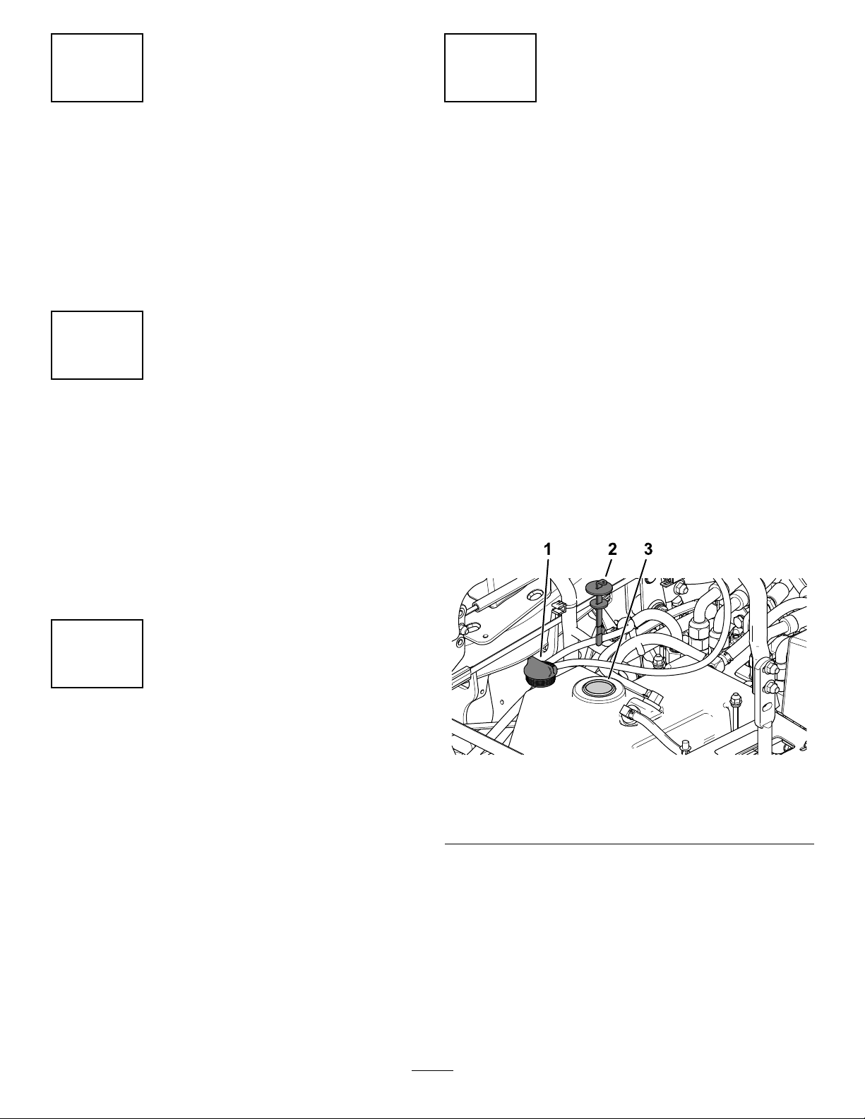
5.Removethehydraulic-tankcap(Figure1).
Beforeyoustarttheengineandusethemachine,
checktheoillevelintheenginecrankcase;referto
theOperator'sManual.
3
CheckingtheTirePressure
NoPartsRequired
Procedure
Frontandreartiresairpressurespecication:124
kPa(18psi).
Note:Checkthetirepressurebeforestartingthe
machine.RefertoyourOperator’sManualforthe
correcttiretype,correctairpressureneeded,and
procedure.
g227849
Figure1
1.Hydraulic-tankcap3.Fillerneck
2.Dipstick
6.Removethedipstickandwipeitwithacleanrag
(Figure1).
7.Placethedipstickintothellerneck,removeit,
andchecktheuidlevel(Figure2).
Note:Ifthelevelisnotwithinthenotchedarea
ofthedipstick,addenoughhigh-qualityhydraulic
uidtoraisetheleveltowithinthenotchedarea.
Important:Donotoverll.
2

Figure2
g228816
1.Fullline2.Addline
8.Replacethedipstickandthreadthellcap
nger-tightontothellerneck.
9.Checkallhosesandttingsforleaks.
5
CheckingtheDeck
Gearbox-FluidLevel
NoPartsRequired
Procedure
1.Parkthemachineonalevelsurface.
2.Lowerthemowerdecktothe25mm(1inch)
heightofcut.
3.Disengagetheblade-controlswitch,movethe
motion-controlleverstotheNEUTRAL-LOCK
position,andengagetheparkingbrake.
4.Shutofftheengineandremovethekey .
g231764
Figure3
1.Dipstick/llplug
7.Iftheuidlevelislow,adduiduntilthelevelis
betweenthemarksonthedipstick.
Important:Donotoverllthegearbox;
overllingthegearboxmaydamageit.
6
CheckingtheWheelLug
NutTorque
NoPartsRequired
Procedure
Beforeyoustarttheengineandusethemachine,
checkthewheellugnuttorque;refertoCheckingthe
WheelLugNutsintheOperator'sManual.
5.Raisethedeck-liftpedaltoexposethetopofthe
mowerdeck.
6.Removethedipstick/llplugfromthetopofthe
gearboxandensurethatthelubricantisbetween
themarksonthedipstick(Figure3).
3

7
InstallingtheBattery
Partsneededforthisprocedure:
2J-bolt
2Wingnut
1Hold-downclamp
Procedure
Important:Thisprocedureonlyappliesto
machinesthatdonotcomewithabattery
installed.
Purchasea12Vbatteryandinstallitintothemachine.
Theenginerequiresaminimumof540A(cold
cranking).
Usethehardwareincludedtoinstallthenewbattery.
RefertoInstallingtheBatteryintheOperator's
Manual.
Figure4
1.Upperpartoftherollbar4.Rotatetheknobout90°
2.Knobinthelatched
position
3.Pulltheknobtounlatch.
4.Pushontherollbarandensurethatbothpins
areengaged(Figure5).
toholditintheunlatched
position.
5.Knobintheunlatched
position
g243267
8
RaisingtheRollover
ProtectionSystem(ROPS)
NoPartsRequired
Procedure
1.Pulltheknobandrotate90°totheunlatched
position(Figure4).
2.Raisetherollbartotheoperateposition,and
rotatetheknobssothattheymovepartiallyinto
thegrooves(Figure4).
3.Raisetherollbartothefulluprightpositionwhile
pushingontheupperrollbarandthepinssnap
intopositionwhentheholesalignwiththepins
(Figure4).
Important:Alwaysusetheseatbeltwiththe
rollbarintheraisedposition.
g008619
Figure5
1.Engagedposition2.Partiallyengaged—do
notoperatethemachine
withtherollbackinthis
position.
4

9
InstallingtheHood-Intake
Kit
Partsneededforthisprocedure:
1Hood-IntakeKit
Procedure
InstalltheHood-IntakeKit;refertotheInstallation
Instructions.
5

10
CheckingtheMachineBeforeDeliverytotheCustomer
(AllMachines)
NoPartsRequired
Procedure
Beforedeliveringthemachinetothecustomer,ensurethatyouperformorhaveperformedtheprocedures
listedinthefollowingtableandinitialeachwhennished.RefertotheOperator'sManualforinstructionson
performingtheseprocedures.
Initial
Checkthetirepressure.
Checkthelevelofthemachine.
Checkthatallspindlesaregreased.
Checktheengine-oillevel.
Checkthehydraulic-uidlevel.
CheckROPSissecure.
Onliquidcooledmachines,checkthelevelofthecoolantintheradiatorandoverowbottle.
Checktheadjustmentoftheparkingbrake.
Ensurethatthemachinetrackscorrectly;refertotheOperator'sManualfortheadjustmentprocedure.
Checkthesafetyinterlocksystem;refertotheOperator'sManual.
EnsurethatthePTOworks.
Checkallfastenersthatyouinstalledtoensurethattheyaretight.
Whenyounishsettingupthemachine,signanddateinthespaceprovidedbelow:
Signature:
CheckProcedure
Date:
6

11
DeliveringtheMachinetotheCustomer
Partsneededforthisprocedure:
1
Operator'sManual
1Engineowner'smanual
1Registrationcard
1
Operatortrainingmaterial
2Key
Procedure
Atdelivery,llinthemodelandserialnumber,completetheitemslistedinthefollowingtable,andinitial
eachwhennished.
ModelNo.
SerialNo.
7

DealerInitial
CustomerInitialCheckProcedure
Showthecustomerwherethefollowingfeaturesarelocatedandhowtheyfunction:
•
Fueltank
•
Oilllcap/Oildipstick
•
Engine-oillter
•
Engine-oildrain
•
Fuelgauge,valveandhose
•
Airlter
•
Radiatorcoolant(ifapplicable)
•
Hydraulic-uidreservoir
•
Hydrauliclter
•
Battery
•
Keyswitch
•
Throttlelever
•
Choke(ifapplicable)
•
Powertakeoffswitch(PTO)
•
Motion-controllevers
•
Parkingbrake
•
Heightofcut
•
Lift-assistlever(ifapplicable)
•
Adjustableseat
•
Hydraulic-bypassvalves
•
RolloverProtectionSystem(ROPS)
•
Deck-owbafe
RefertotheOperator'sManualtopointoutsafetyprocedures,operation,and
maintenanceprocedures.
ReviewthewarrantystatementasshownintheOperator'sManual.
Describethepostsaleserviceproceduresforyourstore.
Assistthecustomerinllingoutandmailingtheregistrationcardorregisteronlineat
www.T oro.com
EnsurethatthecustomerreceivestheOperator'sManual,engineowner’smanual,
SetupInstructions,andoperatortrainingmaterial.
EnsurethatthecustomerknowsthePartsCatalogisavailableatwww.T oro.com.
Assistthecustomerinloadingthemachineusingafull-widthtrailerramp.
Note:Whenyou,thedealerrepresentative,havenisheddeliveringthemachinetothecustomer,signand
dateinthespaceprovidebelowandkeepacopyofthispagefordealerrecords.Also,thedealermustremind
thecustomertouseafull-widthtrailerramptoloadthemachine.
Signature:Date:
Signature:Date:
8
 Loading...