


FormNo.3444-456RevC
ZMaster®Professional7500-DSeriesRidingMower
72028,72029,72065,72074
AufsitzrasenmäherderSerieZMaster®Professional7500-D
72028,72029,72065,72074
TondeuseautoportéeZMaster®Professionalsérie7500-D
72028,72029,72065,72074
ZMaster®7500-Dserieprofessionelezitmaaier
72028,72029,72065,72074
www.T oro.com.
*3444-456*


FormNo.3444-444RevC
ZMaster
®
Professional7500-D
SeriesRidingMower
With60inor72inTURBOFORCE
DischargeMower
ModelNo.72028—SerialNo.408863644andUp
ModelNo.72029—SerialNo.407600000andUp
ModelNo.72065—SerialNo.408864664andUp
ModelNo.72074—SerialNo.408961606andUp
®
Rear
Registeratwww.T oro.com.
OriginalInstructions(EN)
*3444-444*

ItisaviolationofCaliforniaPublicResourceCode
Section4442or4443touseoroperatetheengineon
anyforest-covered,brush-covered,orgrass-covered
landunlesstheengineisequippedwithaspark
arrester,asdenedinSection4442,maintainedin
effectiveworkingorderortheengineisconstructed,
equipped,andmaintainedforthepreventionofre.
Theenclosedengineowner'smanualissupplied
forinformationregardingtheUSEnvironmental
ProtectionAgency(EPA)andtheCaliforniaEmission
ControlRegulationofemissionsystems,maintenance,
andwarranty.Replacementsmaybeorderedthrough
theenginemanufacturer.
GrossorNetTorque:Thegrossornettorque
ofthisenginewaslaboratoryratedbytheengine
manufacturerinaccordancewiththeSocietyof
AutomotiveEngineers(SAE)J1940orJ2723.As
conguredtomeetsafety,emission,andoperating
requirements,theactualenginetorqueonthisclass
ofmowerwillbesignicantlylower.Pleasereferto
theenginemanufacturer’sinformationincludedwith
themachine.
WARNING
CALIFORNIA
Proposition65Warning
Dieselengineexhaustandsomeofits
constituentsareknowntotheStateof
Californiatocausecancer,birthdefects,
andotherreproductiveharm.
Batteryposts,terminals,andrelated
accessoriescontainleadandlead
compounds,chemicalsknownto
theStateofCaliforniatocause
cancerandreproductiveharm.Wash
handsafterhandling.
Introduction
Thisrotary-blade,ridinglawnmowerisintendedtobe
usedbyprofessional,hiredoperators.Itisdesigned
primarilyforcuttinggrassonwell-maintainedlawns
onresidentialorcommercialproperties.Usingthis
productforpurposesotherthanitsintendedusecould
provedangeroustoyouandbystanders.
Readthisinformationcarefullytolearnhowtooperate
andmaintainyourproductproperlyandtoavoid
injuryandproductdamage.Youareresponsiblefor
operatingtheproductproperlyandsafely.
Visitwww.T oro.comforproductsafetyandoperation
trainingmaterials,accessoryinformation,helpnding
adealer,ortoregisteryourproduct.
Wheneveryouneedservice,genuineT oroparts,or
additionalinformation,contactanAuthorizedService
DealerorToroCustomerServiceandhavethemodel
andserialnumbersofyourproductready.Figure1
identiesthelocationofthemodelandserialnumbers
ontheproduct.Writethenumbersinthespace
provided.
Important:Withyourmobiledevice,youcan
scantheQRcode(ifequipped)ontheserial
numberdecaltoaccesswarranty,parts,andother
productinformation.
Useofthisproductmaycauseexposure
tochemicalsknowntotheStateof
Californiatocausecancer,birthdefects,
orotherreproductiveharm.
©2021—TheToro®Company
8111LyndaleAvenueSouth
Bloomington,MN55420
Figure1
1.Modelandserialnumberlocation
ModelNo.
SerialNo.
Thismanualuses2wordstohighlightinformation.
Importantcallsattentiontospecialmechanical
informationandNoteemphasizesgeneralinformation
worthyofspecialattention.
2
g235670
Contactusatwww.Toro.com.
PrintedintheUSA
AllRightsReserved

Thesafety-alertsymbol(Figure2)appearsbothin
thismanualandonthemachinetoidentifyimportant
safetymessagesthatyoumustfollowtoavoid
accidents.Thissymbolwillappearwiththeword
Danger,Warning,orCaution.
•Dangerindicatesanimminentlyhazardous
situationwhich,ifnotavoided,willresultindeath
orseriousinjury.
•Warningindicatesapotentiallyhazardous
situationwhich,ifnotavoided,couldresultin
deathorseriousinjury.
•Cautionindicatesapotentiallyhazardoussituation
which,ifnotavoided,mayresultinminoror
moderateinjury.
Figure2
Safety-alertsymbol
Contents
Safety.......................................................................5
GeneralSafety...................................................5
SlopeIndicator...................................................6
SafetyandInstructionalDecals..........................7
ProductOverview...................................................13
Controls...........................................................14
HorizonDisplayMonitor................................14
Specications..................................................16
Attachments/Accessories.................................16
BeforeOperation.................................................17
BeforeOperationSafety...................................17
AddingFuel......................................................18
PerformingDailyMaintenance..........................19
BreakinginaNewMachine..............................19
UsingtheRolloverProtectionSystem
(ROPS).........................................................19
sa-black
UsingtheSafety-InterlockSystem....................20
PositioningtheSeat..........................................21
UnlatchingtheSeat..........................................21
ChangingtheSeatSuspension.........................21
DuringOperation.................................................21
DuringOperationSafety...................................21
OperatingtheParkingBrake.............................24
OperatingtheMowerBlade-ControlSwitch
(PTO)............................................................24
StartingtheEngine...........................................25
ShuttingOfftheEngine.....................................25
UsingtheMotion-ControlLevers.......................26
DrivingtheMachine..........................................26
AdjustingtheHeightofCut...............................27
AdjustingtheAnti-ScalpRollers........................28
AdjustingtheSkids...........................................29
OperatingwiththeOverheatSensor.................29
OperatingTips.................................................30
AfterOperation....................................................31
AfterOperationSafety......................................31
UsingtheDrive-WheelReleaseValves.............31
TransportingtheMachine.................................31
Maintenance...........................................................33
MaintenanceSafety..........................................33
RecommendedMaintenanceSchedule(s)...........33
Lubrication..........................................................35
GreasingtheMachine.......................................35
LubricatingtheDriveU-JointsandSplined
SlipJoint.......................................................35
GreasingtheCasterPivots...............................36
GreasingtheCaster-WheelHubs.....................36
EngineMaintenance...........................................37
EngineSafety...................................................37
ServicingtheAirCleaner..................................37
ServicingtheEngineOil....................................38
InspectingtheEngine-ValveClearance............39
FuelSystemMaintenance...................................40
DrainingtheFuelFilter/WaterSeparator...........40
ReplacingtheWaterSeparator........................40
3

CheckingtheFuelLinesand
Connections..................................................40
ElectricalSystemMaintenance...........................41
ElectricalSystemSafety...................................41
ServicingtheBattery.........................................41
ServicingtheFuses..........................................42
DriveSystemMaintenance..................................43
CheckingtheSeatBelt.....................................43
AdjustingtheTracking......................................43
CheckingtheTirePressure...............................44
CheckingtheWheelLugNuts...........................44
AdjustingtheCaster-PivotBearing...................44
ServicingtheGearbox......................................45
CoolingSystemMaintenance..............................46
CoolingSystemSafety.....................................46
CheckingtheEngine-CoolantLevel..................46
CleaningtheRadiator.......................................46
ChangingtheEngineCoolant...........................47
BrakeMaintenance.............................................48
AdjustingtheParkingBrake..............................48
BeltMaintenance................................................49
InspectingtheBelts..........................................49
ReplacingtheMowerBelt.................................49
CheckingtheAlternator-BeltT ension................50
ControlsSystemMaintenance.............................51
AdjustingtheControl-HandlePosition..............51
AdjustingtheMotion-ControlLinkage...............51
AdjustingtheMotion-ControlDamper...............52
HydraulicSystemMaintenance...........................53
HydraulicSystemSafety...................................53
ServicingtheHydraulicSystem........................53
MowerDeckMaintenance....................................55
BladeSafety.....................................................55
ServicingtheCuttingBlades.............................55
LevelingtheMowerDeck..................................58
Cleaning..............................................................61
CleaningtheEngineandExhaustSystem
Area..............................................................61
CleaningtheMachineandMower
Deck..............................................................61
DisposingofWaste...........................................61
Storage...................................................................62
StorageSafety..................................................62
CleaningandStorage.......................................62
Troubleshooting......................................................63
Schematics.............................................................65
4

Safety
Thismachinehasbeendesignedinaccordancewith
ENISO5395.
GeneralSafety
Thisproductiscapableofamputatinghandsand
feetandofthrowingobjects.Alwaysfollowallsafety
instructionstoavoidseriouspersonalinjuryordeath.
•Readandunderstandthecontentsofthis
Operator’sManualbeforestartingtheengine.
•Keepbystandersandchildrenaway .
•Donotallowchildrenoruntrainedpeopleto
operateorservicethemachine.Allowonlypeople
whoareresponsible,trained,familiarwiththe
instructions,andphysicallycapabletooperateor
servicethemachine.
•Alwayskeeptherollbarinthefullyraisedand
lockedpositionandusetheseatbelt.
•Donotoperatethemachineneardrop-offs,
ditches,embankments,water,orotherhazards,or
onslopesgreaterthan15°.
•Donotputyourhandsorfeetnearmoving
componentsofthemachine.
•Donotoperatethemachinewithoutallguards,
safetyswitches,andothersafetyprotective
devicesinplaceandfunctioningproperly.
•Shutofftheengine,removethekey ,andwait
forallmovingpartstostopbeforeleavingthe
operator’sposition.Allowthemachinetocool
beforeservicing,adjusting,fueling,cleaning,or
storingit.
5
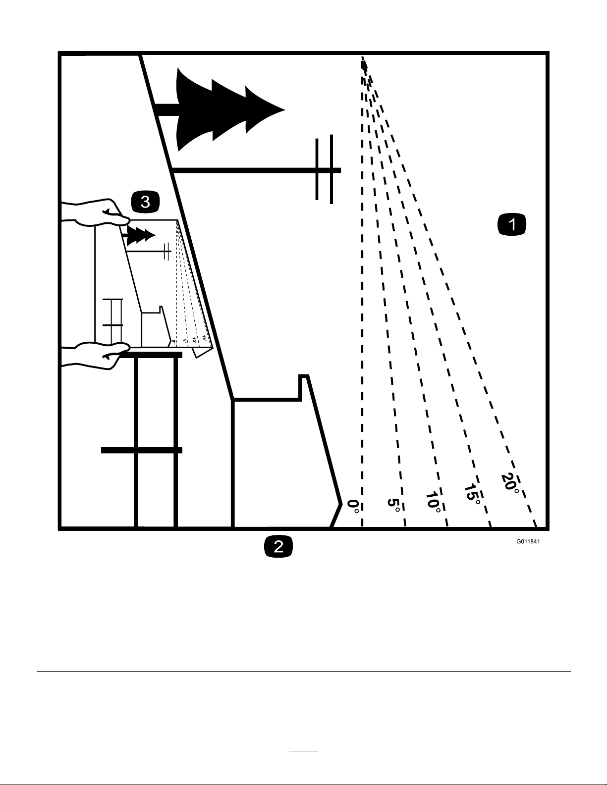
SlopeIndicator
Figure3
Youmaycopythispageforpersonaluse.
1.Themaximumslopeyoucanoperatethemachineonis15degrees.Usetheslopecharttodeterminethedegreeofslopeof
hillsbeforeoperating.Donotoperatethismachineonaslopegreaterthan15degrees.Foldalongtheappropriateline
tomatchtherecommendedslope.
2.Alignthisedgewithaverticalsurface,atree,building,fencepole,etc.
3.Exampleofhowtocompareslopewithfoldededge
6
g011841

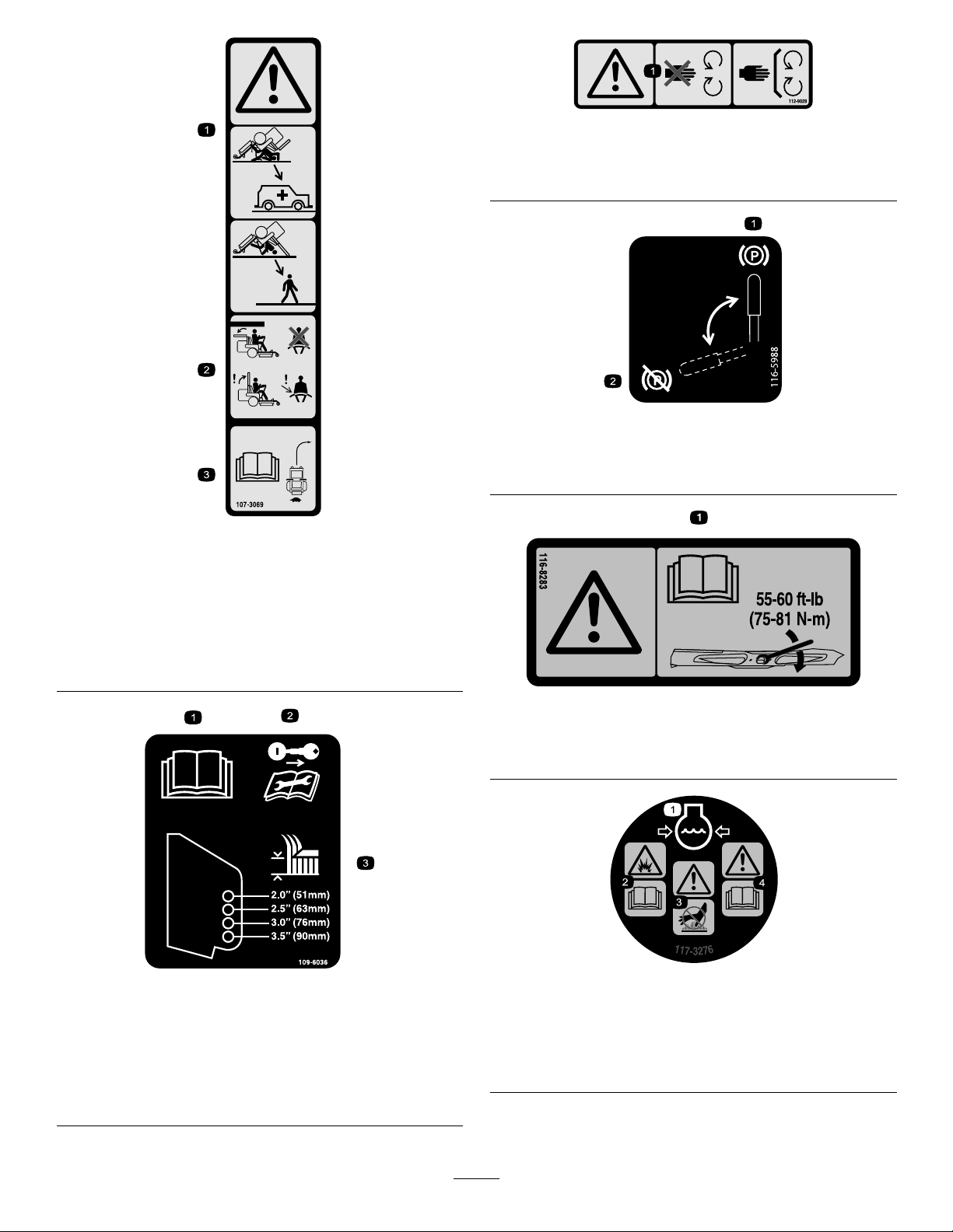
SafetyandInstructionalDecals
Safetydecalsandinstructionsareeasilyvisibletotheoperatorandarelocatednearanyarea
ofpotentialdanger.Replaceanydecalthatisdamagedormissing.
BatterySymbols
Someorallofthesesymbolsareonyourbattery.
decalbatterysymbols
1.Explosionhazard6.Keepbystandersaway
fromthebattery.
2.Nore,opename,or
smoking
7.Weareyeprotection;
explosivegasescan
causeblindnessandother
injuries.
3.Causticliquid/chemical
burnhazard
8.Batteryacidcancause
blindnessorsevereburns.
4.Weareyeprotection.9.Flusheyesimmediately
withwaterandgetmedical
helpfast.
5.ReadtheOperator's
Manual.
10.Containslead;donot
discard
Manufacturer'sMark
1.Indicatesthebladeisidentiedasapartfromtheoriginal
machinemanufacturer.
decal99-8936
99-8936
1.Machinespeed4.Neutral
2.Fast5.Reverse
3.Slow
decal106-5517
106-5517
decaloemmarkt
1.Warning—donottouchthehotsurface.
1.Grease
1.Donotstephere.
decal58-6520
58-6520
decal93-6687
93-6687
7
112-9028
1.Warning—stayawayfrommovingparts;keepallguards
andshieldsinplace.
116-5988
decal112-9028
decal116-5988
decal107-3069
107-3069
1.Warning–thereisnorolloverprotectionwhentherollbaris
down.
2.Toavoidinjuryordeathfromarolloveraccident,keepthe
rollbarintheraisedandlockedpositionandweartheseat
belt.Lowertherollbaronlywhenabsolutelynecessary;do
notweartheseatbeltwhentherollbarisdown.
3.ReadtheOperator'sManual;driveslowlyandcarefully.
1.Parkingbrake—engaged2.Parking
brake—disengaged
decal116-8283
116-8283
1.Warning—readtheOperator'sManualforinstructionson
torquingthebladebolt/nutto75to81N∙m(55to60ft-lb).
109-6036
RearDischargeMachinesOnly
1.ReadtheOperator’sManual.
2.Removethekeyandreadtheinstructionsbeforeservicing
orperformingmaintenance.
3.Heightofcut
decal109-6036
1.Enginecoolantunder
pressure
2.Explosionhazard—read
theOperator'sManual.
117-3276
3.Warning—donottouchthe
hotsurface.
4.Warning—readthe
Operator'sManual.
decal117-3276
8
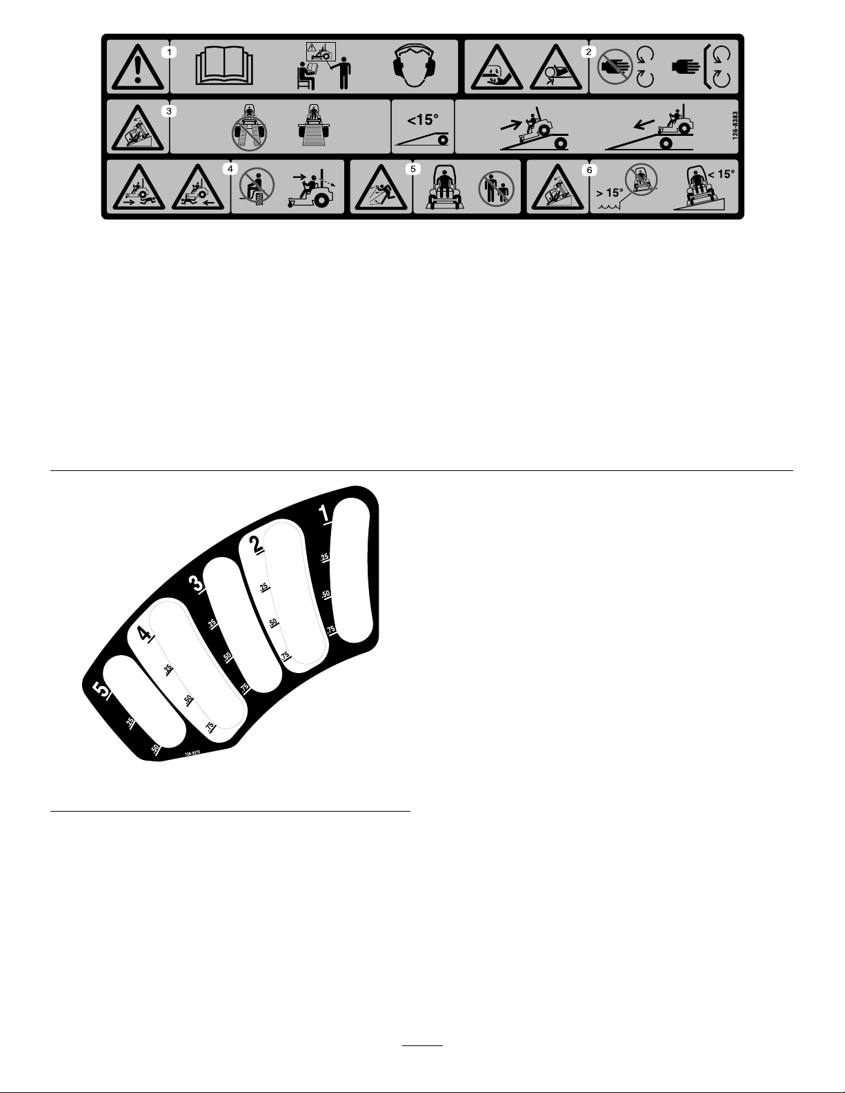
126-8383
Note:Thismachinecomplieswiththeindustrystandardstabilitytestinthestaticlateralandlongitudinaltestswiththemaximum
recommendedslopeindicatedonthedecal.ReviewtheinstructionsforoperatingthemachineonslopesintheOperator’sManualas
wellastheconditionsinwhichyouwouldoperatethemachinetodeterminewhetheryoucanoperatethemachineintheconditionson
thatdayandatthatsite.Changesintheterraincanresultinachangeinslopeoperationforthemachine.
decal126-8383
1.Warning—readtheOperator’sManual;donotoperatethis
machineunlessyouaretrained;wearhearingprotection.
2.Cutting/dismembermenthazardofthehand,mowerblade;
entanglementhazardofthehand,belt—stayawayfrom
movingparts;keepallguardsandshieldsinplace.
3.Ramphazard—donotusedualrampswhenloadingontoa
trailer;use1rampwideenoughforthemachine;usearamp
withaslopelessthan15°;backuptherampwhenloadingthe
machineanddriveforwardofftherampwhenunloading.
4.Runover/backoverhazard—donotcarrypassengers;look
behindyouwhenmowinginreverse.
5.Thrownobjecthazard—keepbystandersaway .
6.Tippinghazard—donotusethemachineneardrop-offsor
onslopesgreaterthan15°;onlyoperateacrossslopesless
than15°.
decal126-9275
126-9275
9
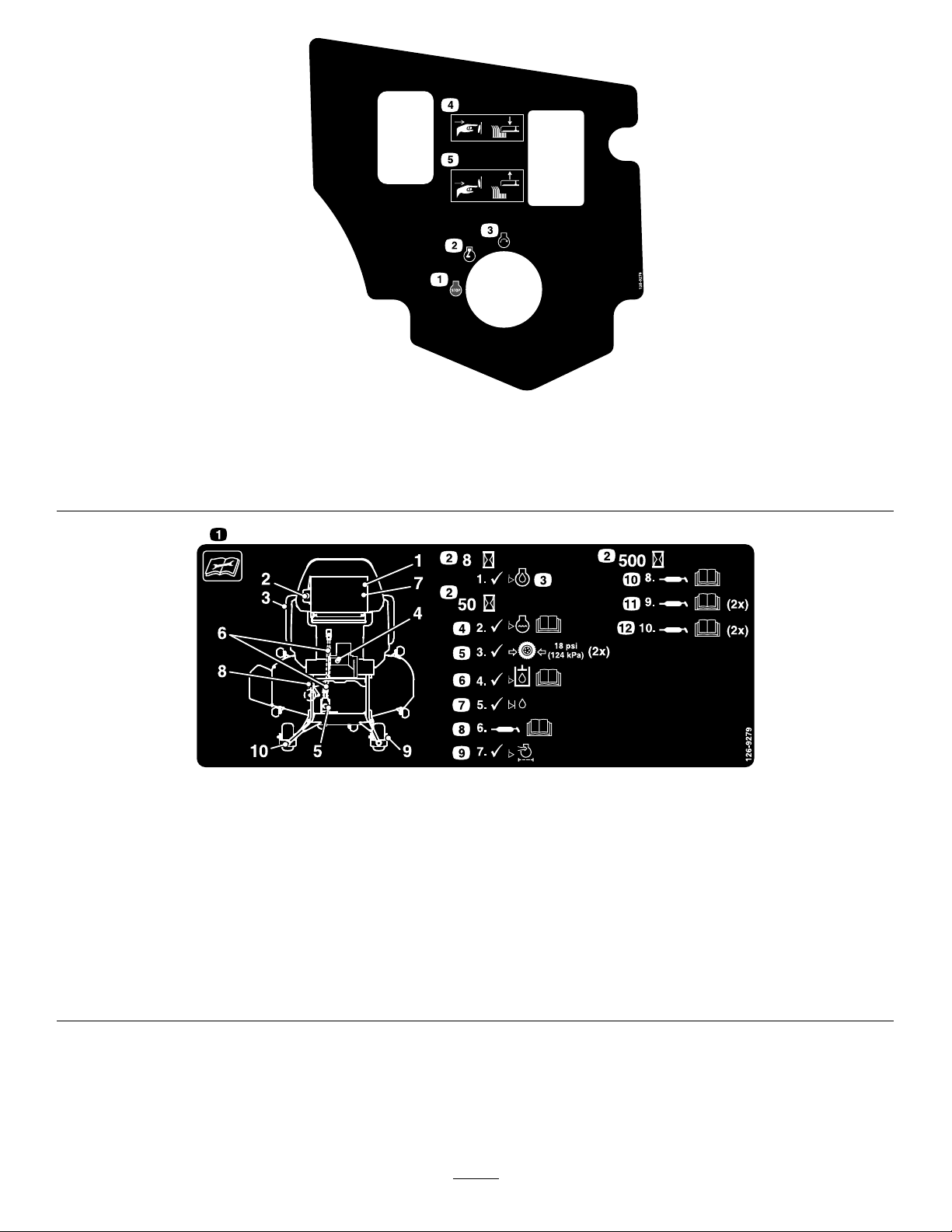
126-9278
1.Engine—Off4.Pushthebottomofthebuttontolowerthedeck.
2.Engine—On5.Pushthetopofthebuttontoraisethedeck.
3.Engine—Start
126-9279
decal126-9278
decal126-9279
1.Readtheinstructionsbeforeservicingorperforming
7.Checkthejackshaft-uidlevel.
maintenancetothemachine.
2.Timeinterval
8.Greasethedeck-drivePTO;refertotheOperator'sManual
forfurtherinstructions.
3.Checktheengine-oillevel.9.Checktheaircleaner .
4.Checkthecoolantlevel;refertotheOperator'sManualfor
furtherinstructions.
10.Greasetheidlerpivot;refertotheOperator'sManualfor
furtherinstructions
5.Checkthetirepressure(2locations).11.Greasethefrontcasterwheelbearings(2locations);referto
theOperator'sManualforfurtherinstructions.
6.Checkhydraulic-uidlevel;refertotheOperator'sManual
forfurtherinstructions.
12.Greasethefrontcasterpivots(2locations);refertothe
Operator'sManualforfurtherinstructions.
10
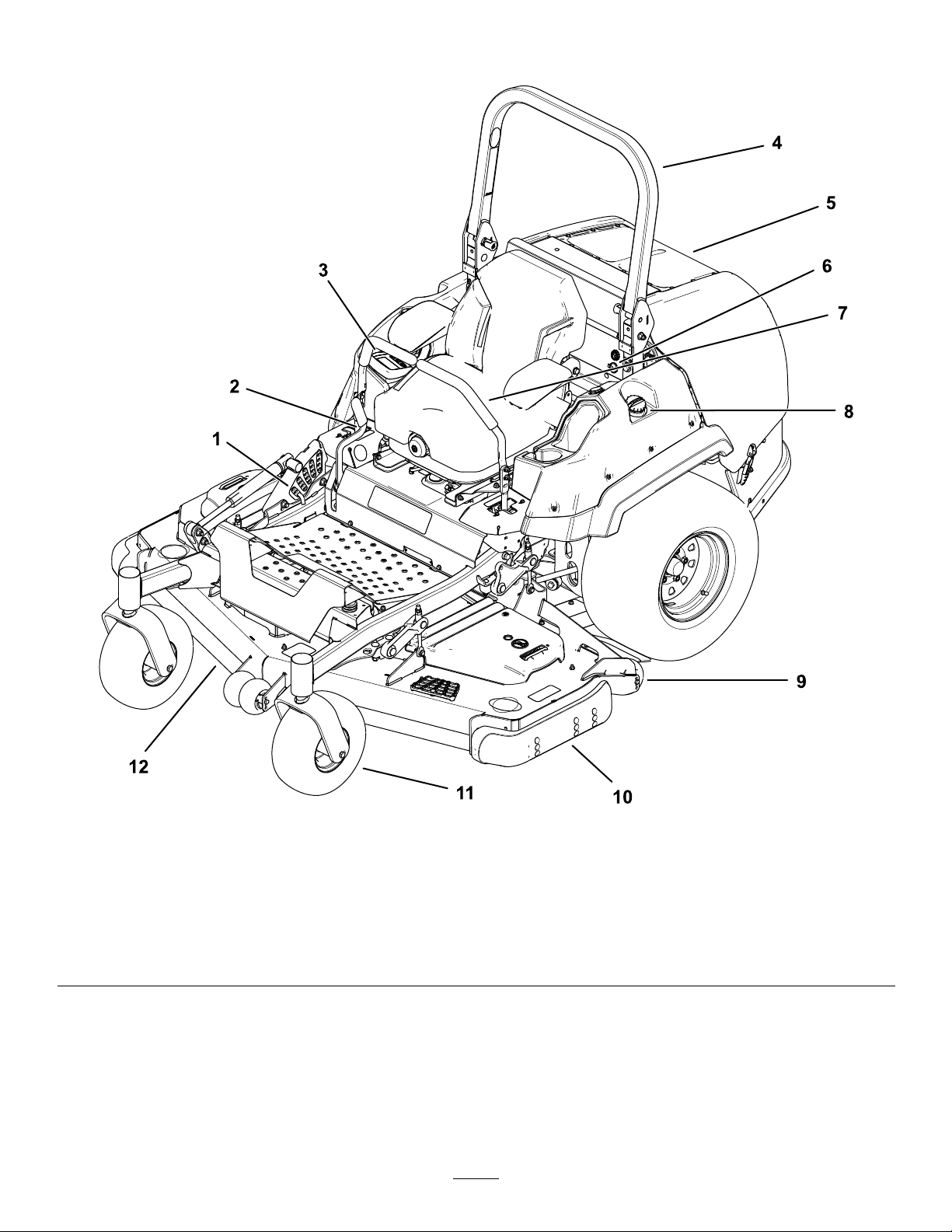
decal135-0328
135-0328
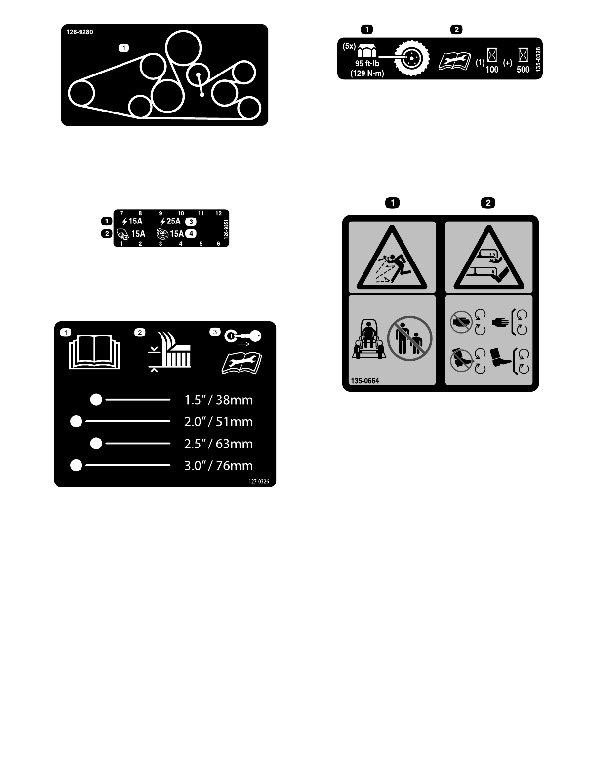
126-9280
ForModelswith152cm(60-inch)or183cm(72-inch)
DeckswithRearDischarge
1.Beltrouting
126-9351
1.Chassis(15A)3.Main(25A)
2.Accessory(15A)4.Powerpoint(15A)
1.Torquethewheellugnuts
decal126-9280
to129N∙m(95ft-lb).
2.Readandunderstand
theOperator'sManual
beforeperformingany
maintenance;checkthe
torqueaftertherst100
hours,thenevery500
hours,thereafter.
decal126-9351
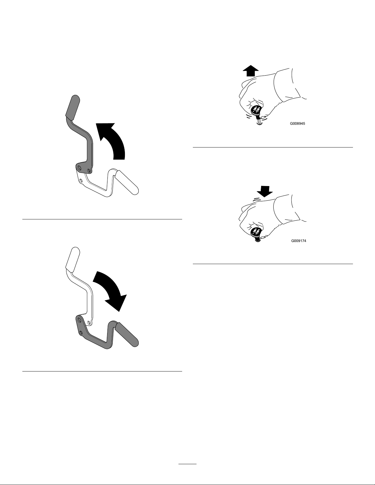
decal135-0664
135-0664
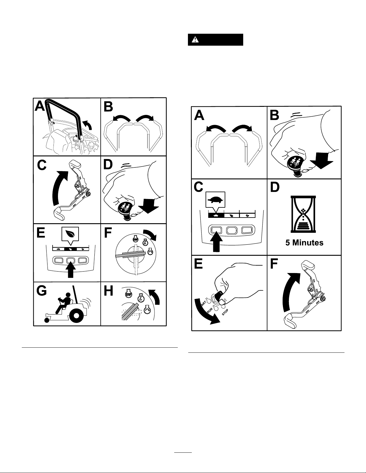
1.ReadtheOperator's
Manual.
2.Heightofcut
127-0326
3.Removethekeyand
readtheOperator's
Manualbeforeperforming
maintenance.
1.Thrownobject
hazard—keepbystanders
away.
2.Cutting/dismemberment
hazardofhandsand
feet—stayawayfrom
movingparts;keepall
guardsandshieldsin
place.
decal127-0326
11

135-0679
1.Rotatingdrivelinehazard/entanglementhazard;belt—stay
awayfrommovingparts;keepallguardsandshieldsin
place.
decal133-8062
133-8062
decal135-0679
135-1432
135-2837
1.ReadtheOperator’sManualformoreinformation;Use
redT orowet-clutchtransmissionuid;donotusegreen
hydraulicuid.
decal135-1432
decal135-2837
12
ProductOverview
Figure4
1.Height-of-cutpin
2.Parking-brakelever8.Fuel-tankcap
3.Monitor/controls
4.Rollbar
5.Enginescreen
6.Audiblealarmandpowerpoint12.Mowerdeck
7.Motion-controllever
9.Anti-scalproller
10.Skid
11.Casterwheel
13
g227303

Controls
Becomefamiliarwithallthecontrolsbeforeyoustart
theengineandoperatethemachine.
ControlPanel
Figure5
g228164
g225792
HorizonDisplayMonitor
Figure6
1.Horizondisplaymonitor3.Keyswitch
2.Deck-liftswitch
4.Blade-controlswitch
(powertakeoff)
HorizonDisplayMonitor
RefertotheSoftwareGuidefordetailedinformation
explainingtheoperatorinterfacethatallowsyouto
accessinformation,resetcounters,modifysystem
settings,andtroubleshoottheequipment.
1.Screen
2.LEDstatuslight
InformationScreen
3.Buttons
Theinformationscreendisplaysinformationrelative
tomachineoperation;refertotheSoftwareGuidefor
moreinformation.
Buttons
Themulti-functionalbuttonsarelocatedatthebottom
ofthepanel.Theiconsdisplayedontheinformation
screenabovethebuttonsindicatethecurrentfunction.
Thebuttonsallowyoutoselecttheenginespeedand
navigatethroughsystemmenus.
RefertotheSoftwareGuideformoreinformation.
LEDStatusLight
TheLEDstatuslightismulti-coloredtoindicatethe
systemstatusandislocatedontherightsideofthe
panel.Duringstartup,theLEDilluminatesredto
orangetogreentoverifyfunctionality.
•Solidgreen—indicatesnormaloperatingactivity
•Blinkingred—indicatesanactivefault
•Blinkinggreenandorange—indicatesthata
clutchresetisrequired
RefertotheSoftwareGuideformoreinformation.
Alarm
Ifanerroroccurs,anerrormessagedisplays,theLED
turnsred,andthealarmsoundsaudiblyasfollows:
14

•Afastchirpsoundindicatescriticalerrors.
•Aslowchirpingsoundindicateslesscriticalerrors,
suchasrequiredmaintenanceorserviceintervals.
Note:Duringstartup,thealarmsoundsbrieyto
verifyfunctionality .
RefertotheSoftwareGuideformoreinformation.
Blade-ControlSwitch(Power
Takeoff)
Theblade-controlswitch(PTO)engagesand
disengagespowertothemowerblades(Figure5).
TheLCDindicatorappearsontheinformationscreen
whenthePTOswitchisdisengaged.
HourMeter
Thehourmeterrecordsthenumberofhoursthe
enginehasoperated.Itoperateswhentheengine
isrunning.Usethesetimesforschedulingregular
maintenance(Figure5).
HoursaredisplayedinEngine-Offscreenorinthe
EngineHourCountermenu.
RefertotheSoftwareGuideformoreinformation.
KeySwitch
Usethisswitchtostarttheengine.Ithas3positions:
START,RUN,andOFF.
Note:TheLCDindicatorsappearwheneachcontrol
meetsthe“safetostart”mode(e.g.,theindicator
turnsonwhenyouareintheseat.)
Note:TheengineECUcontrolstheglowplugsduring
coldstarts.Ifthecoolanttemperatureistoolow,the
glowsymboldisplaysonthemonitorandthestarter
doesnotcrankwhenyouturntheenginetotheSTART
position.TheglowplugsactivateintheONorSTART
position.Oncetheglowhasbeenonlongenough
forthecurrenttemperature,theglowsymbolonthe
monitordisappearsandtheenginecrankswhen
turnedtotheSTARTposition.
Note:Thesystemallowsyoutostartthemachinethe
withthePTOswitchengaged,butdoesnotengage
theblades.YoumustresetthePTOtoengagethe
PTO.
ThrottleControl
Note:MachinesequippedwiththeHorizonDisplay
Monitorhaveaclutchsaver,whichallowsthethrottle
toautomaticallyreducetheenginespeedwhen
youdisengagethePTOswitch.Engagingand
disengagingthePTOswitchchangestheengine
throttlebetweenMOWandTRANSPORTmode.
Note:Thesystemallowsyoutostartthemachine
withthePTOswitchengaged,butdoesnotengage
theblades.EngagingthePTOrequiresyoutoreset
thePTOswitchbydisengaging,thenengagingit.
Deck-LiftSwitch
Presstheswitchrearwardtoraisethedeck.
Presstheswitchforwardtolowerthedeck.
Motion-ControlLevers
Usethemotion-controlleverstodrivethemachine
forward,reverse,andturneitherdirection(Figure4).
Neutral-LockPosition
Movethemotion-controlleversoutwardfromthe
centertotheNEUTRAL-LOCKpositionwhenexiting
themachine(Figure22).Alwayspositionthe
motion-controlleversintotheNEUTRAL-LOCKposition
whenyoustopthemachineorleaveitunattended.
Parking-BrakeLever
Wheneveryoushutofftheengine,engagetheparking
braketopreventaccidentalmovementofthemachine.
Thethrottlecontrolstheenginespeed,andthereare
3speeds:Maximum,Efcient,andLow.
RefertotheSoftwareGuideformoreinformation.
15

Specications
Attachments/Accessories
OverallWidth
60-inchDeck72-inchDeck
168.2cm(66.2inches)198.7cm(78-3/16inches)
OverallLength
Rollbarupordown
255.5cm(100-5/8inches)
OverallHeight
Rollbarup
Rollbardown
182.4cm(71-13/16inches)
129.5cm(51inches)
OverallHeight
Rollbarup
Rollbardown
182.4cm(71-13/16inches)
129.5cm(51inches)
TreadWidthofDriveWheels
112cm(44-1/8inches)
TreadWidthofCasterWheels
(Center-to-CenterofTires)
AselectionofT oroapprovedattachmentsand
accessoriesisavailableforusewiththemachine
toenhanceandexpanditscapabilities.Contact
yourAuthorizedServiceDealerorauthorizedT oro
distributororgotowww.Toro.comforalistofall
approvedattachmentsandaccessories.
Toensureoptimumperformanceandcontinuedsafety
certicationofthemachine,useonlygenuineT oro
replacementpartsandaccessories.Replacement
partsandaccessoriesmadebyothermanufacturers
couldbedangerous,andsuchusecouldvoidthe
productwarranty.
60-inchDeck72-inchDeck
84cm(33-1/8inches)84cm(33-1/8inches)
WheelBase(CenterofCasterTiretoCenter
ofDriveTire)
60-inchDeck72-inchDeck
157.2cm(61-7/8inches)157.2cm(61-7/8inches)
16

Operation
Note:Determinetheleftandrightsidesofthe
machinefromthenormaloperatingposition.
BeforeOperation
BeforeOperationSafety
GeneralSafety
•Donotallowchildrenoruntrainedpeopleto
operateorservicethemachine.Localregulations
mayrestricttheageoftheoperator.Theowner
isresponsiblefortrainingalloperatorsand
mechanics.
•Inspecttheareawhereyouwillusethemachine,
andremoveallobjectsthatcouldinterferewith
theoperationofthemachineorthatthemachine
couldthrow.
•Becomefamiliarwiththesafeoperationofthe
equipment,operatorcontrols,andsafetysigns.
•Checkthatoperator-presencecontrols,safety
switches,andguardsareattachedandworking
properly.Donotoperatethemachineunlessthey
arefunctioningproperly.
•Shutofftheengine,removethekey ,andwait
forallmovingpartstostopbeforeleavingthe
operator’sposition.Allowthemachinetocool
beforeservicing,adjusting,fueling,cleaning,or
storingit.
•Beforemowing,inspectthemachinetoensure
thatthecuttingassembliesareworkingproperly.
•Evaluatetheterraintodeterminetheappropriate
equipmentandanyattachmentsoraccessories
requiredtooperatethemachineproperlyand
safely.
•Wearappropriateclothing,includingeye
protection;longpants;substantial,slip-resistant
footwear;andhearingprotection.Tiebacklong
hairanddonotwearlooseclothingorloose
jewelry.
•Donotcarrypassengersonthemachine.
•Keepbystandersandpetsawayfromthemachine
duringoperation.Shutoffthemachineand
attachment(s)ifanyoneentersthearea.
•Donotoperatethemachineunlessallguards
andsafetydevices,suchasthedeectors,arein
placeandfunctioningproperly.Replacewornor
deterioratedpartswhennecessary.
FuelSafety
•Fuelisextremelyammableandhighlyexplosive.
Areorexplosionfromfuelcanburnyouand
othersandcandamageproperty.
–Topreventastaticchargefromignitingthefuel,
placethecontainerand/ormachinedirectlyon
thegroundbeforelling,notinavehicleoron
anobject.
–Fillthefueltankoutdoorsonlevelground,in
anopenarea,andwhentheengineiscold.
Wipeupanyfuelthatspills.
–Donothandlefuelwhensmokingoraroundan
openameorsparks.
–Donotremovethefuelcaporaddfueltothe
tankwhiletheengineisrunningorhot.
–Ifyouspillfuel,donotattempttostartthe
engine.Avoidcreatingasourceofignitionuntil
thefuelvaporshavedissipated.
–Storefuelinanapprovedcontainerandkeep
itoutofthereachofchildren.
•Fuelisharmfulorfatalifswallowed.Long-term
exposuretovaporscancauseseriousinjuryand
illness.
–Avoidprolongedbreathingofvapors.
–Keepyourhandsandfaceawayfromthe
nozzleandthefuel-tankopening.
–Keepfuelawayfromyoureyesandskin.
•Donotstorethemachineorfuelcontainerwhere
thereisanopename,spark,orpilotlight,such
asonawaterheateroronotherappliances.
•Donotllcontainersinsideavehicleoronatruck
ortrailerbedwithaplasticliner.Alwaysplace
containersonthegroundandawayfromyour
vehiclebeforelling.
•Removetheequipmentfromthetruckortrailer
andrefuelitwhileitisontheground.Ifthisisnot
possible,thenrefuelfromaportablecontainer
ratherthanfromafuel-dispensernozzle.
•Donotoperatethemachinewithouttheentire
exhaustsysteminplaceandinproperworking
condition.
•Keepthefuel-dispensernozzleincontactwith
therimofthefueltankorcontaineropeningat
alltimesuntilfuelingiscomplete.Donotusea
nozzlelock-opendevice.
•Ifyouspillfuelonyourclothing,changeyour
clothingimmediately .
•Donotoverllthefueltank.Replacethefuelcap
andtightenitsecurely.
•Cleangrassanddebrisfromthecuttingunit,
mufer,drives,andenginecompartmenttohelp
preventres.Cleanupoilorfuelspills.
17

AddingFuel
5.Fillthefueltanktothebottomofthellerneck
(Figure7).
RecommendedFuel
Theenginerunsonclean,freshdieselfuelwith
aminimumcetaneratingof40.Purchasefuelin
quantitiesthatcanbeusedwithin30daystoensure
fuelfreshness.
Usesummer-gradedieselfuel(No.2-D)at
temperaturesabove-7°C(20°F)andwinter-grade
dieselfuel(No.1-DorNo.1-D/2-Dblend)below
-7°C(20°F).Useofwinter-gradedieselfuelatlower
temperaturesprovideslowerashpointandpour
pointcharacteristics,thereforeeasingstartabilityand
lesseningchancesofchemicalseparationofthefuel
duetolowertemperatures(waxappearance,which
maypluglters).
Usingsummer-gradedieselfuelabove-7°C
(20°F)contributestowardlongerlifeofthepump
components.
Important:Donotusekeroseneorgasoline
insteadofdieselfuel.Failuretoobservethis
cautionwilldamagetheengine.
Note:Donotllthefueltankcompletelyfull.
Theemptyspaceinthetankallowsthefuelto
expand.
BiodieselReady
Thismachinecanalsouseabiodieselblendedfuel
ofuptoB20(20%biodiesel,80%petrodiesel).The
petrodieselportionshouldbeultralowsulfur.
Observethefollowingprecautions:
•Thebiodieselportionofthefuelmeetspecication
ASTMD6751orEN14214.
•TheblendedfuelcompositionshouldmeetASTM
D975orEN590.
•Paintedsurfacesmaybedamagedbybiodiesel
blends.
•UseB5(biodieselcontentof5%)orlesserblend
incoldweather.
•Monitorseals,hoses,gasketsincontactwithfuel
astheymaydegradeovertime.
•Fuellterpluggingmaybeexpectedforatime
afterconvertingtobiodieselblends.
•Contactyourdistributorformoreinformationon
biodiesel.
g027726
Figure7
FillingtheFuelTank
1.Parkthemachineonalevelsurface.
2.Engagetheparkingbrake.
3.Shutofftheengineandremovethekey .
4.Cleanaroundthefuel-tankcap.
18

PerformingDaily
Maintenance
Beforestartingthemachineeachday,performthe
EachUse/DailyprocedureslistedinMaintenance
(page33).
BreakinginaNewMachine
Newenginestaketimetodevelopfullpower.Mower
decksanddrivesystemshavehigherfrictionwhen
new,placingadditionalloadontheengine.Allow
40to50hoursofbreak-intimefornewmachinesto
developfullpowerandbestperformance.
UsingtheRollover
ProtectionSystem(ROPS)
3.Lowertherollbartothedownposition(Figure
8).
g225804
Figure8
WARNING
Toavoidinjuryordeathfromrollover,keep
therollbarinthefullyraised,lockedposition
andusetheseatbelt.
Ensurethattheseatissecuredtothe
machine.
WARNING
Thereisnorolloverprotectionwhentheroll
barisinthedownposition.
•Lowertherollbaronlywhenabsolutely
necessary.
•Donotweartheseatbeltwhentherollbar
isinthedownposition.
•Driveslowlyandcarefully.
•Raisetherollbarassoonasclearance
permits.
•Checkcarefullyforoverheadclearances
(i.e.,branches,doorways,electricalwires)
beforedrivingunderanyobjectsanddo
notcontactthem.
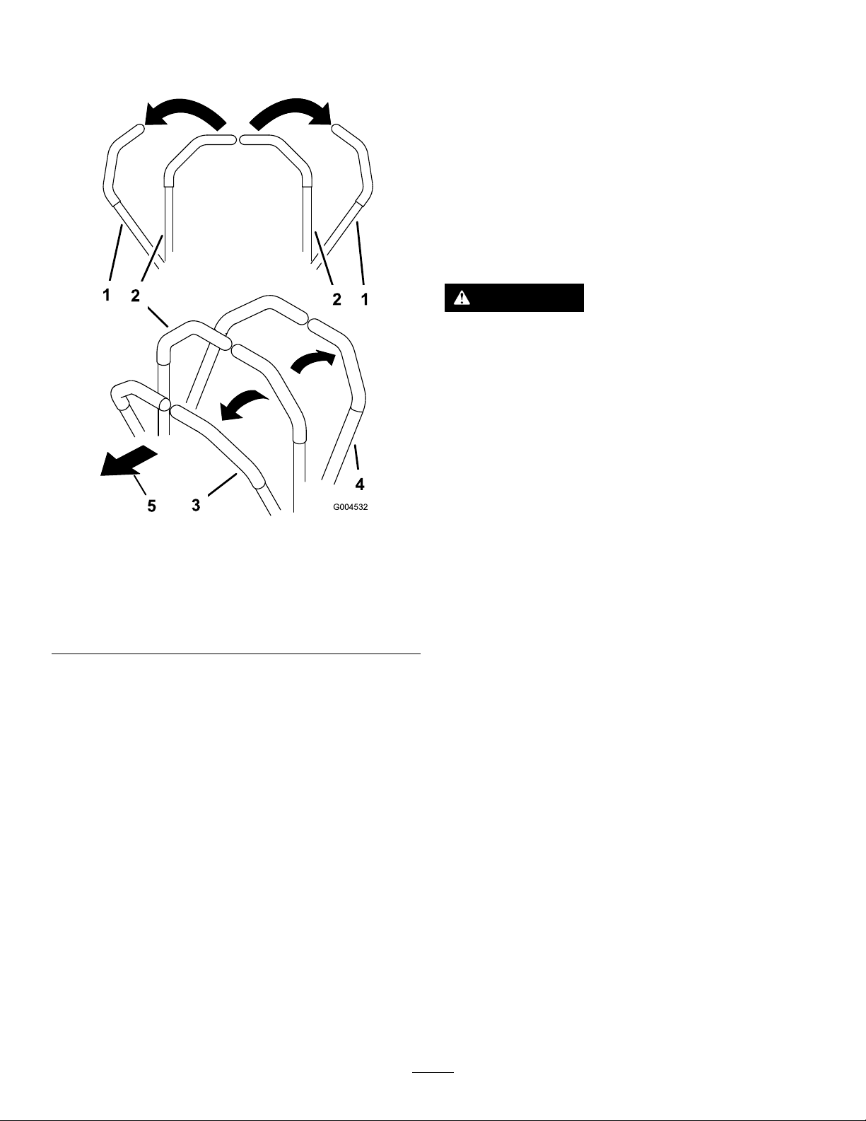
1.Upperpartoftherollbar4.Rotatetheknobout90°
2.Knobinthelatched
position
3.Pulltheknobtounlatch.
toholditintheunlatched
position.
5.Knobintheunlatched
position
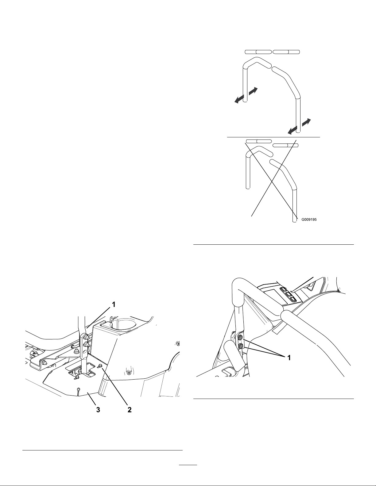
RaisingtheRollBar
Important:Alwaysusetheseatbeltwiththeroll
barintheraisedposition.
1.Raisetherollbartotheoperatingpositionand
rotatetheknobsuntiltheymovepartiallyinto
thegrooves(Figure9).
2.Raisetherollbartothefulluprightpositionwhile
pushingontheupperrollbarsothatthepins
snapintopositionwhentheholesalignwiththe
pins(Figure9).
3.Pushontherollbarandensurethatbothpins
areengaged(Figure9).
LoweringtheRollBar
Important:Lowertherollbaronlywhen
absolutelynecessary .
1.Tolowertherollbar,applyforwardpressureto
theupperpartoftherollbar.
2.Pullbothknobsoutandrotatethem90degrees
sotheyarenotengaged(Figure8).
19

Figure9
1.Engaged2.Partiallyengaged—donot
operatethemachinewith
theROPSinthisposition.
UsingtheSafety-Interlock
System
WARNING
Ifthesafety-interlockswitchesare
disconnectedordamaged,themachinecould
operateunexpectedly,causingpersonal
injury.
•Donottamperwiththeinterlockswitches.
•Checktheoperationoftheinterlock
switchesdailyandreplaceanydamaged
switchesbeforeoperatingthemachine.
Understandingthe
Safety-InterlockSystem
Thesafety-interlocksystemisdesignedtopreventthe
enginefromstartingunless:
•Theparkingbrakeisengaged.
•Theblade-controlswitch(PTO)isdisengaged.
•Themotion-controlleversareintheNEUTRAL-LOCK
position.
Thesafety-interlocksystemalsoisdesignedtoshut
offtheenginewhenthemotion-controlleversare
movedfromtheNEUTRAL-LOCKpositionwiththe
parkingbrakeengagedorifyourisefromtheseat
whenthePTOisengaged.
TheHorizonDisplayMonitorhasindicatorstonotify
theuserwhentheinterlockcomponentisinthe
correctposition.Whenthecomponentisinthecorrect
position,anindicatordisplaysonthescreen.
g230650
Figure10
1.Indicatorsdisplaywhentheinterlockcomponentsareinthe
correctposition
g008619
TestingtheSafety-Interlock
System
ServiceInterval:Beforeeachuseordaily
Testthesafety-interlocksystembeforeyouusethe
machineeachtime.Ifthesafetysystemdoesnot
operateasdescribedbelow,haveanAuthorized
ServiceDealerrepairthesafetysystemimmediately.
1.Sitontheseat,engagetheparkingbrake,and
movetheblade-controlswitch(PTO)totheON
position.Trystartingtheengine;theengine
shouldnotstart.
2.Sitontheseat,engagetheparkingbrake,and
movetheblade-controlswitch(PTO)totheOFF
position.Moveeithermotion-controlleverout
oftheNEUTRAL-LOCKposition.Trystartingthe
engine;theengineshouldnotstart.Repeatfor
theothercontrollever.
3.Sitontheseat,engagetheparkingbrake,
movetheblade-controlswitch(PTO)totheOFF
position,andmovethemotion-controllevers
totheNEUTRAL-LOCKposition.Nowstartthe
engine.Whiletheengineisrunning,disengage
theparkingbrake,engagetheblade-control
switch(PTO),andriseslightlyfromtheseat;the
engineshouldshutoff.
4.Sitontheseat,engagetheparkingbrake,
movetheblade-controlswitch(PTO)totheOFF
position,andmovethemotion-controllevers
totheNEUTRAL-LOCKposition.Nowstartthe
engine.Whiletheengineisrunning,center
eithermotioncontrolandmove(forwardor
reverse);theengineshouldshutoff.Repeatfor
othermotioncontrol.
5.Sitontheseat,disengagetheparkingbrake,
movetheblade-controlswitch(PTO)totheOFF
position,andmovethemotion-controllevers
totheNEUTRAL-LOCKposition.Trystartingthe
engine;theengineshouldnotstart.
20

PositioningtheSeat
ChangingtheSeat
Theseatcanmoveforwardandbackward.Position
theseatwhereyouhavethebestcontrolofthe
machineandaremostcomfortable(Figure11).
Figure11
UnlatchingtheSeat
Tounlatchtheseat,pushtheseatlatchforward
(Figure12).
Suspension
Theseatisadjustabletoprovideasmoothand
comfortableride.Positiontheseatwhereyouare
mostcomfortable.
Toadjustit,turntheknobinfronteitherdirectionto
providethebestcomfort(Figure13).
g019754
g019768
Figure13
1.Seat-suspensionknob
Figure12
1.Seatlatch2.Seat
DuringOperation
DuringOperationSafety
g008956
GeneralSafety
•Theowner/operatorcanpreventandisresponsible
foraccidentsthatmaycausepersonalinjuryor
propertydamage.
•Useyourfullattentionwhileoperatingthe
machine.Donotengageinanyactivitythat
causesdistractions;otherwise,injuryorproperty
damagemayoccur.
•Donotoperatethemachinewhileill,tired,or
undertheinuenceofalcoholordrugs.
•Contactingthebladecanresultinseriouspersonal
injury.Shutofftheengine,removethekey,and
waitforallmovingpartstostopbeforeleavingthe
operatingposition.Whenyouturnthekeytothe
OFFposition,theengineshouldshutoffandthe
bladeshouldstop.Ifnot,stopusingyourmachine
immediatelyandcontactanAuthorizedService
Dealer.
•Operatethemachineonlyingoodvisibilityand
appropriateweatherconditions.Donotoperate
themachinewhenthereistheriskoflightning.
•Keepyourhandsandfeetawayfromthecutting
units.Keepclearofthedischargeopening.
21

•Donotmowinreverseunlessitisabsolutely
necessary.Alwayslookdownandbehindyou
beforemovingthemachineinreverse.
•Useextremecarewhenapproachingblind
corners,shrubs,trees,orotherobjectsthatmay
blockyourview.
•Stopthebladeswheneveryouarenotmowing.
•Ifthemachinestrikesanobjectorstartstovibrate,
immediatelyshutofftheengine,removethekey
(ifequipped),andwaitforallmovingpartstostop
beforeexaminingthemachinefordamage.Make
allnecessaryrepairsbeforeresumingoperation.
•Slowdownandusecautionwhenmakingturns
andcrossingroadsandsidewalkswiththe
machine.Alwaysyieldtheright-of-way .
•Beforeyouleavetheoperatingposition,dothe
following:
–Parkthemachineonalevelsurface.
–Disengagethepowertakeoffandlowerthe
attachments.
–Engagetheparkingbrake.
–Shutofftheengineandremovethekey.
–Waitforallmovingpartstostop.
•Operatetheengineonlyinwell-ventilatedareas.
Exhaustgasescontaincarbonmonoxide,which
islethalifinhaled.
•Neverleavearunningmachineunattended.
•Attachtowedequipmenttothemachineonlyat
thehitchpoint.
•Donotoperatethemachineunlessallguards
andsafetydevices,suchasthedeectors,arein
placeandfunctioningproperly.Replacewornor
deterioratedpartswhennecessary.
•Useonlyaccessoriesandattachmentsapproved
byT oro.
•Thismachineproducessoundlevelsinexcess
of85dBAattheoperator’searandcancause
hearinglossthroughextendedperiodsof
exposure.
•Beawareofthemowerdischargepathanddirect
thedischargeawayfromothers.Avoiddischarging
materialagainstawallorobstructionbecausethe
materialmayricochetbacktowardyou.
•Stoptheblades,slowdownthemachine,anduse
cautionwhencrossingsurfacesotherthangrass
orwhentransportingthemachinetoandfromthe
operatingarea.
•Donotchangetheenginegovernorspeedor
overspeedtheengine.
•Childrenareoftenattractedtothemachineand
themowingactivity.Neverassumethatchildren
willremainwhereyoulastsawthem.
•Keepchildrenoutoftheoperatingareaandunder
thewatchfulcareofaresponsibleadultotherthan
theoperator.
•Bealertandshutoffthemachineifchildrenenter
theoperatingarea.
•Beforebackinguporturningthemachine,look
downandallaroundforsmallchildren.
•Donotcarrychildrenonthemachine,evenwhen
thebladesarenotmoving.Childrencouldfall
offandbeseriouslyinjuredorpreventyoufrom
safelyoperatingthemachine.Childrenwhohave
beengivenridesinthepastcouldappearinthe
operatingareawithoutwarningandberunoveror
backedoverbythemachine.
RolloverProtectionSystem
(ROPS)Safety
•TheROPSisanintegralsafetydevice.Donot
removeanyoftheROPScomponentsfromthe
machine.
•Ensurethattheseatbeltisattachedandthatyou
canreleaseitquicklyinanemergency.
•Keeptherollbarinthefullyraisedandlocked
positionandalwayswearyourseatbeltwhenever
therollbarisup.
Figure14
1.Wearhearingprotection.
•Cleangrassanddebrisfromthecuttingunit,
drives,mufer,andenginetohelppreventres.
•Starttheenginewithyourfeetwellawayfromthe
blades.
•Checkcarefullyforoverheadobjectsbeforeyou
driveunderthem,anddonotcontactthem.
•ReplacedamagedROPScomponents.Donot
repairoralterthem.
g229846
•Thereisnorolloverprotectionwhentherollbar
isdown.
•Wheelsdroppingoveredges,oversteepbanks,or
intowatercancausearollover,whichmayresult
inseriousinjuryordeath.
•Donotweartheseatbeltwhentherollbarisdown.
•Lowertherollbaronlywhenabsolutelynecessary;
raiseitassoonasclearancepermits.
22

•Intheeventofarollover,takethemachinetoan
AuthorizedServiceDealertoinspecttheROPS.
•UseonlyToroapprovedaccessoriesand
attachmentsfortheROPS.
SlopeSafety
•Slopesareamajorfactorrelatedtolossofcontrol
androlloveraccidents,whichcanresultinsevere
injuryordeath.Theoperatorisresponsiblefor
safeslopeoperation.Operatingthemachineon
anysloperequiresextracaution.Beforeusingthe
machineonaslope,dothefollowing:
–Reviewandunderstandtheslopeinstructions
inthemanualandonthemachine.
–Useanangleindicatortodeterminethe
approximateslopeangleofthearea.
–Neveroperateonslopesgreaterthan15°.
–Evaluatethesiteconditionsofthedayto
determineiftheslopeissafeformachine
operation.Usecommonsenseandgood
judgmentwhenperformingthisevaluation.
Changesintheterrain,suchasmoisture,can
quicklyaffecttheoperationofthemachineon
aslope.
•Identifyhazardsatthebaseoftheslope.Do
notoperatethemachineneardrop-offs,ditches,
embankments,water,orotherhazards.The
machinecouldsuddenlyrolloverifawheelgoes
overtheedgeortheedgecollapses.Keepasafe
distance(twicethewidthofthemachine)between
themachineandanyhazard.Useawalk-behind
machineorahandtrimmertomowthegrassin
theseareas.
•Avoidstarting,stopping,orturningthemachineon
slopes.Avoidmakingsuddenchangesinspeedor
direction;turnslowlyandgradually.
•Donotoperateamachineunderanyconditions
wheretraction,steering,orstabilityisinquestion.
Beawarethatoperatingthemachineonwet
grass,acrossslopes,ordownhillmaycausethe
machinetolosetraction.Lossoftractiontothe
drivewheelsmayresultinslidingandalossof
brakingandsteering.Themachinecanslideeven
ifthedrivewheelsarestopped.
•Removeormarkobstaclessuchasditches,holes,
ruts,bumps,rocks,orotherhiddenhazards.T all
grasscanhideobstacles.Uneventerraincould
overturnthemachine.
•Useextracarewhileoperatingwithaccessoriesor
attachments.Thesecanchangethestabilityof
themachineandcausealossofcontrol.Follow
directionsforcounterweights.
•Ifpossible,keepthedeckloweredtotheground
whileoperatingonslopes.Raisingthedeckwhile
operatingonslopescancausethemachineto
becomeunstable.
Figure15
1.SafeZone—usethe
machinehereonslopes
lessthan15°oratareas.
2.DangerZone—usea
walk-behindmowerand/or
ahandtrimmeronslopes
greaterthan15°andnear
drop-offsorwater.
3.Water
4.W=Widthofthemachine
5.Keepasafedistance
(twicethewidthofthe
machine)betweenthe
machineandanyhazard.
g221745
23
OperatingtheParking
Brake
Alwaysengagetheparkingbrakewhenyoustopthe
machineorleaveitunattended.
EngagingtheParkingBrake
Parkthemachineonalevelsurface.
EngagingtheBlade-Control
Switch(PTO)
Note:Engagingtheblade-controlswitch(PTO)with
thethrottlepositionathalforlesscausesexcessive
weartothedrivebelts.
g008945
Figure18
DisengagingtheBlade-Control
Switch(PTO)
Figure16
DisengagingtheParkingBrake
Figure17
g227611
g009174
Figure19
g227610
OperatingtheMower
Blade-ControlSwitch(PTO)
Theblade-controlswitch(PTO)startsandstopsthe
mowerbladesandanypoweredattachments.
24
StartingtheEngine
Important:Donotengagethestarterformore
than5secondsatatime.Iftheenginefailsto
start,wait15secondsbetweenattempts.Failure
tofollowtheseinstructionscanburnoutthe
startermotor.
Note:Y oumayneedmultipleattemptstostartthe
enginethersttimeafteraddingfueltoanemptyfuel
system.
ShuttingOfftheEngine
CAUTION
Childrenorbystandersmaybeinjuredifthey
moveorattempttooperatethemachinewhile
itisunattended.
Alwaysremovethekeyandengagethe
parkingbrakewhenleavingthemachine
unattended.
Figure20
g230704
g360597
Figure21
25
UsingtheMotion-Control
DrivingtheMachine
Levers
Thedrivewheelsturnindependently,poweredby
hydraulicmotorsoneachaxle.Youcanturn1side
inreversewhileyouturntheotherforward,causing
themachinetospinratherthanturn.Thisgreatly
improvesthemachinemaneuverabilitybutmay
requiresometimeforyoutoadapttohowitmoves.
Thethrottlecontrolregulatestheenginespeedas
measuredinrpm(revolutionsperminute).Place
thethrottlecontrolintheFASTpositionforbest
performance.Alwaysoperateinthefullthrottle
positionwhenmowing.
WARNING
Themachinecanspinveryrapidly .You
maylosecontrolofthemachineandcause
personalinjuryordamagetothemachine.
•Usecautionwhenmakingturns.
•Slowthemachinedownbeforemaking
sharpturns.
DrivingForward
Figure22
1.Motion-control
levers—NEUTRAL-LOCK
position
2.Center,unlockedposition5.Frontofthemachine
3.Forward
4.Reverse
Note:Theengineshutsoffwhenyoumovethe
g004532
traction-controlwiththeparkingbrakeengaged.
Tostopthemachine,pullthemotion-controllevers
totheNEUTRALposition.
1.Disengagetheparkingbrake.
2.Movethemotion-controlleverstothecenter,
unlockedposition.
3.Togoforward,slowlypushthemotion-control
leversforward(Figure23).
26
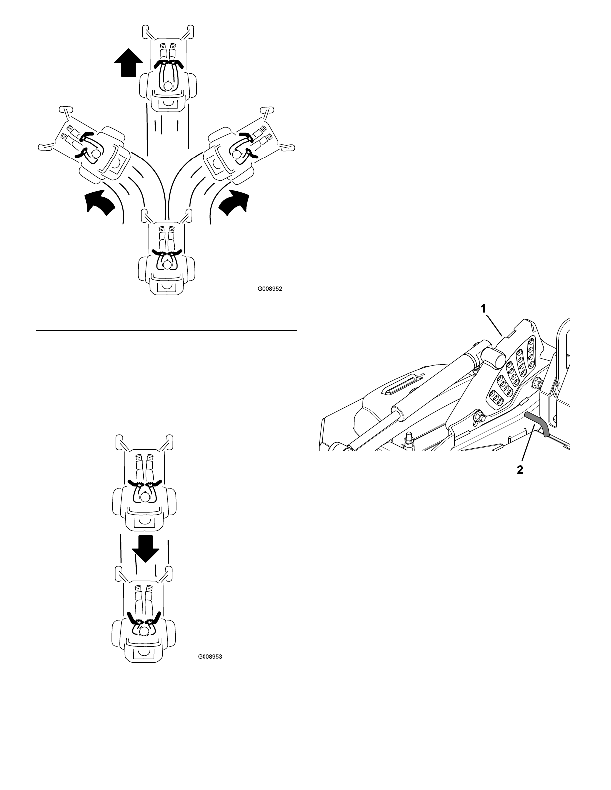
Figure23
AdjustingtheHeightofCut
Adjusttheheightofcutfrom25to140mm(1to5-1/2
inches)in6mm(1/4inch)incrementsbymovingthe
clevispinintodifferentholelocations.
1.Withtheenginerunning,pushthedeck-lift
switchrearwarduntilthemowerdeckisfully
raised,andreleasetheswitchimmediately .
2.Rotatetheheight-of-cutpinuntiltherollpin
initlinesupwiththeslotsintheholesinthe
height-of-cutbracketandremoveit(Figure25).
3.Inserttheheight-of-cutpinintothehole
correspondingtothedesiredcuttingheight
(Figure25).
Refertothedecalonthesideofthedeck-lift
platefortheheightsofcut(Figure25).
4.Usingthedeck-liftswitch,movethedeckheight
outofthetransportposition(or5-1/2inches(140
mm)cuttingheight)anddowntotheselected
g008952
height.
DrivinginReverse
1.Movethemotion-controlleverstothecenter,
unlockedposition.
2.Togoinreverse,slowlypullthemotion-control
leversrearward(Figure24).
g227689
Figure25
1.Height-of-cutbracket2.Height-of-cutpin
Figure24
g008953
27
AdjustingtheAnti-Scalp
Rollers
Formaximumdeckotation,installtherollers1hole
positionlower.Rollersshouldmaintaina6mm(1/4
inch)clearancetotheground.Donotadjustthe
rollerstosupportthedeck.
1.Parkthemachineonalevelsurface.
2.Disengagetheblade-controlswitch(PTO),move
themotion-controlleverstotheNEUTRAL-LOCK
position,andengagetheparkingbrake.
3.Shutofftheengine,removethekey,andwait
forallmovingpartstostopbeforeleavingthe
operatingposition.
4.Adjusttheanti-scalprollersasshowninFigure
26andFigure27.
g227783
Figure27
1.Bolt3.Anti-scalproller
2.Bushing4.Flangenut
5.Torquetheangenutto41to47N∙m(30to35
ft-lb).
Figure26
1.Flangenut3.Bushing
2.Anti-scalproller4.Bolt
g227785
28

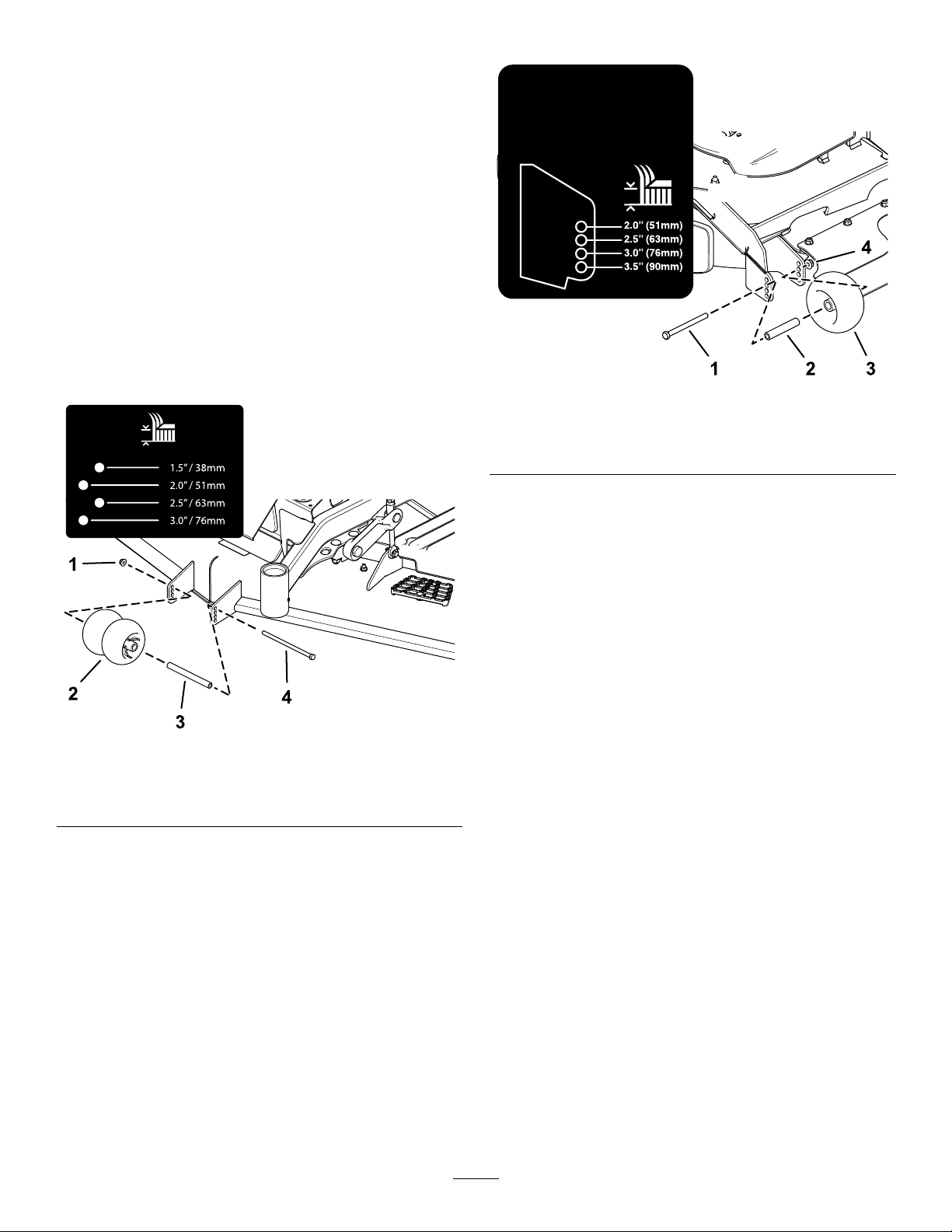
AdjustingtheSkids
Mounttheskidsinthelowerpositionwhenoperating
atheightsofcutgreaterthan51mm(2inches)and
inahigherpositionwhenoperatingatheightsofcut
lowerthan51mm(2inches).
AdjusttheskidsasshowninFigure28.
Figure28
g035646
OperatingwiththeOverheat
Sensor
ThePTOdisengages,analarmsounds,anda
bargraphdisplaystheenginetemperaturewhenit
reachesanoverheatcondition.ThePTOdoesnot
engageuntiltheenginehascooledandyoumanually
shutoffthePTOandengageit.
Note:Iftheengine-coolantlevelisbelowtheindicator
lineontheoverowbottlewhentheengineiscold,the
coolanttemperaturegaugemaynotregistercorrectly
duringoperationand/ortheaudiblealarmmaynot
soundiftheengineoverheats.
29

OperatingTips
UsingtheFastThrottleSetting
dropontoyourlawn.T oavoidthis,moveontoa
previouslycutareawiththebladesengagedoryou
candisengagethemowerdeckwhilemovingforward.
Forbestmowingandmaximumaircirculation,operate
theengineattheFASTposition.Airisrequiredto
thoroughlycutgrassclippings,sodonotsetthe
height-of-cutsolowastototallysurroundthemower
deckinuncutgrass.Alwaystrytohave1sideofthe
mowerdeckfreefromuncutgrass,whichallowsair
tobedrawnintothemowerdeck.
CuttingaLawnfortheFirstTime
Cutgrassslightlylongerthannormaltoensurethat
thecuttingheightofthemowerdeckdoesnotscalp
anyunevenground.However,thecuttingheight
usedinthepastisgenerallythebestonetouse.
Whencuttinggrasslongerthan15cm(6inches)tall,
youmaywanttocutthelawntwicetoensurean
acceptablequalityofcut.
CuttingaThirdoftheGrassBlade
Itisbesttocutonlyaboutathirdofthegrassblade.
Cuttingmorethanthatisnotrecommendedunless
grassissparse,oritislatefallwhengrassgrows
moreslowly.
KeepingtheUndersideofthe
MowerDeckClean
Cleanclippingsanddirtfromtheundersideofthe
mowerdeckaftereachuse.Ifgrassanddirtbuildup
insidethemowerdeck,cuttingqualitywilleventually
becomeunsatisfactory .
MaintainingtheBlade(s)
Maintainasharpbladethroughoutthecuttingseason
becauseasharpbladecutscleanlywithouttearingor
shreddingthegrassblades.T earingandshredding
turnsgrassbrownattheedges,whichslowsgrowth
andincreasesthechanceofdisease.Checkthe
mowerbladesaftereachuseforsharpness,and
foranywearordamage.Filedownanynicksand
sharpenthebladesasnecessary.Ifabladeis
damagedorworn,replaceitimmediatelywitha
genuineT ororeplacementblade.
AlternatingtheMowingDirection
Alternatethemowingdirectiontokeepthegrass
standingstraight.Thisalsohelpsdisperseclippings,
whichenhancesdecompositionandfertilization.
MowingatCorrectIntervals
Grassgrowsatdifferentratesatdifferenttimesof
theyear.Tomaintainthesamecuttingheight,mow
moreofteninearlyspring.Asthegrassgrowthrate
slowsinmidsummer,mowlessfrequently.Ifyou
cannotmowforanextendedperiod,rstmowata
highcuttingheight,thenmowagain2dayslaterata
lowerheightsetting.
UsingaSlowerCuttingSpeed
Toimprovecutquality,useaslowergroundspeed
incertainconditions.
AvoidingCuttingTooLow
Whenmowinguneventurf,raisethecuttingheight
toavoidscalpingtheturf.
StoppingtheMachine
Ifyoumuststoptheforwardmotionofthemachine
whilemowing,aclumpofgrassclippingsmay
30

AfterOperation
AfterOperationSafety
GeneralSafety
•Shutofftheengine,removethekey ,andwait
forallmovingpartstostopbeforeleavingthe
operator’sposition.Allowthemachinetocool
beforeservicing,adjusting,fueling,cleaning,or
storingit.
•Cleangrassanddebrisfromthecuttingunit,
mufer,drives,andenginecompartmenttohelp
preventres.Cleanupoilorfuelspills.
•Shutoffthefuelandremovethekeybeforestoring
ortransportingthemachine.
TransportingtheMachine
Useaheavy-dutytrailerortrucktotransportthe
machine.Useafull-widthramp.Ensurethatthetrailer
ortruckhasallthenecessarybrakes,lighting,and
markingasrequiredbylaw.Pleasecarefullyreadall
thesafetyinstructions.Knowingthisinformationcould
helpyouorbystandersavoidinjury .Refertoyour
localordinancesfortrailerandtie-downrequirements.
WARNING
Drivingonthestreetorroadwaywithout
turnsignals,lights,reectivemarkings,ora
slow-moving-vehicleemblemisdangerous
andcanleadtoaccidents,causingpersonal
injury.
Donotdrivethemachineonapublicstreet
orroadway.
UsingtheDrive-Wheel
ReleaseValves
Usethedrive-wheelreleasevalvestoreleasethe
hydrostaticdrivesystem,whichallowsyoutopushthe
machinewithouttherunningtheengine.
Rotateeachbypassvalvecounterclockwise1turnto
release;rotateeachbypassvalveclockwisetoreset
thesystem(Figure29).
Important:Donotovertighten.Donottowthe
machine.
SelectingaTrailer
WARNING
Loadingamachineontoatrailerortruck
increasesthepossibilityoftip-overandcould
causeseriousinjuryordeath(Figure30).
•Useonlyafull-widthramp;donotuse
individualrampsforeachsideofthe
machine.
•Donotexceeda15-degreeanglebetween
therampandthegroundorbetweenthe
rampandthetrailerortruck.
•Ensurethatthelengthoftherampisat
least4timesaslongastheheightofthe
trailerortruckbedtotheground.This
ensuresthattherampangledoesnot
exceed15degreesonatground.
1.Rightbypassvalve
g004644
Figure29
2.Leftbypassvalve
31

1.Ifusingatrailer,connectittothetowingvehicle
andconnectthesafetychains.
2.Ifapplicable,connectthetrailerbrakesand
lights.
3.Lowertheramp,ensuringthattheangle
betweentherampandthegrounddoesnot
exceed15degrees(Figure30).
4.Backthemachineuptheramp(Figure31).
Figure31
g028043
1.Full-widthrampinstowed
position
2.Sideviewoffull-width
rampinloadingposition
3.Notgreaterthan
15degrees
LoadingtheMachine
Figure30
4.Rampisatleast4times
aslongastheheightof
thetrailerortruckbedto
theground
5.H=heightofthetraileror
truckbedtotheground
6.Trailer
1.Backthemachineupthe
ramp.
2.Drivethemachineforward
downtheramp.
5.Shutofftheengine,removethekey,andengage
theparkingbrake.
6.Tiedownthemachinenearthefrontcaster
wheelsandtherearframewithstraps,chains,
cable,orropes(Figure32).Refertolocal
regulationsfortie-downrequirements.
g027996
g225819
Figure32
1.Tie-downpoints
WARNING
Loadingamachineontoatrailerortruck
increasesthepossibilityoftip-overandcould
causeseriousinjuryordeath.
•Useextremecautionwhenoperatinga
machineonaramp.
•Backthemachineuptherampanddriveit
forwarddowntheramp.
•Avoidsuddenaccelerationordeceleration
whiledrivingthemachineonarampas
thiscouldcausealossofcontrolora
tip-oversituation.
UnloadingtheMachine
1.Lowertheramp,ensuringthattheangle
betweentherampandthegrounddoesnot
exceed15degrees(Figure30).
2.Drivethemachineforwarddowntheramp
(Figure31).
32

Maintenance
MaintenanceSafety
•Checktheparkingbrakeoperationfrequently.
Adjustandserviceitasrequired.
•Nevertamperwithsafetydevices.Checktheir
properoperationregularly.
•Ifyouleavethekeyintheswitch,someonecould
accidentlystarttheengineandseriouslyinjureyou
orotherbystanders.Removethekeyfromthe
switchbeforeyouperformanymaintenance.
•Beforeyouleavetheoperator’sposition,dothe
following:
–Parkthemachineonalevelsurface.
–Disengagethedrives.
–Engagetheparkingbrake.
–Shutofftheengineandremovethekey.
–Allowmachinecomponentstocoolbefore
performingmaintenance.
•Donotallowuntrainedpersonneltoservicethe
machine.
•Keepyourhandsandfeetawayfrommoving
partsorhotsurfaces.Ifpossible,donotmake
adjustmentswiththeenginerunning.
•Carefullyreleasepressurefromcomponentswith
storedenergy.
•Cleangrassanddebrisfromthecuttingunit,
mufer,drives,andenginecompartmenttoprevent
res.
•Cleanupoilorfuelspillsandremovefuel-soaked
debris.
•Donotrelyonhydraulicormechanicaljacksto
supportthemachine;supportthemachinewith
jackstandswheneveryouraisethemachine.
•Keepallpartsingoodworkingcondition
andallhardwaretightened,especiallythe
blade-attachmenthardware.Replaceallwornor
damageddecals.
•Disconnectthebatterybeforerepairingthe
machine.Disconnectthenegativeterminalrst
andthepositivelast.Connectthepositiveterminal
rstandthenegativelast.
•Toensureoptimumperformance,useonly
genuineTororeplacementpartsandaccessories.
Replacementpartsandaccessoriesmadeby
othermanufacturerscouldbedangerous,and
suchusecouldvoidtheproductwarranty.
RecommendedMaintenanceSchedule(s)
MaintenanceService
Interval
Aftertherst100hours
Aftertherst200hours
Beforeeachuseordaily
Every50hours
MaintenanceProcedure
•Checkthewheellugnuts.
•Adjusttheparkingbrake.
•Changetheengineoilandlter.
•Changethedeckgearboxoil.
•Changethehydraulicuidandlter.
•Checkthesafety-interlocksystem.
•Checktheengine-oillevel.
•Checktheseatbelt.
•Checktheengine-coolantlevel.
•Checkthehydraulic-uidlevel.
•Inspecttheblades.
•Cleantheengineandexhaustsystemarea.
•Cleanthegrassanddebrisbuild-upfromthemachineandmowerdeck.
•GreasethedriveU-jointsandsplinedslipjoint.
•Drainthefuellter/waterseparator.
•Checkthetirepressure
•Checkthegearbox-oillevel.
•Cleantheengine-coolingsystem(moreoftenindirtyanddustyconditions).
•Inspectthebeltsforcracksandwear.
Every100hours
Every200hours
•Checkthealternator-belttension.
•ChangetheengineoilandlterifnotusingT oroPremiumEngineOil,butanyoil
meetingAPIclassicationCJ-4orhigherorasstatedinEngine-OilSpecications.
33

MaintenanceService
Every400hours
Interval
MaintenanceProcedure
•Greasethedeck-idlerpivots.
•Greasethecasterpivots(moreoftenindirtyordustyconditions).
•Servicetheaircleaner(Morefrequentlyinextremelydustyordirtyconditions).
•ChangetheengineoilandlterifusingT oroPremiumEngineOil(APIclassication
CK-4orhigher)(moreoftenindirtyordustyconditions).
•Replacethefuel-ltercanisterforthewaterseparator(moreoftenindirtyand
dustyconditions).
•Checkthefuellinesandconnections.
•Changethedeckgearboxoil.
•Adjusttheparkingbrake.
•ChangethehydraulicuidandlterifusingMobil®424hydraulicuid.
Every500hours
Every800hours
Every2,000hours
Monthly
Yearly
•Adjustthecaster-pivotbearing.
•Inspecttheengine-valveclearance.
•ChangethehydraulicuidandlterifusingToroPremiumTransmission/Hydraulic
TractorFluid.
•Changetheenginecoolant.
•Checkthebatterycharge.
•GreasethedeckdrivePTO.
•Repackthecaster-wheelbearings(moreoftenindirtyordustyconditions).
•Greasingthecaster-wheelhubs.
•Ifyouoperatethemachinelessthan200hours,changetheengineoilandlter.
Important:Refertoyourengineowner'smanualforadditionalmaintenanceprocedures.
CAUTION
Ifyouleavethekeyintheswitch,someonecouldaccidentlystarttheengineandseriously
injureyouorotherbystanders.
Shutofftheengineandremovethekeyfromtheswitchbeforeyouperformanymaintenance.
34

Lubrication
GreasingtheMachine
ServiceInterval:Every400hours/Yearly(whichever
comesrst)—Greasethedeck-idler
pivots.
Yearly—GreasethedeckdrivePTO.
Greasemorefrequentlywhenoperatingconditions
areextremelydustyorsandy .
GreaseType:No.2lithiumormolybdenumgrease
1.Parkthemachineonalevelsurface,disengage
theblade-controlswitch,andengagetheparking
brake.
2.Shutofftheengine,removethekey,andwait
forallmovingpartstostopbeforeleavingthe
operatingposition.
3.Cleanthegreasettingswitharag.
Note:Makesurethatyouscrapeanypaintoff
thefrontofthetting(s).
4.Connectagreaseguntothetting.
5.Pumpgreaseintothettingsuntilgreasebegins
tooozeoutofthebearings.
6.Wipeupanyexcessgrease.
Refertothefollowingchartforttinglocationsand
lubricationschedule.
LubricationChart
Fitting
Locations
1.Deck-drive
PTO
2.Deck-idler
pivots
3.
Caster-wheel
bearings
4.Caster
pivots
InitialPumps
13Every50
11Every400
02Yearly
02Every400
Numberof
Places
Service
Interval
hours
hoursor
yearly
hoursor
yearly
LubricatingtheDrive
U-JointsandSplinedSlip
Joint
ServiceInterval:Every50hours—Greasethedrive
U-jointsandsplinedslipjoint.
Note:ForeasieraccesstothedriveU-jointsand
splinedslipjoint,removetheoorpanandfullylower
themowerdeck.
1.Parkthemachineonalevelsurface,disengage
theblade-controlswitch,andengagetheparking
brake.
2.Shutofftheengine,removethekey,andwait
forallmovingpartstostopbeforeleavingthe
operatingposition.
3.Cleanthegreasettingswitharag.
4.Connectagreaseguntothetting.
5.Pumpgreaseintothettingsuntilgreasebegins
tooozeoutofthebearings.
6.Wipeupanyexcessgrease.
g250852
Figure33
35

GreasingtheCasterPivots
ServiceInterval:Every400hours/Yearly(whichever
comesrst)(moreoftenindirtyor
dustyconditions).
Yearly—Repackthecaster-wheelbearings
(moreoftenindirtyordustyconditions).
1.Parkthemachineonalevelsurface,disengage
theblade-controlswitch,andengagetheparking
brake.
2.Shutofftheengine,removethekey,andwait
forallmovingpartstostopbeforeleavingthe
operatingposition.
3.Removethedustcapandadjustthecaster
pivotsandkeepthedustcapoffuntilgreasingis
done;refertoAdjustingtheCaster-PivotBearing
(page44).
4.Removethehexplug.
5.Threadagreasettingintothehole.
6.Pumpgreaseintothettinguntilitoozesout
aroundthetopbearing.
7.Removethegreasettingfromthehole.Install
thehexplugandcap.
6.Removeaspacernutfromtheaxleassemblyin
thecasterwheel.
Note:Thread-lockingcompoundhasbeen
appliedtolockthespacernutstotheaxle.
7.Removetheaxle(withtheotherspacernutstill
assembledtoit)fromthewheelassembly.
8.Pryoutsealsandinspectbearingsforwearor
damageandreplaceifnecessary.
9.Packthebearingswithageneral-purpose
grease.
10.Insert1bearingand1newsealintothewheel.
11.Iftheaxleassemblyismissingbothspacernuts,
applyathread-lockingcompoundto1spacer
nutandthreaditontotheaxlewiththewrench
atsfacingoutward.
Note:Donotthreadthespacernutallof
thewayontotheendoftheaxle.Leave
approximately3mm(1/8inch)fromtheouter
surfaceofthespacernuttotheendoftheaxle
insidethenut.
12.Inserttheassemblednutandaxleintothewheel
onthesidewiththenewsealandbearing.
GreasingtheCaster-Wheel
Hubs
ServiceInterval:Y early
1.Parkthemachineonalevelsurface,disengage
theblade-controlswitch,andengagetheparking
brake.
2.Shutofftheengine,removethekey,andwait
forallmovingpartstostopbeforeleavingthe
operatingposition.
3.Raisethemowerforaccess.
4.Removethecasterwheelfromthecasterforks.
5.Removethesealguardsfromthewheelhub.
Figure34
13.Withtheopenendofthewheelfacingup,ll
theareainsidethewheelaroundtheaxlefullof
general-purposegrease.
14.Insertthesecondbearingandnewsealintothe
wheel.
15.Applyathread-lockingcompoundtothesecond
spacernut,andthreaditontotheaxlewiththe
wrenchatsfacingoutward.
16.T orquethenutto8to9N∙m(75to80in-lb),
loosenthenut,thentorqueitto2to3N∙m(20
to25in-lb).
Note:Makesurethattheaxledoesnotextend
beyondeithernut.
17.Installthesealguardsoverthewheelhub,and
insertthewheelintothecasterfork.
18.Installthecasterboltandtightenthenutfully.
Important:Topreventsealandbearingdamage,
checkthebearingadjustmentoften.Spinthe
castertire.Thetireshouldnotspinfreely(more
than1or2revolutions)orhaveanysideplay .If
thewheelspinsfreely,adjustthetorqueonthe
spacernutuntilthereisaslightamountofdrag.
Applyanotherlayerofthread-lockingcompound.
g006115
1.Sealguard2.Spacernutwithwrench
ats
36

EngineMaintenance
EngineSafety
•Keepyourhands,feet,face,clothing,andother
bodypartsawayfromthemuferandotherhot
surfaces.Allowenginecomponentstocoolbefore
performingmaintenance.
•Donotchangetheenginegovernorspeedor
overspeedtheengine.
ServicingtheAirCleaner
ServiceInterval:Every400hours
CheckingtheAirCleaner
1.Parkthemachineonalevelsurface,disengage
theblade-controlswitch(PTO),andengagethe
parkingbrake.
2.Shutofftheengine,removethekey,andwait
forallmovingpartstostopbeforeleavingthe
operatingposition.
ServicingtheAirCleaner
Note:Ifthefoamgasketinthecoverisdamaged,
replaceit.
Important:Avoidusinghigh-pressureair,which
couldforcedirtthroughthelterintotheintake
tract.
Important:Donotcleantheusedltertoavoid
damagingtheltermedia.
Important:Donotuseadamagedlter.
Important:Donotapplypressuretotheexible
centerofthelter.
3.Checktheair-cleanerbodyfordamage,which
couldpossiblycauseanairleak.
Replaceadamagedair-cleanerbody.
4.Checktheair-intakesystemforleaks,damage,
orloosehoseclamps.
5.Servicetheair-cleanerlterandsafetyelement
whenalerted(Figure35).
Important:Donotover-servicetheairlter.
Figure35
1.Air-cleanerbody4.Filter
2.Gasket
3.Safetyelement
6.Ensurethatthecoverseatscorrectlyandseals
withtheair-cleanerbody.
5.Air-cleanercover
6.Rubberoutletvalve
g332364
g031807
Figure36
37

ServicingtheEngineOil
ServiceInterval:Beforeeachuseordaily
Aftertherst200hours—Changetheengine
oilandlter.
Every200hours—Changetheengineoiland
lterifnotusingToroPremiumEngineOil,but
anyoilmeetingAPIclassicationCJ-4orhigher
orasstatedinEngine-OilSpecications.
Every400hours—Changetheengineoiland
lterifusingT oroPremiumEngineOil(API
classicationCK-4orhigher)(moreoftenin
dirtyordustyconditions).
Yearly—Ifyouoperatethemachinelessthan
200hours,changetheengineoilandlter.
Engine-OilSpecications
Theengineshipswithoilinthecrankcase;however,
checktheoillevelbeforeandafteryourststart
theengine.Checktheoillevelbeforeoperatingthe
machineeachdayoreachtimeyouusethemachine.
Crankcasecapacityfor25HPYanmarDiesel
Engines:4.7L(5USqt)withthelter
Crankcasecapacityfor37HPYanmarDiesel
Engines:6.6L(7USqt)withthelter
3.Openthehood.
4.Checktheengine-oillevelasshowninFigure
37.
g029301
Figure37
Preferredengineoil:T oroPremiumEngineOil
Ifusinganalternateoil,usehigh-quality ,low-ash
engineoilthatmeetsorexceedsthefollowing
specications:
•APIservicecategoryCJ-4orhigher
•ACEAservicecategoryE6
•JASOservicecategoryDH-2
Important:UsingengineoilotherthanAPI
classicationCJ-4orhigher,ACEAE6,orJASO
DH-2maycausethedieselparticulateltertoplug
orcauseenginedamage.
Usethefollowingengineoilviscositygrade:
•SAE10W-30or5W-30(alltemperatures)
•SAE15W-40(above0°F)
Note:ToroPremiumEngineoilisavailablefrom
yourdistributor.SeethePartsCatalogorcontactan
authorizedTorodistributorforpartnumbers.
CheckingtheEngine-OilLevel
1.Parkthemachineonalevelsurface,disengage
theblade-controlswitch(PTO),andengagethe
parkingbrake.
2.Shutofftheengine,removethekey,andwait
forallmovingpartstostopbeforeleavingthe
operatingposition.
38

ChangingtheEngineOilandFilter
Ifpossible,runtheenginejustbeforechangingthe
oilbecausewarmoilowsbetterandcarriesmore
contaminantsthancoldoil.
1.Parkthemachineonalevelsurface,disengage
theblade-controlswitch(PTO),andengagethe
parkingbrake.
2.Shutofftheengine,removethekey,andwait
forallmovingpartstostopbeforeleavingthe
operatingposition.
3.Openthehood.
4.ChangetheengineoilasshowninFigure38.
Figure38
5.Replacetheengine-oillterasshowninFigure
39.
g027477
g031623
6.Fillthecrankcasewithoil;refertoEngine-Oil
Specications(page38).
Figure39
InspectingtheEngine-Valve
Clearance
ServiceInterval:Every800hours
Inspecttheengine-valveclearance.Refertothe
engineowner’smanual.
39
FuelSystem
ReplacingtheWater
Maintenance
DANGER
Incertainconditions,fuelisextremely
ammableandhighlyexplosive.Areor
explosionfromfuelcanburnyouandothers
andcandamageproperty.
RefertoFuelSafety(page17)foracomplete
listoffuelrelatedprecautions.
DrainingtheFuel
Filter/WaterSeparator
ServiceInterval:Every50hours—Drainthefuel
lter/waterseparator.
1.Parkthemachineonalevelsurface,disengage
theblade-controlswitch,andengagetheparking
brake.
2.Shutofftheengine,removethekey,andwait
forallmovingpartstostopbeforeleavingthe
operatingposition.
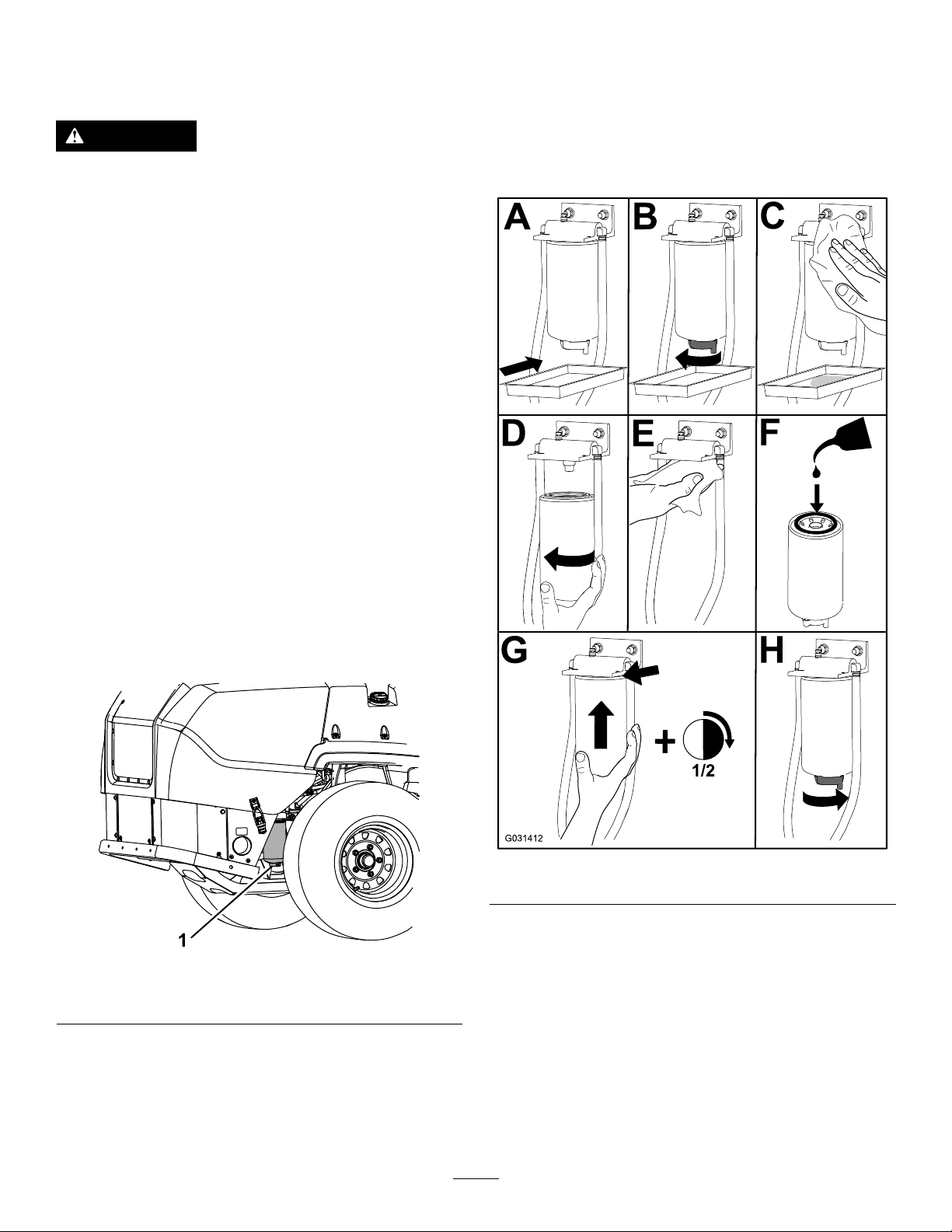
Separator
ServiceInterval:Every400hours—Replacethe
fuel-ltercanisterforthewater
separator(moreoftenindirtyand
dustyconditions).
3.Placeadrainpanbelowthefuellter/water
separator.
4.Openthedrainplugonthewaterseparator
approximately1turntoallowwaterandother
contaminatestodrain(Figure40).
Figure40
1.Fuellter/waterseparator
5.Closethedrainplugwhenonlydieselfuel
comesout.
Important:Waterorothercontaminantsin
fuelcandamagethefuelpumpand/orother
enginecomponents.
g031412
Figure41
g231880
CheckingtheFuelLines
andConnections
ServiceInterval:Every400hours
Inspectthefuellinesfordeterioration,damage,
chafng,orlooseconnections.
40

ElectricalSystem
Maintenance
ElectricalSystemSafety
•Disconnectthebatterybeforerepairingthe
machine.Disconnectthenegativeterminalrst
andthepositivelast.Connectthepositiveterminal
rstandthenegativelast.
•Chargethebatteryinanopen,well-ventilated
area,awayfromsparksandames.Unplugthe
chargerbeforeconnectingordisconnectingthe
battery.Wearprotectiveclothinganduseinsulated
tools.
WARNING
Incorrectbatterycableroutingcoulddamage
themachineandcablescausingsparks.
Sparkscancausethebatterygassesto
explode,resultinginpersonalinjury.
•Alwaysdisconnectthenegative(black)
batterycablebeforedisconnectingthe
positive(red)cable.
•Alwaysconnectthepositive(red)battery
cablebeforeconnectingthenegative
(black)cable.
1.Disengagetheblade-controlswitch(PTO),move
themotion-controlleverstotheNEUTRAL-LOCK
position,andengagetheparkingbrake.
ServicingtheBattery
DANGER
Batteryelectrolytecontainssulfuricacid,
whichisfatalifconsumedandcausessevere
burns.
Donotdrinkelectrolyteandavoidcontact
withskin,eyesorclothing.Wearsafety
glassestoshieldyoureyesandrubbergloves
toprotectyourhands.
RemovingtheBattery
WARNING
Batteryterminalsormetaltoolscouldshort
againstmetalmachinecomponents,causing
sparks.Sparkscancausethebatterygasses
toexplode,resultinginpersonalinjury.
•Whenremovingorinstallingthebattery,
donotallowthebatteryterminalstotouch
anymetalpartsofthemachine.
2.Shutofftheengine,removethekey,andwait
forallmovingpartstostopbeforeleavingthe
operatingposition.
3.Unlatchtheseatandtilttheseatup.
4.RemovethebatteryasshowninFigure42.
•Donotallowmetaltoolstoshortbetween
thebatteryterminalsandmetalpartsofthe
machine.
g032750
Figure42
41

InstallingtheBattery
Note:Positionthebatteryinthetraywiththeterminal
postsoppositefromthehydraulictank.
Note:Donotrunthemachinewiththebattery
disconnected,electricaldamagemayoccur.
g000960
Figure44
Figure43
ChargingtheBattery
ServiceInterval:Monthly—Checkthebatterycharge.
WARNING
Chargingthebatteryproducesgassesthat
canexplode.
Neversmokenearthebatteryandkeepsparks
andamesawayfrombattery .
1.Positivebatterypost
2.Negativebatterypost
3.Red(+)chargerlead
4.Black(-)chargerlead
ServicingtheFuses
Theelectricalsystemisprotectedbyfuses.Itrequires
g032751
nomaintenance,however,ifafuseblowscheck
component/circuitformalfunctionorshort.
1.Unlatchtheenginehoodandraisetheengine
hoodtogainaccesstothefuseblock.
2.T oreplacethefuses,pulloutonthefuseto
removeit.
3.Installanewfuse(Figure45).
Important:Alwayskeepthebatteryfullycharged
(1.265specicgravity).Thisisespecially
importanttopreventbatterydamagewhenthe
temperatureisbelow0°C(32°F).
1.Makesurethatthellercapsareinstalledin
battery.Chargebatteryfor10to15minutesat
25to30Aor30minutesat10A.
2.Whenthebatteryisfullycharged,unplug
thechargerfromtheelectricaloutlet,then
disconnectthechargerleadsfromthebattery
posts(Figure44).
3.Installthebatteryinthemachineandconnect
thebatterycables,refertoInstallingtheBattery
(page42).
g235614
Figure45
1.Accessory(15A)3.Main(25A)
2.Chassis(15A)4.Powerpoint(15A)
42
DriveSystem
Maintenance
CheckingtheSeatBelt
ServiceInterval:Beforeeachuseordaily
Inspecttheseatbeltforwear,cuts,andproper
operationoftheretractorandbuckle.Replacethe
seatbeltifitisdamaged.
AdjustingtheTracking
1.Disengagetheblade-controlswitch(PTO).
2.Drivetoanopenatarea,movethe
motion-controlleverstotheNEUTRAL-LOCK
position.
3.MovethethrottlemidwaybetweentheFASTand
SLOWpositions.
4.Movebothmotion-controlleversalltheway
forwarduntiltheybothhitthestopsintheT-slot.
5.Checkwhichwaythemachinetracks.
6.Engagetheparkingbrake,shutofftheengine,
andremovethekey .
7.Adjustthestopplatesasneeded.
•Ifthemachinetrackstotheright,loosenthe
boltsandadjusttheleftstopplaterearward
ontheleftT-slotuntilthemachinetracks
straight(Figure46).
•Ifthemachinetrackstotheleft,loosenthe
boltsandadjusttherightstopplaterearward
ontherightT-slotuntilthemachinetracks
straight(Figure46).
8.Tightenthestopplate(Figure46).
9.Aligntheleversinthefront-to-rearpositionby
bringingtheleverstogethertotheNEUTRAL
position,andslidethemuntiltheyarealigned,
thentightenthebolts(Figure47).
g009195
Figure47
10.Ifalignmentisneeded,loosenthe2
motion-controllevermountingboltsonthe
misalignedside(Figure48).
Figure46
1.Controllever3.Stopplate
2.Bolt
g254283
Figure48
11.Movemotion-controllevertomeettheopposite
g254284
43
side.
12.Tightenthe2motion-controllevermounting
bolts(Figure48).
CheckingtheTirePressure
AdjustingtheCaster-Pivot
ServiceInterval:Every50hours/Monthly(whichever
comesrst)
Reartireairpressurespecication:124kPa(18
psi).
Note:Thecastertiresaresemi-pneumatictiresand
donotrequireairpressuremaintenance.
DANGER
Lowtirepressuredecreasesmachineside-hill
stability.Thiscouldcausearollover,which
mayresultinpersonalinjuryordeath.
Donotunder-inatethetires.
Checktheairpressureinthereartires.Addorremove
airasneededtosettheairpressureinthetirestothe
tireairpressurespecication.
Important:Maintainpressureinalltiresto
ensureagoodqualityofcutandpropermachine
performance.
Checktheairpressureinallthetiresbefore
operatingthemachine.
Bearing
ServiceInterval:Every500hours/Yearly(whichever
comesrst)
1.Parkthemachineonalevelsurface,disengage
theblade-controlswitch,andengagetheparking
brake.
2.Shutofftheengine,removethekey,andwait
forallmovingpartstostopbeforeleavingthe
operatingposition.
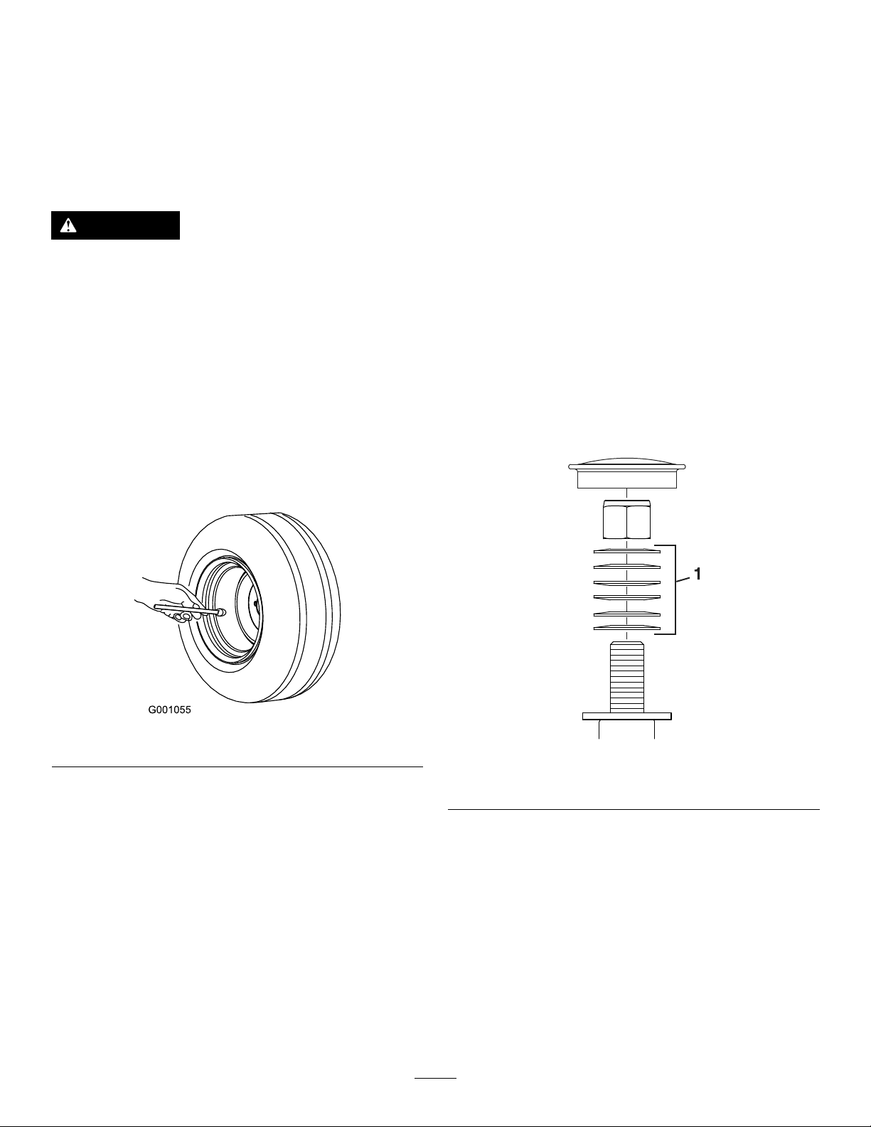
3.Removethedustcapfromthecasterandtighten
thelocknut(Figure50).
4.Tightenthelocknutuntilthespringwashersare
at,andthenbackoffa1/4turntoproperlyset
thepreloadonthebearings(Figure50).
Important:Makesurethatthespring
washersareinstalledcorrectlyasshownin
Figure50.
5.Installthedustcap(Figure50).
Figure49
CheckingtheWheelLug
Nuts
ServiceInterval:Aftertherst100hours—Checkthe
wheellugnuts.
Torquethewheellugnutsto115to142N∙m(85to
105ft-lb).
g001055
g228558
Figure50
1.Springdiscwashers
44

ServicingtheGearbox
CheckingtheGearbox-OilLevel
ChangingtheGearboxOil
ServiceInterval:Aftertherst200hours
Every400hours
ServiceInterval:Every50hours
UseSAE75W-90syntheticgearlube.
1.Parkthemachineonalevelsurfaceandengage
theparkingbrake.
2.Lowerthemowerdecktothe25mm(1inch)
heightofcut.
3.Disengagetheblade-controlswitch,shutoffthe
engine,removethekey ,andwaitforallmoving
partstostopbeforeleavingtheoperating
position.
4.Liftthefootresttoexposethetopofthemower
deck.
5.Removethedipstick/llplugfromthetopofthe
gearboxandensurethatthelubricantisbetween
themarksonthedipstick(Figure51).
Iftheoilbecomescontaminated,contactyourT oro
Distributorbecausethesystemmustbeushed.
Contaminatedoillooksmilkyorblackwhencompared
tocleanoil.
1.Parkthemachineonalevelsurfaceandengage
theparkingbrake.
2.Lowerthemowerdecktothe25mm(1inch)
heightofcut.
3.Disengagetheblade-controlswitch,shutoffthe
engine,removethekey ,andwaitforallmoving
partstostopbeforeleavingtheoperating
position.
4.Liftthefootresttoexposethetopofthemower
deck.
5.Removethedipstick/llplugfromthetopofthe
gearboxandensurethatthelubricantisbetween
themarksonthedipstick(Figure51).
6.Extracttheoilthroughthellportusinga
vacuumdeviceorremovethegearboxfromthe
deckandpourouttheoilintoadrainpan.
7.Installthegearbox(ifitwasremovedtodrain).
Figure51
1.Fillplug/dipstick
6.Iftheoillevelislow,addenoughlubricantuntil
thelevelisbetweenthemarksonthedipstick.
Important:Donotoverllthegearbox;
overllingthegearboxmaydamageit.
8.Addapproximately420ml(14oz),untilthe
levelisbetweenthemarksonthedipstick
Important:Donotoverllthegearbox;
overllingthegearboxmaydamageit.
g231764
45

CoolingSystem
Maintenance
CoolingSystemSafety
•Swallowingenginecoolantcancausepoisoning;
keepoutofreachfromchildrenandpets.
•Dischargeofhot,pressurizedcoolantortouching
ahotradiatorandsurroundingpartscancause
severeburns.
–Alwaysallowtheenginetocoolatleast15
minutesbeforeremovingtheradiatorcap.
–Usearagwhenopeningtheradiatorcap,and
openthecapslowlytoallowsteamtoescape.
g227787
Figure52
1.Expansion-tankcap3.Addline
2.Fullline
Checkingthe
Engine-CoolantLevel
ServiceInterval:Beforeeachuseordaily
Coolantspecication:50/50solutionofwaterand
permanentethylene-glycolantifreeze
Cooling-systemcapacity:7.6L(8USqt)
1.Parkthemachineonalevelsurface,disengage
theblade-controlswitch,andengagetheparking
brake.
2.Shutofftheengine,removethekey,andwait
forallmovingpartstostopbeforeleavingthe
operatingposition.
3.Openthehood.
4.Checkthelevelofthecoolantintheexpansion
tank(Figure52).
Note:Thecoolantlevelshouldbebetweenthe
marksonthesideofthetank.
5.Ifcoolantlevelislow,removetheexpansion-tank
cap,andaddthespeciedcoolant(Figure52).
Important:Donotoverll.
6.Installtheexpansion-tankcap.
7.Closethehood.
CleaningtheRadiator
ServiceInterval:Every50hours—Cleanthe
engine-coolingsystem(moreoften
indirtyanddustyconditions).
Cleantheradiatortopreventtheenginefrom
overheating.
Note:Ifthemowerdeckorengineshutsoffdueto
overheating,checktheradiatorforexcessivebuildup
ofdebris.
1.Parkthemachineonalevelsurface,disengage
theblade-controlswitch,andengagetheparking
brake.
2.Shutofftheengine,removethekey,andwait
forallmovingpartstostopbeforeleavingthe
operatingposition.
3.Rotatethehoodforward.
4.Usingcompressedair,blowoutdebrisstuck
betweenthensoftheentireradiator,bothfrom
thetopdownandbottomup.
5.Ifdebrisremains,itmaybenecessarytouse
waterfromalow-pressurehose.
Iftheradiatorisclean,proceedtostep7.
6.Covertheenginewithapieceofcardboardor
aplasticsheet.Squirtwaterthroughthens.
Blowthroughwithlow-pressureairfromboth
directions.
46

Note:Ifdebrisremains,repeatuntilclean.
7.Lowerthehood.
8.Starttheenginetoensurethatthefanfunctions
properly.
9.Operateengineuntiltheenginethermostat
opensandthecoolantiscirculatingthroughthe
radiatorcore.
Asairpurgesfromtheengineblockandthe
coolantleveldrops,addadditionalcoolanttothe
radiator.
ChangingtheEngine
Coolant
ServiceInterval:Every2,000hours/Every2years
(whichevercomesrst)
1.Parkthemachineonalevelsurface,disengage
theblade-controlswitch,andengagetheparking
brake.
2.Shutofftheengine,removethekey,andwait
forallmovingpartstostopbeforeleavingthe
operatingposition.
3.Rotatethehoodforward.
4.Drainthecoolantwhentheengineiscool.
5.Removetheradiatorcap,placeapanunder
theradiator,andremovethedrainplugatthe
bottomoftheradiator.
6.Removethecoolanthosefromtheoilcoolerand
drainthecoolantfromtheengineblock(Figure
53).
10.Whentheradiatoriscompletelyfullandno
additionalcoolantcanbeadded,continue
runningandinstalltheradiatorcap.
Ensurethatthecapiscompletelyseatedby
pressingdownrmlywhileturning,untilthecap
stops.Oncethecapisinstalled,shutoffthe
engine.
Figure53
1.Coolanthose
7.Installthedrainplugsandhoses.
8.Fillradiatorwitha50/50mixofwaterand
ethyleneglycol.
Note:TheuseofHavoline
coolantisrecommended.
Allowsomeroom(approximately12.7mm(1/2
inch))forexpansion.Add50/50coolantmixto
theoverowbottleontheleftsideoftheengine
asrequiredtobringtheleveluptotheindicator
lineonthebottle.
XtendedLife
®
g233651
47

BrakeMaintenance
AdjustingtheParking
Brake
ServiceInterval:Aftertherst100hours
Every400hours
Checktoensurethatparkingbrakeisadjusted
properly.Followthisprocedurealsowheneveryou
haveremovedorreplacedabrakecomponent.
1.Parkthemachineonalevelsurface,disengage
theblade-controlswitch,andengagetheparking
brake.
2.Shutofftheengine,removethekey,andwait
forallmovingpartstostopbeforeleavingthe
operatingposition.
3.Raisetherearofthemachineupandsupport
themachinewithjackstands.
4.Removethereartiresfromthemachine.
5.Removeanydebrisfromthebrakearea.
6.Releasethedrivewheels;refertoUsingthe
Drive-WheelReleaseValves(page31).
7.Measurethelengthofthelinkassembly(Figure
54).
Note:Ifthelinkassemblyisattachedinthe
frontposition,thelengthshouldbe219mm
(8-5/8inches);ifitisattachedintherear
position,thelengthshouldbe232mm(9-1/8
inches).
Figure54
1.Frontlocation
2.Rearlocation6.Linkassembly
3.95mm(3-3/4inches)
4.Gap
8.Measurethelengthofthespring(Figure54).
5.Spring
7.Length
Note:Themeasurementshouldbe95mm
(3-3/4inches).
g228555
9.Whenyouachievethecorrectspringlength,
checktoseeifthereisavisiblegapbetweenthe
trunionandtheshoulder.
10.Disengagetheparkingbrakeandturnthewheel
hubbyhandinbothdirections.
Note:Thewheelhubshouldmovefreely .
11.Ifagapisneededorthewheelhubdoesmove
freely,dothefollowing:
A.Disengagetheparkingbrake.
B.Disconnectandne-tunetherearlinkage
assembly.
•Shortenthelinktocreateagap.
•Lengthenthelinktoallowwheelhub
movement.
C.Connecttherearlinkageassembly.
12.Engagetheparkingbrakeandcheckthegap.
48

13.Repeatsteps10through12untilavisiblegap
isachievedandthewheelhubrotatesfreely.
Repeatthisprocedurefortheotherside.
BeltMaintenance
Note:Thebrakeshouldfullydisengagewhen
thebrakeisinthereleasedposition.
14.Rotatethedrivewheelreleasehandleto
theoperatingposition;refertoUsingthe
Drive-WheelReleaseValves(page31).
15.Installthereartiresandtorquethelugnutsto
115to142N∙m(85to105ft-lb).
16.Removethejackstands.
InspectingtheBelts
ServiceInterval:Every50hours
Replacethebeltifitisworn.Thesignsofawornbelt
includesquealingwhilethebeltisrotating;theblades
slippingwhilecuttinggrass;andfrayededges,burn
marks,andcracksonthebelt.
ReplacingtheMowerBelt
Squealingwhenthebeltisrotating,bladesslipping
whencuttinggrass,frayedbeltedges,burnmarks
andcracksaresignsofawornmowerbelt.Replace
thebeltifanyoftheseconditionsareevident.
1.Parkthemachineonalevelsurface,disengage
theblade-controlswitch,andengagetheparking
brake.
2.Shutofftheengine,removethekey,andwait
forallmovingpartstostopbeforeleavingthe
operatingposition.
3.Lowerthemowertothe76mm(3inches)height
ofcut.
4.Removethebeltcovers.
5.Usearatchetinthesquareholeintheidlerarm
toremovetensionontheidlerspring(Figure55).
6.Removethebeltfromthemower-deckpulley.
7.Installthenewbeltaroundthemowerpulleys
(Figure55).
Figure55
g235768
1.Spring3.Spring-loadedidlerpulley
2.Squareholeintheidler
armfortheratchet
8.Ensurethatthespringendsareseatedinthe
anchorgrooves,andusingtheratchetinthe
49
4.Mowerbelt

squarehole,installthebeltaroundtheidler
pulley(Figure55).
9.Installthebeltcovers.
Checkingthe
Alternator-BeltTension
ServiceInterval:Every100hours
1.Apply44N(10lb)offorcetothealternatorbelt,
midwaybetweenthepulleys.
2.Ifthedeectionisnot10mm(3/8inch),loosen
thealternatormountingbolts(Figure56).
Figure56
1.Mountingbolt2.Alternator
3.Increaseordecreasethealternator-belttension.
4.Tightenthemountingbolts.
5.Checkthedeectionofthebeltagaintoensure
thatthetensioniscorrect.
g008932
50

ControlsSystem
Maintenance
Adjustingthe
Control-HandlePosition
Thereare2heightpositionsforthecontrol
levers—highandlow.Removetheboltstoadjustthe
heightfortheoperator.
1.Parkthemachineonalevelsurface,disengage
theblade-controlswitch(PTO),andengagethe
parkingbrake.
2.Shutofftheengine,removethekey,andwait
forallmovingpartstostopbeforeleavingthe
operatingposition.
3.Loosentheboltsandangenutsinstalledinthe
levers(Figure57).
g009195
Figure58
4.Aligntheleversinthefront-to-rearpositionby
bringingtheleverstogethertotheNEUTRAL
position,andslidethemuntiltheyarealigned,
thentightenthebolts(Figure58).
Figure57
1.Bolt
2.Handle4.Nut
3.Controllever
5.Iftheendsofthelevershitagainsteachother,
refertoAdjustingtheMotion-ControlLinkage
(page51).
6.Repeattoadjustthecontrollevers.
Adjustingthe
Motion-ControlLinkage
Locatedoneithersideofthemachine,belowtheseat,
arethepump-controllinkages.Rotatingtheendnut
witha1/2-inchdeepsocketwrenchallowsnetuning
adjustmentssothatthemachinedoesnotmovein
neutral.Anyadjustmentsshouldbemadeforneutral
positioningonly.
g009040
WARNING
Toadjustthemotioncontrol,youmustrun
theengineandturnthedrivewheels.Contact
withmovingpartsorhotsurfacesmaycause
personalinjury.
Keepyourngers,hands,andclothingclear
ofrotatingcomponentsandhotsurfaces.
1.Parkthemachineonalevelsurface,disengage
theblade-controlswitch(PTO),andengagethe
parkingbrake.
2.Shutofftheengine,removethekey,andwait
forallmovingpartstostopbeforeleavingthe
operatingposition.
3.Pushthedeck-liftpedal,removetheheight-of-cut
pin,andlowerthemowerdecktotheground
51
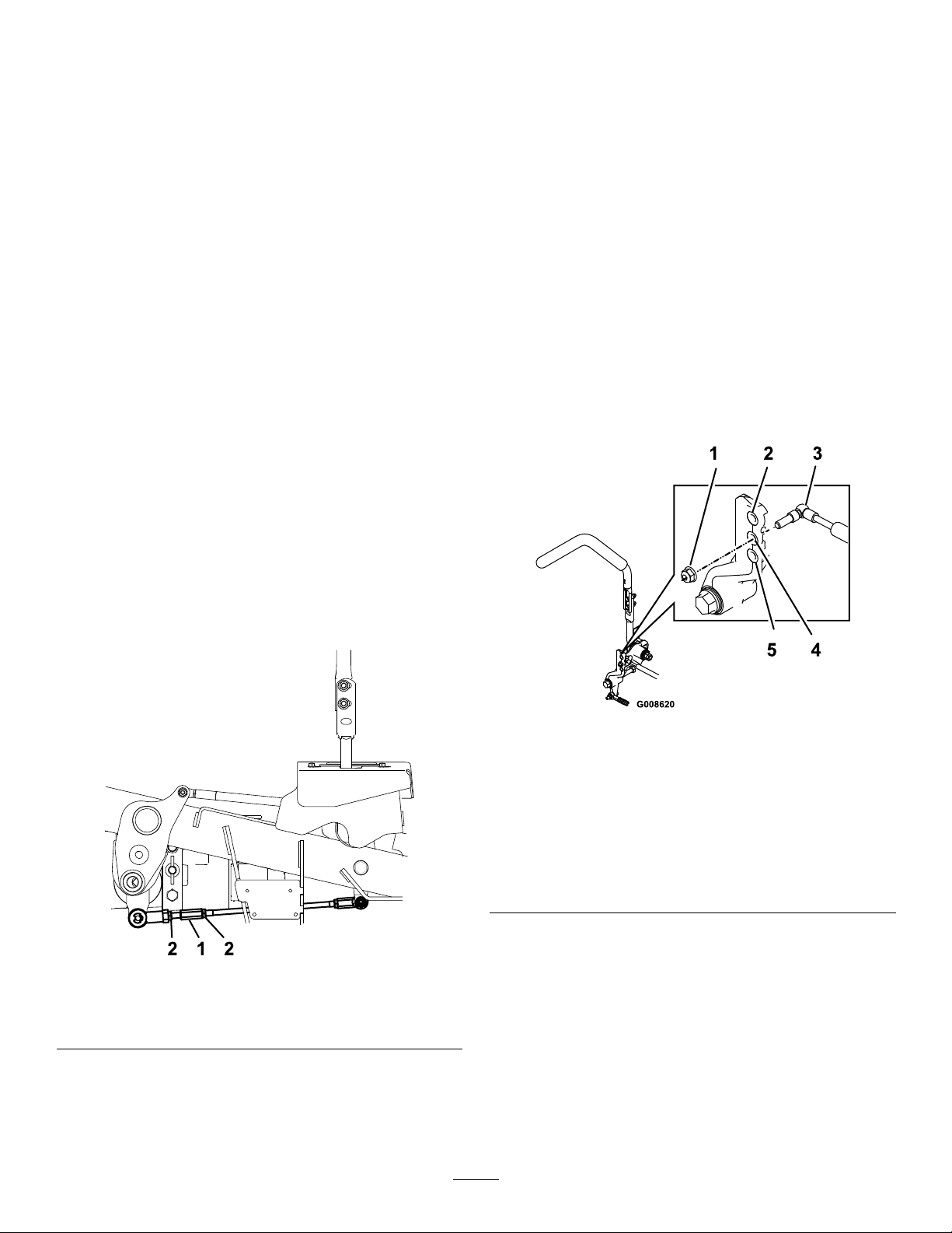
4.Raisetherearofthemachineupandsupportit
withjackstands(orequivalentsupport)justhigh
enoughtoallowthedrivewheelstoturnfreely .
5.Removetheelectricalconnectionfromtheseat
safetyswitch,locatedunderthebottomcushion
oftheseat.
Note:Theswitchisapartoftheseatassembly .
6.Temporarilyinstallajumperwireacrossthe
terminalsintheconnectorofthemainwire
harness.
7.Starttheengine,runitatfullthrottle,and
disengagetheparkingbrake.
Note:Thewheelsshouldstopturningorslightly
creepinreverse.
12.Shutoffthemachine.
13.Removethejumperwirefromthewireharness
andplugtheconnectorintotheseatswitch.
14.Removethejackstands.
15.Raisethedeckandinstalltheheight-of-cutpin.
16.Checkandensurethatthemachinedoes
notcreepinneutralwiththeparkingbrake
disengaged.
Note:Beforestartingtheengine,ensurethat
theparkingbrakeisengagedandthatthe
motion-controlleversareout.Y oudonothave
tobeintheseat.
8.Runthemachineatleast5minuteswiththe
driveleversatfullforwardspeedtobringthe
hydraulicuiduptotheoperatingtemperature.
Note:Themotion-controlleversmustbein
neutralwhileyouaremakinganyadjustments.
9.Bringthemotion-controlleversintotheNEUTRAL
position.
10.Adjustthepumpcontrolrodlengthsbyrotating
thedoublenutsontherodintheappropriate
directionuntilthewheelsslightlycreepin
reverse(Figure59).
Adjustingthe
Motion-ControlDamper
Youcanadjustthetopdamper-mountingbolttoobtain
thedesiredmotion-controlleverresistance.Referto
Figure60formountingoptions.
g008620
Figure60
RightMotionControlShown
Figure59
1.Turnheretoadjust.
2.Loosenhere(right-hand
thread).
11.Movethemotion-controlleverstotheREVERSE
positionandwhileapplyingslightpressureto
thelever,allowthereverse-indicatorspringsto
bringtheleversbacktoneutral.
1.Torquethelocknutto23N∙m(17ft-lb).Theboltmust
protrudepasttheendofthelocknutaftertorquing.
2.Mostresistance(rmestfeel)
3.Damper
4.Mediumresistance(mediumfeel)
5.Leastresistance(softestfeel)
g228557
52
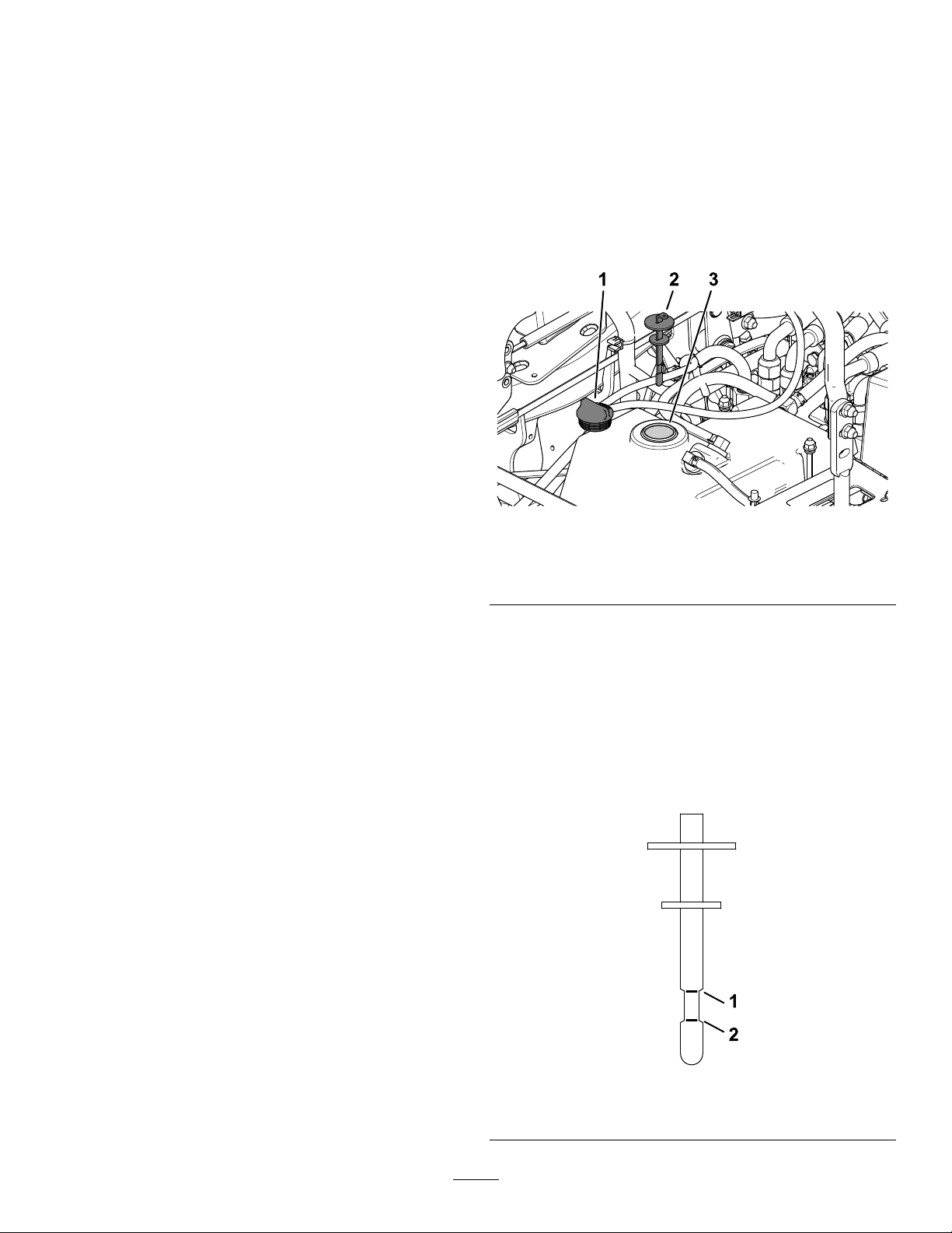
HydraulicSystem
2.Movethemotion-controlleverstothe
NEUTRAL-LOCKpositionandstarttheengine.
Maintenance
HydraulicSystemSafety
•Seekimmediatemedicalattentionifuidisinjected
intoskin.Injecteduidmustbesurgicallyremoved
withinafewhoursbyadoctor.
•Ensurethatallhydraulic-uidhosesandlinesare
ingoodconditionandallhydraulicconnections
andttingsaretightbeforeapplyingpressureto
thehydraulicsystem.
•Keepyourbodyandhandsawayfrompinhole
leaksornozzlesthatejecthigh-pressurehydraulic
uid.
•Usecardboardorpapertondhydraulicleaks.
•Safelyrelieveallpressureinthehydraulicsystem
beforeperforminganyworkonthehydraulic
system.
ServicingtheHydraulic
System
Note:Runtheengineatthelowestpossible
rpmtopurgeanyairinthesystem.
Important:DonotengagethePTO.
3.Raisethedecktoextendtheliftcylinders,shut
offtheengine,andremovethekey.
4.Raisetheseattoaccessthehydraulic-uidtank.
5.Removethehydraulic-tankcap(Figure61).
g227849
Figure61
Hydraulic-FluidSpecications
Hydraulic-tankcapacity:15.1L(16USqt)
Recommendeduid:T oroPremium
Transmission/HydraulicTractorFluid(availablein
5-gallonpailsor55-gallondrums.SeetheParts
CatalogorcontactanauthorizedT orodistributorfor
partnumbers.)
Alternateuids:IftheT orouidisnotavailable,
Mobil®424hydraulicuidmaybeused.
Note:T orodoesnotassumeresponsibilityfor
damagecausedbyimpropersubstitutions.
Note:Manyhydraulicuidsarealmostcolorless,
makingitdifculttospotleaks.Areddyeadditive
forthehydraulic-systemuidisavailablein20ml
(2/3oz)bottles.1bottleissufcientfor15to22L
(4to6gallons)ofhydraulicuid.OrderPartNumber
44-2500fromyourauthorizedT orodistributor.
CheckingtheHydraulic-Fluid
Level
1.Hydraulic-tankcap3.Fillerneck
2.Dipstick
6.Removethedipstickandwipeitwithacleanrag
(Figure61).
7.Placethedipstickintothellerneck,removeit,
andchecktheuidlevel(Figure62).
Note:Ifthelevelisnotwithinthenotchedarea
ofthedipstick,addenoughhigh-qualityhydraulic
uidtoraisetheleveltowithinthenotchedarea.
Important:Donotoverll.
ServiceInterval:Beforeeachuseordaily
Checkthehydraulic-uidlevelbeforeyourststart
theengineanddailythereafter.
1.Parkthemachineonalevelsurface,disengage
theblade-controlswitch,andengagetheparking
brake.
g228816
Figure62
1.Fullline2.Addline
53

8.Replacethedipstickandthreadthellcap
nger-tightontothellerneck.
9.Checkallhosesandttingsforleaks.
ChangingtheHydraulicFluidand
Filter
ServiceInterval:Aftertherst200hours—Change
thehydraulicuidandlter.
Every400hours—Changethehydraulicuid
andlterifusingMobil®424hydraulicuid.
Every800hours—Changethehydraulic
uidandlterifusingT oroPremium
Transmission/HydraulicTractorFluid.
1.DisengagethePTO,movethemotion-control
leverstotheNEUTRAL-LOCKposition,and
engagetheparkingbrake.
2.MovethethrottlelevertotheSLOWposition,
shutofftheengine,removethekey,andwait
forallmovingpartstostopbeforeleavingthe
operatingposition.
3.Raisetheseat.
4.Placealargedrainpanunderthehydraulic
reservoir,transmissioncase,andtheleftand
rightwheelmotors(Figure63).
6.Cleantheareaaroundthehydraulic-uidlter
andremovethelter(Figure63).
7.Installanewhydraulic-uidlterandturnthe
lterclockwiseuntiltherubbersealcontactsthe
lteradapter,thentightenthelteranadditional
2/3to3/4turn.
8.Installthe4drainplugs.
Note:Thewheelmotordrainplugsare
magnetic;wipethemcleanbeforeinstalling.
9.Removethell-portplugonthetopofeach
wheelmotor(Figure64).
A.Filleachwheelmotorwithapproximately
1.4L(1.5USqt)ofT oroPremium
Transmission/HydraulicTractorFluid.
B.Installthell-portplugs.
Figure63
1.Rearframe
2.Leftwheelmotordrain
plug
3.Hydraulicreservoirdrain
plug
4.Transmissioncasedrain
plug
5.Rightwheelmotordrain
plug
6.Hydraulic-uidlter
5.Removethedrainplugsfromeachareaand
allowthehydraulicuidtodrain(Figure63).
g235097
Figure64
1.Fillport
10.Removethereservoircapanddipstickfromthe
hydraulic-uidtank.
11.Add7.6L(8USqt)ofuidtothereservoir.
12.Raisetherearofmachineupandsupportitwith
g231945
jackstands(orequivalentsupport)justhigh
enoughtoallowthedrivewheelstoturnfreely .
13.Starttheengineandcheckforuidleaks.
Allowtheenginetorunforabout5minutes,then
shutitoff.
14.After2minutes,checkthelevelofthehydraulic
uid;refertoCheckingtheHydraulic-FluidLevel
(page53).
54

MowerDeck
Maintenance
BladeSafety
•Inspectthebladesperiodicallyforwearordamage.
•Usecarewhencheckingtheblades.Wrapthe
bladesorweargloves,andusecautionwhen
servicingtheblades.Onlyreplaceorsharpenthe
blades;neverstraightenorweldthem.
•Onmulti-bladedmachines,takecareasrotating
onebladecancauseotherbladestorotate.
•Replacewornordamagedbladesandboltsinsets
topreservebalance.
ServicingtheCutting
Blades
Toensureasuperiorqualityofcut,keeptheblades
sharp.Forconvenientsharpeningandreplacement,
youmaywanttokeepextrabladesonhand.
BeforeInspectingorServicingthe
Blades
1.Parkthemachineonalevelsurface,disengage
theblade-controlswitch,andengagetheparking
brake.
g006530
Figure65
1.Cuttingedge3.Wear/slotforming
2.Curvedarea4.Crack
CheckingforBentBlades
Note:Themachinemustbeonalevelsurfacefor
thefollowingprocedure.
1.Raisethemowerdecktothehighest
height-of-cutposition.
2.Whilewearingthicklypaddedgloves,orother
adequatehandprotection,slowlyrotatethe
bladeintoapositionthatallowsyoutomeasure
thedistancebetweenthecuttingedgeandthe
levelsurfacethemachineison(Figure66).
2.Shutofftheengine,removethekey,andwait
forallmovingpartstostopbeforeleavingthe
operatingposition.
InspectingtheBlades
ServiceInterval:Beforeeachuseordaily
1.Inspectthecuttingedges(Figure65).
2.Iftheedgesarenotsharporhavenicks,remove
andsharpentheblade;refertoSharpeningthe
Blades(page57).
3.Inspecttheblades,especiallyinthecurvedarea.
4.Ifyounoticeanycracks,wear,oraslotforming
inthisarea,immediatelyinstallanewblade
(Figure65).
g014972
Figure66
1.Deck3.Blade
2.Spindlehousing
3.Measurefromthetipofthebladetotheat
surface(Figure67).
55

Figure67
g014973
Figure69
g014973
1.Blade(inpositionformeasuring)
2.Levelsurface
3.Measureddistancebetweenbladeandthesurface(A)
4.Rotatethesameblade180degreessothat
theopposingcuttingedgeisnowinthesame
position(Figure68).
Figure68
1.Blade(sidepreviouslymeasured)
2.Measurement(positionusedpreviously)
3.Opposingsideofbladebeingmovedintomeasurement
position
1.Oppositebladeedge(inpositionformeasuring)
2.Levelsurface
3.Secondmeasureddistancebetweenbladeandsurface(B)
A.IfthedifferencebetweenAandBisgreater
than3mm(1/8inch),replacethebladewith
anewblade;refertoRemovingtheBlades
(page56)andInstallingtheBlades(page
57).
Note:Ifabentbladeisreplacedwitha
newblade,andthedimensionobtained
continuestoexceed3mm(1/8inch),the
bladespindlecouldbebent.Contactan
AuthorizedServiceDealerforservice.
B.Ifthevarianceiswithinconstraints,moveto
thenextblade.
g014974
6.Repeatthisprocedureoneachblade.
RemovingtheBlades
Replacethebladesiftheyhitasolidobject,orifthe
bladeisoutofbalanceorbent.
5.Measurefromthetipofthebladetotheat
surface(Figure69).
Note:Thevarianceshouldbenomorethan
3mm(1/8inch).
1.Placeawrenchontheatofthespindleshaftor
holdthebladeendusingaragorthicklypadded
glove.
2.Removethebladebolt,bushing,andbladefrom
thespindleshaft(Figure70).
56

Figure70
g000553
Figure72
1.Blade2.Balancer
3.Repeatthisprocedureuntilthebladeis
balanced.
InstallingtheBlades
1.Installthebushingthroughthebladewiththe
bushingangeonthebottom(grass)sideofthe
blade(Figure73).
g295816
1.Sailareaoftheblade
2.Blade5.Bladebolt
3.Flatofthespindleshaft
4.Bushing
SharpeningtheBlades
1.Usealetosharpenthecuttingedgeatboth
endsoftheblade(Figure71).
Note:Maintaintheoriginalangle.
Note:Thebladeretainsitsbalanceifthesame
amountofmaterialisremovedfrombothcutting
edges.
Figure71
1.Sharpenatoriginalangle.
g255205
Figure73
1.Bushing
2.Installthebushing/bladeassemblyintothe
spindleshaft(Figure74).
g000552
2.Checkthebalanceofthebladebyputtingitona
bladebalancer(Figure72).
Note:Ifthebladestaysinahorizontalposition,
thebladeisbalancedandcanbeused.
Note:Ifthebladeisnotbalanced,lesome
metalofftheendofthesailareaonly(Figure71).
g298850
Figure74
1.Topspindlenut3.Bladebolt
2.Flatofthespindleshaft
57
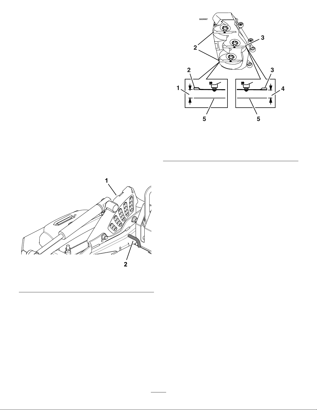
3.Applycopper-basedlubricantorgreasetothe
threadsofthebladeboltasneededtoprevent
seizing.Installthebladeboltnger-tight.
4.Placeawrenchontheatofthespindleshaft
andtorquethebladeboltto75to81N∙m(55
to60ft-lb).
LevelingtheMowerDeck
Note:Ensurethatthemowerdeckislevelbefore
matchingtheheightofcut(HOC).
1.Parkthemachineonalevelsurface,disengage
theblade-controlswitch,andengagetheparking
brake.
2.Shutofftheengine,removethekey,andwait
forallmovingpartstostopbeforeleavingthe
operatingposition.
3.Checktirepressureofthedrivetires.
Ifneeded,adjustto124kPa(18psi).
4.Usingthedeck-liftswitch,movethedeckheight
outofthetransportposition(140mm/5-1/2
inchescuttingheight).
Figure75
g009997
Figure76
1.76mm(3inches)4.76mm(3inches)
2.Rearbladetip
3.Frontbladetip
5.Levelsurface
8.Fine-tunetheadjustmentnutonthefrontdeck
liftassemblybyturningit(Figure77).
Note:T oincreasetheheight,turnthe
adjustmentnutclockwise;todecrease,turnit
counterclockwise.
Note:Ifthefrontdecklinksdonothaveenough
adjustmenttoachieveaccuratecuttingheight,
youcanusethesingle-pointadjustmenttogain
moreadjustment.
g227689
1.Height-of-cutbracket2.Height-of-cutpin
5.Inserttheheight-of-cutpinintothe76mm(3
inches)height-of-cutlocation.
6.Releasethetransportlockandallowthedeckto
lowertothecuttingheight.
7.Measurefromthelevelsurfacetothefronttipof
thecenterblade(Figure76).
Note:Themeasurementshouldread76mm
(3inches).
Inmostconditions,thebacktipsontheside
bladesshouldbelevelwiththefront.
58

Figure78
g232012
Figure77
1.Deckadjustment3.Adjustmentnut
2.Jamnut
9.Measuretherearbladetipheight.Fine-tunethe
rearadjustersasrequired;usethesingle-point
adjustmenttogainmoreadjustment.
Thereartipsofthesidebladesshouldmeasure
76mm(3inches).
10.Measureuntilall4sidesarethecorrect
height.Tightenallthenutsonthedeck-liftarm
assemblies.
11.Ifthe4deckadjustersdonothaveenough
adjustmenttoachievetheaccurateheightof
cutwiththedesiredrake,youcanadjustthe
single-pointsystem(Figure78).
1.Single-pointheight
adjustmentbolt
g231991
2.Frontheight-of-cutplate
mountingbolt
3.Rearheight-of-cutplate
mountingbolt
12.T oadjustthesingle-pointsystem,rstloosen
thefrontandrearheight-of-cutplatemounting
bolts(Figure78).
Note:Themowerdeckisattachedinthefront
holesatthefactory(Figure79).Ifneeded,use
thebackholesforfurtheradjustmentwhen
levelingthemowerdeck.
Figure79
1.Mowerdeck3.Backhole
2.Fronthole
13.Ifthedeckistoolow,tightenthesingle-point
adjustmentboltbyrotatingitclockwise.If
thedeckistoohigh,loosenthesingle-point
59
g025558

adjustmentboltbyrotatingitcounterclockwise
(Figure80).
Note:Loosenortightenthesingle-point
adjustmentboltenoughtomovethe
height-of-cutplatemountingboltsatleast1/3
thelengthoftheavailabletravelintheirslots.
Thisregainssomeupanddownadjustmenton
eachofthe4decklinks.
Figure80
g009042
1.Single-point-adjustmentbolt
14.Tightenthe2boltsatthebottomofthe
height-of-cutplate(Figure78).
Note:Formostconditions,adjusttheblack
bladetip6.4mm(1/4inch)higherthanthefront.
15.T orquethe2boltsto91to113N∙m(67to83
ft-lb).
16.Measureuntilall4sidesarethecorrect
height.Tightenallthenutsonthedeckliftarm
assemblies.
60

Cleaning
CleaningtheEngineand
ExhaustSystemArea
ServiceInterval:Beforeeachuseordaily—Cleanthe
engineandexhaustsystemarea.
Important:Donotusewatertocleantheengine.
Uselow-pressurecompressedair.Seetheengine
owner'smanual.
1.Parkthemachineonalevelsurface,disengage
theblade-controlswitch(PTO),andengagethe
parkingbrake.
2.Shutofftheengine,removethekey,andwait
forallmovingpartstostopbeforeleavingthe
operatingposition.
3.Cleanaroundtheywheel,cylinderhead,
injectors,andinjectorpump.
4.Cleanalldebrisfromtheexhaustsystemarea.
5.Wipeupanyexcessivegreaseoroilaroundthe
engineandexhaustarea.
CleaningtheMachineand
MowerDeck
ServiceInterval:Beforeeachuseordaily
1.Parkthemachineonalevelsurface,disengage
theblade-controlswitch(PTO),andengagethe
parkingbrake.
2.Shutofftheengine,removethekey,andwait
forallmovingpartstostopbeforeleavingthe
operatingposition.
3.Cleanoffanyoil,debris,orgrassbuild-upon
themachineandmowerdeck,especiallyunder
thedeck-beltshields,aroundthefueltank,and
aroundtheengineandexhaustarea.
4.RaisethemowerdecktotheTRANSPORT
position.
5.Cleanoutanygrassbuild-upfromtheunderside
ofdeck.
DisposingofWaste
Engineoil,batteries,hydraulicuid,andengine
coolantarepollutantstotheenvironment.Disposeof
theseaccordingtoyourstateandlocalregulations.
61

Storage
StorageSafety
•Shutofftheengine,removethekey,andwait
forallmovingpartstostopbeforeyouleavethe
operator’sposition.Allowthemachinetocool
beforeadjusting,servicing,cleaning,orstoringit.
•Donotstorethemachineorfuelnearamesor
drainthefuelindoorsorinsideanenclosedtrailer.
•Donotstorethemachineorfuelcontainerwhere
thereisanopename,spark,orpilotlight,such
asonawaterheateroronotherappliances.
12.Checktheconditionoftheblades;referto
ServicingtheCuttingBlades(page55).
13.Preparethemachineforstoragewhennon-use
occursover30days.Preparethemachinefor
storageasfollows:
A.Addapetroleum-based
stabilizer/conditionertofuelinthe
tank.Followmixinginstructionsfrom
thestabilizermanufacturer.Donotuse
analcohol-basedstabilizer(ethanolor
methanol).
Note:Afuelstabilizer/conditionerismost
effectivewhenmixedwithfreshfueland
usedatalltimes.
CleaningandStorage
1.Disengagetheblade-controlswitch(PTO),and
engagetheparkingbrake.
2.Shutofftheengine,removethekey,andwait
forallmovingpartstostopbeforeleavingthe
operatingposition.
3.Removegrassclippings,dirt,andgrimefromthe
externalpartsoftheentiremachine,especially
theengineandhydraulicsystem.Cleandirtand
chafffromtheoutsideoftheenginecylinder
headnsandblowerhousing.
Important:Youcanwashthemachinewith
milddetergentandwater.Donotpressure
washthemachine.Avoidexcessiveuse
ofwater,especiallynearthecontrolpanel,
engine,hydraulicpumps,andmotors.
4.Checktheparkingbrakeoperation;referto
AdjustingtheParkingBrake(page48).
5.Servicetheaircleaner;refertoServicingtheAir
Cleaner(page37).
6.Greasethemachine;refertoLubrication(page
35).
B.Runtheenginetodistributeconditionedfuel
throughthefuelsystemfor5minutes.
C.Shutofftheengine,allowittocool,and
drainthefueltank.
D.Starttheengineandrunituntilitstops.
E.Disposeoffuelproperly.Recyclethefuel
accordingtolocalcodes.
Important:Donotstorefuelcontaining
stabilizer/conditionerlongerthan
thedurationrecommendedbythe
fuel-stabilizermanufacturer.
14.Checkandtightenallbolts,nuts,andscrews.
Repairorreplaceanypartthatisdamaged.
15.Paintallscratchedorbaremetalsurfaces.Paint
isavailablefromyourAuthorizedServiceDealer.
16.Storethemachineinaclean,drygarageor
storagearea.Removethekeyfromtheswitch
andkeepitoutofreachofchildrenorother
unauthorizedusers.Coverthemachineto
protectitandkeepitclean.
7.Changethecrankcaseoil;refertoServicingthe
EngineOil(page38).
8.Checkthetirepressure;refertoCheckingthe
TirePressure(page44).
9.Changethehydrauliclters;refertoChanging
theHydraulicFluidandFilter(page54).
10.Chargethebattery;refertoChargingtheBattery
(page42).
11.Scrapeanyheavybuildupofgrassanddirt
fromtheundersideofthemower,thenwashthe
mowerwithagardenhose.
Note:Runthemachinewiththeblade-control
switch(PTO)engagedandtheengineathigh
idlefor2to5minutesafterwashing.
62

Troubleshooting
Problem
Thestarterdoesnotcrank.
Theenginedoesnotstart,startshard,or
failstokeeprunning.
PossibleCauseCorrectiveAction
1.Theblade-controlswitchisengaged.1.Disengagetheblade-controlswitch.
2.Theparkingbrakeisdisengaged.2.Engagetheparkingbrake.
3.Themotion-controlleversarenotin
theNEUTRAL-LOCKposition.
4.Y ouarenotsittingintheoperator’s
seat.
5.Thebatteryisdead.
6.Theelectricalconnectionsare
corrodedorloose.
7.Afuseisblown.7.Replacethefuse.
8.Arelayorswitchisdamaged.
1.Thefueltankisempty.1.Fillthefueltank.
2.Thefuel-shutoffvalveisclosed.2.Openthefuel-shutoffvalve.
3.Theoillevelinthecrankcaseislow.3.Addoiltothecrankcase.
4.Thethrottleisnotinthecorrect
position.
5.Thereisdirtinfuellter.5.Replacethefuellter.
6.Thereisdirt,water,orstalefuelisin
thefuelsystem.
7.Theaircleanerisdirty.
8.Theseatswitchisnotfunctioning
properly.
9.Theelectricalconnectionsare
corroded,looseorfaulty.
10.Therelayorswitchisbroken.
3.Movethemotion-controllevers
outwardtotheNEUTRAL-LOCKposition.
4.Sitontheoperator’sseat.
5.Chargethebattery.
6.Checktheelectricalconnectionsfor
goodcontact.
8.ContactanAuthorizedServiceDealer.
4.Besurethatthethrottlecontrolis
midwaybetweentheSLOWandFAST
positions.
6.ContactanAuthorizedServiceDealer.
7.Cleanorreplacetheair-cleaner
element.
8.Checktheseatswitchindicator.
Replacetheseatifneeded.
9.Checktheelectricalconnectionsfor
goodcontact.Cleantheconnector
terminalsthoroughlywithelectrical
contactcleaner ,applydielectric
grease,andconnect.
10.ContactanAuthorizedServiceDealer.
Theenginelosespower.
Theengineoverheats.
Themachinepullstotheleftorright(with
themotion-controlleversfullyforward).
1.Theengineloadisexcessive.1.Reducethegroundspeed.
2.Theaircleanerisdirty.
3.Theoillevelinthecrankcaseislow.3.Addoiltothecrankcase.
4.Thecoolingnsandtheairpassages
abovetheengineareplugged.
5.Theventholeinthefuelcapisplugged.5.Cleanorreplacethefuelcap.
6.Thereisdirtinthefuellter.6.Replacethefuellter.
7.Thereisdirt,water,orstalefuelinthe
fuelsystem.
1.Theengineloadisexcessive.1.Reducethegroundspeed.
2.Theoillevelinthecrankcaseislow.2.Addoiltothecrankcase.
3.Thecoolingnsandairpassages
undertheengine-blowerhousingare
plugged.
4.Theaircleanerisdirty.
5.Dirt,water,orstalefuelisinthefuel
system.
1.Thetrackingneedsadjustment1.Adjustthetracking.
2.Thetirepressureinthedrivetiresis
notcorrect.
2.Cleantheair-cleanerelement.
4.Removetheobstructionfromthe
coolingnsandtheairpassages.
7.ContactanAuthorizedServiceDealer.
3.
Removetheobstructionfromthe
coolingnsandairpassages.
4.Cleanorreplacetheair-cleaner
element.
5.
ContactanAuthorizedServiceDealer
2.Adjustthetirepressureinthedrive
tires.
63

Problem
PossibleCauseCorrectiveAction
Themachinedoesnotdrive.
Themachinevibratesabnormally.
Thecuttingheightisuneven.
1.Thebypassvalvesarenotclosedtight.1.Tightenthebypassvalves.
2.Thepumpbeltisworn,loose,or
broken.
3.Thepumpbeltisoffapulley .3.Changethebelt.
4.Theidlerspringisbrokenormissing.4.Replacethespring.
5.Thehydraulicuidlevelislowortoo
hot.
1.Thecuttingblade(s)is/arebentor
unbalanced.
2.Theblademountingboltisloose.2.Tightentheblademountingbolt.
3.Theenginemountingboltsareloose.3.Tightentheenginemountingbolts.
4.Theenginepulley ,idlerpulley,orblade
pulleyisloose.
5.Theenginepulleyisdamaged.
6.Thebladespindleisbent.
7.Themotormountislooseorworn.
1.Theblade(s)isnotsharp.1.Sharpentheblade(s).
2.Acuttingblade(s)is/arebent.2.Installanewcuttingblade(s).
3.Themowerisnotlevel.
4.Ananti-scalproller(ifapplicable)isnot
setcorrectly.
5.Theundersideofthemowerdeckis
dirty.
6.Thetirepressureisincorrect.6.Adjustthetirepressure.
7.Abladespindleisbent.
2.Changethebelt.
5.Addhydraulicuidtothereservoirsor
letitcooldown.
1.Installnewcuttingblade(s).
4.Tightentheappropriatepulley.
5.ContactanAuthorizedServiceDealer.
6.ContactanAuthorizedServiceDealer.
7.ContactanAuthorizedServiceDealer.
3.Levelthemowerfromside-to-sideand
front-to-rear.
4.Adjusttheanti-scalpwheelheight.
5.Cleantheundersideofthemower
deck.
7.ContactanAuthorizedServiceDealer.
Thebladesdonotrotate.
1.Themowerdeckbeltisdamaged,
worn,loose,orbroken.
2.Themowerdeckbeltisoffthepulley .
3.Thepumpdrivebeltisworn,loose,or
broken.
4.Theidlerspringisbrokenormissing.4.Replacethespring.
1.Installanewdeckbelt.
2.Installthemowerbeltonthedeck
pulleyandchecktheidlerpulley,idler
arm,andspringforcorrectposition
andfunction.
3.Checkthebelttensionorinstallanew
belt.
64
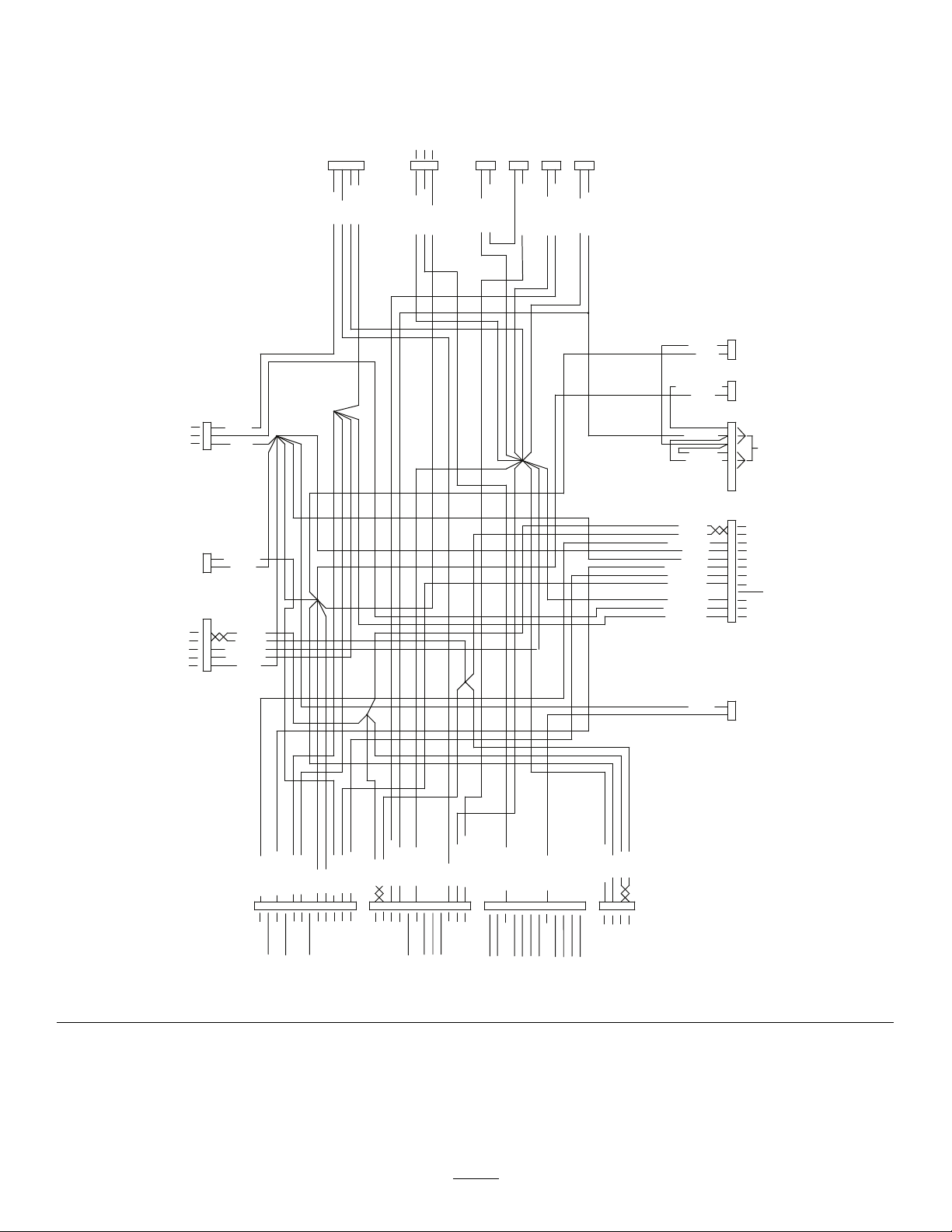
Schematics
BLACK
BLACK
BLACK
BLACK
BLACK
BLACK
RED/WHITE
BLUE
RED/WHITE
RED/WHITE
RED/WHITE
RED/GREEN
RED/WHITE
RED/WHITE
RED/WHITE
RED/WHITE
GREEN/YELLOW
GREEN/YELLOW
GREEN/BROWN
GREEN
YELLOW
BLUE/BLACK
GRAY/VIOLET
VIOLET/WHITE
VIOLET/RED
GREEN
RED/GREEN
RED/WHITE
GREEN
YELLOW
YELLOW
BLACK
ORANGE
YELLOW
GREEN
ORANGE
WHITE /GREEN
ORANGE
BLACK
BLACK
BLUE/BLACK
GREEN/BROWN
GREEN/YELLOW
VIOLET/WHITE
BLUE
ORANGE
GRAY/VIOLET
VIOLET/RED
ACC
CLUTCH
SERVICE
CONNECTOR
MCU GRAY
CONNECTOR
MCU BLACK
CONNECTOR
MCU GREEN
CONNECTOR
LDU
LIFT/LOWER
SWITCH
RAISE S2
TO CONNECTOR
P07 ON HARNESS
LOWER S1
KEY
SWITCH
PTO SWITCH
LH
NEUTRAL
RH
NEUTRAL
BRAKE
SWITCH
SEAT
SWITCH
CAN LOW
CAN HIGH
START
SW
PWR
GND
PWR
OUT
B+
ALARM
B+
GND
GND
START
KEY A
BRAKE
CAN HI
KEY S
CAN LOW
NEUTRAL
OPC
PTO SWITCH
TRANS TEMP
CAN HI
PWR
GND
CAN LOW
PWR
GND
CAN LOW
SW
PWR
CAN HI
ACC PWR
GND
ACC SIGNAL
TRANSMISSION
TEMP SENSOR
BLACK
GRAY/RED
RED/WHITE
RED/GREEN
ORANGE/RED
GND
GND
FUSED
PWR
ACC
PWR
BLACK
BLACK
CLUTCH
ALARM
FUEL PUMP
PWR
FUEL PUMP
PWR
RED/GREEN
RED-GREEN
RED-GREEN
RED-GREEN
PWR TO RUN
PWR TO RUN RED/GREEN
RED/GREEN
PWR
RAISE = PWR to S1 + S2
LOWER= PWR to S1
RED/WHITE
GREEN/GRAY
GREEN/GRAY
WHITE/GRAY
CONFIG
START= B, C, D
OFF= NONE
ACC= A, C, D
P01
121110
987654321
P02
2
11
10
9876543121
P03
121110
987654321
P13
1
2
P12
1
2
P11
1
2
P10
1
2
P17
A B
P04
432
1
1
SP3
1
SP2
1
SP1
1
SP4
1
SP5
1
SP6
P18
1 2 3 4 5 6
P16
A B C
P09
12
P08
12
P06
111071268359421
P07
12345678
P05
21
P14
ABC
1
SP7
P15
ABC
D
g229105
ElectricalSchematic—MachinewithHorizonDisplayMonitor(Rev.A)
65

ENGINE
GROUND
STARTER
B+
RED
RED
ORANGE
DPF
TO HARNESS B CONNECTOR 40
TO HARNESS B CONNECTOR 41TO HARNESS B CONNECTOR 42
TO HARNESS B
CONNECTOR 43
TO CONNECTOR P06 ON HARNESS
OIL
PRESSURE
SWITCH
BLACK
BLACK
BLACK
BLACK
BLACK
BLUE
RED
ORANGE
RED/WHITE
BLUE
WHITE
BROWN
GREEN
VIOLET
RED
RED
RED
VIOLET
BLUE
YELLOW
BLUE
RED
YELLOW
WHITE
BLACK
BROWN
VIOLET
WHITE
RED
GREEN
BROWN
RED
GREEN
BLACK
RED
BLUE
BLACK
VIOLET
ORANGE
BLACK
BLUE
BROWN
BLUE
YELLOW
YELLOW
ORANGE
WHITE
BLUE
BROWN
RED
YELLOW
VIOLET YELLOW
VIOLET
VIOLET
YELLOW
ORANGE
W099 TXL10BK
GREEN
BLACK
BLACK
BLACK
BLUE
GREEN
ORANGE
RED
GND
CAN LOW
SW PWR
BLUE
RED
RED
FUSED
PWR
RED/GREEN
ACC PWR
BLACK
BLACK
BLACK
REGEN
D-GND
EGR TEMP/TEGR
ANALOG GND/A_GND
PDPF
5VS
EXH TEMP/TEXMH
DPF INLET TEMP/TOPFI
DPF MIDDLE TEMP/TOPFM
UB2
UB5
START RELAY/STR_RLY(D_UB5)
GLOW RELAY/SAID_RLYVBVBVBCAN1H
CAN1L
CAN2H
CAN2L
5VS
P. EGR
P. EGR L.
ANALOG GND/A_GND
LOW OIL LAMP/LOPSW
NO REGEN SW.
TFAIR
ANALOG GND/A_GND
5VS
IVPS
ANALOG GND/A_GND
IGN SW.
5VS
ANALOG GND/A_GND
APS1
GND
GND
GND
ENGINE CONTROLLER
(94 PIN)
5VS
PRAIL
ANALOG GND
5VS
CMSPD
ANALOG GND
CKSPD
CKSPD
ANALOG GND
TF0
ANALOG GND
IVDCM-L
IVDCM-H
ANALOG GND
TW
UB2
INJ3-H
INJ3-L
INJ2-H
INJ2-L
INJ1-H
INJ1-L
MPROP-H
HPPSO-L
ENGINE
CONTROLLER
(60 PIN)
YANMAR
CAN
CHECKER
YELLOW
GREEN
YELLOW
BLUE
BLACK
ORANGE
DPF PRESSURE
SENSOR
INLET TEMP
MIDDLE TEMP
WHITE
UB5
PDPFH
DPF-M4
AIR TEMP
UB3
UB3
B+ @ BATTERY
CLAMP
RED
YELLOW
GREEN
WHITE
BLUE
BLUE
BLACK
FLYBACK
DIODE
REVERSE
POLARITY
PROTECTION
DIODE
GREEN
ENGINE ECU
CASE GROUND
BLACK
(CONNECT @ BATT NEG)
GND
FUEL PUMP
BLACK
BLACK
CAN HIGH
BLACK
RED/WHITE
RED
RED
RED
AIR
FILTER
SW
ALARM
12V
POWER
PORT
GRAY/BROWN
RED/WHITE
GRAY/VIOLET
BLACK
BLACK
RED
RED/GREEN
RED
POWER
PORT
FUSE 15A
POWER DISTRIBUTION
MODULE
ENGINE FUSE 25A
CHASSIS FUSE 15A
B
ALTERNATOR
IG
EGR RELAY
(30)
(86)
(87)
(87A)
(85)
STARTER
"S"
GLOW
PLUGS
START RELAY
GLOW
RELAY
(30)
(85)
(87)
(86)
ACL SW
ALARM
ACC
FUSE 15A
FUEL PUMP
RED
RED/GREEN
RED/GREEN
GRAY/VIOLET
RED
PWR TO RUN
(30)
(86)
(87)
(87A)
(85)
RELAY DIAGRAM
87a
87
86
85
30
STARTSW
CHGSW
COIL
J05
1
SP05
SP04
SP08
SP01
SP06
SP03
SP02
SP09
SP10
SP11
P11
AB
J04
1
P12
1234567891011
12
P20
1
P16
A B
P18
1 2 3 4 5
P17
1 2 3 4 5
P14
1 2
P03
CBA
J02
1
J01
1
P07
751264310118921
P06
21
P09
654321
P05
21
J03
1
P04
12
P10
CBA
P08
21
P24
1234567891011
12
P23
1 2 3 4 5 6 7 8 9 10 11 12
P22
12 11 10 9 8 7 6 5 4 3 2 1
P21
8 7 6 5 4 3 2 1
J06
1
P13
1 2
P15
1 2 3 4 5 6
P02
541633174718483012345960285029192051113854395237825267
P01
18653377632456818068357328
70
531
54767553458539741566317921232052884362
61
246
90
41
SP12
P19
1 2 3 5 6 7 8 9
ElectricalSchematic—YanmarEngine3TNV80FT(Rev.A)
66
g229107

ENGINE
GROUND
STARTER
B+
TO CONNECTOR
P06 ON HARNESS
GND
CAN LOW
SW PWR
START
FUSED PWR
ACC PWR
YANMAR
CAN CHECKER
BATTERY
CLAMP
B+
GND
FUEL
PUMP
CAN HIGH
ACTUATOR RELAY
30
8687
87A85
PREHEAT RELAY
30
8687
87A85
START RELAY
30
8687
87A85
FLY BACK
DIODE
OIL
PRESSURE
SW
STARTER
SIGNAL
GLOW
B
COOLANT
TEMP
SENSOR
RACK
ACT
ALTERNATOR
ENGINE
SPEED
SENSOR
CAN LOW
CAN HIGH
RED/GREEN
BLACK
BLACK
RED/WHITE
GREEN
BLACK
RED/GREEN
BLUE/GREEN
BLUE/GRAY
RED/GREEN
RED/GREEN
BLACK
BLUE/RED
BLACK
BLACK
BLACK
BLACK
BLUE/RED
YELLOW
BROWN
BLACK
BLACK
BLACK
WHITE
ORANGE
BLACK
ORANGE
BLACK
BLACK
RED/WHITE
BLUE/YELLOW
BLUE
BLACK
BLACK
BLACK
GRAY/WHITE
GREEN
YELLOW
YELLOW
GREEN
YELL
OW
RED/GREEN
IGN SW
ENGINE
CONT
ROLLER
(48 PIN)
START
SW
NRPW_GND
4A
RET
NRPW
APD_0P1
GNDA
RECAN
RACK_RLY
MAIN_RLY
RPS
CAN
LOW
CAN HIGH
RACK_SOL
AVB
AIR_HT_RLY
GND
VB
GND
IG
L
BLUE/RED
BLUE/YELLOW
BLACK
GND
PWR
BLACK
BLACK
BLACK
AIR
FILTER
SW
ALARM
12V
POWER
PORT
POWER PORT
FUSE 15A
POWER
DISTRIBUTION
MODULE
GRAY/BROWN
FUSE 10A
MAIN
FUSE 15A
CHASSIS
COIL
(5)
(2)
(3)
COMMON
N.O.
ALARM
YELLOW/VIOLET
BLACK
BLACK
BLACK
RED/YELLOW
YELLOW
ATM PRESSURE
SENSOR
APP_IP2
APP_IP5
4B4D4C4E4F4H4G4J4K
3A3B3D3C3E3F3H3G3J
3K
2A2B2D2C2E2F2H2G2J
2K
1A1B1D1C1E1F1H1G1J
1K
4L
4M
3M
3L
2L
2M
1M
1L
FUEL PUMP
15A ACC FUSE
RED/GREEN
RED/GREEN
RED/GREEN
RED/GREEN
RED/GREEN
RED/GREEN
RED/GREEN
RED/GREEN
RED
RED
RED
RED
RED
RED
RED/WHITE
PWR TO
RUN
OIL TEMP
SENSOR
GRAY/ORANGE
ORANGE
GREEN
GREENGREEN
P03
CBA
P20
1
P01
123456789
101112131415161718192021222324252627282930313233343536373839404142434445464748
P07
111071268359421
P16
A B
P06
21
P15
1 2 3 4 5
P14
3 2 4 5 1
J06
1
P18
1 2 3 4 5
J05
1
P09
654321
J01
1
J02
1
SP1
P05
21
J03
1
SP2
SP4
SP3
SP5
SP6SP7
P11
1 2
P13
2
1
P02
12345
6
SP8
SP9
SP10
P04
12
P10
CBA
P08
21
P12
123456789
101112
SP11
P21
2
1
P17
1 2 3
SP12
ElectricalSchematic—YanmarEngine3TNV88C(Rev.A)
g229106
67

CaliforniaProposition65WarningInformation
Whatisthiswarning?
Youmayseeaproductforsalethathasawarninglabellikethefollowing:
WARNING:CancerandReproductiveHarm—www.p65Warnings.ca.gov.
WhatisProp65?
Prop65appliestoanycompanyoperatinginCalifornia,sellingproductsinCalifornia,ormanufacturingproductsthatmaybesoldinorbroughtinto
California.ItmandatesthattheGovernorofCaliforniamaintainandpublishalistofchemicalsknowntocausecancer,birthdefects,and/orother
reproductiveharm.Thelist,whichisupdatedannually,includeshundredsofchemicalsfoundinmanyeverydayitems.ThepurposeofProp65isto
informthepublicaboutexposuretothesechemicals.
Prop65doesnotbanthesaleofproductscontainingthesechemicalsbutinsteadrequireswarningsonanyproduct,productpackaging,orliteraturewith
theproduct.Moreover,aProp65warningdoesnotmeanthataproductisinviolationofanyproductsafetystandardsorrequirements.Infact,the
CaliforniagovernmenthasclariedthataProp65warning“isnotthesameasaregulatorydecisionthataproductis‘safe’or‘unsafe.’”Manyofthese
chemicalshavebeenusedineverydayproductsforyearswithoutdocumentedharm.Formoreinformation,gotohttps://oag.ca.gov/prop65/faqs-view-all
AProp65warningmeansthatacompanyhaseither(1)evaluatedtheexposureandhasconcludedthatitexceedsthe“nosignicantrisklevel”;or(2)
haschosentoprovideawarningbasedonitsunderstandingaboutthepresenceofalistedchemicalwithoutattemptingtoevaluatetheexposure.
Doesthislawapplyeverywhere?
Prop65warningsarerequiredunderCalifornialawonly.ThesewarningsareseenthroughoutCaliforniainawiderangeofsettings,includingbutnot
limitedtorestaurants,grocerystores,hotels,schools,andhospitals,andonawidevarietyofproducts.Additionally ,someonlineandmailorder
retailersprovideProp65warningsontheirwebsitesorincatalogs.
.
HowdotheCaliforniawarningscomparetofederallimits?
Prop65standardsareoftenmorestringentthanfederalandinternationalstandards.TherearevarioussubstancesthatrequireaProp65warning
atlevelsthatarefarlowerthanfederalactionlimits.Forexample,theProp65standardforwarningsforleadis0.5μg/day,whichiswellbelow
thefederalandinternationalstandards.
Whydon’tallsimilarproductscarrythewarning?
•ProductssoldinCaliforniarequireProp65labellingwhilesimilarproductssoldelsewheredonot.
•AcompanyinvolvedinaProp65lawsuitreachingasettlementmayberequiredtouseProp65warningsforitsproducts,butothercompanies
makingsimilarproductsmayhavenosuchrequirement.
•TheenforcementofProp65isinconsistent.
•CompaniesmayelectnottoprovidewarningsbecausetheyconcludethattheyarenotrequiredtodosounderProp65;alackofwarningsfora
productdoesnotmeanthattheproductisfreeoflistedchemicalsatsimilarlevels.
WhydoesT oroincludethiswarning?
Torohaschosentoprovideconsumerswithasmuchinformationaspossiblesothattheycanmakeinformeddecisionsabouttheproductstheybuyand
use.T oroprovideswarningsincertaincasesbasedonitsknowledgeofthepresenceofoneormorelistedchemicalswithoutevaluatingthelevelof
exposure,asnotallthelistedchemicalsprovideexposurelimitrequirements.WhiletheexposurefromToroproductsmaybenegligibleorwellwithinthe
“nosignicantrisk”range,outofanabundanceofcaution,T orohaselectedtoprovidetheProp65warnings.Moreover,ifTorodoesnotprovidethese
warnings,itcouldbesuedbytheStateofCaliforniaorbyprivatepartiesseekingtoenforceProp65andsubjecttosubstantialpenalties.
RevA

FormNo.3444-446RevC
AufsitzrasenmäherderSerieZ
Master
®
Professional7500-D
Mit152cmoder183cmTURBOFORCE
Heckauswurfmähwerk
Modellnr.72028—Seriennr.408863644undhöher
Modellnr.72029—Seriennr.407600000undhöher
Modellnr.72065—Seriennr.408864664undhöher
Modellnr.72074—Seriennr.408961606undhöher
®
RegistrierenSieIhrProduktunterwww.Toro.com.
Originaldokuments(DE)
*3444-446*
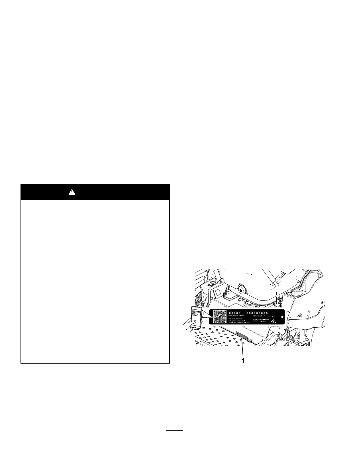
EntsprechenddemCaliforniaPublicResourceCode
Section4442oder4443istderEinsatzdesMotorsin
bewaldetenoderbewachsenenGebietenohnerichtig
gewartetenundfunktionsfähigenFunkenfänger,
wieinSection4442deniert,oderohneeinen
Motorverboten,dernichtfürdieBrandvermeidung
konstruiert,ausgerüstetundgewartetist.
DiebeiliegendeMotoranleitungenthältAngaben
zudenAbgasbestimmungenderamerikanischen
EnvironmentalProtectionAgency(EPA)undden
KontrollvorschriftenvonKalifornienzuAbgasanlagen,
derWartungundGarantie.SiekönneneinenErsatz
beimMotorherstelleranfordern.
Brutto-oderNettodrehmoment:DasBruttooderNettodrehmomentdiesesMotorswurdenvom
MotorherstellerimLaborgemäßSAEJ1940oder
J2723ermittelt.DertatsächlicheMotordrehmoment
beidieserKlassederMäheristbeieiner
KongurationzurEinhaltungderSicherheits-,
Emissions-undBetriebsanforderungenwesentlich
geringer.WeitereInformationenndenSieinder
MotorbedienungsanleitungdesHerstellers,diemit
derMaschineausgeliefertwurde.
WARNUNG:
KALIFORNIEN
WarnungzuProposition65
DieDieselauspuffgaseundeinige
BestandteilewirkenlautdenBehörden
desStaatesKalifornienkrebserregend,
verursachenGeburtsschädenoderandere
DefektedesReproduktionssystems
Batteriepole,-klemmenund-zubehör
enthaltenBleiundBleibestandteile.Dies
sindChemikalien,dielautdenBehörden
desStaatesKalifornienkrebserregend
sindundzuErbschädenführenkönnen.
WaschenSiesichnachdemUmgangmit
diesenMaterialiendieHände.
BeiVerwendungdiesesProduktssind
Sieggf.Chemikalienausgesetzt,
dielautdenBehördendesStaates
Kalifornienkrebserregendwirken,
GeburtsschädenoderandereDefektedes
Reproduktionssystemsverursachen.
Einführung
DieserAufsitzermitSichelmessernsolltevon
LandschaftsbauernundgeschultenLohnarbeitern
verwendetwerden.EristhauptsächlichfürdasMähen
vonGrasaufgepegtenGrünächeninPrivat-oder
öffentlichenAnlagengedacht.WenndieseMaschine
füreinenanderenZweckalsvorgeseheneingesetzt
wird,kanndasfürSieundanderePersonengefährlich
sein.
LesenSiedieseInformationensorgfältigdurch,
umsichmitdemordnungsgemäßenEinsatzund
derWartungdesGerätsvertrautzumachenund
VerletzungenundeineBeschädigungdesGerätszu
vermeiden.SietragendieVerantwortungfüreinen
ordnungsgemäßenundsicherenEinsatzdesGeräts.
BesuchenSieToro.com,hinsichtlichProduktsicherheit
undSchulungsunterlagen,Zubehörinformationen,
StandorteinesHändlersoderRegistrierungdes
Produkts.
WendenSiesichandenT oro-Vertragshändler
oderKundendienst,wennSieeineServiceleistung,
OriginalersatzteilevonT orooderweitere
Informationenbenötigen.HabenSiedafürdieModellundSeriennummernderMaschinegriffbereit.Bild1
zeigtdiePositionderModell-undSeriennummern
amProdukt.TragenSiehierbittedieModell-und
SeriennummerndesGerätsein.
Wichtig:ScannenSiemitIhremMobilgerät
denQR-Code(fallsvorhanden)aufdem
Seriennummernaufkleber,umaufGarantie-,
Ersatzteil-oderandereProduktinformationen
zuzugreifen.
©2021—TheToro®Company
8111LyndaleAvenueSouth
Bloomington,MN55420
1.TypenschildmitModell-undSeriennummer
2
g235670
Bild1
KontaktierenSieunsunterwww.Toro.com.
Druck:USA
AlleRechtevorbehalten

Modellnr.
Seriennr.
IndieserAnleitungwerdenzweiBegriffezur
HervorhebungvonInformationenverwendet.Wichtig
weistaufspezielletechnischeInformationenhin,und
HinweishebtallgemeineInformationenhervor,die
IhrebesondereBeachtungverdienen.
DiesesSicherheitswarnsymbol(Bild2)wirdsowohl
indiesemHandbuchalsauchanderMaschine
verwendet,umwichtigeSicherheitshinweisezu
kennzeichnen,diezurVermeidungvonUnfällen
befolgtwerdenmüssen.DiesesSymbolwirdmit
demSignalwortGefahr,WarnungoderVorsicht
dargestellt.
•Gefahr:bezeichneteineunmittelbardrohende
Gefahr.Wennsienichtgemiedenwird,sindT od
oderschwersteVerletzungendieFolge.
•Warnung:bezeichneteinemöglicherweise
drohendeGefahr.Wennsienichtgemiedenwird,
könnenT ododerschwersteVerletzungendie
Folgesein.
•Vorsicht:bezeichneteinemöglicherweise
drohendeGefahr.Wennsienichtgemiedenwird,
könnenleichteodergeringfügigeVerletzungen
dieFolgesein.
Bild2
Sicherheitswarnsymbol
Inhalt
Sicherheit..................................................................5
AllgemeineSicherheit.........................................5
Winkelanzeige...................................................6
Sicherheits-undBedienungsschilder.................7
Produktübersicht.....................................................14
Bedienelemente..............................................15
Horizon-Anzeige...........................................15
TechnischeDaten............................................17
Anbaugeräte,Zubehör.....................................17
VordemEinsatz..................................................18
VordersicherenVerwendung...........................18
Betanken..........................................................19
DurchführentäglicherWartungsarbei-
ten.................................................................20
EinfahreneinerneuenMaschine......................20
VerwendendesÜberrollschutzes.....................20
VerwendungderSicherheitsschalter................21
EinstellendesSitzes.........................................22
EntriegelndesSitzes........................................22
ÄndernderSitzfederung...................................23
WährenddesEinsatzes.......................................23
HinweisezurSicherheitwährenddes
Betriebs.........................................................23
BetätigenderFeststellbremse..........................26
EinsetzendesZapfwellenantriebsschal-
ters................................................................26
AnlassendesMotors........................................27
AbstellendesMotors........................................27
VerwendenderFahrantriebshebel....................28
FahrenmitderMaschine..................................28
EinstellenderSchnitthöhe................................29
EinstellenderAntiskalpierrollen........................30
sa-black
EinstellendesUnterfahrschutzes.....................31
EinsatzmitdemÜberhitzungssensor................31
Betriebshinweise.............................................32
NachdemEinsatz...............................................33
HinweisezurSicherheitnachdem
Betrieb..........................................................33
VerwendenderAblassventiledes
Antriebsrads..................................................33
TransportierenderMaschine............................33
Wartung..................................................................36
SicherheitbeiWartungsarbeiten.......................36
EmpfohlenerWartungsplan.................................36
Schmierung.........................................................38
EinfettenderMaschine.....................................38
SchmierenderJochgelenkedesAntriebs
undderKeilnut-Gleitverbindung....................38
EinfettenderLaufradschwenkarme..................39
EinfettenderLaufradnaben..............................39
WartendesMotors..............................................40
SicherheitshinweisezumMotor........................40
WartendesLuftlters........................................40
WartendesMotoröls.........................................42
PrüfendesAbstandsdesMotorventils..............43
WartenderKraftstoffanlage.................................44
3

EntleerendesKraftstofflter/Wasserabschei-
ders...............................................................44
ErsetzendesWasserabscheiders....................45
PrüfenderKraftstofeitungundder
-anschlüsse...................................................45
WartenderelektrischenAnlage...........................45
HinweisezurSicherheitderElektroan-
lage...............................................................45
WartenderBatterie...........................................45
WartenderSicherungen...................................47
WartendesAntriebssystems...............................48
PrüfendesSicherheitsgurtes............................48
EinstellenderSpurweite...................................48
PrüfendesReifendrucks..................................49
PrüfenSiedieRadmuttern................................49
AnpassungdesLaufradschwenkarm-
Lagers...........................................................50
WartendesGetriebes.......................................50
WartenderKühlanlage........................................51
HinweisezurSicherheitdesKühlsy-
stems............................................................51
PrüfendesMotorkühlmittelstands.....................51
ReinigendesKühlers........................................52
WechselndesKühlmittels.................................52
WartenderBremsen...........................................53
EinstellenderFeststellbremse..........................53
WartenderRiemen.............................................55
PrüfenderRiemen...........................................55
AustauschendesMähwerk-Treibrie-
mens.............................................................55
PrüfenderSpannungdesLichtmaschinen-
riemens.........................................................56
WartenderBedienelementanlage.......................56
AnpassenderStellungdesSteuerhe-
bels...............................................................56
EinstellendesFahrsteuergestänges.................57
EinstellendesFahrantriebsstoßdämp-
fers................................................................58
WartenderHydraulikanlage................................59
SicherheitderHydraulikanlage.........................59
WartenderHydraulikanlage.............................59
WartendesMähwerks..........................................61
SicherheitshinweisezumMesser......................61
WartenderSchnittmesser................................61
NivellierendesMähwerks.................................64
Reinigung............................................................67
ReinigendesMotorraumsunddenBereich
derAuspuffanlage.........................................67
ReinigenderMaschineunddes
Mähwerks.....................................................67
BeseitigungvonAbfällen..................................67
Einlagerung............................................................68
SicherheitbeiderEinlagerung..........................68
ReinigungundEinlagerung..............................68
Fehlersucheund-behebung...................................70
Schaltbilder.............................................................73
4

Sicherheit
DieseMaschineerfülltENISO5395.
AllgemeineSicherheit
DiesesProduktkannHändeundFüßeamputieren
undGegenständeaufschleudern.BefolgenSiezum
VermeidenvonschwerenodertödlichenVerletzungen
immeralleSicherheitshinweise.
•LesenundverstehenSievordemAnlassendes
MotorsdenInhaltdieserBedienungsanleitung.
•HaltenSieUnbeteiligteundKinderfern.
•KinderodernichtgeschultePersonendürfendie
Maschinewederverwendennochwarten.Lassen
SienurPersonenzu,dieverantwortungsbewusst,
geschult,mitdenAnweisungenvertraut,und
körperlichinderLagesind,dieMaschinezu
bedienenundzuwarten.
•StellenSiedenÜberrollbügelimmerganzaufund
arretierenihn.LegenSiedenSicherheitsgurtan.
•SetzenSiedieMaschinenichtinderNähevon
Abhängen,Gräben,Böschungen,Gewässernoder
anderenGefahrenstellensowieanHanglagenmit
einemGefällevonmehrals15°ein.
•HaltenSieHändeundFüßevonbeweglichen
Teilenfern.
•BedienenSiedieMaschineniemals,wennnicht
alleSchutzvorrichtungen,Sicherheitsschalterund
Abdeckungenangebrachtundfunktionstüchtig
sind.
•StellenSievordemVerlassenderBedienerposition
denMotorab,ziehendenSchlüsselab,und
warten,bisallebeweglichenTeilezumStillstand
gekommensind.LassenSiedieMaschine
abkühlen,bevorSiesiewarten,einstellen,
betanken,reinigen,odereinlagern.
5

Winkelanzeige
Bild3
SiedürfendieseSeitefürdenpersönlichenGebrauchkopieren.
1.DasmaximaleGefälle,andemSiedieMaschineeinsetzenkönnen,beträgt15Grad.ErmittelnSiemitderGefälletabelledas
GefällederHängevordemEinsatz.SetzenSiedieseMaschinenichtaufHängenein,dieeinGefällevonmehrals15Grad
aufweisen.FaltenSieentlangderentsprechendenLinie,umdemempfohlenenGefällezuentsprechen.
2.FluchtenSiedieseKantemiteinervertikalenOberächeaus(Baum,Gebäude,Zaunpfahl,Pfostenusw.).
3.Beispiel,wieSieGefällemitdergefaltetenKantevergleichen
6
g011841

Sicherheits-undBedienungsschilder
DieSicherheits-undAnweisungsaufklebersindgutsichtbar;siebendensichinderNähe
dermöglichenGefahrenbereiche.TauschenSiebeschädigteoderverlorengegangene
Aufkleberaus.
decalbatterysymbols
Akkusymbole
DerAkkuweisteinigeoderallederfolgendenSymboleauf.
1.Explosionsgefahr
2.VermeidenSieFeuer,offenesLichtundrauchenSienicht
3.Verätzungsgefahr/VerbrennungsgefahrdurchChemikalien
4.TragenSieeineSchutzbrille.
5.LesenSiedieBedienungsanleitung.
6.UnbeteiligtePersonendürfensichnichtinderNähedes
Akkusaufhalten.
7.TragenSieeineSchutzbrille;explosiveGasekönnen
BlindheitundandereVerletzungenverursachen.
8.DieSäureimAkkukannschwerechemische
VerbrennungenundBlindheitverursachen.
9.SpülenSiedieAugensofortmitWasserundgehenSie
sofortzumArzt.
10.Bleihaltig:Nichtwegwerfen
93-6687
1.TretenSienichtaufdieseStelle.
99-8936
1.Maschinengeschwindigkeit4.Neutral
2.Schnell
3.Langsam
decal93-6687
decal99-8936
5.Rückwärts
Herstellermarke
1.Gibtan,dassdasMesserT eilderOriginalmaschinedes
Herstellersist.
58-6520
1.Fett
decaloemmarkt
decal106-5517
106-5517
1.Warnung:BerührenSienichtdieheißeOberäche.
decal58-6520
7

107-3069
1.Warnung:EsbestehtkeinÜberrollschutz,wennder
Überrollbügelabgesenktist.
2.LassenSiedenÜberrollbügelaufgestelltundarretiertund
legenSiedenSicherheitsgurtan,umschwereodertödliche
VerletzungenaufgrundeinesÜberschlagenszuvermeiden.
SenkenSiedenÜberrollbügelnurab,wennesunbedingt
erforderlichist.LegenSiekeinenSicherheitsgurtan,wenn
derÜberrollbügelabgesenktist.
3.LesenSiedieBedienungsanleitung.FahrenSielangsam
undvorsichtig.
decal109-6036
109-6036
NurMaschinenmitHeckauswurf
1.LesenSiedieBedienungsanleitung.
2.ZiehenSievordemDurchführenvonWartungs-oder
ReparaturarbeitendenSchlüsselabundlesenSiedie
Anweisungen.
3.Schnitthöhe
decal107-3069
decal112-9028
112-9028
1.Warnung:BerührenSiekeinebeweglichenT eileund
nehmenSiekeineSchutzblecheundSchutzvorrichtungen
ab.
decal116-5988
116-5988
1.Feststellbremse:
Eingekuppelt
2.Feststellbremse:
Ausgekuppelt
8

116-8283
1.Warnung:LesenSieinderBedienungsanleitungnach,wie
SiedieSchnittmesserschraube/-mutterbisauf75-81Nm
anziehen.
117-3276
decal116-8283
decal117-3276
1.Motorkühlmittelunter
Druck
2.Explosionsgefahr:
LesenSiedie
Bedienungsanleitung.
3.Warnung:BerührenSie
nichtdieheißeOberäche.
4.Warnung:LesenSiedie
Bedienungsanleitung.
9

126-8383
Hinweis:DieseMaschineerfülltdiedemIndustriestandardentsprechendenStabilitätstestsderstatischenStandfestigkeitin
Längs-undQuerrichtungmitderaufdemAufkleberangebrachtenempfohlenenMaximalneigung.LesenSiedieAnweisungeninder
BedienungsanleitungfürdenBetriebderMaschineanHanglagenunddieBedingungen,unterdenendieMaschineeingesetztwird,um
zuermitteln,obdieMaschineunterdenBedingungenandiesemTagundandiesemOrtverwendetwerdenkann.Veränderungenim
GeländekönnenzueinerVeränderunginderNeigungfürdenBetriebderMaschineführen.
decal126-8383
1.Warnung:LesenSiedieBedienungsanleitung;setzenSie
dieseMaschinenurnachentsprechenderSchulungeinund
trageneinenGehörschutz.
2.Schnitt-bzw.AmputationsgefahrfürHändebeim
SchnittmesserundVerhedderungsgefahrfürHändeam
Riemen:HaltenSiesichvonbeweglichenTeilenfernund
nehmenSiekeineSchutzvorrichtungenab.
3.GefahrbeiVerwendungderRampe:VerwendenSiebeim
VerladenaufeinenAnhängernichtzweiRampensondern
nureineRampe,diefürdieMaschinebreitgenugistund
eineNeigungvonwenigerals15Gradhat;fahrenSiebeim
VerladenrückwärtsaufdieRampeundfahrenSiebeim
EntladenvorwärtsvonderRampe.
4.GefahrdurchÜberfahren:NehmenSiekeinePassagiere
mit;schauenSienachhinten,wennSieimRückwärtsgang
mähen.
5.GefahrdurchherausgeschleuderteObjekte:Unbeteiligte
müsseneinenAbstandzurMaschinehalten.
6.Kippgefahr:verwendenSiedieMaschinenichtinderNähe
vonAbhängenoderanSteigungenüber15°.FahrenSienur
aufSteigungenunter15°.
decal126-9275
126-9275
10

decal126-9278
126-9278
1.Motor:Aus
4.DrückenSiedieUnterseitederT aste,umdasMähwerk
abzusenken.
2.Motor:Ein
5.DrückenSieaufdieOberseitederTaste,umdasMähwerk
anzuheben.
3.Motor:Anlassen
126-9279
1.LesenSiedieAnweisungen,bevorSieService-oder
WartungsarbeitenanderMaschinedurchführen.
2.Zeitintervall
3.PrüfenSiedenÖlstandimMotor.
4.PrüfenSiedenKühlmittelstand;weitereAnweisungennden
SieinderBetriebsanleitung.
5.PrüfenSiedenReifendruck(anzweiStellen).11.SchmierenSiedieRadlagerdervorderenLaufräder(an
6.PrüfenSiedenHydraulikölstand;weitereAnweisungennden
SieinderBetriebsanleitung.
7.PrüfenSiedenHydraulikölstandderZwischenwelle.
8.SchmierenSiedieZapfwelledesMähwerkantriebs;weitere
AnweisungenndenSieinderBetriebsanleitung.
9.PrüfenSiedenLuftlter.
10.SchmierenSiedasSpannscheibengelenk;weitere
AnweisungenndenSieinderBetriebsanleitung.
zweiStellen);weitereAnweisungenndenSieinder
Betriebsanleitung.
12.SchmierenSiedievorderenLaufradgelenke(anzweiStellen);
weitereAnweisungenndenSieinderBetriebsanleitung.
decal126-9279
11

decal135-0328
135-0328
126-9280
FürModellemit152cmoder183cmMähwerkemit
Heckauswurf
1.Riemenführung
126-9351
1.Fahrgestell(15A)3.Haupt(25A)
2.Zubehör(15A)4.Steckdose(15A)
decal126-9280
decal126-9351
1.ZiehenSiedieRadmuttern
aufeinDrehmomentvon
129Nman.
2.LesenundverstehenSie
vordemDurchführen
vonWartungsarbeitendie
Betriebsanleitung.Prüfen
SiedasDrehmoment
nachdenersten100
Betriebsstundenunddann
alle500Betriebsstunden.
1.LesenSiedie
Bedienungsanleitung.
2.Schnitthöhe
127-0326
3.ZiehenSievordem
Durchführenvon
Wartungsarbeiten
denZündschlüssel
abundlesenSiedie
Bedienungsanleitung.
decal127-0326
1.Gefahrdurch
herausgeschleuderte
Objekte:Unbeteiligte
müsseneinenAbstandzur
Maschinehalten.
decal135-0664
135-0664
2.Schnitt-bzw.
Verletzungsgefahrfür
HändeundFüße:
HaltenSiesichvon
beweglichenTeilenfern
undnehmenSiekeine
Schutzvorrichtungenoder
Schutzblecheab.
12
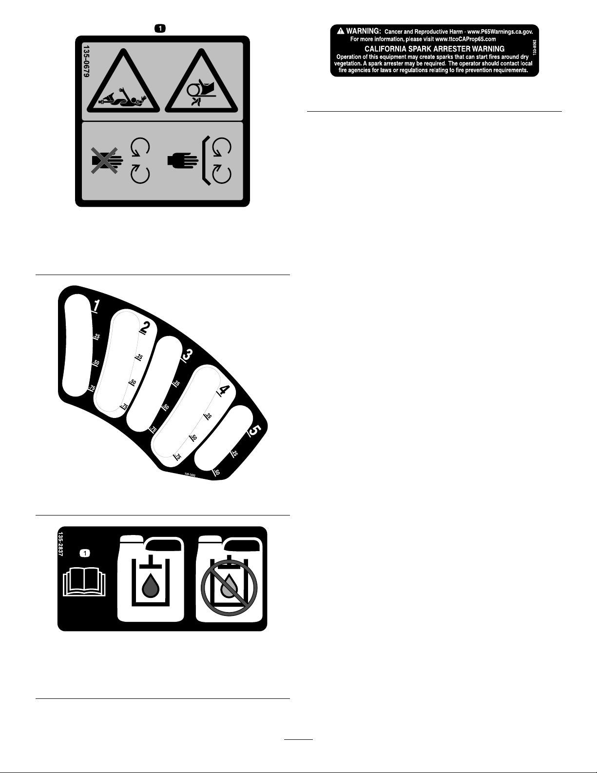
135-0679
1.EinzugsgefahramRiemen/sichdrehenderAntriebsstrang;
HaltenSieeinenAbstandzubeweglichenTeilenundlassen
SiealleSchutzvorrichtungenundSchutzblechemontiert.
decal133-8062
133-8062
decal135-0679
decal135-1432
135-1432
decal135-2837
135-2837
1.WeitereInformationenndenSieinderBetriebsanleitung;
VerwendenSierotesToroGetriebeölfürNasskupplungen;
verwendenSiekeingrünesHydrauliköl.
13

Produktübersicht
1.Schnitthöhen-Einstellstift
2.Feststellbremshebel8.Tankdeckel
3.Monitor/Bedienelemente
4.Überrollbügel
5.Motorgitter
6.AkustischerAlarmundStromanschluss
g227303
Bild4
7.Fahrantriebshebel
9.Antiskalpierrolle
10.Unterfahrschutz
11.Laufrad
12.Mähwerk
14
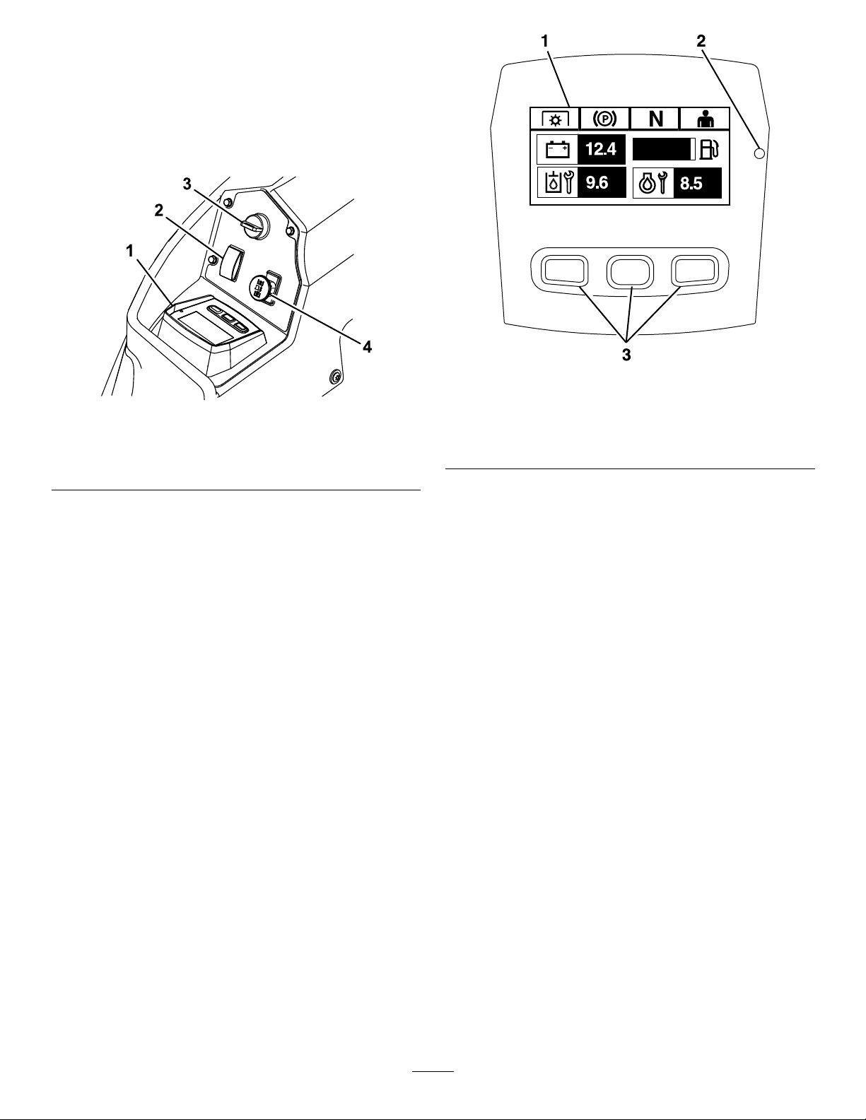
Bedienelemente
MachenSiesichvordemStartdesMotorsundder
VerwendungderMaschinemitallenBedienelementen
vertraut.
Bedienfeld
Bild5
1.Horizon-Anzeige3.Zündschloss
2.Mähwerkhubschalter
4.Zapfwellenantriebsschalter
g228164
Bild6
g225792
1.Sieb
2.LED-Statusleuchte
Horizon-Anzeige
3.Tasten
Horizon-Anzeige
AusführlicheInformationenüberdieBedienerschnittstelle,mitderSieaufInformationenzugreifen,Zähler
zurücksetzen,Systemeinstellungenändernund
StörungenamGerätbehebenkönnen,ndenSiein
derSoftwareanleitung.
Informationsbildschirm
DerInformationsbildschirmzeigtInformationenzum
BetriebderMaschinean;weitereInformationennden
SieinderSoftwareanleitung.
Tasten
DieMultifunktionstastenbendensichim
unterenBereichdesBedienfelds.Dieaufdem
InformationsbildschirmoberhalbderTasten
angezeigtenSymbolezeigendieaktuelleFunktionan.
MitdenTastenkönnenSiedieMotordrehzahlwählen
unddurchdieSystemmenüsnavigieren.
WeitereInformationenndenSieinder
Softwareanleitung.
LED-Statusleuchte
DieLED-StatusleuchteistzurAnzeigedes
Systemstatusmehrfarbigundbendetsichaufder
rechtenSeitedesBedienfelds.WährenddesStarts
leuchtetdieLEDrot,dannorangebisgrün,umdie
Funktionsfähigkeitzuüberprüfen.
•Grün:zeigtdienormaleBetriebsaktivitätan
•Rotblinkend:zeigteinenaktivenFehleran
•Grünundorangeblinkend:zeigtan,dasseine
RückstellungderKupplungerforderlichist
WeitereInformationenndenSieinder
Softwareanleitung.
15

Alarm
WenneinFehlerauftritt,wirdeineFehlermeldung
angezeigt,dieLEDleuchtetrot,undeinAlarmton
ertöntwiefolgt:
•EinschnellerPieptonweistaufkritischeFehlerhin.
•EinlangsamerPieptonweistaufwenigerkritische
Fehlerhin,wieetwaerforderlicheWartungs-oder
Serviceintervalle.
Hinweis:WährenddesStartsertöntderAlarm
kurz,umdieFunktionalitätzuüberprüfen.
WeitereInformationenndenSieinder
Softwareanleitung.
Betriebsstundenzähler
DerBetriebsstundenzählerzeichnetdieStunden
auf,diederMotorgelaufenist.Erläuft,wenn
derMotorläuft.RichtenSieIhreregelmäßigen
WartungsmaßnahmennachdieserAngabe(Bild5).
DieStundenwerdenaufdemBildschirmMotor-Aus
oderimMenüBetriebsstundenzählerMotor
angezeigt.
WeitereInformationenndenSieinder
Softwareanleitung.
WeitereInformationenndenSieinder
Softwareanleitung.
Zapfwellenantriebsschalter
MitdemZapfwellenantriebsschalterkuppelnSiedie
Schnittmessereinoderaus(Bild5).
DieLCD-AnzeigewirdaufdemInformationsbildschirm
eingeblendet,wennderZapfwellenschalter
ausgeschaltetist.
Hinweis:Maschinen,diemitdemHorizon-Monitor
ausgestattetsind,verfügenübereinen
Kupplungsschutz,deresermöglicht,die
Motordrehzahlautomatischzureduzieren,wennSie
denZapfwellenschalterausschalten.DurchEinundAusschaltendesZapfwellenschalterswirddie
MotordrosselzwischendenBetriebszuständenMÄHEN
undTRANSPORTumgeschaltet.
Hinweis:DasSystemermöglichtesIhnen,die
MaschinebeieingeschaltetemZapfwellenschalterzu
starten,dieMesserwerdenjedochnichteingekuppelt.
ZumEinschaltenderZapfwellemüssenSieden
Zapfwellenschalterzurücksetzen,indemSieihnausunddannwiedereinschalten.
Zündschloss
MitdemZündschlosslassenSiedenMotoran.Eshat
dreiStellungen:START,LAUFundAUS.
Hinweis:DieLCD-Anzeigenwerdeneingeblendet,
wennjedesBedienelementdenZustand„Sicherer
Start“erfüllt(z.B.dieAnzeigeleuchtetauf,wennSie
sichaufdemSitzbenden)
Hinweis:DasMotorsteuergerätsteuert
dieGlühkerzenbeimKaltstart.Wenndie
Kühlmitteltemperaturzuniedrigist,wirdaufdem
MonitordasGlühkerzensymbolangezeigtundder
Anlasserstartetnicht,wennSiedasZündschlossin
dieSTART-Stellungdrehen.DieGlühkerzenaktivieren
sichinderEIN-oderSTART-Stellung.Sobalddie
GlühkerzendieerforderlicheTemperaturerreicht
haben,verschwindetdasGlühkerzensymbolauf
demMonitorundderMotorstartet,wennSiedas
ZündschlossindieSTART-Stellungdrehen.
Hinweis:DasSystemermöglichtesIhnen,die
MaschinebeieingeschaltetemZapfwellenschalterzu
starten,dieMesserwerdenjedochnichteingekuppelt.
SiemüssendieZapfwelleausschalten,umdie
einkuppelnzukönnen.
Gasbedienung
DieGasbedienungsteuertdieMotordrehzahl,es
gibtdreiGeschwindigkeiten:Maximal,Efzientund
Niedrig.
Mähwerkhubschalter
DrückenSiedenSchalternachhinten,umdas
Mähwerkanzuheben.
DrückenSiedenSchalternachvorne,umdas
Mähwerkabzusenken.
Fahrantriebshebel
MitdenFahrantriebshebelnfahrenSiedieMaschine
vorwärts,rückwärtsundwenden(Bild4).
ArretierteNeutral-Stellung
SchiebenSiedieFahrantriebshebelvonderMitte
nachaußenindieARRETIERTENEUTRAL-Stellung,
wennSievonderMaschineabsteigen(Bild22).
StellenSiedieFahrantriebshebelimmerindie
ARRETIERTENEUTRAL-Stellung,wennSiedieMaschine
anhaltenoderunbeaufsichtigtlassen.
Feststellbremshebel
WennSiedenMotorabstellen,aktivierenSiedie
Feststellbremse,sodasssichdieMaschinenichtaus
Versehenbewegt.
16

TechnischeDaten
Anbaugeräte,Zubehör
Gesamtbreite
152cmMähwerk183cmMähwerk
168,2cm198,7cm
Gesamtlänge
Überrollbügelauf-oder
heruntergeklappt
Gesamthöhe
Überrollbügel,hochgeklappt
Überrollbügel,zusammengeklappt
Gesamthöhe
Überrollbügel,hochgeklappt
Überrollbügel,zusammengeklappt
LaufächenbreitederAntriebsräder
255,5cm
182,4cm
129,5cm
182,4cm
129,5cm
EinSortimentanvonT orozugelassenen
AnbaugerätenundZubehörwirdfürdieseMaschine
angeboten,umdenFunktionsumfangdesGerätszu
erhöhenundzuerweitern.WendenSiesichaneinen
ofziellenToro-VertragshändlerodernavigierenSie
aufwww.Toro.comfüreineListederzugelassenen
AnbaugeräteunddesZubehörs.
VerwendenSienurOriginalersatzteileund
-zubehörteilevonToro,umdieoptimaleLeistungund
Sicherheitzugewährleisten.ErsatzteileundZubehör
andererHerstellerkönnengefährlichseinundeine
VerwendungkönntedieGarantieungültigmachen.
112cm
LaufächenbreitederLaufräder
(MittenabstandderReifen):
152cmMähwerk183cmMähwerk
84cm84cm
Radstand(VonderMittedesLaufradreifens
zurMittedesAntriebsreifens)
152cmMähwerk183cmMähwerk
157,2cm157,2cm
17

Betrieb
Hinweis:BestimmenSiedielinkeundrechteSeite
derMaschineanhandderüblichenEinsatzposition.
VordemEinsatz
Vordersicheren
Verwendung
AllgemeineSicherheit
•KinderodernichtgeschultePersonendürfendie
Maschinewederverwendennochwarten.Örtliche
Vorschriftenschränkenu.U.dasMindestaltervon
Bedienernein.DerBesitzeristfürdieSchulung
allerBedienerundMechanikerverantwortlich.
•PrüfenSiedenArbeitsbereichderMaschine
undentfernenSiealleObjekte,diesichaufden
EinsatzderMaschineauswirkenodervonihr
aufgeschleudertwerdenkönnten.
•MachenSiesichmitdemsicherenBetriebder
MaschinesowiedenBedienelementenund
Sicherheitssymbolenvertraut.
•PrüfenSie,oballeSitzkontaktschalter,
Sicherheitsschalter,undSchutzvorrichtungen
montiertundfunktionsfähigsind.VerwendenSie
dieMaschinenur,wennsierichtigfunktioniert.
•StellenSievordemVerlassenderBedienerposition
denMotorab,ziehendenSchlüsselab,und
warten,bisallebeweglichenTeilezumStillstand
gekommensind.LassenSiedieMaschine
abkühlen,bevorSiesiewarten,einstellen,
betanken,reinigen,odereinlagern.
•ÜberprüfenSievordemMähendieMaschine
undstellenSiesicher,dassdieSchneideinheiten
ordnungsgemäßfunktionieren.
•BeurteilenSiedasGelände,umfestzulegen,
welcheAnbaugeräteundZubehörerforderlich
sind,umdieMaschineordnungsgemäßundsicher
bedienenzukönnen.
•TragenSiegeeigneteKleidung,u.a.eine
Schutzbrille,langeHosen,rutschfeste
ArbeitsschuheundeinenGehörschutz.Binden
SielangeHaarehintenzusammenundtragenSie
keinenSchmuckoderweiteKleidung.
•NehmenSienieMitfahreraufderMaschinemit.
•HaltenSieUnbeteiligteundHaustierewährend
derVerwendungderMaschinefern.SchaltenSie
dieMaschineunddas/dieAnbaugerät(e)ab,wenn
jemanddenBereichbetritt.
•BetreibenSiedieMaschinenur,wennalleSchutz-
vorrichtungenundSicherheitseinrichtungen,wie
z.B.dieAblenkbleche,vorhandensindund
ordnungsgemäßfunktionieren.ErsetzenSie
verschlisseneoderbeschädigteTeile,wennnötig.
Kraftstoffsicherheit
•Kraftstoffistextremleichtentammbar
undhochexplosiv.FeuerundExplosionen
durchKraftstoffkönnenVerbrennungenund
Sachschädenverursachen.
–StellenSiedenKanisterbzw.dieMaschine
vordemAuftankenaufdenBodenundnicht
aufeinFahrzeugoderaufeinObjekt,umeine
elektrischeLadungdurchdasEntzündendes
Kraftstoffszuvermeiden.
–FüllenSiedenKraftstofftankimFreienauf
ebenerFlächeauf,wennderMotorkaltist.
WischenSieverschüttetenKraftstoffauf.
–RauchenSienichtbeimUmgangmitKraftstoff,
undgehenSienichtinderNähevonoffenem
FeueroderFunkenmitKraftstoffum.
–EntfernenSieniedenTankdeckeloderfüllen
Kraftstoffein,wennderMotorläuftodernoch
heißist.
–WennSieKraftstoffverschütten,versuchen
Sienicht,denMotorzustarten.Vermeiden
Siees,Zündquellenzuschaffen,bisdie
Kraftstoffdämpfeverdunstetsind.
–BewahrenSieKraftstoffinvorschriftsmäßigen
KanisternfürKinderunzugänglichauf.
•KraftstoffistbeiEinnahmegesundheitsschädlich
odertödlich.WenneinePersonlangfristig
Benzindämpfenausgesetztist,kanndieszu
schwerenVerletzungenundKrankheitenführen.
–VermeidenSiedaslangfristigeEinatmenvon
Benzindämpfen.
–HaltenSieIhrGesichtundIhreHändevom
EinfüllstutzenundderÖffnungimKraftstofftank
fern.
–HaltenSieBenzinvonAugenundderHaut
fern.
•LagernSiewederdieMaschinenochden
KraftstoffkanisterinderNähevonoffenen
Flammen,FunkenoderZündammenwiez.B.bei
einemHeizkesselodersonstigenGeräten.
•FüllenSieKanisternieimFahrzeugoderauf
derLadepritscheeinesPritschenwagensoder
AnhängersmiteinerVerkleidungausKunststoff.
StellenSiedieBenzinkanistervordemAuffüllen
immervomFahrzeugentferntaufdenBoden.
•NehmenSiedasGerätvomPritschenwagenbzw.
AnhängerundbetankenesaufdemBoden.Falls
dasnichtmöglichist,betankenSiesolcheGeräte
miteinemtragbarenKanisterundnichtaneiner
Zapfsäule.
18

•SetzenSiedieMaschinenichtohnevollständig
montierteundbetriebsbereiteAuspuffanlageein.
•DerStutzensolltedenRanddesBenzinkanisters
oderdieBehälteröffnungbeimAuftanken
ständigberühren.VerwendenSienichtein
Mundstück-Öffnungsgerät.
•WechselnSiesofortIhreKleidung,wennKraftstoff
daraufverschüttetwird.
•FüllenSiedenT anknichtzuvoll.T auschenSie
denTankdeckelausundziehenihnfest.
•DieZusammensetzungdesgemischten
KraftstoffessollteASTMD975oderEN590
erfüllen.
•Biodieselmischungenkönnenlackierte
Oberächenbeschädigen.
•VerwendenSieB5(Biodieselgehaltvon5%)oder
einegeringereMischunginkaltemWetter.
•PrüfenSieDichtungenundSchläuche,diemit
KraftstoffinKontaktkommen,dasiesichnach
längererZeitabnutzenkönnen.
•EntfernenSieGrasundSchmutzvomMähwerk,
Auspuff,AntriebenunddemMotorraum,um
einemBrandvorzubeugen.WischenSieÖl-und
Kraftstoffverschüttungenauf.
Betanken
EmpfohlenerKraftstoff
DerMotorwirdmitsauberem,frischemDieselkraftstoff
miteinemCetanwertvonmindestens40betrieben.
BesorgenSie,umimmerfrischenKraftstoff
sicherzustellen,nursovielKraftstoff,wiesieinnerhalb
von30T agenverbrauchenkönnen.
VerwendenSiebeiT emperaturenüber-7°C
Sommerdiesel(Nr.2-D)undbeiTemperaturen
unter-7°CWinterdiesel(Nr.1-DoderNr.
1-D/2-D-Mischung).DerEinsatzvonWinterdiesel
beiniedrigerenTemperaturenvermitteltniedrigere
Flamm-undFließpunktmerkmale,wasdas
AnlassenverbessertunddieGefahreiner
chemischenTrennungdesKraftstoffes(wachsiges
Erscheinungsbild,Filterverstopfung)infolgeniedriger
Temperaturenverhindert.
•NachderUmstellungaufBiodieselmischungen
wirdderKraftstofflterfüreinigeZeitverstopfen.
•WeitereInformationenzuBiodieselmischungen
erhaltenSievomVertragshändler.
Betanken
1.StellenSiedieMaschineaufeinerebenen
Flächeab.
2.AktivierenSiedieFeststellbremse.
3.StellenSiedenMotorabundziehenSieden
Schlüsselab.
4.ReinigenSiedenBereichumdenTankdeckel.
5.FüllenSiedenKraftstofftankbiszurUnterseite
desFüllstutzens(Bild7).
Hinweis:FüllenSiedenKraftstofftanknicht
ganzauf.IndiesemfreienPlatzimTankkann
sichderKraftstoffausdehnen.
DieVerwendungvonSommerdieselüber-7°Cerhöht
dieLebensdauerderPumpenteile.
Wichtig:VerwendenSienieKerosinoderBenzin
anstellevonDieselkraftstoff.DasNichtbefolgen
dieserVorschriftführtzuMotorschäden.
Biodiesel-bereit
DieseMaschinekannauchmiteinemKraftstoff
eingesetztwerden,derbiszuB20mitBiodiesel
vermischtist(20%Biodiesel,80%Benzindiesel).
DerBenzindieselteilmusseinenextremniedrigen
Schwefelgehalthaben.
BefolgenSiedienachstehendenSicherheitsvorkehrungen:
•DerBiodieselanteildesKraftstoffsmussdie
SpezikationenASTMD6751oderEN14214
erfüllen.
19

Durchführentäglicher
Wartungsarbeiten
TäglichvordemStartderMaschinediefolgende
täglichePrüfroutinegemäßWartung(Seite36)
durchführen:
Einfahreneinerneuen
Maschine
NeueMotorenbrauchenetwasZeit,bevorsiedie
ganzeLeistungerbringen.NeueMähwerkeund
AntriebssystemehabeneinehöhereReibungund
belastendenMotormehr.DieEinfahrzeitfürneue
Maschinenbeträgtungefähr40bis50Stunden.
DanacherbringtderMotordieganzeLeistungund
bestePerformance.
Verwendendes
Überrollschutzes
Bild7
WARNUNG:
ZurVermeidungvonggf.tödlichen
VerletzungendurchÜberschlagenlassenSie
g027726
denÜberrollbügelinderhochgeklappten
undarretiertenStellungundlegenden
Sicherheitsgurtan.
StellenSiesicher,dassderSitzander
Maschinebefestigtist.
WARNUNG:
EsbestehtkeinÜberrollschutz,wennder
Überrollbügelabgesenktist.
•SenkenSiedenÜberrollbügelnurab,wenn
eswirklicherforderlichist.
•LegenSiebeiabgesenktemÜberrollbügel
keinenSicherheitsgurtan.
•FahrenSielangsamundvorsichtig.
•RichtenSiedenÜberrollbügelsofort
wiederauf,wenndieHöheeszulässt.
•AchtenSiesorgfältigaufdielichteHöhe
(wiez.B.zuÄsten,Pforten,Stromkabeln),
bevorSieunterirgendeinemHindernis
durchfahren,damitSiediesenicht
berühren.
20

AbsenkendesÜberrollbügels
Wichtig:SenkenSiedenÜberrollbügelnurab,
wenneswirklicherforderlichist.
1.WendenSieDruckaufdenoberenTeildes
Überrollbügelsan,umihnzusammenzuklappen.
2.ZiehenSiebeideHandräderherausunddrehen
sieum90°,damitsienichteingerastetsind(Bild
8).
3.SenkenSiedenÜberrollbügelab(Bild8).
Bild8
1.ObererT eildes
Überrollbügels
2.Handradinder
verriegeltenStellung
3.ZiehenSiedenKnopfzum
Entriegeln.
4.DrehenSiedenKnopfum
90°nachaußen,umihnin
derentriegeltenPosition
zuhalten.
5.Handradinder
entriegeltenStellung
g008619
Bild9
1.Eingekuppelt2.T eilweiseeingerastet:
dieMaschinedarfnicht
betriebenwerden,wenn
sichderÜberrollbügelin
dieserPositionbendet.
Verwendungder
Sicherheitsschalter
WARNUNG:
WenndieSicherheitsschalterabgeklemmt
oderbeschädigtwerden,könntesichdie
g225804
MaschineunerwartetinBetriebsetzenund
jemandenverletzen.
•AndenSicherheitsschalterndürfenkeine
Veränderungenvorgenommenwerden.
•PrüfenSiedieFunktionder
Sicherheitsschaltertäglichundtauschen
SiealledefektenSchaltervordemEinsatz
derMaschineaus.
HochklappendesÜberrollbügels
Wichtig:LegenSieimmerdenSicherheitsgurt
an,wennderÜberrollbügelaufgeklapptist.
1.HebenSiedenÜberrollbügelindie
BetriebsstellunganunddrehendieHandräder,
bissiesichteilweiseindenSchlitzenbewegen
(Bild9).
2.KlappenSiedenÜberrollbügelganzhoch
unddrückenSiegleichzeitigaufdenoberen
Überrollbügel,damitdieStifteeinrasten,wenn
dieLöchermitdenStiftenausgeuchtetsind
(Bild9).
3.DrückenSieaufdenÜberrollbügel,um
sicherzustellen,dassbeideStifteeinrasten(Bild
9).
FunktionderSicherheitsschalter
DieSicherheitsschalterverhinderndasAnlassendes
Motors,außerinfolgendenSituationen:
•DieFeststellbremseistaktiviert.
•DerZapfwellenantriebsschalteristausgekuppelt.
•DieFahrantriebshebelsindinderARRETIERTEN
NEUTRAL-Stellung.
DieSicherheitsschaltersindgleichfallsso
ausgelegt,dasssiedenMotorabstellen,wenndie
FahrantriebshebelbeiaktivierterFeststellbremseaus
derARRETIERTENNEUTRAL-Stellungbewegtwerden,
oderwennSiebeiaktiviertemZapfwellenantriebvom
Sitzaufstehen.
DerHorizon-MonitorhatAnzeigen,diedenBediener
daraufhinweisen,dassderSicherheitsschalterin
21

derrichtigenStellungist.DiekorrekteStellungder
KomponentewirdamBildschirmangezeigt.
5.SetzenSiesichaufdenSitz,lösendieFeststellbremse,stellendenZapfwellenantriebsschalter
indieAUS-StellungundschiebendieFahrantriebshebelindieARRETIERTENEUTRAL-Stellung.
VersuchenSie,denMotoranzulassen.Der
Motordarfnichtanspringen.
Bild10
1.DiekorrekteStellungderSicherheitsschalterwird
angezeigt.
TestenderSicherheitsschalter
Wartungsintervall:BeijederVerwendungoder
täglich
TestenSiedieSicherheitsschaltervorjedem
EinsatzderMaschine.LassenSie,wenn
dieSicherheitsschalternichtwienachstehend
beschriebenfunktionieren,dieseunverzüglichvon
einemVertragshändlerreparieren.
1.SetzenSiesichaufdenSitz,aktivieren
dieFeststellbremseundstellenden
ZapfwellenantriebsschalterindieEIN-Stellung.
VersuchenSie,denMotoranzulassen.Der
Motordarfnichtanspringen.
2.SetzenSiesichaufdenSitz,aktivieren
dieFeststellbremseundstellenden
ZapfwellenantriebsschalterindieAUS-Stellung.
SchiebenSieeinenderFahrantriebshebelaus
derARRETIERTENNEUTRAL-Stellung.Versuchen
Sie,denMotoranzulassen.DerMotordarfnicht
anspringen.WiederholenSiedieSchrittefür
denanderenFahrantriebshebel.
g230650
EinstellendesSitzes
DerSitzkannnachvorneundhintengeschoben
werden.StellenSiedenSitzsoein,dassSiedie
Maschineoptimalsteuernkönnenundkomfortabel
sitzen(Bild11).
g019754
Bild11
EntriegelndesSitzes
DrückenSiedenSitzriegelnachvorne,umdenSitz
zuentriegeln(Bild12).
3.SetzenSiesichaufdenSitz,aktivierendie
Feststellbremse,stellendenZapfwellenantriebsschalterindieAUS-Stellungundschieben
dieFahrantriebshebelindieARRETIERTE
NEUTRAL-Stellung.LassenSiedannden
Motoran.LösenSiebeilaufendemMotordie
Feststellbremse,aktivierendenZapfwellenantriebsschalterundstehenetwasvomSitzauf;
derMotorsollteabgestelltwerden.
4.SetzenSiesichaufdenSitz,aktivierendie
Feststellbremse,stellendenZapfwellenantriebsschalterindieAUS-Stellungundschieben
dieFahrantriebshebelindieARRETIERTE
NEUTRAL-Stellung.LassenSiedannden
Motoran.ZentrierenSiebeilaufendemMotor
einenderFahrantriebshebelundbewegenihn
(vorwärtsoderrückwärts);derMotormussdann
abstellen.WiederholenSiedasVerfahrenfür
denanderenFahrantriebshebel.
g008956
Bild12
1.Sitzverriegelung2.Sitz
22

ÄndernderSitzfederung
DerSitzkannzurOptimierungdesSitzkomforts
verstelltwerden.StellenSiedenSitzineinefürSie
bequemenStellung.
DrehenSiedasHandradzumVerstellenander
Vorderseitesolange,bisdergewünschteKomfort
erreichtist(Bild13).
Bild13
1.HandradfürdieSitzfederung
WährenddesEinsatzes
HinweisezurSicherheit
währenddesBetriebs
•SetzenSiedieMaschinenurbeiguten
Sichtverhältnissenundgeeigneten
Witterungsbedingungenein.FahrenSie
dieMaschineniebeiGewitter,bzw.wennGefahr
durchBlitzschlagbesteht.
•BerührenSiedieSchneideinheitennichtmit
HändenundFüßen.BleibenSieimmervonder
Auswurföffnungfern.
•MähenSienurimRückwärtsgang,wennes
unbedingterforderlichist.BlickenSieimmer
nachuntenundhinten,bevorSiedieMaschine
rückwärtsbewegen.
•SeienSieextremvorsichtig,wennSiesich
unübersichtlichenKurven,Sträuchern,Bäumen
undanderenObjektennähern,dieIhreSicht
behindernkönnen.
•StellenSiedieMesserab,wennSienichtmähen.
•StellenSiedenMotorsofortab,wennder
MäheraufeinenGegenstandaufpralltoder
g019768
anfängtzuvibrieren,ziehenSiedenSchlüssel
(fallsvorhanden)abundwartenSie,bisalle
beweglichenTeilezumStillstandgekommen
sind,bevorSiedenMäheraufeventuelle
Beschädigungenuntersuchen.FührenSiealle
erforderlichenReparaturendurch,eheSiedie
MaschinewiederinGebrauchnehmen.
•FahrenSiebeimWendenundbeimÜberqueren
vonStraßenundGehsteigenmitderMaschine
langsamundvorsichtig.GebenSieimmer
Vorfahrt.
•VordemVerlassenderBedienposition:
AllgemeineSicherheit
•DerBesitzerbzw.BedieneristfürUnfälleoder
VerletzungenvonDrittensowieSachschäden
verantwortlichundkanndieseverhindern.
•KonzentrierenSiesichimmerbeiderVerwendung
derMaschine.TunSienichts,wasSieablenken
könnte,sonstkönnenVerletzungenoder
Sachschädenauftreten.
•BedienenSiedieMaschinenicht,wennSie
müdeoderkranksindoderunterAlkohol-oder
Drogeneinussstehen.
•KontaktmitdenMessernkannzuschweren
Verletzungenführen.StellenSievordem
VerlassenderBedienungspositiondenMotorab,
ziehenSiedenSchlüsselabundwartenSie,bis
allebeweglichenT eilezumStillstandgekommen
sind.WennSiedenSchlüsselindieAUS-Position
stellen,solltederMotorabgestelltunddas
Messergestopptwerden.Wenndiesnichtder
Fallist,setzenSiedieMaschinenichtmehrein
undwendenSiesichsofortaneinenofziellen
Vertragshändler.
–StellenSiedieMaschineaufeinerebenen
Flächeab.
–KuppelnSiedieZapfwelleausundsenkenSie
dieAnbaugeräteab.
–AktivierenSiedieFeststellbremse.
–StellenSiedenMotorabundziehenSieden
Schlüsselab.
–WartenSiedenStillstandallerTeileab.
•BetreibenSiedenMotornuringutbelüfteten
Bereichen.DieAbgaseenthaltenKohlenmonoxid,
dasbeimEinatmentödlichist.
•LassenSieniemalseinelaufendeMaschine
unbeaufsichtigtzurück.
•BefestigenSiegezogeneAnbaugerätenurander
AnhängevorrichtunganderMaschine.
•BetreibenSiedieMaschinenur,wennalleSchutz-
vorrichtungenundSicherheitseinrichtungen,wie
z.B.dieAblenkbleche,vorhandensindund
ordnungsgemäßfunktionieren.ErsetzenSie
verschlisseneoderbeschädigteTeile,wennnötig.
23

•VerwendenSienurvonTorozugelassene(s)
ZubehörundAnbaugeräte.
•DerGeräuschpegeldieserMaschinebeträgtam
OhrdesBedienersmehrals85dBA,unddies
kannbeieinemlängerenEinsatzGehörschäden
verursachen.
Bild14
1.TragenSieeinenGehörschutz.
•EntfernenSieGrasundSchmutzvomMähwerk,
Antrieben,AuspuffundMotor,umeinemBrand
vorzubeugen.
•StartenSiedenMotor,haltenSiedabeiIhreFüße
vondenMähmessernfern.
•AchtenSieaufdenAuswurfbereichdesMähers
undhaltenSiedenAuswurfkanalnieinRichtung
umstehenderPersonen.VermeidenSie,Material
gegeneineWandodereinHindernisauszuwerfen,
dadasMaterialzumIhnenzurückprallenkann.
•StellenSiedasMesserabundfahrenSie
langsam,wennSieBereiche(außerGrasächen)
überquerenoderdieMaschinezwischenden
Einsatzbereichentransportieren.
•ÄndernSienichtdieGeschwindigkeitdes
DrehzahlreglersoderüberdrehenSiedenMotor.
•KinderwerdenhäugvonRasenmähernund
vomMähenangezogen.GehenSieniedavon
aus,dassKinderdortbleiben,woSiesiezuletzt
gesehenhaben.
GewährleistungderSicherheit
durchdenÜberrollschutz
•DerÜberrollschutzisteineintegrierte
Sicherheitseinrichtung.EntfernenSiedie
KomponentendesÜberrollschutzesnichtvonder
Maschine.
•StellenSiesicher,dassSieIhrenSicherheitsgurt
angelegthabenundihnineinemNotfallschnell
lösenkönnen.
•StellenSiedenÜberrollbügelimmervollständig
aufundarretierenihn.LegenSiebeiaufgestelltem
g229846
ÜberrollbügelimmerdenSicherheitsgurtan.
•ÜberprüfenSiesorgfältigaufüberKopfliegende
Gegenstände,bevorSieuntersiehindurchfahren,
undvermeidenSieKontakt.
•T auschenSiebeschädigteT eiledes
Überrollschutzesaus.FührenSiekeine
ReparaturenoderModikationendaranaus.
•EsbestehtkeinÜberrollschutz,wennder
Überrollbügelabgesenktist.
•Räder,dieüberKanten,übersteileUferoderin
Gewässergelangen,könnenzueinemÜberschlag
führen,derzuschwerenVerletzungenoderzum
Todführenkann.
•LegenSiekeinenSicherheitsgurtan,wennder
Überrollbügelabgesenktist.
•SenkenSiedenÜberrollbügelnurab,wenn
eswirklicherforderlichist.StellenSieden
Überrollbügelunverzüglichwiederauf,wenndie
Höheeszulässt.
•BringenSiedieMaschinenacheinemÜberschlag
zueinemautorisiertenVertragshändlerzur
InspektiondesÜberrollschutzes.
•VerwendenSiefürdenÜberrollschutznurvon
TorozugelassenesZubehörundAnbaugeräte.
•HaltenSieKinderausdemMähbereichfern
undunterAufsichteinesverantwortlichen
Erwachsenen,derdieMaschinenichtbedient.
•SeienSiewachsamundschaltenSiedieMaschine
aus,wennKinderdenArbeitsbereichbetreten.
•BevorSiemitderMaschinezurücksetzenoder
wenden,schauenSienachuntenundüberallnach
kleinenKindern.
•NehmenSiekeineKinderaufderMaschine
mit,auchwennsichdieMessernichtbewegen.
Kinderkönnenherunterfallenundsichschwer
verletzenoderSiebeidersicherenBedienung
derMaschinestören.Kinder,dievorher
mitgenommenwurden,könnendenMähbereich
ohneVorwarnungbetretenundvonderMaschine
beimVorwärtsfahrenoderRückwärtsfahren
überfahrenwerden.
SicherheitanHanglagen
•HanglagensindeinewesentlicheUrsachefür
denVerlustderKontrolleundUmkippunfälle,
diezuschwerenggf.tödlichenVerletzungen
führenkönnen.DerBedieneristfürdensicheren
EinsatzaufabschüssigemGeländeverantwortlich.
GehenSiebeiFahrtenanHanglagenbesonders
vorsichtigvor.VordemEinsatzderMaschinean
einerHanglagetunSieFolgendes:
–LesenundverstehenSiedieAnweisungenzu
HanglageninderBedienungsanleitungundan
derMaschine.
–ErmittelnSiedasungefähreGefälledes
BereichsmiteinemNeigungsmesser.
–SetzenSiedieMaschinenieanGefällenein,
diemehrals15°aufweisen.
24

–PrüfenSiedieGeländebedingungenan
demT ag,umzuermitteln,obdieMaschine
sicheraufderHanglageeingesetztwerden
kann.SetzenSieimmergesunden
Menschenverstandein,wennSiediese
Festlegungmachen.ÄnderungenimGelände,
z.B.Feuchtigkeit,könnendenBetriebder
MaschineaufeinerHanglagebeeinträchtigen.
•AchtenSieaufGefahrenuntenamHang.
SetzenSiedieMaschinenichtinderNähevon
Abhängen,Gräben,Böschungen,Gewässern
oderanderenGefahrenstellenein.DieMaschine
könnteplötzlichumkippen,wenneinRadüber
denRandfährtoderdieBöschungnachgibt.
HaltenSieeinenSicherheitsabstand(diedoppelte
Maschinenbreite)zwischenderMaschineund
einerGefahrenstelle.MähenSiedieseBereiche
miteinemhandgeführtenRasenmäherodereinem
handgeführtenFreischneider.
•VermeidenSiedasAnfahren,Anhaltenoder
WendenderMaschineanHanglagen.Vermeiden
SieeineplötzlicheÄnderungderGeschwindigkeit
oderRichtungundwendenSielangsamund
allmählich.
•SetzenSiedieMaschinenichtinBedingungen
ein,indenenderAntrieb,dieLenkungoder
StabilitätinFragegestelltwird.BeimEinsatzder
MaschineaufnassemGras,beimÜberquerenvon
HanglagenoderbeimFahrenhangabwärtskann
dieMaschinedieBodenhaftungverlieren.Wenn
dieAntriebsräderdieBodenhaftungverlieren,
kanndieMaschinerutschenundzueinemVerlust
derBremsleistungundLenkungführen.Die
Maschinekannrutschen,selbstwennsichdie
Antriebsrädernichtdrehen.
1.Sicherheitszone:Setzen
SiehierdieMaschine
aufHanglagenein,die
höchstenseinGefälle
von15°haben,oderauf
ebenenBereichen.
2.Gefahrenzone:
VerwendenSie
einenhandgeführten
Rasenmäheroder
einenhandgeführten
Freischneideran
Hanglagenmiteinem
Gefällevonmehrals
15°undinderNähe
vonAbhängenund
Gewässern.
3.Gewässer
g221745
Bild15
4.W=BreitederMaschine
5.HaltenSieeinen
Sicherheitsabstand
(zweimaldieBreiteder
Maschine)zwischen
derMaschineundjeder
Gefahrenstelle.
•EntfernenodermarkierenSieHindernisse,u.a.
Gräben,Löcher,Rillen,Bodenwellen,Steineoder
andereverborgeneGefahren.HohesGraskann
Hindernisseverdecken.DieMaschinekönntesich
inunebenemT errainüberschlagen.
•GehenSiebeidemBetriebmitZubehöroder
Anbaugerätenvorsichtigvor.DieseGerätekönnen
dieStabilitätderMaschineändernundzueinem
VerlustderFahrzeugkontrolleführen.HaltenSie
dieAnweisungenfürGegengewichteein.
•HaltenSiebeimEinsatzderMaschinean
HanglagendieMähwerkefallsmöglichabgesenkt.
DasAnhebenderMähwerkebeimEinsatzan
HanglagenkannzueinerInstabilitätderMaschine
führen.
25

Betätigender
Feststellbremse
AktivierenSiedieFeststellbremseimmer,wennSie
dieMaschineanhaltenoderunbeaufsichtigtlassen.
AktivierenderFeststellbremse
StellenSiedieMaschineaufeinerebenenFlächeab.
EinkuppelndesZapfwellenantriebsschalters
Hinweis:WirdderZapfwellenantriebsschalter
beieinermittlerenodergeringerenStellungdes
Gasbedienungshebelseingekuppelt,führtdieszu
einemextremenVerschleißderTreibriemen.
g008945
Bild18
AuskuppelndesZapfwellenantriebsschalters
g227611
Bild16
LösenderFeststellbremse
g009174
Bild19
g227610
Bild17
EinsetzendesZapfwellenantriebsschalters
MitdemZapfwellenantriebsschalterkuppelnSiedie
SchnittmesserundangetriebeneAnbaugeräteein
oderaus.
26

AnlassendesMotors
AbstellendesMotors
Wichtig:LassenSiedenAnlasserniemalslänger
als5Sekundenlangununterbrochendrehen.
WennderMotornichtanspringt,lassenSie
denAnlasser15Sekundenzwischenweiteren
Versuchenabkühlen.DasNichtbefolgendieser
VorschriftkannzumDurchbrennendesAnlassers
führen.
Hinweis:UnterUmständenmüssenSiemehrmals
versuchen,denzumerstenMalMotoranzulassen,
wennSieKraftstoffindieleereKraftstoffanlagegefüllt
haben.
ACHTUNG
KinderundUnbeteiligtekönnenverletzt
werden,wennSiedieunbeaufsichtigt
zurückgelasseneMaschinebewegenoder
einsetzen.
ZiehenSieimmerdenSchlüsselabund
aktivierenSiedieFeststellbremse,wennSie
dieMaschineunbeaufsichtigtlassen.
Bild20
g360597
g230704
27
Bild21

Verwendender
FahrenmitderMaschine
Fahrantriebshebel
DieAntriebsräderdrehensichunabhängigundwerden
vonHydraulikmotorenanjederAchseangetrieben.
DaherkanneineSeiterückwärtsunddieandere
vorwärtsfahren,sodasssichdieMaschinedreht
stattwendet.DiesverbessertdieManövrierfähigkeit
derMaschine,bedeutetjedochggf.einegewisse
Anpassung,bisSiedamitvertrautsind.
SiekönnendieMotordrehzahlmitdem
Gasbedienungshebeleinstellen,dieinU/min
(UmdrehungenproMinute)gemessenwird.Stellen
SiedieGasbedienungaufdieStellungSCHNELL,um
eineoptimaleLeistungzuerhalten.MähenSieimmer
mitVollgas.
WARNUNG:
DieMaschinekannsichsehrschnell
drehen.SiekönnendieKontrolleüberdie
Maschineverlieren,waszuVerletzungenund
Maschinenschädenführenkann.
•WendenSienurvorsichtig.
•ReduzierenSievorscharfenWendungen
dieGeschwindigkeit.
1.Fahrantriebshebel:
ARRETIERTENEUTRAL-
Stellung
2.Mittlere,nichtarretierte
Stellung
3.Vorwärtsgang
Bild22
4.Rückwärtsgang
5.VorderseitederMaschine
g004532
Vorwärtsfahren
Hinweis:DerMotorstelltab,wennSiedie
FahrantriebshebelbeiaktivierterFeststellbremse
bewegen.
ZiehenSiedieFahrantriebshebelzumAnhaltender
MaschineindieNEUTRAL-Stellung.
1.LösenSiedieFeststellbremse.
2.StellenSiedieFahrantriebshebelindiemittlere,
nichtarretierteStellung.
3.DrückenSiedieFahrantriebshebellangsam
nachvorne,umvorwärtszufahren(Bild23).
28

EinstellenderSchnitthöhe
StellenSiedieSchnitthöhevon25bis140mmin
6mm-Schrittenein,indemSiedenLastösenbolzenin
dieverschiedenenLochpositionenstecken.
1.DrückenSiedenMähwerkhubschalterbei
laufendemMotornachhinten,bisdasMähwerk
ganzangehobenist,undlassenSieden
Schaltersofortlos.
2.DrehenSiedenSchnitthöhenstiftsolange,
bisderAnschlagstiftmitdenSchlitzenin
denLöcherninderSchnitthöhenhalterung
ausgeuchtetist.NehmenSieihndannab(Bild
25).
3.FührenSiedenSchnitthöhenstiftindasLoch
ein,dasdergewünschtenSchnitthöheentspricht
(Bild25).
DieSchnitthöhenndenSieaufdemAufkleber
anderSeitederMähwerkhubplatte(Bild25).
Bild23
Rückwärtsfahren
1.StellenSiedieFahrantriebshebelindiemittlere,
nichtarretierteStellung.
2.ZiehenSiezumRückwärtsfahrendie
Fahrantriebshebellangsamnachhinten(Bild
24).
g008952
desMähwerksdasMähwerkausder
Transportstellung(oder140mmSchnitthöhe)
undsenkenSieesaufdiegewählteHöheab.
g227689
Bild25
1.Schnitthöhenhalterung2.Schnitthöhenstift
4.HebenmittelsdemSchalterzumAnheben
Bild24
g008953
29
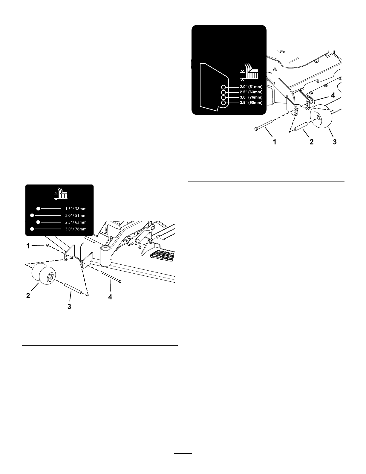
Einstellender
Antiskalpierrollen
InstallierenSiedieRollenfürdiemaximale
SchwebehöhedesMähwerksumeinLochtiefer.Die
RollensollteneinenAbstandvon6mmzumBoden
einhalten.StellenSiedieRollennichtsoein,dass
siedasMähwerkstützen.
1.StellenSiedieMaschineaufeineebeneFläche.
2.KuppelnSiedenZapfwellenantriebsschalter
aus,stellendieFahrantriebshebelindie
ARRETIERTENEUTRAL-Stellungundaktivierendie
Feststellbremse.
3.StellenSievordemVerlassender
BedienungspositiondenMotorab,ziehenSie
denSchlüsselabundwartenSie,bisalle
beweglichenT eilezumStillstandgekommen
sind.
4.StellenSiedieAntiskalpierrollen,wieinBild26
undBild27abgebildet.
Bild27
1.Schraube
2.Buchse4.Bundmutter
5.ZiehenSiedieBundmutteraufeinDrehmoment
von41bis47Nman.
g227783
3.Antiskalpierrolle
Bild26
1.Bundmutter3.Buchse
2.Antiskalpierrolle
g227785
4.Schraube
30
 Loading...