

Page 1
1/8 SCALE
REPLICA RADIAL
ENGINE
ASSEMBLY AND FINISHING
INSTRUCTIONS
The Top Flite Replica Radial Engine (hereafter
referred to as Radial ) is patterned after the Pratt &
Whitney radial engines that powered numerous
aircraft from the Golden Age of aviation. Modeled
to fit the Top Flite P-47D Thunderbolt, this 1/8th
scale Radial will fit any cowls with a frontal opening
of 5-1/2" to 6-1/4". Not only does the Radial
enhance scale appearance, but it also serves as
an air-flow baffle for more efficient engine cooling.
Top Flite Product Support:
3002 N Apollo Drive Suite 1
Champaign, IL 61822
Telephone: (217) 398-8970
Fax: (217) 398-7721
E-mail: airsupport@top-fl ite.com
WARNING
Do not attempt to start your engine unless the
radial has been modified to permit cooling airflow
to the engine! See text for more information.
© Copyright 2008 RADIALP08 v1.1
TOOLS AND SUPPLIES NEEDED (Not Included)
Hobby Knife with # 11 Blade (HCAR0100)
Hand Drill or Dremel
1/16" and 1/8" Drill Bits
6-Minute Epoxy (Great Planes
CA+ (Great Planes
1/8" x 8" x 8" Lite-ply
Round File or 1/2" Drum Sander
Small Paint Brushes
Paint (see painting instructions)
Scroll or Coping Saw
Rubber Cement or Spray Adhesive
100 & 240-Grit Sandpaper
®
Moto-Tool
®
Pro™, GPMR6014)
®
®
Pro™, GPMR6042)
ASSEMBLY
The following procedure covers the assembly and
modifications required for a flying model. Static display
models require no modification.
❑ 1.
Measure the inside diameter of your cowl about
1-1/2" from the frontal opening and match this size to the
concentric circles on the Baffle Template. The correct size
for the Top Flite P-47 is the innermost solid line on
the template.
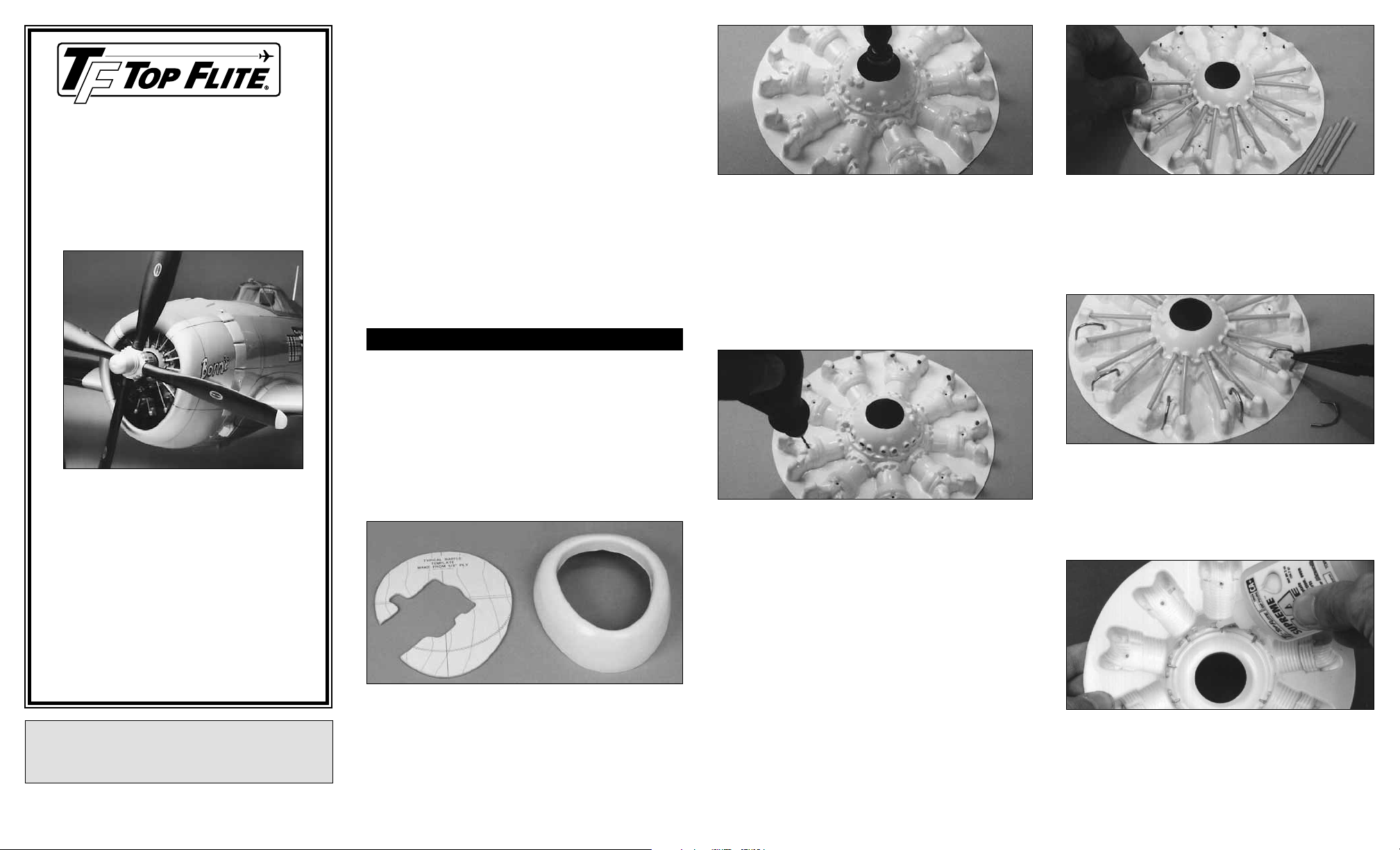
❑ 2. Trace or photocopy the Baffle Template, then glue
the copy to a sheet of 1/8" lite-ply (not included). Cut
around the circumference and the engine opening with a
scroll or coping saw.
❑ 3.
Trim the Radial to fit the lite-ply Baffle with a hobby
knife or scissors.
❑ 4. Cut away the prop shaft opening from the center of
the Radial. Smooth the edges with a round file or
drum sander.
❑ 5. Tape the Radial to the baffle, then test fit the
assembly inside the cowl. If necessary, sand the baffle
and Radial for a better fit.
❑ 6. Flight Modification — Trim away one of the
cylinders but leave excess backing material in place. This
material will be trimmed off during final fitting of
the engine.
❑ 7. Drill a 1/8" hole through each of the indented marks
around the perimeter of the crankcase and also through
the bottom of each rocker arm cover. Drill a 1/16" hole
through the dimple near the top of each cylinder.
❑ 8. Use 240-grit sandpaper to lightly sand the full length
of the 5 plastic tubes for better glue and paint adhesion.
Cut 18 pieces 2" long to use for the pushrod tubes.
❑ 9. Sand the 16" wire, then cut 9 pieces 1-1/2" long to
use for the ignition leads. Make a 90 degree bend 3/8"
from one end.
Note: As you will probably be removing at least one
cylinder when you use the Radial as an air baffle, you
need not install pushrod tubes and an ignition lead in
one cylinder. Complete all 9 cylinders if you will only be
using the Radial for static display.
Painting Hint: Some modelers find that it’s easier to
paint this type of structure before final assembly. If this is
your preference, skip down to the section on Painting.
Then return to step 10 when you are ready to proceed.
❑ 10. Insert the pushrod tubes into the rocker arm
covers and the crankcase as shown in the photo. They
should protrude inside the Radial about 3/32" at each
end of each piece. Don't worry about gluing them yet.
❑ 11. Insert the ignition leads into the cylinders.
NOTE: Bend the wires over the top of each cylinder so
that they touch the backing. They will be installed in the
baffle later.
❑ 12. Turn the Radial over and apply a drop of CA to
both ends of all push rod tubes and ignition leads.
❑ 13. Glue the Radial to the ply baffle with 6-minute
epoxy. Be sure to align the “removed cylinder” with the
opening in the baffle. Hint: Roughen the back surface of
the Radial with 100-grit sandpaper for a better bond.
Page 2
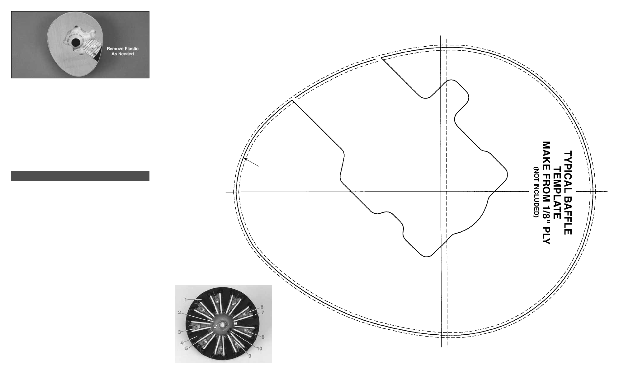
❑ 14. Tape the Radial assembly inside the cowl. Make
final adjustments to the fit between the cutouts and the
engine. By working from the inside it’s possible to remove
material from the Radial without affecting the pushrod
tubes and ignition leads. Pay special attention to provide
unrestricted throttle and needle valve movement.
❑ 15. When satisfied with the fit, smooth all rough
edges with fine sandpaper. Then paint the Radial (if not
already done).
Qty. Description Part No.
PARTS LIST
1 ABS Plastic Radial RADIAL08
5 8" Plastic Push Rod Tubes PLTB025
1 16" Wire for Ignition Leads WIRES58
1 Instruction Sheet RADIALP08
Baffle Template
The cutout in this baffle is sized to fit
a typical .60-size 2-stroke engine.
PAINTING SUGGESTIONS
We painted our prototype Radial with Testors Model
Enamel paint, then sprayed two light top-coats of satin
finish epoxy over the finished job. This finish withstands
fuel and normal wear and tear quite well.
If you are building a scale replica of a particular aircraft,
paint the Radial in similar colors to the full scale version.
The colors we chose represent typical P&W colors with
chrome plated pushrod tubes.
PAINTING SEQUENCE AND COLORS USED
Top Flite LustreKote
1. Entire Exterior – Gray Primer
Testors Model Master Enamel (Brushed on)
2. Crankcase – Gunship Gray
3. Cylinders – Euro Gray
4. Background – Light Gray or Flat Black
5. Pushrod Tubes – Silver
6. Ignition Leads – Red
7. Rocker Arm Covers – Black
8. “Spark Plug” Connectors – Gold or Copper
9. Cylinder Fins and Weathering – Silver & Black
Random Fine Lines On The Fins
10. Engine I.D. Plate – Black with Silver details
™
(Aerosol)
Use solid line for
Top Flite P-47D cowl.
11. Epoxy Satin Finish Clear Coat (Test clear coat to
make sure it is compatible with the Testors Enamel.)
 Loading...