

Page 1
]
WARBIRD DROP TANK
INSTRUCTIONS
Thank you for purchasing the Top Flite 108 Gallon Drop Tank
kit. This tank will add a great deal of realism and presence to
many 1/8th scale warbirds. The tank is lightweight and easy to
assemble and finish. It is easy to make droppable on a warbird
under construction. If you are going to add it to a model that is
already built, it would be easier to make it removable manually,
without servo control.
TANK ASSEMBLY
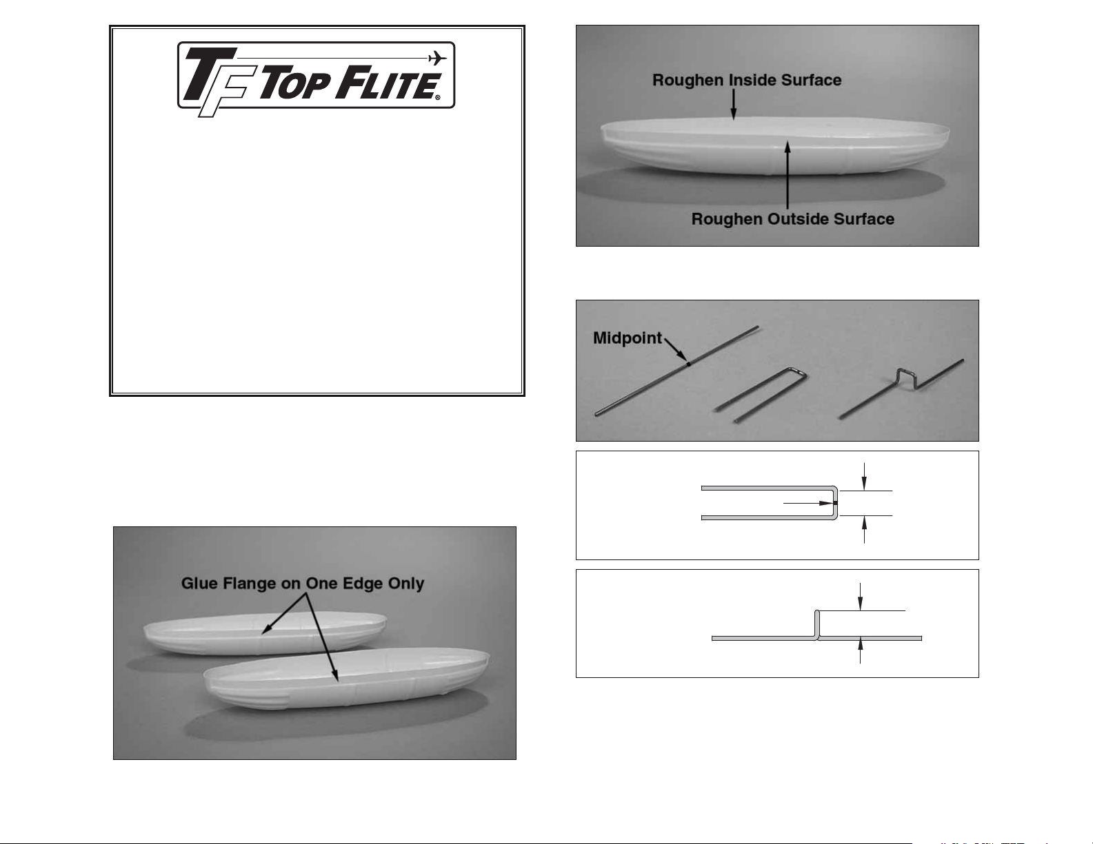
3. Use 220 or 150-grit sandpaper to roughen the edges of the
❑
flanges where the two halves will be glued together.
1. Lightly sand the outside of the drop tank halves with 400-grit
❑
sandpaper. This will help the primer and paint adhere to the surface.
2. Trim off the excess plastic to the cut lines on the inside of the
❑
tank with scissors or a hobby knife. Use 220-grit sandpaper to even
up the edges of the glue flange.
Sketch #1
MIDPOINT
Sketch #2
4. The supplied 0.046" dia x 3" steel wire needs to be bent by
❑
following these steps.
A. Mark the midpoint on the wire.
❑
B. Using Sketch #1 as a template, bend the wire to create a “U”
❑
shape as shown in the above image. The center section is 1/4" wide.
C. Using Sketch #2 as a template, bend the legs in opposite
❑
directions as shown in the above image. The center section has a
height of 1/4".
1/4" [6.35mm
1/4" [6.35mm]
Page 2
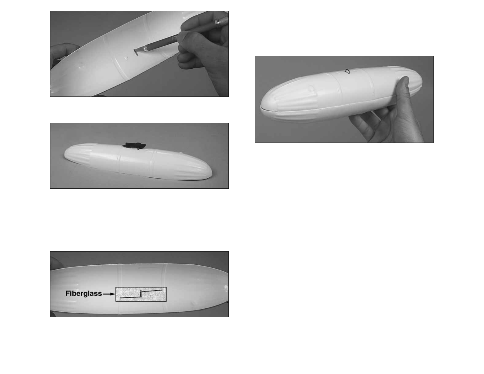
5. Cut out the slot in the top half of the tank to allow the Release
❑
Loop to exit through the top of the tank from the inside.
10. You may wish to add about 1/4 oz of nose weight (not included)
❑
to the inside nose of the tank. This will make the tank more neutrally
balanced when it falls. If you choose to add nose weight, roughen the
inside surface thoroughly and use epoxy to glue the weight securely
in place. A couple of old washers work well for this.
11. Tape the two halves of the tank together in several places with
❑
masking tape. Glue the two halves together by wicking thin CA into the
seam. Do not use accelerator as it will weaken the plastic.
12. Prime and paint the tank as desired.
❑
6. Use 150-grit sandpaper to thoroughly roughen the inside of the
❑
tank where the release hook is secured. With the Release Loop
inserted through the top half of the tank, test fit the Release Loop to
the Release Mechanism to make sure there is no interference.
7. Roughen the portion of the Release Loop that will be glued to the
❑
tank with 150-grit sandpaper.
8. Glue the Release Loop to the inside of the top half of the tank
❑
with 30-minute epoxy and the supplied 1" x 3" fiberglass tape. Allow
the epoxy to cure.
9. Check the fit of the top and bottom halves of the tank carefully.
❑
Sand away any obstructions so you have a good fit.
TYPICAL INSTALLATION OF THE
RELEASE MECHANISM
Note: These are the latest instructions for the installation of this
drop tank. Please disregard any earlier instructions from any of
our plans or manuals.
Note: These are generic instructions explaining how to install the
Release Mechanism on a Warbird’s wing. Depending on the airplane or location on the airplane that you are installing your
release mechanism on, the procedure may vary slightly.
1. Reinforce the area that you are going to install the Release
❑
Mechanism on with hardwood blocks, or stringers. You can also use
fiberglass if you wish.
2. Position the Release Mechanism in the location where you
❑
want to install it. Route a thin flexible cable (Sullivan #507) from the
release servo to the release tab. Tin the cable with silver solder at
the release tab end and put a Z-bend in it. If you wish, you could also
use a string tied to the release tab and to the servo arm.
Page 3

PARTS LIST
#4 x 5/8"
Screws
Release
Tab
3. Drill two 1/16" holes for the Release Mechanism's mounting
❑
#2 x 3/8"
Screws
Release
Mechanism
screws. Using the sketch above as a sample, drill four holes for the
drop tank positioning screws. The location of these screws will vary
from airplane to airplane. Use thin CA to harden all the holes. Install
the mechanism with two #2 x 3/8" screws included. Install the four
#4 x 5/8" sheet metal screws included at the outer holes. These
screws will be used to position the tank in the correct attitude.
Part # Qty. Description
FORQ2219 .................. 1 .................................. Release Mechanism
P4076DT01 ................. 1 ...............................................Tank Bottom
P4076DT01 ................. 1 .....................................................Tank Top
SCRW024 .................... 2 ................... #2 x 3/8" Sheet Metal Screws
SCRW010 .................... 4 ................... #4 x 5/8" Sheet Metal Screws
GLTP018...................... 1 ..............................1" x 3" Fiberglass Tape
WIRES114 ................... 1 .............................. 0.046" x 3" Music Wire
If you need to order replacement parts, send a check or money order
for the total amount (IL residents add 8.75% tax) plus $9.99 shipping. Add $9.99 for C.O.D. orders to:
Top Flite Models
3002 N Apollo Drive, Suite 1
Champaign, IL 61822
Ph: (217) 398-8970, Fax: (217) 398-7721
E-mail: productsupport@top-fl ite.com
4. Install the tank on the Release Mechanism and tighten or
❑
loosen the #4 x 5/8" screws until you get the desired tank position.
Ideally, the tank should have a slightly negative attitude so that it falls
away from the airplane as soon as it is released. Wick thin CA on the
screws to keep them from moving.
You can add even more realism to your warbird by installing an
authentic multiple blade static propeller, a replica radial engine, a
pilot and a cockpit kit to your airplane. These are available for most
of our Top Flite airplanes. Visit Top Flite’s web site at www.top-flite.
com for more information.
Printed in USA © 2010 Hobbico®, Inc. V1.1 DT18P01
 Loading...