

Page 1
WARRANTY:Top Flite Models guarantees this kit
to be free from defects in both material and
workmanship at the date of purchase. This
warranty does not cover any component parts
damaged by use or modification. In no case shall
Top Flite’s liability exceed the original cost of the
purchased kit. Further, Top Flite reser ves the right
to change or modify this warranty without notice.In
that Top Flite has no control ov er the final assemb ly
or material used for final assembly, no liability shall
be assumed nor accepted for any damage
resulting from the use by the user of the final user-
assembled product. By the act of using the user-
assembled product, the user accepts all resulting
liability.If the buyer is not prepared to accept the
liability associated with the use of this product,
the buyer is advised to return this kit
immediately in new and unused condition to
the place of purchase. To make a warranty claim
send the defective part or item to Hobby Services
at the address below.
Hobby Services
3002 N. Apollo Dr. Suite 1
Champaign IL 61822
USA
Include a letter stating your name, return shipping
address, as much contact information as possible
(daytime telephone number, fax number, e-mail
address), a detailed description of the problem and
a photocopy of the purchase receipt. Upon receipt
of the package the problem will be evaluated as
quickly as possible.
Top Flite Models • Champaign, Illinois • Telephone (217) 398-8970 ext. 5 • Fax (217) 398-7721 • productsupport@top-flite.com
READ THROUGH THIS INSTRUCTION BOOK FIRST. IT CONTAINS IMPORTANT INSTRUCTIONS AND WARNINGS CONCERNING THE ASSEMBLY AND USE OF THIS MODEL.
ARO6PO4 V1.0
Entire Contents © Copyright 2004
Wingspan: 81 in [2060mm]
Wing Area: 1089 sq in [70.2 dm
2
]
Weight: 12–14 lb [5440–6350 g]
Wing Loading: 25–30 oz/sq ft [76–92 g/dm
2
]
Fuselage Length: 61.5 in [1560mm]
Radio: 6-channel, 1 high-torque servo, 5-7
standard servos, 1 micro servo (optional)
Engine: .61–.91 cu in [10.0–15.0cc] two-stroke,
.91 cu in [15.0cc] four-stroke
Top Flite Gold Edition Piper Arrow II Assembly Instructions
™
USA
MADE IN
Page 2

TABLE OF CONTENTS
INTRODUCTION....................................................2
SAFETY PRECAUTIONS......................................3
DECISIONS YOU MUST MAKE ............................4
Radio Equipment................................................4
Engine Recommendations.................................4
Landing Gear Options ........................................4
Cockpit & Pilots ..................................................5
Trim Scheme/Finishing Supplies........................5
ADDITIONAL ITEMS REQUIRED .........................5
Hardware and Accessories................................5
Adhesives and Building Supplies.......................5
Optional Supplies and Tools...............................6
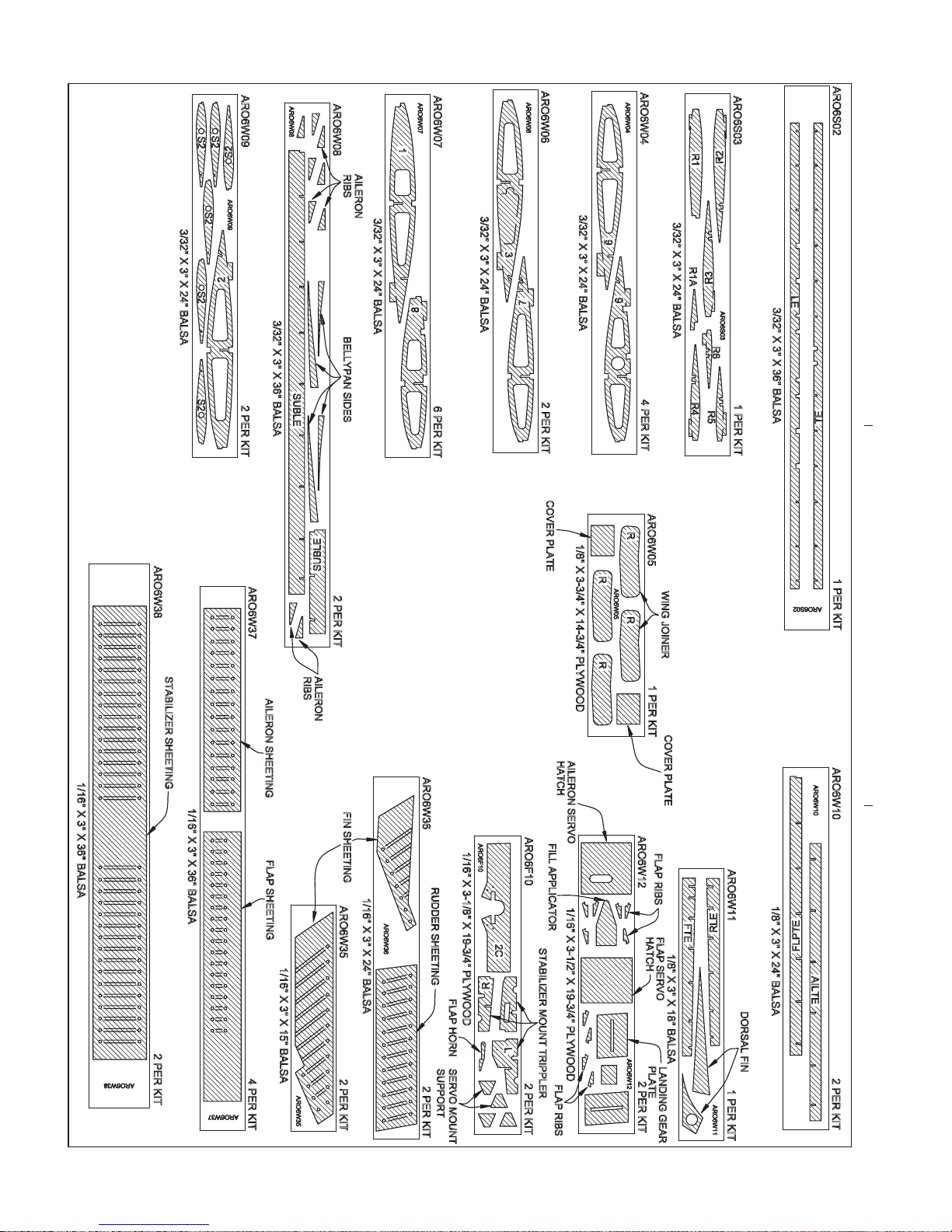
IMPORTANT BUILDING NOTES ..........................6
COMMON ABBREVIATIONS................................7
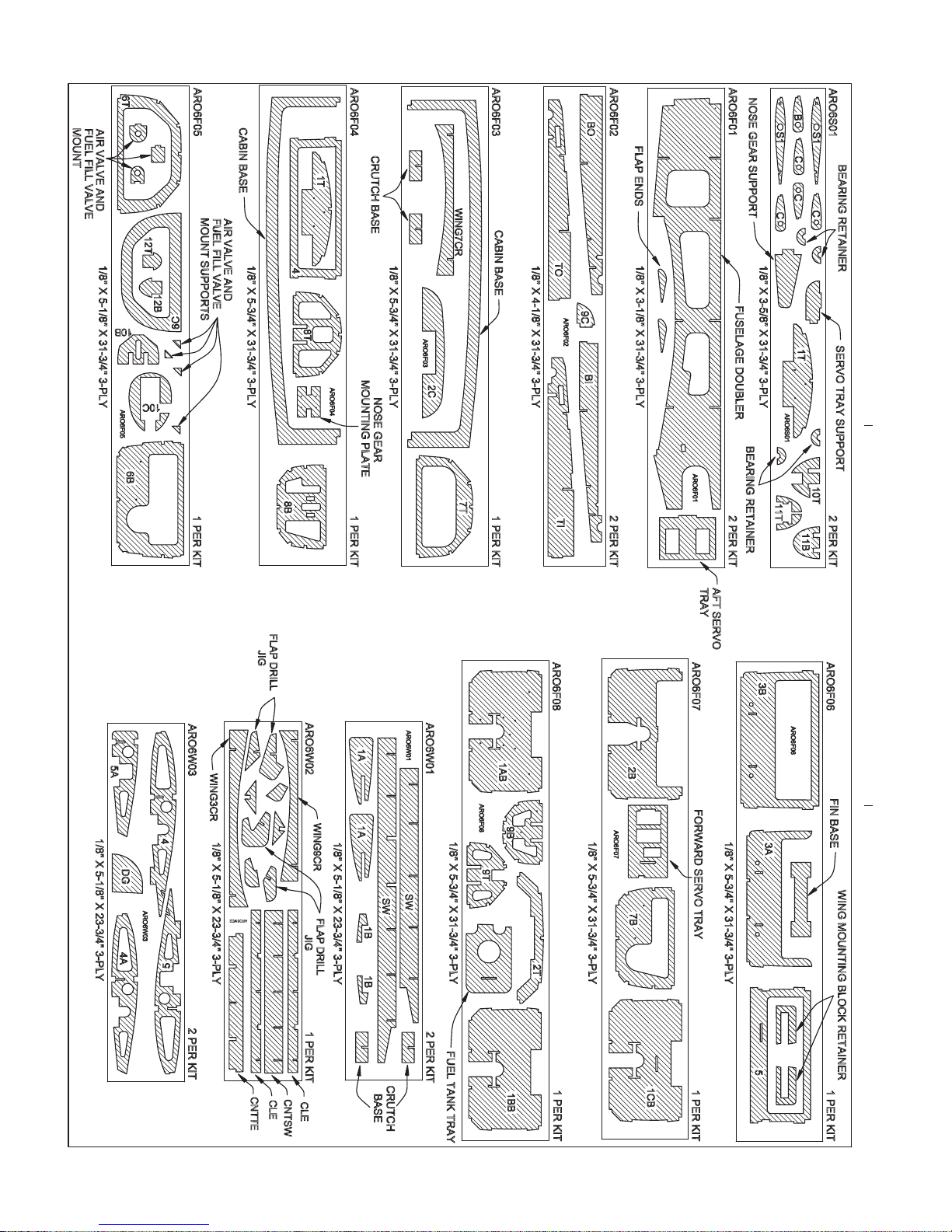
DIE-CUT PATTERNS ........................................8&9
PREP ARE T O BUILD...........................................10
Build the Tail Surfaces ......................................10
Build the Vertical Stabilizer (Fin)......................10
Finish the Fin & Rudder...................................13
Build the Horizontal Stabilizer (Stab)...............14
BUILD THE WING................................................18
Make the Wing Skins.......................................18
Build the Center Panel.....................................18
Build the Outer Panels.....................................21
Fit the Fixed Landing Gear..............................23
Fit the Retractable Landing Gear.....................23
Finish Fitting the Landing Gear........................24
Sheet the Bottom of the Wing..........................25
Mount the Hatches and Landing Gear.............26
Build the Ailerons.............................................28
Build the Flaps.................................................29
Hinge the Flaps ................................................31
Mount the Flap and Aileron Servos .................32
Join the Wing...................................................33
BUILD THE FUSELAGE......................................34
Frame the Bottom of the Fuselage..................34
Sheet the Bottom of the Fuselage...................37
Mount the Fixed Nose Gear.............................39
Fit the Retractable Nose Gear.........................39
Mount the Engine .............................................40
Connect the Nose Steering and Throttle .........40
Cover the Horizontal Stabilizer.........................41
Mount the Horizontal Stabilizer........................43
Mount the Vertical Stabilizer (Fin)....................45
Sheet the Aft End of the Fuselage...................47
Build the Dorsal Fin..........................................48
Finish the Top of the Fuselage.........................48
Mount the Cabin Top ........................................49
Fit the Tail Cone...............................................51
FINAL CONSTRUCTION.....................................53
Mount the Cowl................................................53
Mount the Wing ................................................56
Build the Belly Pan...........................................57
FINISH THE MODEL ...........................................58
Covering...........................................................58
Painting............................................................61
Final Assembly and Systems Hookup.............62
Mount the Pilots...............................................66
Glue on the External Stringers ............................67
Apply the Decals..................................................67
Add Panel Lines ...................................................67
GET THE MODEL READY TO FLY .....................67
Center the Controls & Check the Directions ....67
Set the Control Throws....................................68
Balance the Model (C.G.) ................................69
Balance the Model Laterally.............................69
PREFLIGHT.........................................................69
Identify Your Model...........................................69
Charge the Batteries........................................69
Balance Propellers...........................................70
Ground Check..................................................70
Range Check ...................................................70
ENGINE SAFETY PRECAUTIONS .....................70
AMA SAFETY CODE..........................................71
IMAA SAFETY CODE.........................................71
CHECK LIST........................................................72
FLYING ................................................................72
Takeoff..............................................................73
Flight ................................................................73
Landing ............................................................73
Fuselage/Wing Plan.........................center section
INTRODUCTION
Congratulations and thank you for purchasing the Top
Flite
®
Gold Edition
Piper Arrow II. One of the unique
features of this Top Flite
Gold
kit is the scale
corrugations on the vertical and horizontal stab and on
all of the control surfaces. The corrugations are
optional, but add much to the scale effect of this model.
While this kit can be assembled by intermediate
builders, note that the corrugations take additional time,
skill and patience.Read through the manual to see ho w
the corrugations are made and how they are covered
before making a decision. Should you decide not to
build your Arrow with corrugated control surfaces
simply replace the die-cut, corrugated skins with
regular sheeting (not included).
Another option is to build the plane with fixed or
retractable landing gear. This kit was designed to fit
Robart retracts, so should you decide to install another
brand any modifications required would be up to you.
Flaps are another option. The manual is primarily
“geared” toward building the Arrow with flaps, but
instructions are also provided for building the model
without flaps.
Lastly, the cabin top is vacuum-formed from a clear,
PETG plastic sheet.The window outlines are molded
in.Finishing the cabin top requires masking, sanding
and painting around the windows. Since the cabin
top is molded from PETG, it may be painted with Top
Flite LustreKote
®
.
The level of scale detail you wish to achieve is up to
you. Simply by following the instructions you’ll end up
with a model that very much represents a Piper Arrow
II. But you could also “go all-out” by adding even more
scale details to make a model that would be a
contender in any level of scale competition.
For the latest technical updates or manual corrections
to the Piper Arrow visit the Top Flite web site at
www
.top-flite.com. Open the “Airplanes” link, then
select the Piper Arrow. If there is new technical
information or changes to this model a “tech notice”bo x
will appear in the upper left corner of the page.
- 2 -
Page 3
AMA
We urge you to join the AMA (Academy of Model
Aeronautics) and a local R/C club. The AMA is the
governing body of model aviation and membership
is required to fly at AMA clubs. Though joining the
AMA provides many benefits, one of the primary
reasons to join is liability protection. Coverage is not
limited to flying at contests or on the club field. It
even applies to flying at public demonstrations and
air shows. Failure to comply with the Safety Code
(excerpts printed in the back of the manual) may
endanger insurance coverage. Additionally, training
programs and instructors are available at AMA club
sites to help you get started the right way.There are
over 2,500 AMA chartered clubs across the country.
Contact the AMA at the address or toll-free phone
number below:
Academy of Model Aeronautics
5151 East Memorial Drive
Muncie, IN 47302-9252
Tele. (800) 435-9262
Fax (765) 741-0057
Or via the Internet at: http://www.modelaircraft.org
IMPORTANT!!!
Two of the most important things you can do to
preserve the radio controlled aircraft hobby are to
avoid flying near full-scale aircraft and avoid flying
near or over groups of people.
IMAA
The Top Flite Piper Arrow II is an excellent scale
model and is eligible to fly in IMAA ev ents .The IMAA
(International Miniature Aircraft Association) is an
organization that promotes non-competitive flying of
giant-scale models. If you plan to attend an IMAA
event, obtain a copy of the IMAA Safety Code by
contacting the IMAA at the address or telephone
number below, or by logging on to their web site at:
www.fly-imaa.org/imaa/sanction.html
IMAA
205 S. Hilldale Road
Salina, KS 67401
(913) 823-5569
Scale Competition
The outline of this Top Flite Gold Edition Piper Arrow
II was derived from three-view drawings and photos.
The scale is 1:4.6 which was calculated from
averaging the scale wingspan and the scale length.
Though the Top FlitePiper Arrow II may not hav e the
same level of detail as an “all-out” scratch-built
competition model, it is still a relatively detailed scale
model and is therefore ideal for competing in R/C
Sport Scale (Sportsman and Expert), R/C
Fun Scale
(Division 1 or Division 2), or even the Team Scale
classes in AMA competition (we receive many
favorable reports of Top Flite models in scale
competition!).In Fun Scale, to receive the five points
for scale documentation, the only proof required that
a full size aircraft of this type did exist in your
paint/markings scheme is a single sheet such as a
kit box cover from a plastic model, a photo, or a
profile painting, etc. If the photo is in black and white
other written documentation of color must be
provided. Contact the AMA for a rule book with full
details. Note: The propeller on the model on the kit
box cover is oversize for the engine, but provides a
scale appearance. It is a Master Airscrew 13 x 8
three-blade (MASQ1938). The model could actually
be flown with a three-blade prop, but it must be the
correct size to match your engine.
If you would like photos of the full-size Piper Arrow
for scale documentation, or if you would like to study
the photos to add more scale details, photo packs
are available from:
Bob’s Aircraft Documentation
3114 Y uk on Ave
Costa Mesa, CA 92626
Telephone: (714) 979-8058
Fax:(714) 979-7279
e-mail: www.bobsairdoc.com
1. Your Piper Arrow should not be considered a toy,
but rather a sophisticated, working model that
functions very much like a full-size airplane.
Because of its performance capabilities, the Piper
Arrow, if not assembled and operated correctly,
could possibly cause injury to yourself or spectators
and damage to property.
2. You must assemble the model according to the
instructions. Do not alter or modify the model, as
doing so may result in an unsafe or unflyable model.
In a few cases the instructions may differ slightly
from the photos. In those instances the written
instructions should be considered as correct.
3. You must tak e time to build straight,trueand strong.
4. You must use an R/C radio system that is in first-
class condition, and a correctly sized engine and
components (fuel tank, wheels, etc.) throughout the
building process.
5. You must correctly install all R/C and other
components so that the model operates correctly on
the ground and in the air.
6. You must check the operation of the model before
every flight to insure that all equipment is operating and
that the model has remained structurally sound. Be
sure to check clevises or other connectors often and
replace them if they show any signs of wear or fatigue.
7. If you are not an experienced pilot or have not
flown this type of model before, we recommend that
you get the assistance of an experienced pilot in
your R/C club for your first flights. If you’re not a
member of a club, your local hobby shop has
PRO TECT YOUR MODEL,
YOURSELF & OTHERS
FOLLO W THESE IMPORTANT
SAFETY PRECAUTIONS
- 3 -
Page 4

- 4 -
information about clubs in your area whose
membership includes experienced pilots.
8. While this kit has been flight tested to exceed
normal use, if the plane will be used for extremely
high stress flying, such as racing, or if an engine
larger than one in the recommended range is used,
the modeler is responsible for taking steps to
reinforce the high stress points and/or substituting
hardware more suitable for the increased stress.
Remember: Take your time and follow the
instructions to end up with a well-built model
that is straight and true.
Before starting to build, compare the parts in this kit
with the Parts List and die drawings and note any
missing parts. Also inspect all parts to make sure
they are of acceptable quality. If any parts are
missing, broken or defective, or if you have any
questions about building or flying this airplane,
please contact Top Flite at the address or telephone
number below. If requesting replacement parts,
please provide the full kit name (Top Flite Gold
Edition Piper Arrow) and the part numbers as listed
in the Parts List.
Top Flite Product Support
3002 N Apollo Drive Suite 1
Champaign, IL 61822
Telephone: (217) 398-8970
Fax:(217) 398-7721
E-mail: productsupport@top-flite.com.
DECISIONS YOU MUST MAKE
This is a partial list of items required to finish the
Piper Arrow that may require planning or decision
making before starting to build. Order numbers are
provided in parentheses.
RADIO EQUIPMENT
Even though the Piper Arrow is giant-scale, it’s
basically a “.60-size” model. Therefore, the Arrow
doesn’t require any specialized, heavy-duty radio
gear.It may be flown safely with standard ser vos on
all of the flying surfaces except for the full-flying
stabilizer. The stabilizer should be controlled by a
ball bearing servo with at least 50 oz.-in. of torque.
Servo extensions and Y-harnesses will also be
required. Following is a list of servos and other gear
used to build the Piper Arrow as shown in this
manual. If you set up your model differently, other
radio gear may be required. Note: All of the part
numbers provided for R/C gear are for Futaba.
®
❏ (1) Stabilizer servo with at least 50 oz.-in. of
torque (Futaba S9001 or similar—FUTM0075)
❏ (5) Standard servos (1-nose wheel steering,
1-throttle, 2-ailerons, 1-rudder)
❏ (2) Hobbico 24"[610mm] servo extensions (for
ailerons—HCAM2721)
❏ (3) Hobbico 12"[305mm] servo extensions (for
stabilizer and rudder servos and coming from
receiver to hook up ailerons —HCAM2711)
❏ (1) Futaba dual extension cord (for ailerons—
FUTM4130)
A Great Planes Switch & Charge Jack Mounting Set
was also used (GPMM1000)
The following items will also be required if
building optional flaps:
❏ (2) Standard servos
❏ (1) Hobbico Y-harness (HCAM2751)
❏ (1) 12"[305mm] servo extension (from receiver
to flap Y-harness—HCAM2711)
If installing retractable landing gear this
additional radio equipment will also be required.
❏ (1) Micro servo
❏ (1) 6"[150mm] servo extension (HCAM2701)
A receiver battery pack with a minimum of 1,000mAh
is also required. (Futaba HR4RB, FUTM1380)
ENGINE RECOMMENDATIONS
The engine size recommendations for the Piper Arrow
are straightforward.See the recommendations on the
cover of this manual.Keep in mind that this is a scale
model of a four-seat, general aviation aircraft, not an
aerobatic air show plane. It is intended to fly “on the
wing” and will do so easily with a .61 two-stroke or a
.91 four-stroke.Do not overpower this aircraft. If using
an O.S.
®
Max SF or SX engine the Top Flite in-cowl
muffler may be used:
❏ TOPQ7920 Top Flite header for in-cowl muffler
(For O.S. Max engines)
❏ TOPQ7917 Top Flite In-cowl muffler
LANDING GEAR OPTIONS
The Piper Arrow requires two 3"[75mm] main wheels
and one 2-1/2"[64mm] nose wheel. If building the
Arrow with fixed landing gear, any brand of the
appropriate-size wheels is suitable. With retracts,
Robart wheels are recommended as they are narrow
and fit better into the wing. Note that a Robart 2-
1/4"[57mm] nose wheel is recommended as it will fit
on the nose strut better than a 2-1/2"[64mm] wheel
(the Robart 2-1/4"[57mm] wheel is actually closer to
2-3/8"[60mm], so it is only 1/8"[3mm] smaller than
recommended). Following are the part numbers for
the recommended wheels:
❏ Great Planes 3"[75mm] main wheels
(GPMQ4225)
❏ Great Planes 2-1/2"[64mm] nose wheel
(GPMQ4223)
-or-
❏ Robart 3"[75mm] main wheels (ROBQ1514)
❏ Robart 2-1/4"[57mm] nose wheel (ROBQ1511)
NOTE: We, as the kit manufacturer, provide you
with a top quality kit and great instructions, but
ultimately the quality and flyability of your finished
model depends on how you build it;therefore, we
cannot in any way guarantee the performance of
your completed model, and no representations
are expressed or implied as to the performance or
safety of your completed model.
Page 5

The following items were also used to assemble
the Piper Arrow with retractable landing gear:
❏ Robart #530ARW pneumatic retractable
landing gear kit for Piper Arrow (ROBQ1621)
❏ Robart #188VR variable rate air control kit
(ROBQ2302, includes air tank, variable rate
valve, lines, fittings)
❏ (1 pkg.) Robart #190 Air Line Quick
Disconnects (ROBQ2395)
❏ Robart hand pump with gauge (or suitable
replacement) (ROBQ2363)
❏ Micro servo and 6"[150mm] servo extension
(previously listed under “Radio Equipment”)
❏ (2 pkgs.) Great Planes 0-80 (1/16”) threaded
ball link ball (GPMQ3842)
❏ Optional: 3/4 oz. [20g] glass cloth to reinforce
wing sheeting inside wheel wells (HCAR5000)
COCKPIT AND PILOTS
A scale cockpit kit is also available for this model
(TOPQ8414). It includes the floor, sides and back,
instrument panel, dashboard and four seats. Even
though the cockpit kit can’t be seen in great detail
unless you are up close or have the cabin top
removed, it adds MUCH to the overall scale effect
and really “finishes” the model. Installation
instructions are also included with the cockpit kit.
Two Williams Brother’s #62600 Sportsman 3"[75mm]
(1/4-scale) pilots (WBRQ2626) were used. Since the
pilots are not full-body, a platform was made from
3/32"[2.4mm] hard balsa to support them. Acrylic
paint found at craft stores and hobb y shops was used
for painting the pilots.Acrylic paint is favored because
it is easy to use and washes with water.
TRIM SCHEME/FINISHING SUPPLIES
The trim scheme on the model on the kit box cover
was inspired by a full-size Piper Arrow. All of the
wood surfaces were covered with Top Flite
MonoKote
®
. The cabin top, cowl and tail cone were
painted with Top Flite LustreK ote
®
.Modelers who are
experienced in the application of iron-on coverings
will find this trim scheme of medium difficulty. If a
simpler or different trim scheme is desired this one
could be used as a reference, or just follow the trim
scheme of another full-size subject. Following are
the part numbers of the MonoKote, LustreKote and
covering tools used.
COVERING
❏ (2) 6’ [1.8m] rolls White MonoKote (TOPQ0204)
❏ (1) 6’ [1.8m] roll Metallic red MonoKote
(TOPQ0405)
❏ (1) 6’ [1.8m] roll Metallic gold MonoKote
(TOPQ0404)
PAINT
❏ (2) White primer LustreKote (TOPR7801)
❏ (1) Jet White LustreKote (TOPR7204)
❏ (1) Metallic red LustreKote (TOPR7405)
❏ (1) Crystal clear-gloss LustreKote (TOPR7200)
❏1 roll of 1/4"[6.4mm] Metallic gold striping tape was
also used on the cowl and tail cone (GPMQ1530)
COVERING T OOLS
❏ Top Flite MonoKote trim seal iron (TOPR2200)
❏ 21
st
Century sealing iron (COVR2700)
❏ 21
st
Century iron cover (COVR2702)
ADDITIONAL ITEMS REQUIRED
HARDWARE AND ACCESSORIES
In addition to the items listed in the “Decisions Y ou
Must Make” section, follo wing is the list of hardw are
and accessories required to finish the Piper Arrow.
Order numbers are provided in parentheses.
❏ Propeller and spare propellers suitable for
your engine
❏ 14 oz. [420cc] fuel tank (GPMQ4106)
❏ Fuel line (3’ [910mm], GPMQ4131)
❏ 2-1/2"[65mm] spinner (white-GPMQ4520, black-
GPMQ4521, red-GPMQ4522)
-or-
❏ Three-blade aluminum True Turn spinner
(TRUQ2514)
❏ Acrylic paint and paint brushes for painting pilot
(found at craft stores)
❏ Auto body filler (Bondo or similar)
❏ R/C foam padding (1/4"[6mm] HCAQ1000,
1/2"[13mm] HCAQ1050)
❏ Sullivan #521 Kevlar pull-pull control cable set
(for nose wheel steering, SULQ3121)
❏ If building flaps: (1 pkg. of 6) Robart Super
Hinge Points (ROBQ2509)
ADHESIVES AND BUILDING SUPPLIES
In addition to common modeling tools (screw drivers,
hobby knives, drill, etc.), this is the “shor t list” of the
most important items required to build the Piper
Arrow.
We recommend Great Planes Pro™ CA and
Epoxy glue.
❏ 2 oz. [60g] Thin Pro CA (GPMR6003)
❏ 2 oz. [60g] Medium Pro CA+ (GPMR6009)
❏ 1/2 oz. [15g] Thick Pro CA- (GPMR6013)
❏ Pro 30-minute epoxy (GPMR6047)
❏ Pro 6-minute epoxy (GPMR6045)
❏ Pro Aliphatic resin (2 oz. [60g], GPMR6160)
❏ NHP balsa filler (NHPR2211)
❏ Plan protector (GPMR6167) or wax paper
❏ Drill bits: 1/16"[1.6mm], 5/64"[2mm],
3/32"[2.4mm], 7/64"[2.8mm], 1/8"[3.2mm],
9/64"[3.6mm], 5/32"[4mm], 11/64"[4.4mm],
3/16"[4.8mm], 13/64"[5.2mm], 7/32"[5.6mm],
15/64 [6mm], 1/4"[6.4mm], 17/64"[6.7mm],
9/32"[7.1mm]
❏ 8-32 tap and drill set (GPMR8103)
❏ 1/4-20 tap and drill set (GPMR8105)
❏ Tap handle (GPMR8120)
❏ Small metal file
❏ Stick-on segmented lead weights (GPMQ4485)
❏ Silver solder w/flux (GPMR8070)
❏ #1 Hobby knife (HCAR0105)
❏ #11 blades (100-pack, HCAR0311)
- 5 -
Page 6
❏ Single-edge razor blades (100-pack, HCAR0312)
❏ Small T-pins (100, HCAR5100)
❏ Medium T-pins (100, HCAR5150)
❏ Large T-pins (100, HCAR5200)
❏ Sanding tools and sandpaper assortment (
see
Easy-Touch Bar Sander section)
❏ 16"x 48"[410 x 1220mm] Great Planes Pro
Building Board (GPMR6950)
❏ Curved-tip canopy scissors for trimming plastic
parts (HCAR0667)
OPTIONAL SUPPLIES AND TOOLS
Here is a list of optional tools mentioned in the
manual that will help you build the Piper Arrow.
❏ 2 oz. [57g] spray CA activator (GPMR6035)
❏ 4 oz. [113g] aerosol CA activator (GPMR634)
❏ CA applicator tips (HCAR3780)
❏ CA debonder (GPMR6039)
❏ 3M 75 repositionable spray adhesive
(MMMR1900)
❏ Kyosho
®
masking film (KYOR1040)
❏ Epoxy brushes (6, GPMR8060)
❏ Mixing sticks (50, GPMR8055)
❏ Mixing cups (GPMR8056)
❏ Builder’s Triangle Set (HCAR0480)
❏ Metal Template Set (30/60/90 and 45 degree
triangles, HCAR0500)
❏ 36"metal ruler (HCAR0475)
❏ Robart Super Stand II (ROBP1402)
❏ 24"x 36"[460 x 910mm] Builder’s Cutting Mat
(HCAR0456)
❏ 16"x 48"[410 x 1220mm] building board
(GPMR6950)
❏ Fuel filler valve for glow fuel (GPMQ4160)
❏Hobbico Duster
™
can of compressed air (HCAR5500)
❏ Masking tape (TOPR8018)
❏ Milled fiberglass (GPMR6165)
❏ Microballoons (TOPR1090)
❏ Threadlocker thread locking cement
(GPMR6060)
❏ Denatured alcohol (for epoxy clean up)
❏ K & S #801 Kevlar thread (for stab alignment)
❏ Panel Line Pen (TOPQ2510)
❏ Rotary tool such as Dremel
❏ Rotary tool reinforced cut-off wheel (GPMR8200)
❏ Servo horn drill (HCAR0698)
❏ Hobby Heat
™
Micro Torch II (HCAR0755)
❏ Dead Center
™
Engine Mount Hole Locator
(GPMR8130)
❏ AccuThrow
™
Deflection Gauge (GPMR2405)
❏ Precision Hinge Marking Tool (GPMR4005)
❏Slot Machine
™
hinge slotting tool (110V, GPMR4010)
❏ CG Machine™ (GPMR2400)
❏ Laser incidence meter (GPMR4020)
❏ Precision Magnetic Prop Balancer
™
(TOPQ5700)
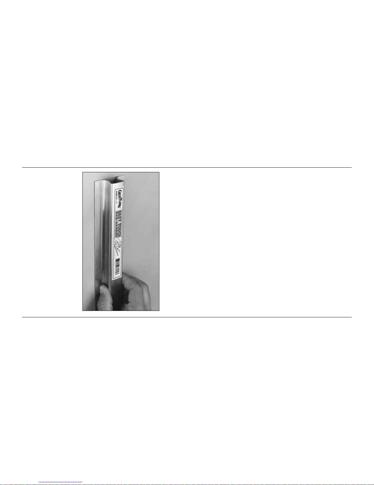
EASY-TOUCH
™
BAR SANDER
A flat, durable, easy-to-handle sanding tool is a
necessity for building a well-finished model. Great
Planes makes a complete range of Easy-Touch Bar
Sanders and replaceable Easy-Touch Adhesive-
backed Sandpaper.While building the Piper Arrow,
two 5-1/2"[140mm] Bar Sanders and two
11"[280mm] Bar Sanders equipped with 80-grit and
150-grit Adhesive-backed Sandpaper were used.
Here’s the complete list of Easy-Touch Bar Sanders
and Adhesive Backed Sandpaper:
5-1/2"[140mm] Bar Sander (GPMR6169)
11"[280mm] Bar Sander (GPMR6170)
22"[560mm] Bar Sander (GPMR6172)
33"[840mm] Bar Sander (GPMR6174)
44"[1120mm] Bar Sander (GPMR6176)
11"[280mm] Contour Multi-Sander (GPMR6190)
12’ [3.66m] roll of Adhesive-backed 80-grit
sandpaper (GPMR6180)
150-grit (GPMR6183)
180-grit (GPMR6184)
220-grit (GPMR6185)
Assortment pack of 5-1/2"[140mm] strips
(GPMR6189)
We also use Top Flite 320-grit (T OPR8030, 4 sheets)
and 400-grit (TOPR8032, 4 sheets) wet-or-dry
sandpaper for finish sanding.
IMPORTANT BUILDING NOTES
·
Whenever just
epoxy
is specified you may use
either
30-minute (or 45-minute) epoxy
or
6-minute epoxy.
When 30-minute epoxy is specified it is highly
recommended that you use only 30-minute (or 45-
minute) epoxy, because you will need the working
time and/or the additional strength.
·
Photos and sketches are placed before the step
they refer to. Frequently you can study photos in
following steps to get another view of the same parts.
·
Not all die-cut parts have a name, or their complete
name stamped on them, so refer to the die drawings
on pages 8 & 9 for identification. When it’s time to
remove the parts from their die sheets, if they are
difficult to remove, do not f orce them out.Instead, use
a sharp #11 blade to carefully cut the part from the
sheet, then lightly sand the edges to remove any
slivers or irregularities. Save some of the larger
scraps of wood.
- 6 -
Page 7

TYPES OF WOOD
BALSA BASSWOOD PLYWOOD
COMMON ABBREVIATIONS
Fuse = Fuselage
Stab = Horizontal Stabilizer
Fin = Vertical Fin
LE = Leading Edge
TE = Trailing Edge
LG = Landing Gear
" = Inches
mm = millimeters
During construction there will be several
occasions where epoxy cleanup will be
necessary .Instead of wasting whole paper to wels ,
stack three or four paper towels on top of each
other and cut them into small squares. This will
conserve paper towels and the little squares are
easier to use. For epoxy clean up dampen the
squares with denatured alcohol.
Plastic bags filled with lead shot are
recommended for building weights. They assume
the shape of curved surfaces and apply uniform
pressure. Shot can be purchased at sporting
goods stores where hunting supplies are sold. #6
shot is recommended.One 25 lb.[11kg] bag costs
about twenty dollars.Small, sealable food storage
bags can be used to hold the shot.Tape the bags
shut for security. Each bag holds about two to
three pounds. Twelve to fifteen bags is adequate
for this project.
1/64" = .4mm
1/32" = .8mm
1/16" = 1.6mm
3/32" = 2.4mm
1/8" = 3.2mm
5/32" = 4mm
3/16" = 4.8mm
1/4" = 6.4mm
3/8" = 9.5mm
1/2" = 12.7mm
5/8" = 15.9mm
3/4" = 19mm
1" = 25.4mm
2" = 50.8mm
3" = 76.2mm
6" = 152.4mm
12" = 304.8mm
15" = 381mm
18" = 457.2mm
21" = 533.4mm
24" = 609.6mm
30" = 762mm
36" = 914.4mm
METRIC CONVERSION
1" = 25.4mm (conversion factor)
- 7 -
0 10 20 30 40 50 60 70 80 90 100 110 120 130 140 150 160
Metric Scale
0" 1" 2" 3" 4" 5" 6"
Inch Scale
Page 8
- 8 -
DIE-CUT DRAWINGS
Page 9
- 9 -
DIE-CUT DRAWINGS
Page 10
PREP ARE T O BUILD
1. If you’ve already purchased the retractable landing
gear, or as soon as you do, take the air lines out of the
package.Unravel the lines and hang them somewhere
in your shop.When it’s time to install the lines they’ll be
nice and straight and they’ll be easier to work with.
2. Remove all the parts from the box.Use a ballpoint
pen (not a felt-tip pen) to lightly write the name or
size on each piece so it can be identified later. Use
the
die-cut patterns
on pages 8 & 9 to identify and
mark the die-cut parts before removing them from
their die sheets. Many of the parts already have
numbers stamped on them, but in some cases the
numbers are located beside the part or only on the
die drawings in the manual. If a part is difficult to
remove from its die sheet, don’t force it out. Instead,
cut around the part with a hobby knife and a #11
blade.After removing the parts from their die sheets,
lightly sand the edges to remove slivers or die-
cutting irregularities. As you proceed, it’s not
necessary to save every scrap of wood, but some of
the larger pieces of wood should be saved.
3. Separate the parts into groups such as stab, fin,
wing, and fuse. Store smaller parts in zipper-top
food storage bags.
BUILD THE T AIL SURF ACES
BUILD THE VERTICAL STABILIZER (FIN)
❏ 1. Unroll the fuselage plan, then re-roll it inside out
so it will lay flat.Cut out the fin plan, then position it ov er
your flat building board and cover it with Great Planes
Plan Protector or wax paper so glue will not adhere.
Note: If you plan to build your Arrow with any kind of a
scale lighting system, now is the time to drill or cut any
holes in the ribs necessary to accommodate the wiring.
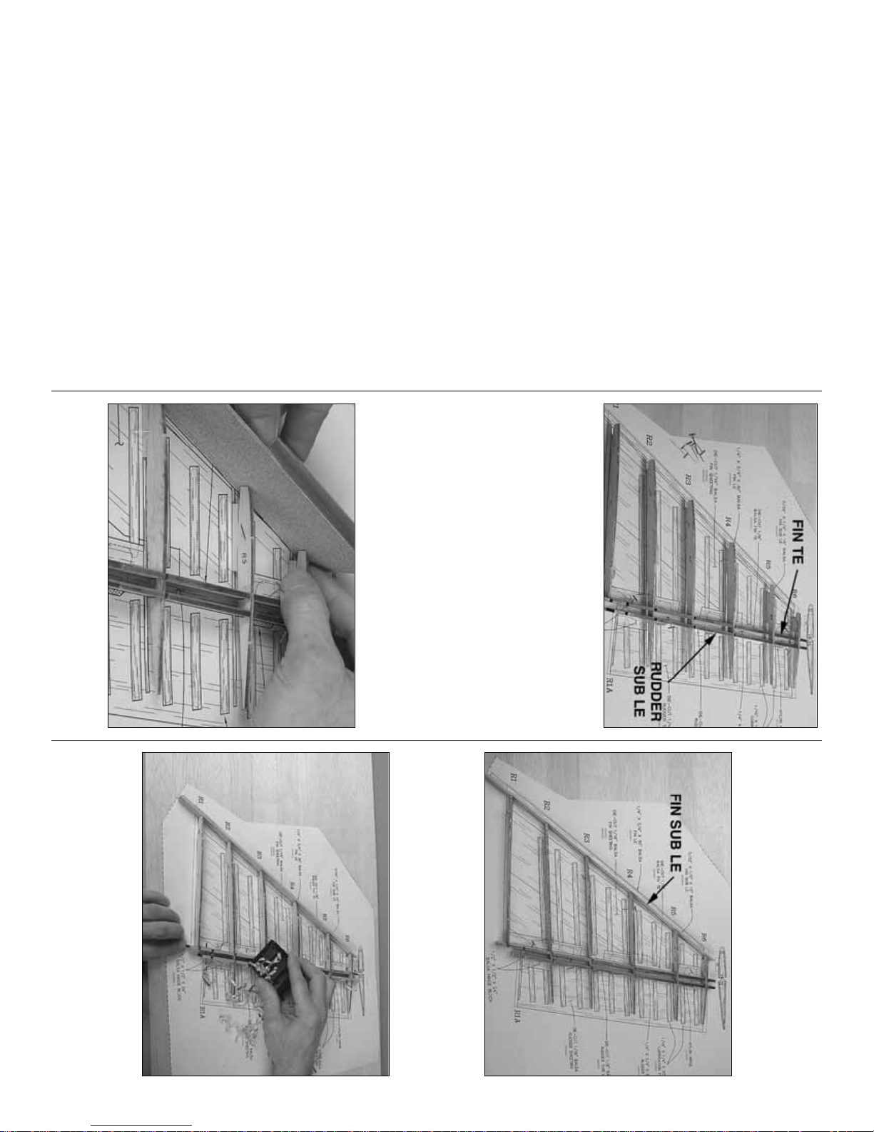
❏ 2. Fit the die-cut 3/32"[2.4mm] balsa fin ribs R1
through R6 into the notches of the die-cut 1/8"[3.2mm]
balsa fin trailing edge and the die-cut 1/8"[3.2mm]
balsa rudder sub leading edge. Note that all of the
notches are slightly oversize so the parts can fit at an
angle.Also note that a portion of the fin trailing edge and
rudder sub LE protrude below the assembly, but will be
trimmed off later.Make certain the parts are accurately
positioned over the plan and hold them to the building
board with T-pins.
❏ 3. Make sure all the jig tabs are fully contacting
the building board, then glue the assembly together.
❏ 4. Use a bar sander with 80-grit sandpaper to
sand a bevel on the leading edge of all the ribs. Do
one rib at a time starting with r ib R6 at the top. Hold
the rib with your fingers and draw the bar sander
down past, resting it against the other ribs to get the
correct angle.
❏ 5. Center the 3/32"x 1/2"x 15"[2.4 x 12.7 x
380mm] balsa fin sub leading edge vertically on the
front of the ribs, then glue it into position.
❏6. Use a razor plane and/or a bar sander to shape
the top (left side) of the sub leading edges and the
trailing edge so they are even with the ribs.
Note: Make sure none of the T-pins protrude above
any of the parts so they won’t catch.
- 10 -
Page 11
❏ 7. Glue the die-cut 3/32” [2.4mm] balsa rudder
rib R1A into position. If necessary, sand R1A to
blend with the rest of the structure.
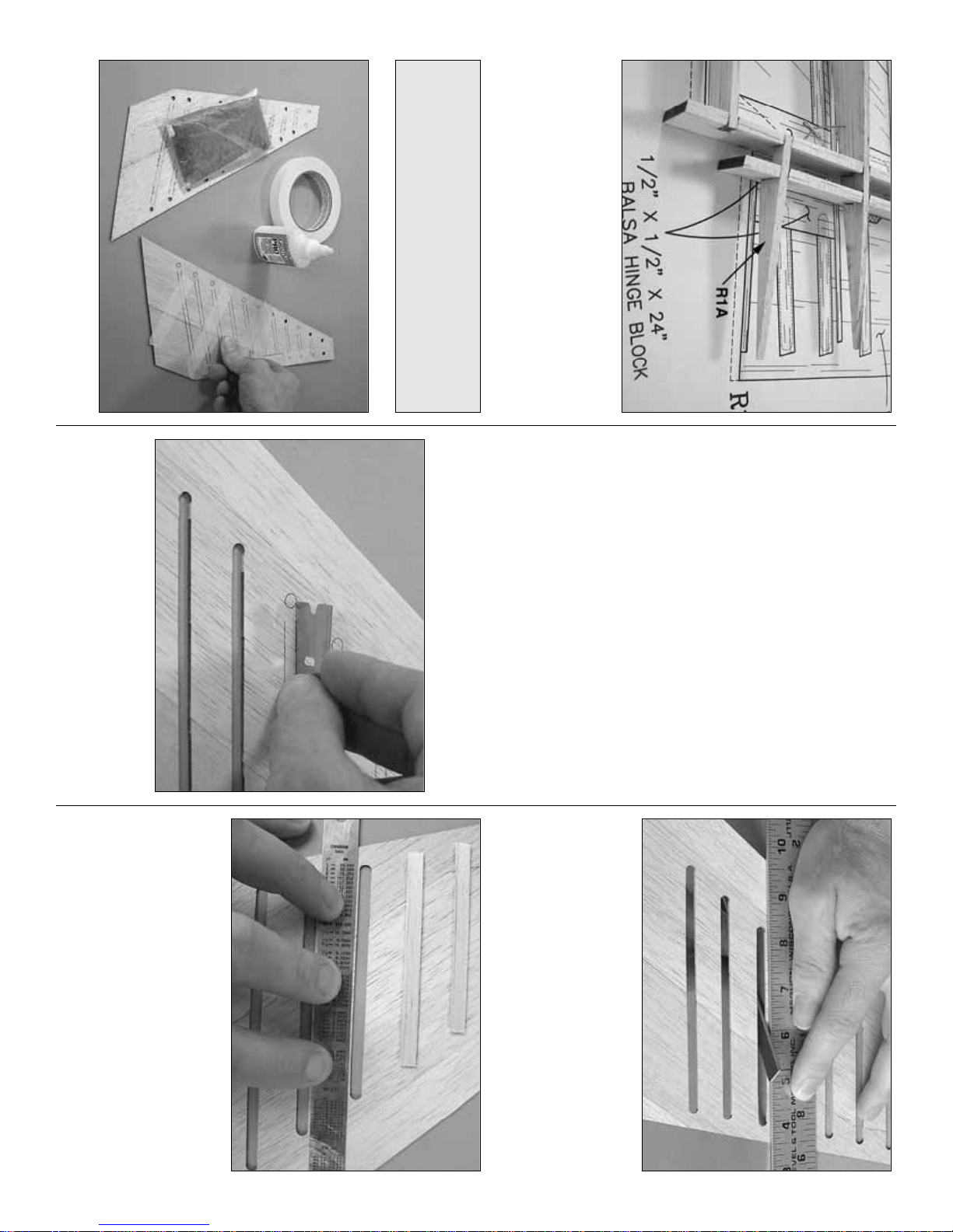
Now it’s time to mak e the balsa skins f or sheeting the
fin and rudder.
❏8. Glue together both sets of die-cut 1/16"[1.6mm]
balsa parts that make up the fin skins. CA could be
used, but aliphatic resin (white glue) is preferred as it
allows time for positioning and is easier to sand.Use
masking tape and weights to hold the parts together
while the glue dries and press down along the glue
joint to make sure the seams are flat.
❏ 9. Cut the two corner pieces and the leading edge
pieces as shown on the plan from a 1/16"x 3"x 30"[1.6 x
75 x 760mm] balsa sheet to complete the skins and glue
them into position.
❏ 10. After the glue dries examine both skins to see
which side will be the right and which side will be the
left.Arrange the skins so the best sides will be on the
outside. Use 180-grit sandpaper to carefully sand
both sides of the skins flat. Note: The insides don’t
have to be as “flat” as the outsides—use care not to
over thin the skins by sanding too much.
❏ 11. Carefully cut out the corr ugations. A single-
edge razor blade works well until you get to the
smaller ones near the top of the skin where a #11
blade will have to be used.
❏ 12. Make a thin sanding tool by using spray
adhesive to bond a piece of medium-grit sandpaper
to a strip of leftover 1/16"[1.6mm] plywood. Use the
sanding tool to true the edges of the corrugations.
Hold the skin down near the edges of the
corrugations with a ruler or something similar so you
do not damage the skin while sanding.
❏ 13. Cut the corrugation filler strips from 1/16"x
1/4"x 30"[1.6 x 6.4 x 760mm] balsa sticks and glue
them to the inside of the fin skins. The best way to
align the strips is with a straightedge—start at the top
and work your way do wn.Once a filler strip has been
positioned, use medium CA to glue it into position.
Using thin CA is not recommended because it may
not create a strong enough bond to hold the filler
strips to the skin when bending it to the ribs.
Note: Should you decide to build your Arrow
without the corrugations, replace the die-cut skins
supplied with this kit with soft to medium density
1/16"[1.6mm] balsa sheeting (not supplied).
- 11 -
Page 12
❏14. Prepare the die-cut 1/16" [1.6mm] balsa rudder
skins by cutting out the corrugations and gluing on the
corrugation fillers the same as the fin skins.
❏ 15. Remove most of the T-pins holding the fin
framework to the building board, but leave a few of
them in R1 and R6 to hold the structure down. Make
sure none of the pins will be concealed under the
skin after it has been glued into position.
Refer to this photo for the following two steps.
❏ 16. Test fit the left fin skin to the framework and
see how it lines up. The bottom of the skin should
align with the dashed line indicating the bottom of the
skin on the plan. After you see how the skin fits, glue
it into position with medium or thick CA.
❏ 17. Glue the left rudder skin into position the
same way.
❏ 18. Take out any remaining T-pins and remove the
fin/rudder assembly from the building board.
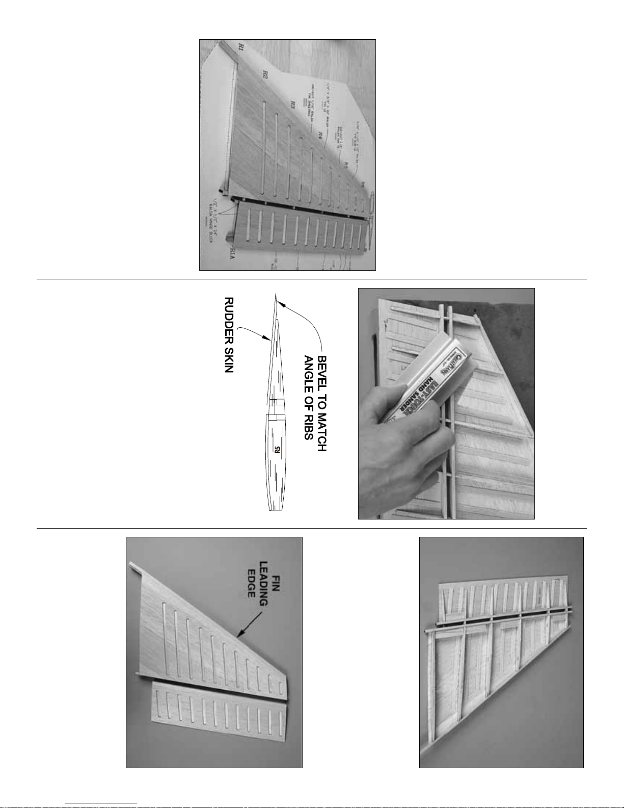
❏19. T rim off the jig tabs with a hobby knif e , then use
a razor plane followed by a bar sander with 80-grit
sandpaper to trim the leading and trailing edges even
with the ribs. Using the ribs in the rudder as a guide,
bevel the trailing edge of the left skin to accommodate
the right skin as shown in the sketch and on the cross
section of the fin drawing on the plan.
❏ 20. Referring to the plan, cut the hinge blocks
from a 1/2"x 1/2"x 24"[12.7 x 12.7 x 610mm] balsa
stick. Trim the blocks so that when in position, they
will be 1/16"[1.6mm] below the surface of the ribs to
accommodate the 1/16"[1.6mm] balsa corrugation
filler strips on the right side of the fin and rudder
skins. Glue the hinge blocks into position.
Refer to this photo for steps 22 through 26.
❏ 21. Test fit, then glue the rudder and fin skin into
position on the right side.Align them the same as was
done for the skins on the left side of the assembly.
❏ 22. Sand the leading edge of the skins even with
the sub leading edge. Trim the bottom of the skins
and the spars even with rib R1 and R1A.
- 12 -
Page 13
❏ 23. Cut the fin leading edge from the 1/4"x 3/4"x
30"[6.4 x 19 x 760mm] balsa stick, then glue it into
position. Save the remainder of the stick for the
rudder leading edge. Sand the top of the fin leading
edge even with R6 and sand the sides of the leading
edge even with both sides of the fin.
❏ 24. Use a small razor saw to separate the rudder
from the fin.Sand the fin sheeting and rib stubs even
with the fin trailing edge and sand the rudder
sheeting and the rib stubs even with the rudder sub
leading edge.
❏ 25. Cut the rudder leading edge from remainder
of the 1/4"x 3/4"[6.4 x 19mm] balsa stick used for the
fin leading edge, then glue it into position. Sand the
top, bottom and sides of the rudder leading edge
even with the rudder, but do not sand the “V” on the
leading edge until instructed to do so.
FINISH THE FIN AND RUDDER
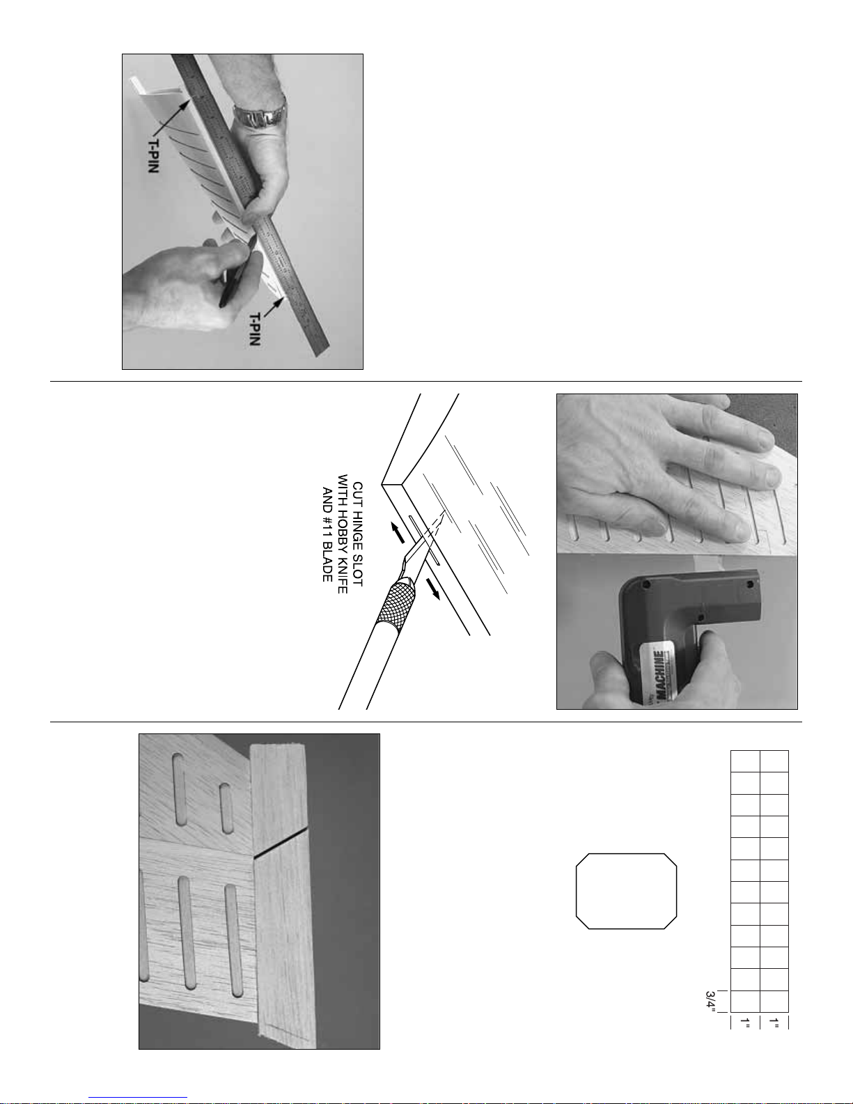
❏ 1. Taking accurate measurements, stick T-pins into
the middle of the fin trailing edge near both ends.Place
a straightedge against the pins and use a fine-point
ballpoint pen to mark a centerline all the way down.
❏ 2. If you have a Great Planes Slot Machine , use it
to cut the hinge slots where shown on the plan on the
centerline you marked. If you do not have a Slot
Machine, use a #11 hobby blade to cut the hinge
slots. Start by making a small slit. Then, working in
small increments, go a little deeper moving the blade
back and forth. Note that it’s the back of the blade
that does the work.
❏ 3. Use the same procedure to mark the centerline
and cut the hinge slots in the rudder.
❏ 4. Cut three 3/4"x 1"[19 x 25mm] hinges from the
CA hinge strip. Snip off the corners so they go in
easier.Temporarily join the rudder to the fin with the
hinges. Use masking tape to securely hold the
rudder to the fin so it will not move.
❏ 5. Cut the fin and rudder tip from a 1/2"x 1"x
24"[13 x 25 x 610mm] balsa stick, then glue them to
the top of the fin and rudder. Be cer tain to leave an
approximately 3/32"[2.4mm] gap between the fin and
rudder tips.
- 13 -
Page 14
❏6. Use a razor plane and/or a hobby knife f ollo wed
by a bar sander to shape the fin and rudder tip to
match the fin and rudder, but do not round the top
until the next step.
❏ 7. Now go ahead and round the tips of the fin and
rudder by sanding.
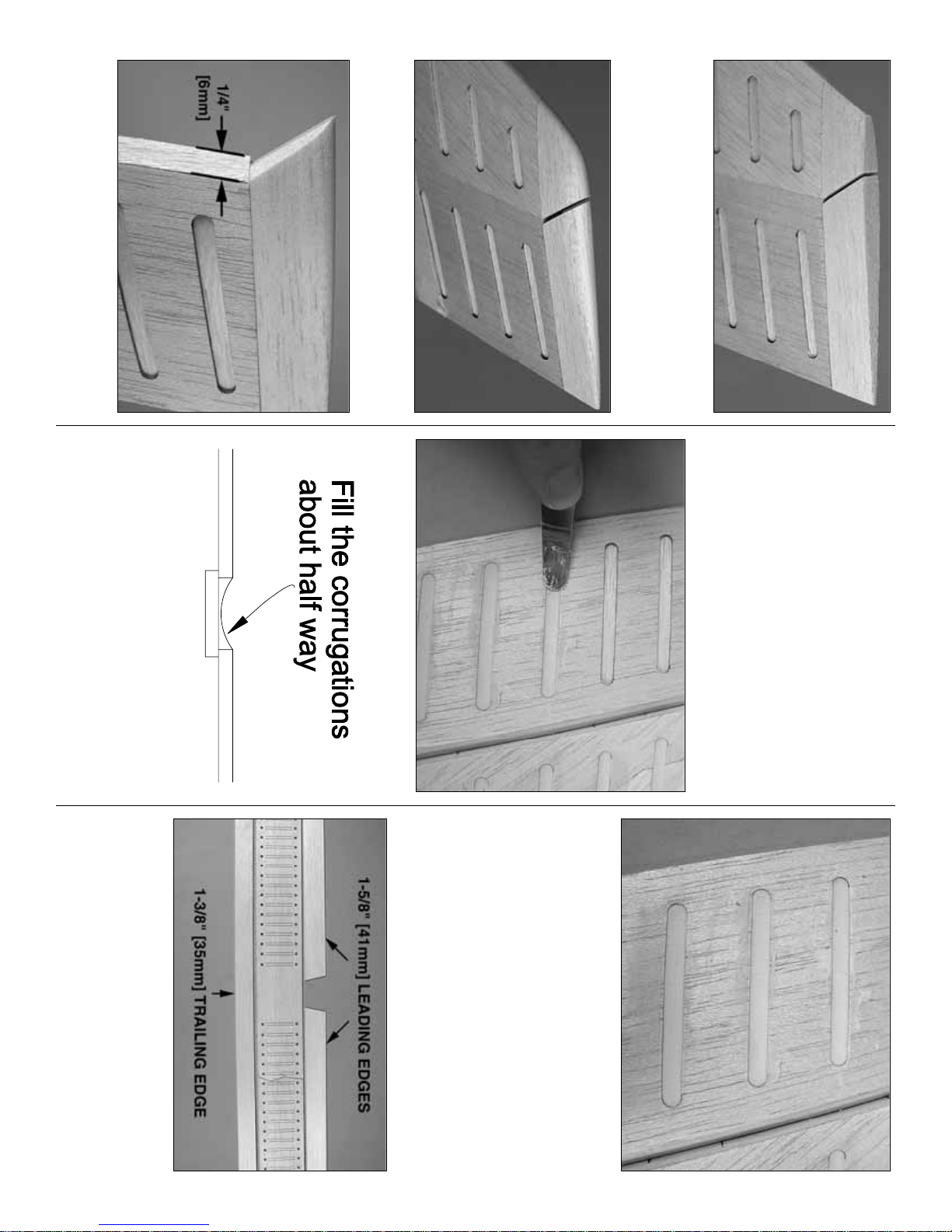
❏ 8. Remove the tape and separate the fin from the
rudder. Use a straightedge and a ballpoint pen to
mark lines on both sides of the rudder 1/4"[6mm]
back from the leading edge. Using the lines and the
centerline as a guide, shape the leading edge of the
rudder to a “V” shape to allow for control throw.Also
shape the front of the rudder tip as shown.
❏ 9. Test fit the rudder to the fin with the hinges.
Move the rudder back and forth to make sure it
moves freely. Make any adjustments necessary.
❏10. Use a putty knife or the included 1/16"[1.6mm]
die-cut plywood applicator to apply lightweight balsa
filler to partially fill the corrugations. Try to be
consistent and fill the corrugations about half-way as
shown in the sketch.
❏ 11. After the filler has dr ied, sand the surface of
the skins and down into the corrugations.
Set the fin and rudder aside while you build the stab.
BUILD THE HORIZONTAL STABILIZER (STAB)
Don’t forget, this is a one-piece, “flying”
stabilizer and has no elevators. Let’s start by
making the top and bottom stab skins…
❏ 1. Cut a 1-3/8"[35mm] strip from a 1/16"x 3"x
30"[1.6 x 75 x 760mm] balsa sheet to be used as the
trailing edge portion of one of the die-cut
1/16"[1.6mm] balsa stab skins. Use the remaining
1-5/8"[41mm] sheet to make the right and left
leading edge portions.
- 14 -
Page 15
❏2. Repeat the previous step to make the leading and
trailing edge portions of the other stab skin. Glue the
sheets you just cut to the front and back of the stab
skins.Reminder: Aliphatic resin is recommended over
CA because it will allow time to position the sheets and
will be easier to sand after it dries.
❏3. While the glue on the stab skins is drying, make
up the ribs for the stab assembly by gluing a die-cut
1/8"[3.2mm] plywood rib doubler “S2C” to both
sides of four die-cut 3/32"[2.4mm] balsa stab ribs
S2. Glue one die-cut 1/8"[3.2mm] plywood rib
doubler “S2B” to one side of another stab rib S2
(make two of these, and be sure to make a right and
a left). Lastly, make two sets of root stab ribs by
gluing together two die-cut 1/8"[3.2mm] plywood
stab ribs S1. Note: If you forget which of the
doublers “B” are, they are the ones with the larger
hole for the brass tubing.
…Back to the stab skins…
❏4. After the glue on the stab skins has dried remove
the masking tape and sand both sides flat and even.
Cut the Stab Center Cutout Template from the plan
and use it to mark the cutout in the stab skins with a
ballpoint pen.Cut and remove the section of sheeting,
but do not cut directly on the line—leave some
additional material to allow for positioning.
❏ 5. Cut out the corrugations and tr ue the edges
with your sanding tool. Cut the corrugation fillers
from more 1/16"x 1/4"x 30"[1.6 x 6 x 760mm] balsa
sticks and glue them to the insides of the stab skins
the same as you did for the fin and rudder skins.
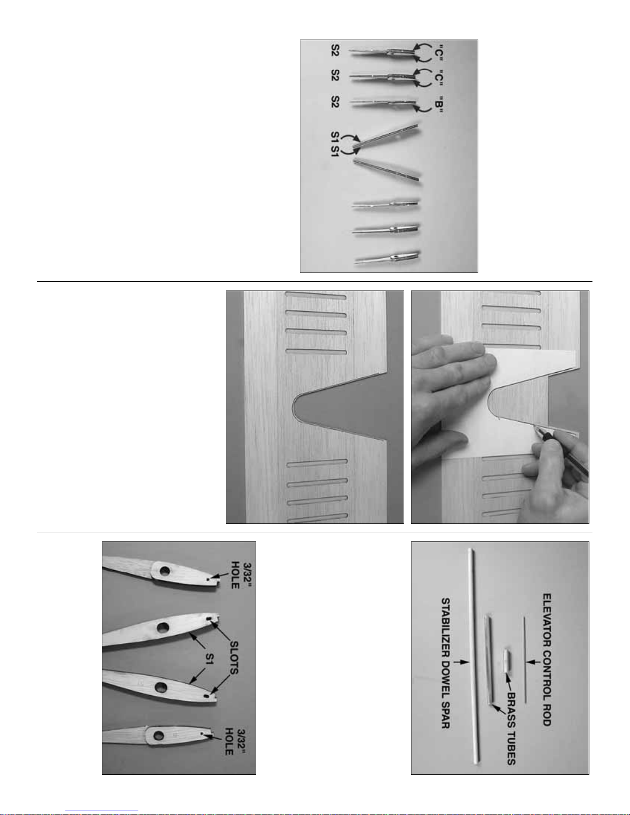
❏ 6. Cut the stabilizer control rod to a length of
6"[150mm] from a 4-40 x 12"[300mm] pushrod by
cutting off the threaded end. Discard the threaded
end (or keep it for your spare parts bin). Cut the
dowel spar to a length of 15-3/4"[400mm] from the
5/16"x 16"[8 x 405mm] hardwood dowel.Use a piece
of a paper towel or a tissue dampened with
denatured alcohol to clean any residual oil from the
control rod. Clean the inside and outside of the
11/32"x 6"[8.7 x 150mm] brass tube and the 3/8"x 1-
1/2"[9.5 x 38mm] brass tube as well.
❏ 7. Drill 3/32"[2.4mm] holes between the ends of
the die-cut slots in the plywood S1 Ribs to make slots
that will accommodate the stabilizer control rod.Also
drill 3/32"[2.4mm] holes through the punchmarks
through the ribs at the punchmarks in the B doublers.
- 15 -
Page 16
❏ 8. Use 320-grit or 400-grit sandpaper to roughen
the outside of the 11/32"x 6"[8.7 x 150mm] brass
tube and the inside and outside of the 3/8"x 1-
1/2"[9.5 x 38mm] brass tube so glue will adhere.
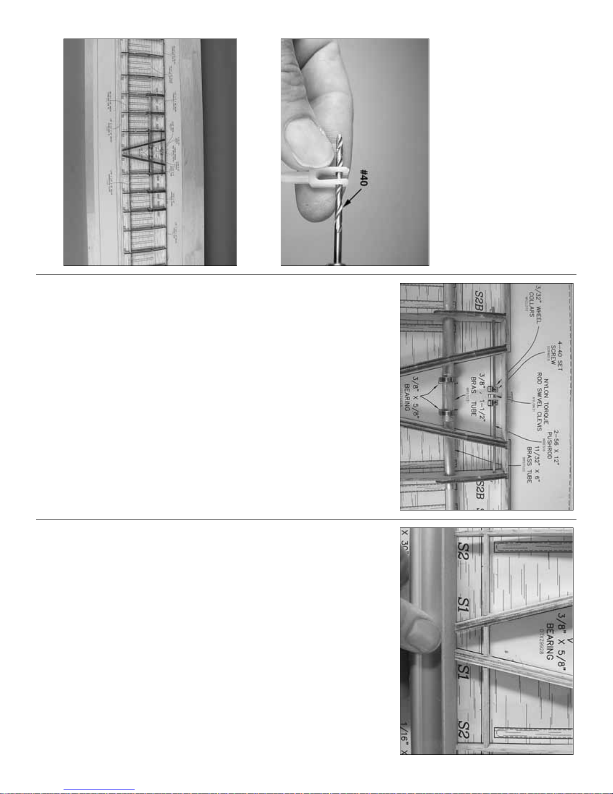
❏ 9. Use 30-minute epoxy to glue the dowel spar
and tubes together—both tubes should be centered
on the dowel. From now on this assembly will be
referred to as the stab spar.
Note: It may be necessary to sand down the dowel
to get it to fit into the 11/32" [8.7mm] brass tub.
❏ 10. Enlarge the holes in the nylon swivel clevis
with a #40 drill.
❏ 11. Slide the swivel clevis and two 3/32"[2.4mm]
wheel collars onto the 4-40 control rod. (The set
screws will be installed and tightened when finalizing
the radio setup after the model has been completed.)
Slide the bearings over the stab spar. Fit the ribs on
the pushrod and the stab spar.Working over the stab
plan, fit the assembly to the die-cut 3/32"[2.4mm]
balsa sub leading edge and the die-cut
3/32"[2.4mm] balsa sub trailing edge. Join the rest
of the ribs to the assembly.
❏ 12. Hold the stab assembly to the building board
with T-pins.Glue the ribs to the sub leading edge and
to the sub trailing edge.
❏ 13. Securely glue the stab spar and the stabilizer
control rod to the ribs.
❏ 14. Use a razor plane followed by a bar sander to
shape the top of the sub leading and trailing edges
even with the tops of the ribs to accommodate the
sheeting. Make sure none of the T-pins are in the way.
❏ 15. Sand the trailing edge of the plywood S1 ribs
to accommodate the balsa stab trailing edge.
❏ 16. Remove any T-pins from the stabilizer
assembly that will be concealed under the stab skin
when you glue it into position. Glue one of the stab
skins to the top of the stab. Thick or medium CA
could be used, but aliphatic resin is recommended
because it will allow more working time for
positioning the skin. Use T-pins and weights to
securely hold the skin down until the glue dries.
❏ 17. Remove the stab from the building board.The
same as you did with the vertical stabilizer, trim the
bottom of the sub trailing edge and the bottom of the
sub leading edge even with the ribs to accommodate
the bottom sheeting.
- 16 -
Page 17
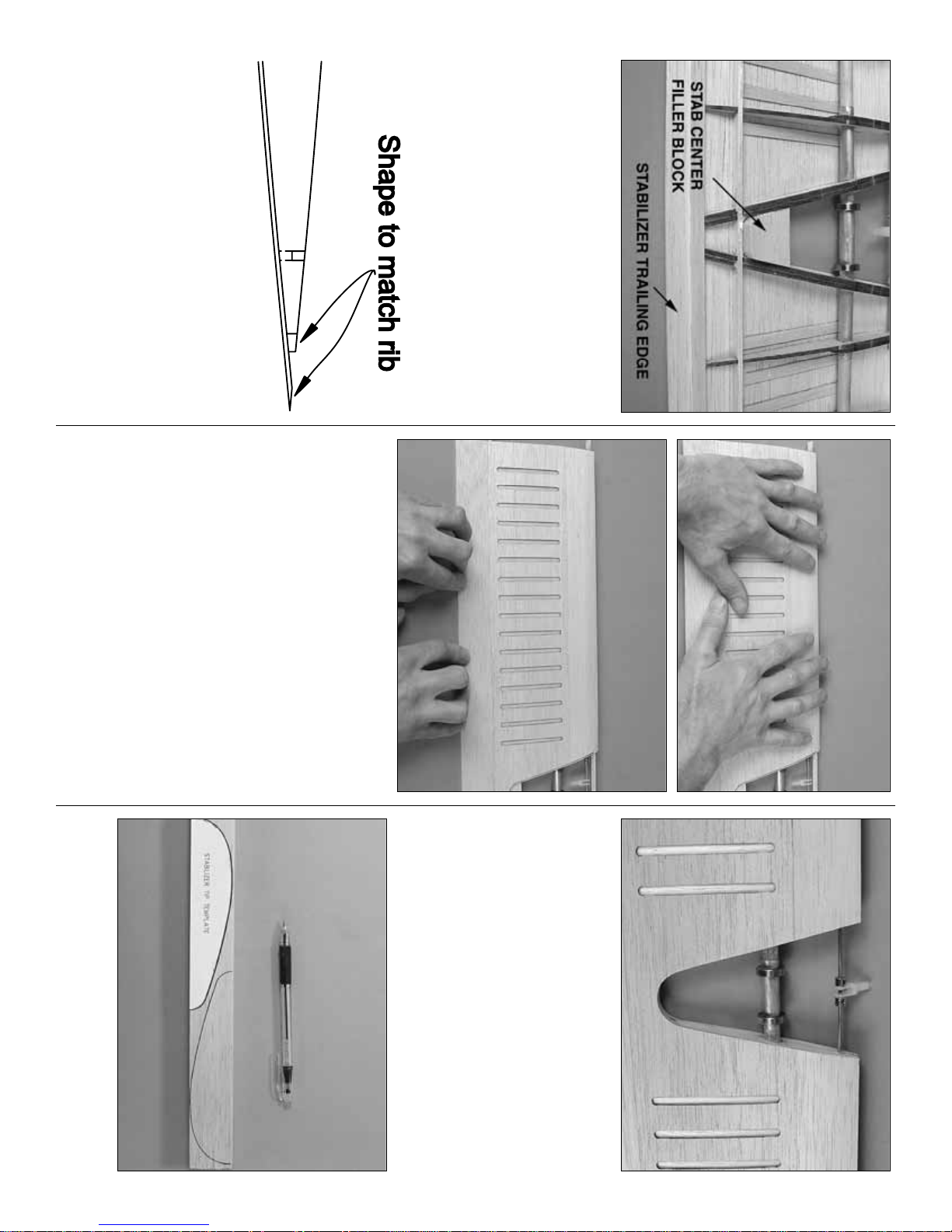
❏ 18. Glue the 1/8"x 1/4"x 30"[3.2 x 6.4 x 760mm]
balsa stabilizer trailing edge into position. Cut the
stab center filler block from the 1/2"x 1"x 24"[12.7
x 25 x 610mm] balsa stick (first used for the fin and
rudder tips). Shape the block to fit between the S1
ribs, but don’t worry about rounding the inside edge
at this time. Glue the block into position.
❏ 19. Shape the stabilizer trailing edge, the stab
center filler block and the top sheeting to match the
shape of the ribs.
❏ 20. Prepare to glue on the bottom stab skin.Test
fit the skin and check the alignment. Make any
adjustments where necessary for a good fit.The skin
will be glued on with medium or thick CA, so you’ll
want to get it positioned correctly and work quickly.
❏ 21. Apply thick or medium CA to the ribs and
spars and to the trailing edge of the top skin where it
contacts the bottom skin. Working quickly, position
the bottom skin.Carefully press the skin into position
without introducing any twist. Apply pressure to the
trailing edge over your flat work surface. This will
ensure a straight and true trailing edge. Handle both
halves of the stab as though they were two separate
pieces—work on pressing down both halves of the
skin separately.
❏ 22. After the CA has hardened, trim the leading
edge and the tips of the skins even with the sub
leading edge and the ribs.
❏ 23. Round the stab center filler block and trim the
sheeting even with the S1 ribs.
❏ 24. Cut the stabilizer leading edge from a 1/4"x
1/2"x 30"[6.4 x 25 x 760mm] balsa stick, then glue it
into position. Shape the leading edge to match the
plan and sand it even with the tip ribs and the S1 ribs.
❏ 25. Cut the Stabilizer Tip T emplate from the plan
and use it to cut out two stabilizer tips from the 1"x
1-1/2"x 15"[25 x 38 x 380mm] balsa stick.
- 17 -
Page 18
❏ 26. Mark a centerline around the tips, then glue
them into position. Using the centerlines as guides,
carve and sand the tips to match the stab, then round
to a finished shape.
❏ 27. The same as was done on the fin and rudder
corrugations, get out your putty knife and wood filler
and partially fill all of the corrugations on both sides
of the stab.Allow to dry, then sand.
BUILD THE WING
MAKE THE WING SKINS
❏ 1. Cut the wing center panel plan from the wing
plan.Cover the plan with Plan Protector or w ax paper
and place it over your flat building board.
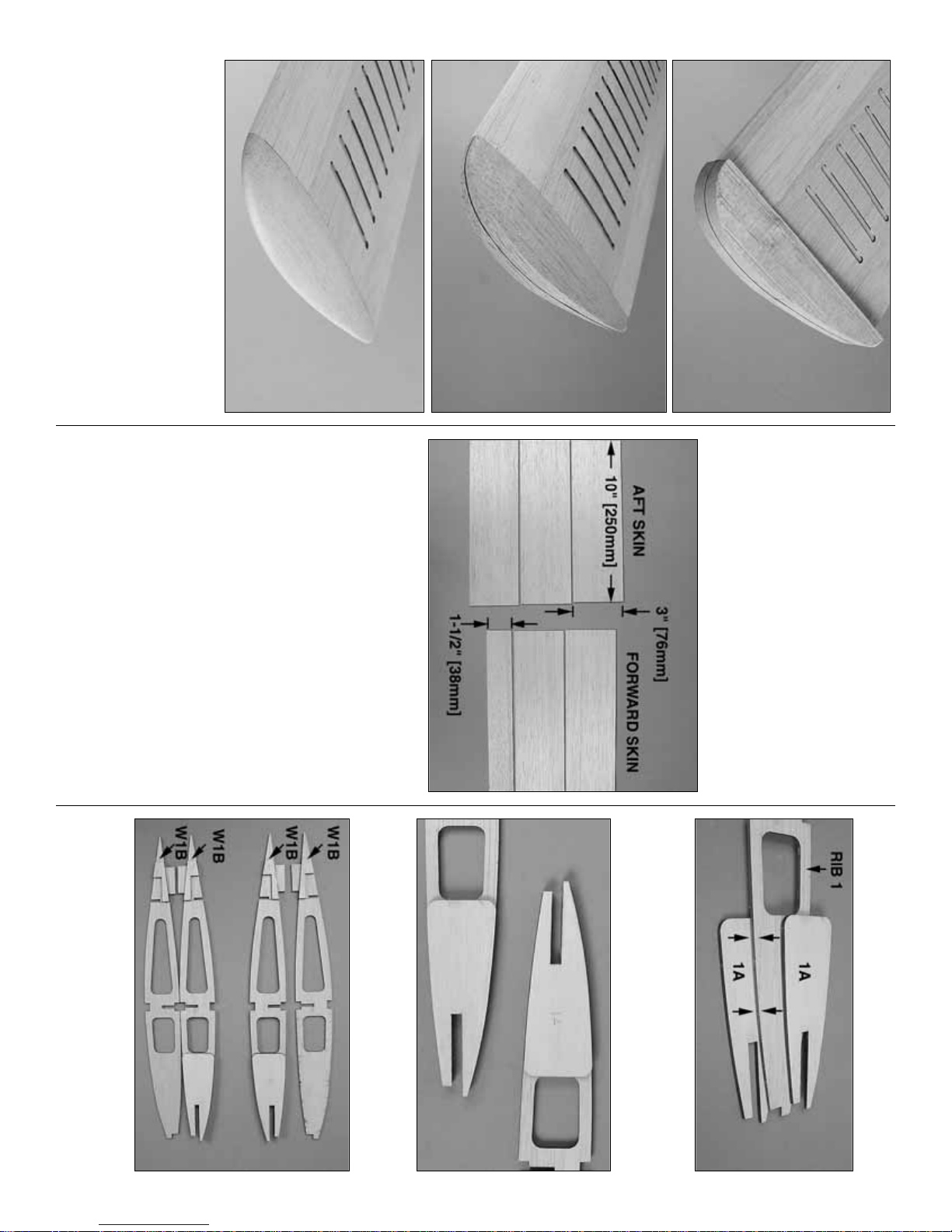
❏ 2. Cut four 1/16"x 3"x 30"[1.6 x 75 x 760mm] balsa
sheets into twelve 3"x 10"[75 x 250mm] balsa sheets.
Set one of the 3"x 10"[75 x 250mm] sheets in your scrap
pile and cut another one of the 3"x 10"[75 x 250mm]
sheets into two 1-1/2"x 10"[38 x 250mm] sheets.
❏ 3. Glue the sheets together as shown in the
previous photo to make a forward and aft center
panel skin. Make two of each.
❏ 4. Sand the skins flat and even.
BUILD THE CENTER PANEL
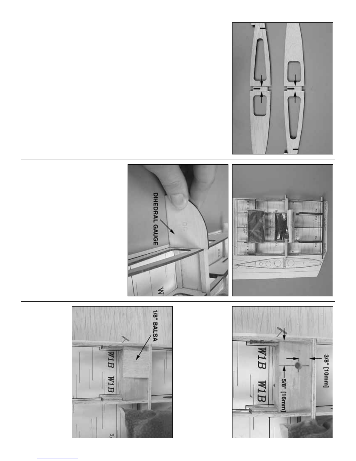
❏ 1. Glue a die-cut 1/8"[3.2mm] plywood rib
doubler 1A to both sides of a die-cut 3/32"[2.4mm]
balsa rib W1.Make another assembly the same way.
❏ 2. Cut the balsa from between the dowel notches
in both rib assemblies.
❏ 3. Referring to the plan, glue the four die-cut
1/8"[3.2mm] plywood doublers W1B to the opposing
sides of the outer two ribs that will go on both ends
of the center panel.
- 18 -
Page 19
❏ 4. Use a #11 blade to cut part way through both
sides of the ribs that go on the outer ends of the
center panel between the spar notches.
❏ 5. Glue together both die-cut 1/8"[3.2mm]
plywood center leading edges (CLE).
❏ 6. Cut the top and bottom spars for the center
panel to a length of 9-3/8"[240mm] from a 1/4"x 3/8"x
36"[6.4 x 9.5 x 910mm] basswood stick.
❏7. Join the ribs to the center leading edge, the die-
cut 1/8"[3.2mm] plywood center trailing edge, the
die-cut 1/8"[3.2mm] plywood center spar web and
the top and bottom main spars.
❏ 8. Position the assembly over the plan and hold it
down with weights and a few T-pins stuck into the jig
tabs and into the bottom of the ribs where they
contact the plan, just aft of the bottom spar.Use thin
and medium CA to glue all the parts together.When
gluing the outer ribs, use the die-cut 1/8"[3.2mm]
plywood dihedral gauge to make certain they are
set at the correct angle.
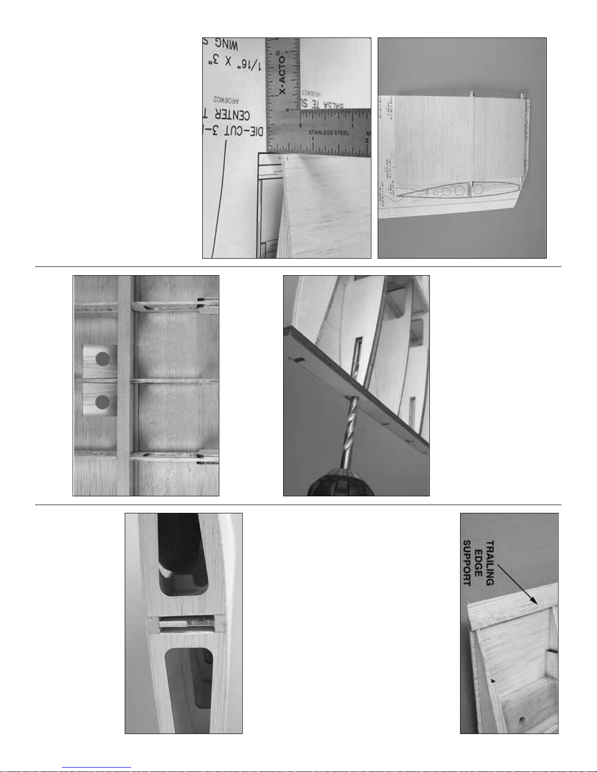
❏ 9. Mark the center of the hole to be drilled in one
of the 3/8"x 1"x 2-1/16"[9.5 x 25 x 52mm] basswood
wing bolt blocks 5/8"[16mm] from the end and
3/8"[10mm] from the front edge. Drill a #7 hole
through the block at the mark. Mark and drill the
other wing bolt block the same way. Use 30-minute
epoxy to glue the wing bolt blocks into position.
❏ 10. After the epoxy hardens, glue leftover
1/8"[3.2mm] balsa over the blocks to support the
sheeting around the holes that will be drilled later.
❏ 11. Remove the weights and carefully sand the
tops of the center leading edges and the center
trailing edge even with the tops of the ribs.
- 19 -
Page 20
Refer to this photo for the following two steps.
❏ 12. Both sides of the center panel will be sheeted
in two sections—with the seam centered over the
main spars. With the assembly accurately aligned
over the plan, start by sheeting the aft section with
one of the skins you prepared earlier. The skin
should be trimmed so that the aft edge aligns with
the trailing edge depicted on the plan and the front
edge aligns with the middle of the top spar.Glue the
skin into position—aliphatic resin is preferred as it
will allow time for alignment. Thick or medium CA
could be used, but you’ll have to work quickly.
❏ 13. Glue the forward sheet into position.
❏ 14. After the glue has dried, remove the center
panel plan from the building board. Carefully cut the
jig tabs from the bottom of the ribs.Sand all the parts
even with the ribs and bevel the underside of the
trailing edge of the top sheeting to the same angle as
the ribs to accommodate the bottom sheeting.
❏ 15. Using the holes in the wing bolt blocks as a
guide, drill a #7 hole through the top sheeting.
❏ 16. Drill 1/16"[1.6mm] pilot holes through both
punchmarks in the center leading edge. Enlarge the
holes for the wing dowels with a 1/4"[6.4mm] drill.
❏ 17. Glue pieces of leftover 3/32"[2.4mm] balsa
inside the wing where shown.Cut or drill 1/2"[13mm]
holes for the servo wires and air lines.
❏ 18. Cut the trailing edg e support from a 1/8"x
1/4"x 30"[3.2 x 6.4 x 760mm] balsa stick and glue it
into position.Bevel the support to match the shape of
the bottom of the wing.
❏ 19. Select the hardest of the remaining 1/16"x 3"x
30"[1.6 x 75 x 760mm] balsa sheets.F rom this sheet,
cut the shear webs as shown on the plan for the
front and back of the spars on both ends of the panel.
Glue the webs into position.
❏ 20. Sheet the bottom of the center panel in two
sections the same way you sheeted the top.
❏ 21. Trim the sheeting and spars even with the ribs
on both ends of the center panel. Sand the sheeting
flat and even.
❏ 22. Remember when you were instructed to cut
part way through the ribs on the ends of the panel?
Now is the time to cut the rest of the way through the
ribs along the lines and remove the material between
the spars.
Now the center panel is complete and may be set
aside while building the outer panels.
- 20 -
Page 21
BUILD THE OUTER PANELS
We’ll start by making the wing skins. It’s a bit of an
undertaking to do them all at once, but then you
won’t have to make any more. Or you could just
make the skins as needed…
❏ 1. Glue together two 1/16"x 3"x 36"[1.6 x 75 x
910mm] balsa sheets to make one 6"x 36"[150 x
910mm] balsa outer wing skin. Make seven more
6"x 36"[150 x 910mm] outer skins the same way.
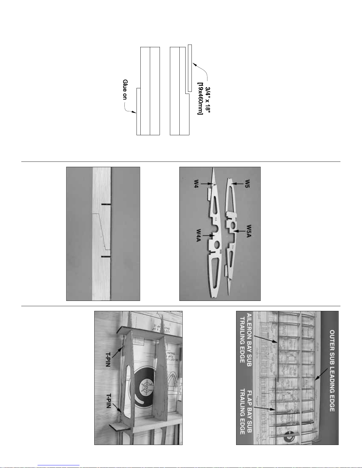
❏ 2. After the glue has dried, cut a 3/4" x 18"[19 x
460mm] strip from four of the skins.These will be the
skins used for sheeting the front of the wings. Glue
the cut off strips to each of the remaining four other
skins. These will be the skins used for sheeting the
rear of the wings.
❏ 3. After the glue has dried, sand the skins flat.
Remember, the insides of the skins don’t have to be
perfect—do not ov er thin the skins by sanding too much.
Start building the left panel so your progress
matches the photos the first time through.
❏❏4. Cut the left wing panel plan from the wing
plan and place it over your flat building board and
cover with Plan Protector so glue will not adhere.
❏❏5. The same as was done for the ribs on the
ends of the center panel, cut partway through both
sides of rib W2 between the spar notches.
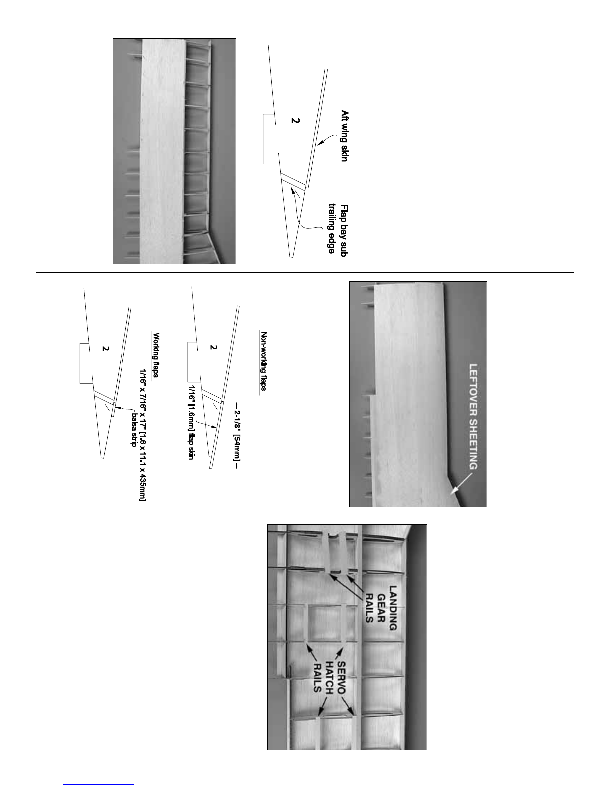
❏❏6. Glue a die-cut 1/8"[3.2mm] plywood wing rib
W5A to W5 and glue a W4A to W4. Make sure you
glue the “A” ribs to the correct side for the wing
panel you are working on.
❏❏7. Glue together the two parts of the die-cut
1/8"[3.2mm] plywood spar webs.
❏❏8. Cut two 1/4"x 3/8"x 36"[6.4 x 9.5 x 910mm]
basswood sticks to the length shown on the plan for
the top and bottom spars.
❏❏9. Fit but do not glue all the wing ribs (W2
through W9) to the spar web. Fit but do not glue the
top and bottom spars, the die-cut 1/8"[2.4mm] balsa
aileron bay sub trailing edge, flap bay trailing
edge and the die-cut 3/32"[2.4mm] balsa outer sub
leading edge.
❏❏10. Pin five or six of the wing ribs down to the
building board through the low points just aft of the
bottom spar and through the jig tabs.
❏❏11. Use thin or medium CA to glue all
contacting parts together except for the top spar—do
not get any glue on the top spar. Use the dihedral
gauge to make sure rib W2 is set at the correct
angle. (The rib should lean slightly toward the wing
tip to accommodate the dihedral.)
- 21 -
Page 22
❏❏12. Remove the top spar from the assembly.
Apply a bead of medium or thick CA along the top
edge of the spar web, then reposition the top spar.
Make sure W2 is still at the correct angle using the
dihedral gauge.
❏❏13. Glue the die-cut 1/8" [3.2mm] balsa inner
sub leading edge into position.
❏❏14. Prepare the top of the wing for sheeting by
trimming and sanding the sub leading edges, the
aileron bay sub trailing edge, the flap bay trailing
edge and the top spar even with the tops of the ribs.
❏❏15. Trim one of the aft skins to fit the wing so
that the front edge aligns with the middle of the top
spar and the aft edge aligns with the middle of the
flap bay sub trailing edge. The skin should extend
1/16" [1.6mm] or so past the aileron bay sub trailing
edge to allow for trimming later.
❏❏16.Glue the aft skin into position.Aliphatic resin is
recommended as it will allow time for positioning. Use
weights and T-pins to hold the skin in position while the
glue dries.The rest of the trailing edge betw een the W9
ribs at the wing tip will be sheeted later.
Refer to this photo for the following two steps.
❏❏17. Cut and trim one of the forward skins to fit
the wing, then glue it into position. Use a piece of
leftover sheeting for the small cor ner at the leading
edge where the front sheet won’t reach.Use weights
and/or T-pins to hold the sheeting down while the
glue dries.
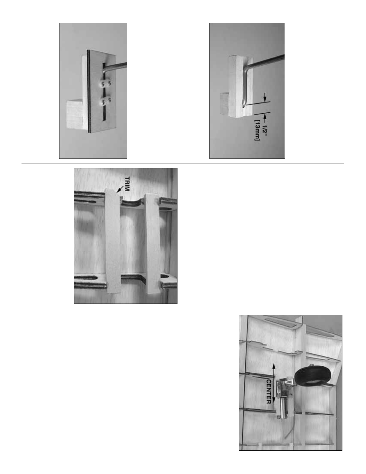
❏❏18. If not building flaps, test fit one of the die-cut
1/16" [1.6mm] balsa flap skins to the wing.The trailing
edge of the skin should extend 2-1/8" [54mm] aft of the
top wing skin.Cut out the slots for the corrugations and
trim the flap skin as necessary for a good fit, then glue
the skin into position. If you are building working flaps,
trim a 7/16" x 17-3/4" [11 x 435mm] strip from a piece
of leftover 1/16" [1.6mm] hard balsa.Glue the strip over
the flap bay trailing edge.
❏❏19.After the glue on all of the wing sheeting has
dried, remove the wing from the building board.
Refer to this photo for the following two steps.
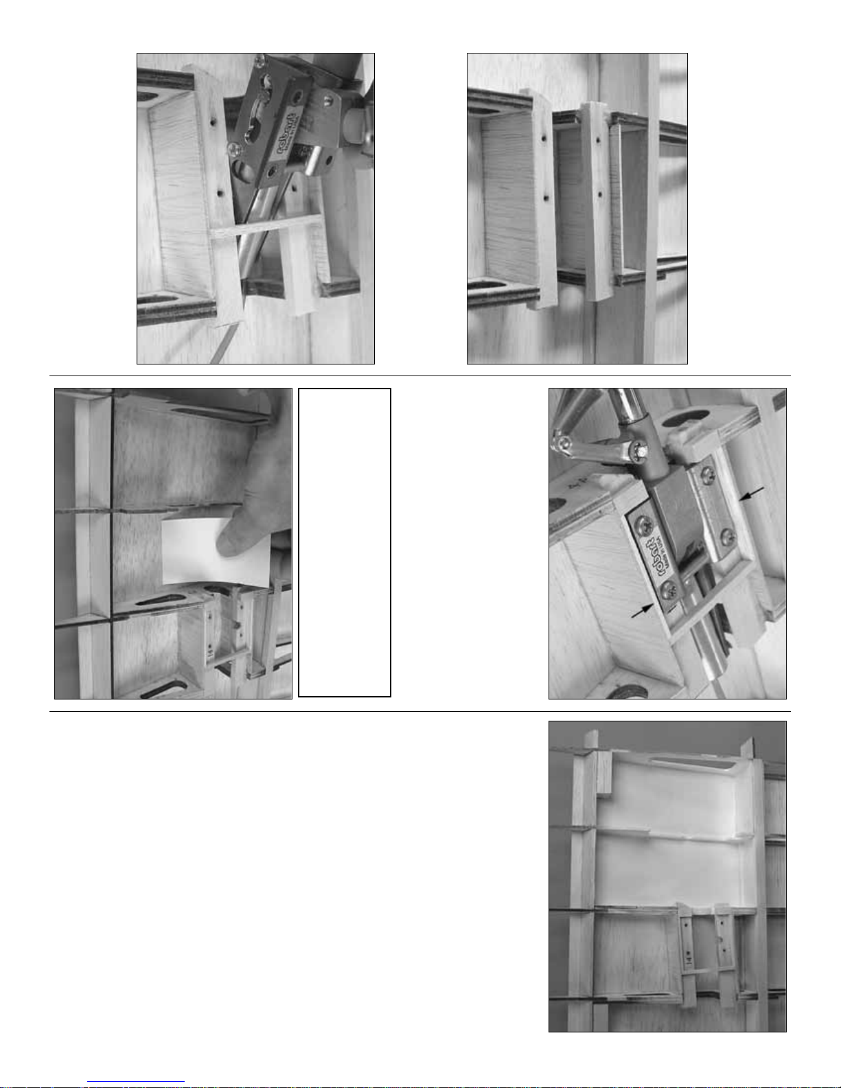
❏❏20. Flip the wing over and lay it on your
workbench. Cut two 3-3/4" [95mm] long landing
gear rails from the 1/4" x 1/2" x 16" [6.4 x 13 x
410mm] basswood stick. Use 30-minute epoxy to
glue the rails into position. For additional strength,
milled glass fibers could be added to the mixture.
This will allow you to build up small fillets without the
glue dripping away from the joints.
❏❏21. While the epoxy on the landing gear rails is
hardening, make the servo hatch rails from a 1/4" x
3/8" x 36" [6.4 x 9.5 x 910mm] basswood stick and glue
them into position. Be certain to glue the aileron hatch
rails in the two inboard W8 ribs as shown on the plan.
Note: If not building working flaps, there is no need to
cut and glue in the servo rails for the flaps.
❏22. Return to step 4 and build the right wing panel.
Don't forget to build over the right wing plan.
- 22 -
Page 23
FIT THE FIXED LANDING GEAR
Skip this section if installing retracts.
Note: Even though the landing gear assembly for the
left wing is shown in the photographs, both landing
gear assemblies could be installed simultaneously.
❏ 1. Use 30-minute epoxy to glue a 3/4" x 1" x 1" [19
x 25 x 25mm] basswood main landing gear torque
block to one end of a 1/2" x 1" x 2-11/16" [12.7 x 25
x 68mm] grooved bass w ood main landing gear rail.
After the epoxy has hardened drill a #11 (or 3/16"
[4.8mm]) hole in the middle of the groove through the
rail and the block 1/2" [13mm] from the end. Bevel
the opening of the hole to accommodate the bend in
the wire, then test fit the left landing gear wire.
Refer to this photo for the following two steps.
❏ 2. Glue together two die-cut 1/16" [1.6mm] plywood
fixed landing gear plates.Note that the grain direction
of each plate runs in the opposite direction. Use 30-
minute epoxy to glue the plates to the rail, but use care
not to inadvertently glue in the wire gear.
❏ 3. Secure the gear with two nylon landing gear
straps and four #2 x 1/2" [13mm] screws. Drill 1/16"
[1.6mm] holes for the screws.Don’t forget to harden
the threads with a few drops of thin CA.
❏ 4. Install the assembly in the wing between the
landing gear rails, then drill six 7/64" [2.8mm] holes
through the landing gear plates and the rails in the
wing for the mounting screws. Remove the landing
gear from the wing and enlarge the holes in the
landing gear plate with a 9/64" [3.6mm] or 5/32"
[4mm] drill. Mount the landing gear assembly to the
wing with six #6 x 1/2" [13mm] screws.
FIT THE RETRACTABLE LANDING GEAR
Skip this section if installing fixed landing gear.
❏ 1. Remove the partial cutout in rib 3 to
accommodate the wheel.
❏ 2.Test fit the landing gear into the rail. If the fitting
for the air line on the side of the air cylinder prevents
fitting the retract, the cylinder may be rotated so the
fitting is facing at a downward angle.Then the retract
unit should fit between the rails.A small corner of the
aft rail will have to be trimmed to accommodate the
oleo strut.
❏ 3. Center the landing gear in the rails from side-to-
side. Mark the center of the four mounting holes on
the rail. Drill 7/64" [6.7mm] holes through the rails at
the marks for the mounting screws.Mount the retract
to the rail with the #6 x 1/2" [13mm] screws that
came with the retract.
❏ 4. Fit a piece of 3/16" [4.8mm] brass tubing into
the strut where the axle goes. Place a straightedge
on the wing parallel with the spar.Adjust the strut so
the tubing is parallel with the straightedge and
tighten the strut.
❏ 5. Cut the axle to the correct length and mount a
3" [75mm] wheel to the strut.
❏ 6. Retract the gear into the wing. Trim rib R3 as
necessary so the wheel will fully retract.
❏ 7. Remove the retract unit from the wing. Add
several drops of thin CA to the scre w holes to harden
the threads.
- 23 -
Page 24
FINISH FITTING THE LANDING GEAR
Even though retractable landing gear are shown
in the photos, this section applies both to fixed
and retractable landing gear.
❏ 1. Cut the landing gear rail shear webs from the
remainder of the 1/16" x 3" x 30" [1.6 x 75 x 760mm]
balsa sheet used for the shear webs for the center
panel. Glue the shear webs into position.
❏ 2. Deter mine how close you can position a piece
of leftover 1/8" [3.2mm] balsa across the rails to the
retract unit while still allowing the unit to be removed
from the wing. This piece of balsa will support the
sheeting. Glue the suppor t into position.
❏ 3. Build a
box
around the retract mount with
leftover balsa strips.Sand the edges of the box even
with the contour of the ribs. After the bottom of the
wing has been sheeted and the opening has been
cut for the retract, the opening will be nice and neat
and the sheeting will be supported.
❏ 4. Optional: For a durable, finished appearance,
the top sheeting inside the wing over the wheel
openings can be coated with lightweight (3/4 oz.)
fiberglass cloth and resin.When sanded and painted,
this will make the inside of the wheel wells fuel and
weather proof and look great. First, cut four strips of
cloth (two for each wing) to fit between the ribs, then
lay into place.Use a soft brush to coat the cloth with
finishing resin or 30-minute epoxy. Before it thickens,
use a business card to lightly squeegee excess resin
from the cloth.This will remove wrinkles and bubbles
making the cloth lay flat. After the epoxy has fully
hardened, lightly sand with 400-grit sandpaper. Now
the wheel wells may be painted. An airbrush will
provide the most ev en coverage and allow you to get
paint into all of the little corners without over spraying
the rest. See page 61 on how to spray LustreKote
®
through an airbrush. Note: Should you decide to add
the cloth later, be certain to do so BEFORE covering
the model. Otherwise, epoxy and paint will soak into
the sheeting and show through the covering.
If you will be “glassing”and painting the inside of
the wheel wells, get the other wing panel to this
same stage of completion. That way both wheel
wells can be treated at the same time.
- 24 -
Page 25

SHEET THE BOTTOM OF THE WING
❏ 1. Trim the jig tabs from the ribs on the bottom of
the wing. Sand the flap bay trailing edge, the aileron
bay sub trailing edge and the sub leading edges
even with the bottoms of the ribs.
❏ 2. If not building working flaps, cut out the
corrugations from a die-cut 1/16" [1.6mm] balsa flap
skin. Glue the flap skin to the wing, then glue on the
1/8" x 1/4" x 30" [3.2 x 6.4 x 760mm] balsa TE
support and the corrugation filler str ips. Use the ribs
on the bottom of the wing as a guide to sand the TE
support and the top flap skin to accommodate the
bottom flap skin.
❏3. If building working flaps, cut three 1-1/2" [40mm]
flap hinge blocks from the 3/4" x 3/4" x 12" [19 x 19
x 300mm] balsa stick. Shape the hinge blocks to fit
the flap bay trailing edge, then glue them into
position where shown on the plan. Sand the hinge
blocks even with the bottom of the wing.
❏ 4. If building working flaps, trim the ribs and top
sheeting aft of the flap bay trailing edge as shown.
❏ 5. Assemble the three die-cut 1/8" [3.2mm] plywood
wing cradles by gluing the “feet” onto the supports.
❏6. Use thick or medium CA to tack glue the cradles
to the top wing sheeting directly over the respective
ribs—just a drop of CA in a few areas is all that is
required.
❏ 7. Use leftover 1/16" [1.6mm] sheeting and a
leftover 1/8" x 1/4" [3.2 x 6.4mm] balsa stick to sheet
the top of the wing and the TE support over the R9
ribs at the wing tip. Sand the sheeting and TE
support even with the bottom of the ribs.
❏ 8.T rim one of the aft wing skins to fit the bottom of
the wing. If building flaps, the skin should extend
slightly beyond the flap ba y trailing edge for trimming
later. If building fixed flaps the skin should extend
only to the middle of the flap bay trailing edge. In
both cases, the front of the skin should align with the
middle of the bottom spar.Glue the skin into position,
but do not glue the skin to the flap or aileron hatch
rails or to the ribs between the rails.This will facilitate
the cutting of the sheeting for the hatch covers later.
Glue another piece of leftover 1/16" [1.6mm]
sheeting to the bottom of the wing over the R9 ribs.
❏ 9. If building fixed flaps glue the corrugations to
the inside of another flap skin, test fit, then glue the
skin into position.
❏10. Fit, then glue the forward wing skin into position.
- 25 -
Page 26

MOUNT THE HATCHES AND LANDING GEAR
❏ 1. Cut the openings for the aileron and flap (if
used) hatches. Start by cutting a small hole, then
enlarging the hole until you get to the ribs and the
servo rails. Use the die-cut 1/16" [1.6mm] plywood
hatches as templates to enlarge the openings until
the hatches fit perfectly (with an approximately 1/64"
[.5mm] gap all the way around). Note that the ribs
support both the sheeting and the hatch, so you’ll
have to work with precision.
❏ 2. Center the hatch in the opening. Hold the hatch
down so it will not move, then drill 1/16" [1.6mm]
holes through the hatch and the mounting rails.
❏ 3. Remove the hatch. Enlarge the holes in the
hatch only with a 3/32" [2.4mm] drill. Countersink
the holes in the hatch with a small countersink, a
hobby knife or a Dremel #178 cutting bit (shown in
the photo).
❏ 4. Mount the hatch to the wing with four #2 x 3/8"
[9.5mm] screws. If necessary, perfect the gap all the
way around the hatch by trimming the hatch or the
opening. Remove the hatch, then use medium CA to
glue the sheeting to the ribs and rails where it wasn’t
glued before.
- 26 -
Page 27

❏ 5. Cut the sheeting for the landing gear and the
wheels (if installing retracts). Do it the same way you
did for the servo hatches—start by cutting small
holes, then enlarging the holes until you can get the
gear and the wheel to fit. If installing retracts, mount
the gear first, then cut the hole for the wheel as you
retract the gear and fit the wheel into the wing.
❏ 6. If you mounted retracts, reinforce the bottom
sheeting around the wheel cutouts with 1/32" [.8mm]
plywood (not included) or 1/16" [1.6mm] balsa.Do so
first by cutting a sheet to fit between the ribs, then by
marking the cutout. Cut out the unneeded portion,
then use medium CA to glue the sheet into position.
Do this in sections until the opening is completely
lined. True the edges to match the shape of the
original cutout.
❏ 7. True all the edges of sheeting and spars even
with both ends of the wing, the sub leading edges,
the aileron bay sub trailing edge and the flap bay
trailing edge.
❏ 8. Cut the aileron bay trailing edge from a 3/8" x
1" x 18" [9.5 x 25 x 460mm] balsa stick, then glue it
into position. Car ve and sand to match the wing.
❏ 9.The same as was done for the ribs on the ends
of the center panel, cut the rest of the way through
the rib on the end of the outer panel so the spar
joiner will fit in the wing.
❏ 10. Cut the outer leading edge from a 3/8" x 7/8"
x 30" [9.5 x 22.2 x 760mm] balsa stick, then glue it to
the front of the wing. Cut the inner leading edge
from another 3/8" x 7/8" x 30" 9.5 x 22.2 x 760mm]
balsa stick and bevel the end to meet the outer LE.
Glue the inner LE into position. Shape the leading
edges to match the wing, but don’t round and final-
shape them yet.
❏ 11. Use the wing tip template on the plan to
shape one of the 2" x 2" x 13" [50 x 50 x 330mm]
balsa blocks.Glue the block to the end of the wing.
- 27 -
Page 28

❏ 12. Use a carving knife or a razor plane to shape
the top of the block to match the shape of the wing.
Follow with a bar sander and 80-grit sandpaper.
Note: When sanding, hold the bar sander on the end
over the tip and apply pressure there only. This way,
you won’t be sanding the sheeting.
❏ 13. Shape the bottom of the tip to a 45-degree
angle as shown on the cross-section on the plan.
❏14. Use progressively finer grades of sandpaper to
final-shape the wing tip and the leading edge of
the wing.
BUILD THE AILERONS
Do the left aileron first.
Refer to this photo for the following eight steps.
❏❏1. Cut out the corrugations from one of the die-
cut 1/16" [1.6mm] balsa aileron skins. This will be
the bottom, left aileron skin. Hint: A single-edge
razor blade works best for cutting, but is too long.
Use a cut-off wheel to shorten a razor blade so it will
fit in the slots.
❏❏2. Position the aileron skin over the left aileron
plan.Note that the skin is a little wider (from the front
to the back) than it needs to be.Mark the leading and
trailing edge where the skin is to be trimmed.Trim the
skin as needed so it fits the plan. Note: The skin is
also a little longer than it needs to be, but it won’t be
trimmed until later.
❏❏3. Reposition the skin over the plan. Mark the
locations of the aileron ribs that will be glued on later.
❏❏4. Cut a 3/8" x 5/8" x 18" [9.5 x 16 x 460mm]
balsa stick to the correct length for the aileron
leading edge. Glue the leading edge to the skin.
❏❏5.Cut the control horn support from a leftover
piece of 1/2" x 1/2" x 24" [13 x 13 x 610mm] balsa
stick (there should be a piece left from the fin leading
edge). Glue the hor n suppor t into position.
❏❏6. Cut sixteen corrugation fillers to the length
shown on the plan from a 1/16" x 1/4" x 30" [1.6 x 6.4
x 760mm] balsa stick, then glue them into position.
❏❏7. Glue the nine die-cut 3/32" [2.4mm] balsa
aileron ribs into position.
❏❏8. Glue the 1/8" x 1/4" x 30" [3.2 x 6.4 x 760mm]
trailing edge support into position. Bevel the leading
edge, the trailing edge support and the trailing edge of
the aileron skin to match the angle of the aileron ribs.
- 28 -
Page 29

❏❏9. Prepare the top aileron skin by cutting out the
corrugations. Cut the corrugation fillers. Note that the
fillers extend from the front of the cutouts to
approximately 1/8" [3mm] from rear of the cutouts.Cut a
bevel on the aft edge of the fillers to accommodate the
fillers on the top skin, then glue the fillers into position.
Also note the two shorter corrugation fillers to
accommodate the control horn support. Test fit, then
glue the skin to the rest of the assembly.Tr im aileron to
the length shown on the plan.
❏❏10. Mar k a centerline along the aileron leading
edge and along the trailing edge of the wing where
the aileron goes. Cut hinge slots in the wing and
aileron where shown on the plan.
❏❏11. Bevel the leading edge of the aileron, then
test fit it to the wing with the hinges.
❏❏12. Glue pieces of leftover 1/8" [3.2mm] die-cut
balsa to ends of the aileron and shape to fit.
❏ 13. Return to step one and make the right aileron
the same way.
BUILD THE WORKING FLAPS
Build the left flap first.
❏❏1.The same as you have been doing all along,
cut out the corrugations from one of the die-cut 1/16"
[1.6mm] balsa flap skins.
❏❏2. Place the flap skin over the plan aligning the
corrugations. Use a ballpoint pen and a straightedge
to mark the location of the trailing edge support all
the way across.
❏❏3. Mark the locations of the flap ribs, then cut
the trailing edge support from a 1/8" x 1/4" x 30" [3.2
x 6.4 x 760mm] balsa stick. Note: Since the right
wing plan shows the fixed flap version, the locations
of the right flap ribs are indicated by the small
dashed lines. Glue the trailing edge suppor t to the
skin along the line marked in the previous step.
❏❏4. Glue on the die-cut 1/16" [1.6mm] plywood
flap ribs. Cut the flap sub leading edge from a
3/16" x 3/8" x 18" [4.8 x 9.5 x 460mm] balsa stick,
then slip it under the notches in the flap ribs and glue
it into position with thin CA.
❏❏5.Cut off the flap skin along the front of the flap
sub leading edge. Cut the corrugation filler strips,
then glue them into position.
❏❏6. Trim the trailing edge of the flap skin as
necessary until the total width of the flap is 1-5/8"
[42mm], then bevel the trailing edge of the skin to
match the angle of the ribs.
❏❏7. Trim 3/4" [19mm] from the front and 3/16"
[4.8mm] from the rear of another flap skin. Cut
eighteen 1-1/8" [3.2mm] long corrugation fillers and
glue them to the inside of the skin so the front is even
with the front of the skin.
❏❏8.The same as was done with the corrugation filler
strips for the top aileron skin, bevel the aft end of the
corrugation filler strips on the top flap skin. Test fit the
skin to the flap assembly. Make adjustments where
necessary, then glue the top flap skin into position.
- 29 -
Page 30

❏❏9. Bevel the front of the flap to match the angle
of the plywood flap ribs.
❏❏10. Drill a 1/16" [1.6mm] hole through the
punchmark in the die-cut 1/16" [1.6mm] plywood flap
control horn. Fit but do not glue the horn into the
flap next to the flap rib where shown on the plan for
the flap you are working on.Mark, then cut the 1/2" x
1" x 24" [13 x 25 x 610mm] balsa flap leading edge
into two pieces at the horn.
❏❏11. Position the shorter piece of flap leading
edge on the flap next to the horn. Note how the flap
leading edge is positioned so that the top aligns with
the top of the flap and the excess extends below the
bottom of the flap. Use a ballpoint pen to mark the
outline of the horn onto the end of the leading edge.
❏❏12. Cut a 1/16" [1.6mm] deep groove in the
leading edge piece between the lines marked noting
the horn.
❏❏13.With the flap horn still in position, permanently
glue the longer section of flap leading edge to the flap,
but do not get any glue on the horn as it will need to be
removed. Remove the flap horn, then use a couple
drops of thick or medium CA to tack glue the shorter
section of leading edge to the flap.
❏❏14. Shape the top and bottom of the flap
leading edge to match the flap, but do not round the
leading edge until instructed to do so.
❏❏15.Sand the ends of the flap leading edge even
with the flap ribs on both ends of the flap. Glue one
of the die-cut 1/8" [3.2mm] plywood flap ends to the
end of the flap and the longer, permanent section of
flap leading edge. Glue another flap end to the other
end of the flap, but not to the short section of flap
leading edge that is tack glued to the flap.
❏❏16. Shape the flap leading edge to match the
flap ends.
- 30 -
Page 31

❏❏17. Carefully break away the short piece of flap
leading edge that was tack glued to the flap .Glue the
flap horn into the flap, then glue the flap leading edge
back on. Use thick CA or aliphatic resin so you will
have time to accurately reposition the leading edge.
❏ 18. Return to step 1 and build the right flap the
same way. Use the small hash marks on the right
wing plan to mark the flap hinge locations.
HINGE THE FLAPS
❏ 1. Glue together the die-cut 1/8" [3.2mm] plywood
pieces that make up the wingand flap hinge drill guides.
❏ 2. Optional: The drill guides may be used
as is
to
guide a 3/16" [4.8mm] drill while drilling the holes for
the flap hinges.Howe v er , f or ultimate precision, 7/32"
[5.6mm] brass tubes could be glued between the
grooves of the guides to support your drill even
better.The grooves in the drill guides will have to be
beveled slightly to accommodate the tubes. (The
tubes can be seen in following photos).
❏ 3. Cut the hole in the flap bay trailing edge to
accommodate the flap horn. Position the flap on the
wing and use masking tape to temporarily hold it in
position. Referring to the wing plan, use a
straightedge and a ballpoint pen to lightly mark the
hinge locations on the flap and wing.
❏ 4. Remove the flap from the wing. Using the
appropriate drill guide, drill 3/16" [4.8mm] holes 5/8"
[16mm] deep into the flap. Hint: “Cleaner” holes can
be drilled with a 3/16" [4.8mm] brass tube sharpened
on the end. Note the marks on the brass tube
indicating the depth of the hole.
❏ 5. Drill the hinge holes in the wing the same way.
Stop drilling after you feel the drill (or tube) go
through the hinge block so you don’t go through the
top wing sheeting.
- 31 -
Page 32

❏ 6. Trim one end of three large Robart Hinge Points
so they will fit into the flap.Test fit the flap to the wing
with the hinges. Move the flap up and down to align
the hinges and see how the flap fits. Make any
adjustments needed for smooth operation.
❏ 7. Hinge the other flap the same way.
MOUNT THE FLAP AND AILERON SERVOS
❏ 1. Cut four (or eight if building working flaps) 7/8"
[22.2mm] servo mounts from the 3/8" x 3/8" x 24"
[9.5 x 9.5 x 610mm] basswood stick. (Save the
remainder of the stick for mounting the fuselage.)
Glue one servo mount to each of the die-cut 1/16"
[1.6mm] plywood servo mount supports.
Mount the aileron servos first…
Refer to this photo to mount the servos to the hatches.
❏ 2. Mount the aileron servos to the servo mounts by
drilling 1/16" [1.6mm] holes into the servo mounts and
using the servo screws that came with the servos.Make
sure the second servo is mounted in a “mirror image”of
the other for the opposite side of the wing.
❏3.Temporarily remove the screws, add a fe w drops
of thin CA to the holes, allow to harden, then remount
the servos.
❏ 4. Cut off the unused servo arms. Use 30-minute
epoxy to securely glue the servo mounts to the
hatches. Make sure the servo arms are centered in
the openings.
Futaba servo arms
Have you ever noticed the small, molded-in
numbers on the Futaba servo arms? Each
number represents the number of degrees that
the arm is offset from 90-degrees. Due to mass-
production variances, not all servos are exactly
the same. Before cutting off the unused servo
arms, determine which arm is the correct one to
keep for that servo. To do this, connect the servo
to the desired channel in the receiver. Turn on the
transmitter and receiver , then center the trim lev er .
Position the arm on the servo until you find one
that is 90-degrees, then cut off the others. Now
your servo arm will be centered when your trim is
centered—of course, this procedure could be
done when actually setting up the radio after the
model has been finished.
- 32 -
Page 33

❏ 5. If building working flaps, mount the flap servos
to two more sets of mounting blocks.Note that while
the aileron servos are mounted to the hatches in a
“mirrored” image, the flap servos are not mirrored
(so that the flaps will work together (instead of in
opposition as do the ailerons).
It will be easier to hook up the ailerons before
joining the wing halves, so go ahead and do so
as instructed below. But it will be better to hook
up the flaps after the model has been covered
and the flaps have been permanently joined to
the wing with the hinges.
❏6. Enlarge the holes in the aileron servo arms with a
Hobbico Servo Horn Drill (HCAR0698) or a 5/64" [2mm]
drill. Connect the ailerons to the servos using the
hardware shown in the photo. Drill 1/16" [1.6mm] holes
into the ailerons for the screws that mount the horns.
Pok e se v eral pinholes into the ailerons and w et the area
with a few drops of thin CA to harden the balsa.
JOIN THE WINGS
❏ 1. Remove the flaps and ailerons from both
wing panels.
❏ 2. Test fit the die-cut 1/8" [3.2mm] plywood wing
joiners into each of the three wing panels.Note that the
ends of the joiners marked “R”are the ends that go into
the center panel. Make adjustments as necessary to
get the joiners to fit into the wing panels, then test fit the
wing panels together with the joiners.
❏ 3. Tightly tape the outer panels to the center
panel. There should be no gaps. Check the dihedral
by laying the center panel flat and measuring the
distance between the workbench and the bottom of
the tips under the spar. The distance should be 3"
[76mm], but a variance of plus or minus 3/8" [10mm]
is acceptable as long as both panels are the same.
❏ 4. Prepare for gluing the panels together—this
should be done one panel at a time.Gather all the items
necessary including 30-minute (or longer) epoxy,
mixing utensils, wax paper, masking tape, paper towel
squares and denatured alcohol for cleanup.
❏ 5. Make sure any parts-fit problems in joining the
wings have been resolved—there won’t be time to
correct problems once you start gluing. Mix a batch
of 30-minute epoxy—1/2 oz. [15cc] should be more
than enough to do the job. Apply epoxy to the rib on
the end of the outer panel and to the inside of the
outer panel where the joiners go.Apply epoxy to the
joiners and insert them into the outer panel. Coat the
inside and outside of the outer panel the same way,
then slide the two together.Wipe away excess epoxy
as it oozes out. Use plenty of masking tape on the
top and bottom of the wing to tightly hold the panels
together. Continue to wipe away excess epoxy as
you make sure the panels are accurately aligned.Do
not disturb the wing until the epoxy has fully
hardened.Hint: It will be much easier to wipe excess
epoxy from the wing before it has hardened than it
will be to try sanding if off after it has hardened.
❏ 6. After the epoxy from the previous step has
hardened remove the masking tape and join the
other panel to the assembly.
❏7.If you hav en’t yet done so, fill the corrugations
with lightweight balsa filler, allow to dry, then
lightly sand smooth.
Set the wing in a safe place while you are working on
the fuselage.
- 33 -
Page 34

BUILD THE FUSELAGE
FRAME THE BOTTOM OF THE FUSELAGE
❏ 1. The fuselage plan consists of two pieces. Cut
one of the pieces at the lines, then tape it to the other
plan aligning the lines.
❏ 2. Cut the bottom view of the fuselage plan from
the rest of the plan (or leave the plan together and
position the bottom view over your flat building
board). Cover the plan with Great Planes Plan
Protector or wax paper so glue will not adhere.
❏ 3. Glue a die-cut 1/8" [3.2mm] plywood bottom
inside stabilizer mount (BI) over a die-cut 1/8"
[3.2mm] plywood bottom outside stabilizer mount
(BO). Note that the bottom, angled edges of the
parts should align (remember the fuselage is being
built upside-down so for now, the bottom is the
upward facing edge). Note: Unless otherwise
specified, all of the fuselage formers are 1/8"
[3.2mm] plywood.
❏ 4. Make another assembly the same way, except
make them a mirror image for the other side.
Refer to this photo for the following two steps.
❏ 5. Drill a 7/64" [2.8mm] or 1/8" [3.2mm] hole
through one of the die-cut 1/16" [1.6mm] plywood
bottom stabilizer mount triplers. Note that two of
these parts are included, but only the one is used.
Glue the tripler to the inside of the left stabilizer
mount as shown in the photo.Glue the other, smaller
tripler to the inside of the right stabilizer mount.
❏ 6. Glue together the three die-cut 1/8" [3.2mm]
plywood parts of the firewall bottom 1AB, 1BB and
1CB. Make sure you glue them together in that order
and that the stamped names of the parts all face
upward (forward).
❏ 7. Drill 7/32" [5.6mm] holes through the two
punchmarks in the firewall where indicated by the
arrows in the sketch for the bottom engine mount
blind nuts. Tap two 8-32 blind nuts into the holes in
the back of the firewall. Use thin CA to permanently
secure the blind nuts. If you will be installing
retractable landing gear, drill 9/64" [3.6mm] holes
through the two other punchmarks for the nose
steering guide tubes.
- 34 -
Page 35

❏8. Glue former 3A to the front of 3B.Glue the die-cut
1/16" [1.6mm] plywood doublers 2C to both sides of
former 2B. If you will be installing retractable landing
gear, drill 9/64" [3.6mm] holes through the two other
punchmarks for the nose steering guide tubes.
❏ 9. Use a straightedge and a fine-point ballpoint
pen to draw a line across the punchmarks in one of
the die-cut 1/8" [3.2mm] plywood fuselage
doublers.Enlarge the notches in the doubler back to
the line by cutting awa y the un used material.This will
now be the right fuselage doubler.
❏ 10. Cut one of the shaped 1/4" x 3/8" x 36" [6.4 x
9.5 x 910mm] balsa fuselage main spars in half.
Splice one of the halves onto another fuselage main
spar.Hint: Pin the spars to the building board along
the borderline of the plan to make sure they are
straight. Make another assembly the same way.
❏ 11. Pin the fuselage main spars to the building
board over the plan as shown in the sk etch.Note that
the aft ends of the spars align with the front edge of
F10B. The front of the spars should extend slightly
past the front of the firewall (for trimming later).Also
note that the T-pins should go in at an angle so as not
to interfere with the fuselage doublers when they are
added later.
❏ 12. Drill 3/16" [4.8mm] holes through the
punchmarks in formers 9B, 8B, 7B and 6B.Drill 1/8"
[3.2mm] holes through the bottom two punchmarks
on both sides of former 2B.
- 35 -
Page 36

Finally, it’s time to start gluing on formers. We’ll
start with the back and work our way forward.
Here’s a photo of what the bottom of the
fuselage looks like when it’s partially framed-up.
You can use this photo as a reference as you
perform the following several steps.
❏ 13.Test fit, then glue formers 7B through 12B and
the bottom stabilizer mounts into position. Be certain
all of the formers are vertical and accurately align
with their position on the plan. Note: Twisted formers
will simply be straightened when the stringers are
added later. Note: Be certain the pushrod holes in
the formers align with the pushrod holes shown on
the plan.
❏ 14. Star ting from the aft end, fit, but do not glue
formers 6B through 2B and both fuselage doublers to
the assembly. Be certain that the fuselage doubler
you cut earlier will be on the right side of the
fuselage—remember, the fuselage is being built
upside-down, so the right side is the side nearest us
in the photos.Note: Be certain that 3A faces forward
as shown on the plan.
❏ 15. Glue former 4B and the fuselage doublers—
only in the area of 4B—to the fuselage spars.
❏ 16. Proceed by gluing the remaining formers
(except the firewall) and the fuselage doublers into
position. As you proceed, bow the fuselage doublers
outward between the formers so they align with the
fuselage main spars and glue as you go.
❏ 17. Glue the firewall into position with 30-minute
epoxy. Use clamps, large T-pins or whatever means
necessary to hold the parts together and keep the
firewall in alignment until the epoxy hardens. #2 x 1/2"
[13mm] screws may also be used to help hold the
fuselage sides to the firewall. Tighten the screws
securely so the heads sink partway into the doublers—
the screws will be permanent.
❏ 18. Cut both 3/16" x 24" [4.8 x 610mm] gray
pushrod guide tubes to the length shown on the plan
for the stabilizer and rudder. Roughen the outside of
the tubes with coarse sandpaper, then slide them
into position, but do not glue.
❏ 19. Use the remainder of the 3/8" x 3/8" x [9.5 x
9.5mm] basswood stick leftover from the aileron servo
mount for the bottom of the fuselage across the
doublers.Glue the stick into position and sand the ends
even with the doublers.
❏ 20. Cut and glue seven 3/16" x 3/16" x 24" [4.8 x
4.8 x 610mm] balsa stringers into the notches in the
formers in the aft end of the fuselage. Any formers
that are twisted can be drawn into position as the
stringers are glued to them. Now glue the previously-
installed guide tubes to the formers.
❏ 21. Glue in the die-cut 1/8" [3.2mm] plywood fuel
tank tray.(The tray can be seen in following photos.)
- 36 -
Page 37

❏ 22.Test fit the die-cut 1/8" [3.2mm] plywood nose
gear supports and the 1/4" x 9/16" x 10" [6.4 x 14.3
x 250mm] plywood nose gear mounting rails. Cut
the rails to the correct length and save the cut off
pieces. Glue the parts into position with 30-minute
epoxy. Use clamps to hold the supports to the firewall
and to the rails.Wedge leftover balsa sticks between
the rails to press them into the notches in the firewall
and former 2.
❏ 23.Test fit your servos in the die-cut 1/8" [3.2mm]
plywood forward servo tray. If necessar y, enlarge
the openings for the servos.
❏24.Glue the die-cut 1/8" [3.2mm] plywood servo tray
supports to the tray, then glue strips of leftover 1/8"
[3.2mm] plywood across the bottom of the tray for the
servo screws.Glue the forward servo tray into position.
Skip step 25 if installing fixed landing gear.
❏ 25. If installing retracts, cut the remaining two
pieces of 1/4" x 9/16" [6.4 x 14.3mm] plywood
leftover from step 22 and glue them to the bottom of
the front of the rails.
Refer to this photo for the following two steps.
❏ 26. Glue both die-cut 1/8" [3.2mm] plywood wing
mounting block retainers into position. Sand an
angle on one end of both 1/2" x 1" x 2" [13 x 25 x
50mm] basswood wing mounting blocks to match
former F5. Glue the mounting blocks into position
with 30-minute epoxy. Use clamps to hold the blocks
in position until the epoxy hardens.
❏ 27. Glue another strip of leftover 1/8" [3.2mm]
plywood across the front of the servo openings in the
die-cut 1/8" [3.2mm] plywood aft servo tray.
Simultaneously fit the aft servo tray and the 1/4" x
1/4" x 12" [6.4 x 6.4 x 305mm] basswood stick into
position. Cut the stick to the correct length between
the fuselage sides, then glue the parts into place.
❏ 28. Use two more 3/16" x 3/16" x 24" [4.8 x 4.8 x
610mm] balsa sticks for the four stringers between the
firewall and former F3 and glue them into position.
SHEET THE BOTTOM OF THE FUSELAGE
❏ 1. One at a time, remove, then replace the T-pins
in the fuselage main spars as shown.
❏ 2. Sand all of the fuselage stringers even with
formers to accommodate the sheeting.
❏ 3. Cut a 12" x 1-7/8" [305 x 47.6mm] piece from a
3/32" x 3" x 24" [2.4 x 75 x 610mm] balsa sheet.Glue
the piece back on as shown in the sketch.
- 37 -
Page 38

❏ 4.Test fit the sheet to the aft fuselage bottom. Cut
an angle at the front, then glue the sheet into
position—the exact angle isn’t critical because the
second sheet will be custom fit to the first.
❏5. Sheet the front of the fuselage bottom using two
more 3/32" x 3" x 24" [2.4 x 75 x 610mm] balsa
sheets.The aft end of the sheet will have to be cut at
an angle to match the sheet already on the fuselage
in the previous step.
❏ 6. Sheet the other side of the fuselage the
same way.
❏ 7. Use one more 3/32" x 3" x 24" [2.4 x 75 x
610mm] balsa sheet and leftover 3/32" [2.4mm]
balsa to sheet the forward and aft bottom of the
fuselage.Sand the bottom and side sheeting and the
stringers to match the angle of the formers.
❏ 8. Use three 1/4" x 2" x 24" [6.4 x 50 x 610mm]
balsa sheets to cover the corners on the bottom of
the fuselage—two for both sides of the rear and the
third cut in half for the front. Remove the fuselage
bottom from the plan. Use a razor plane and bar
sanders to round the corners, but don’t remove too
much material so there will be enough to match the
fuselage to the tail cone in the rear and to the cowl in
the front.
- 38 -
Page 39

MOUNT THE FIXED NOSE GEAR
Skip this section if installing retracts.
❏ 1. Glue the 1/4" x 3/4" x 1-3/8" [6.4 x 19 x 35mm]
plywood spacer, centered, between the 1/2" x 1-
9/16" x 2" [13 x 39.7 x 50mm] basswood fixed nose
gear blocks. When doing so, lay the parts on a flat
surface with the beveled edges down so they align.
❏ 2. Glue the die-cut 1/8" [3.2mm] plywood
mounting plate, centered, to the front, beveled end
of the basswood blocks. Hint: Temporarily slide the
assembly over the mounting rails on the fuselage to
center the mounting plate on the blocks. Glue the
die-cut 1/8" [3.2mm] plywood cover plates to the top
and bottom of the assembly. Note: The assembly is
photographed upside-down because we are still
working on the fuselage while it is upside-down.
Refer to this photo for the following two steps.
❏ 3. Drill 3/32" [2.4mm] holes through the
punchmarks in the mounting plate. Fit the nose gear
wire with the steering arm and collars to the nose
gear bearing. Mount the assembly to the mounting
plate assembly with four #4 x 5/8" [16mm] screws.
(You can see all of the par ts in the following photo).
❏ 4. Slide the assembly onto the mounting rails on
the fuselage until the center of the nose gear wire is
3-1/16" [1.6mm] from the firewall.
❏ 5. Drill 5/32" [4mm] holes all the way through the
nose gear mounting assembly. Temporarily mount
the assembly to the rails with four 6-32 x 2" [50mm]
bolts, #6 flat washers and lock washers and 6-32
blind nuts as shown on the plan.
The nose steering and throttle will be hooked up
after the engine has been mounted.
MOUNT THE RETRACTABLE NOSE GEAR
Skip this section if not building retracts.
❏ 1. Mount two 0-80 ball link balls (not included) to
the steering arm on the nose gear.
❏ 2. Remove the strut from the assembly. Place the
nose gear mount on the rails. Retract the gear and
make sure the steering arm will clear the ends of the
plywood standoff pieces previously glued to the
bottom of the rails.
❏ 3. Drill 7/64" [2.8mm] holes through the rails for
mounting the nose gear. Mount the nose gear with
four #6 x 1/2" [13mm] screws.
❏ 4. Mount the strut on the nose gear assembly and
mount the axle and a nose wheel (not supplied) to
the nose gear.Reminder: A 2-1/2" [64mm] wheel is
specified, but if using Robart wheels a 2-1/4" [57mm]
wheel is used as their wheels are slightly oversize.
Use a cutoff wheel to file a flat spot on the axle and
cut it to the correct length.
- 39 -
Page 40

❏5. The same as was done for the main landing gear,
reinforce the inside of the bottom sheeting with 3/32"
plywood (not supplied) or leftover balsa.Cut an opening
in the bottom of the fuselage to accommodate the nose
gear. Proceed slowly to get a nice-looking cutout, but
make sure you leav e enough room all the way around so
the gear will never “hang up.”
MOUNT THE ENGINE
❏ 1. Glue together the three die-cut 1/8" [3.2mm]
plywood formers F1T. After the glue dries drill 7/32"
[5.6mm] holes through the two punchmarks for the top
engine mount blind nuts. Install the blind nuts, then
permanently glue them in with thin or medium CA.
❏ 2.Test fit, then glue in F1T into position.
❏ 3.Temporarily bolt the engine mount to the firewall
with four 8-32 x 1-1/4" [32mm] socket head cap
screws, #8 lock washers and flat washers, but don’t
tighten the bolts all the way. Adjust the engine mount
to fit your engine, then tighten the bolts.
❏ 4. Use small C-clamps to hold the engine on the
mount so the backplate of the spinner will be 6-1/8"
[155mm] from the firewall.
❏ 5. Use a Great Planes Dead Center™ Engine
Mount Hole Locator (GPMR8130) or another method
to mark the engine mounting hole locations on the
engine mount.
❏ 6. Remove the engine and drill #29 holes at the
marks. Use an 8-32 tap to cut threads into the holes.
Bolt the mount to the firewall, but don’t tighten the
bolts yet. Mount the engine to the mount with four 8-
32 x 1" [25mm] socket head cap screws and #8 lock
washers. Suggestion: Use a drill press to drill the
holes in the engine mount if you have access to one.
❏ 7. Center the engine mount vertically on the
engine mount bolts, then tighten the bolts the rest of
the way.
CONNECT THE NOSE STEERING AND THROTTLE
❏1. If installing retracts, cut two 4-1/2" [115mm] pieces
from the 12" [300mm] white, plastic guide tube.
Roughen the outside of the tubes with coarse
sandpaper so glue will adhere, then glue them into the
holes previously drilled in the firewall and former F2.
Refer to this photo for the following three steps.
❏ 2. Mount the throttle and nose wheel steering
servo as shown. If installing retracts, also mount the
air valve servo and the air control valve with the 1/8"
[3.2mm] plywood air control valve mount.
❏ 3. If installing retracts, connect the nose wheel
steering cables/lines to the servo arm as shown. A
Sullivan #521 Kevlar Pull-pull control cable set
(SULQ3121) was selected because the Kevlar lines
are strong, easy to work with and the swivel
connectors are preferred. Rather than using the
crimp tubes, knots were tied in the lines and secured
with a small drop of thin CA.
- 40 -
Page 41

❏ 4. Temporarily install the pull/pull lines and
connect the air valve to the air valve servo using the
hardware shown. Note that the air valve servo can
only move so far before it will interfere with the nose
wheel steering lines. The air valve should be fully
open (or closed) when the servo is in this position.
This can be adjusted using the AFR or ATV function
in your transmitter.
❏ 5.If installing fixed landing gear, connect the nose
wheel steering servo to the steering arm with the
hardware shown in the photos. The pushrod goes
through the hole in the bottom of the firewall and the
cutout for the retractable nose wheel in former F2.
Bend the pushrod as necessary and cut it to the
correct length.
❏ 6.Test fit the fuel tank and route the lines through
1/4" [6.4mm] holes drilled through the firewall.
Secure the tank as shown in the manual with a #64
rubber band connected to a leftover 1/8" [3.2mm]
plywood stick glued across the bottom of the tray.
Don’t forget to use R/C foam rubber underneath.The
lines will be connected later.
❏ 7. Use an extended 3/16" [4.8mm] drill or a 3/16"
[4.8mm] brass tube sharpened on the end to drill
holes through the firewall and F2 for the throttle
pushrod guide tube. Use a piece of guide tube
leftover from the stabilizer and rudder guide tubes
and glue it into position. Connect the carburetor arm
to the throttle servo with the pushrod and hardware
shown on the plan.
COVER THE HORIZONTAL STABILIZER
It’s time to get started on the top of the fuselage, but the
horizontal stabilizer will be permanently installed during
the process. It will be much easier to cover the stab
before attaching it to the fuselage, so follow the
instructions to cover the stab.We’ve experimented with
several different methods for covering the corrugations
and found that the method described works best.
❏ 1. If you haven’t yet done so, final-sand the stab to
prepare it for covering. Remove all balsa dust using a
shop-vac with a brush attachment or compressed air.
❏ 2. Star t by covering the inside edges of the stab.
First cut a strip of covering, then use a 3/8" [9.5mm]
brass tube sharpened on the end to cut a hole in the
strip. Cut a slit from the hole to the front of the strip,
then slip the strip over one of the brass tubes. Iron
the strip into position.
❏ 3. Cover the rest of the way around the inside
edge of the stab, then cut the cov ering appro ximately
1/16" [1.6mm] from the outer surfaces. Iron the
covering down.
- 41 -
Page 42

Now for the fun part...
❏ 4. Use a trim seal tool to iron 3/16" [4.8mm] str ips
of covering down into the corrugations. Carefully cut
the ends of the strips at the ends. Hint: Use a metal
file and wet/dry sandpaper to round the tip of your
trim seal tool to match the radius of the corrugations.
❏ 5.After all of the corrugations have been covered,
cover the bottom of the stab going right over the
corrugations as though they weren’t even there. The
bottom can be covered in one piece.After ironing the
covering down around the tips, use thin tape as a
guide to cut the covering. Peel off the tape and the
unneeded covering.
❏ 6. Cover the top of the stab the same way—the
tape trick still works. This will provide an even,
straight, nearly invisible seam.
❏ 7. Now to finish the corrugations—use a
straightedge and a sharp hobby knife to slit the
covering down the middle of all the corrugations—
don’t worry, this really works (you could try it on the
bottom first). Use the trim seal tool to iron the
covering down into the corrugations over the
previously ironed-down strips. Note: Should your
covering job ever require a little touch-up to remove
any wrinkles that may appear in the future, don’t use
a heat gun. This will pull the covering from the
corrugations. Always use a covering iron with a
covering sock to remove wrinkles.
Now that the stabilizer has been covered, you may
proceed with construction.
- 42 -
Page 43

MOUNT THE HORIZONTAL STABILIZER
❏ 1.Sand the sheeting around the bottom and sides
of the fuselage even with former F10.
❏2.Mount the stabilizer servo in the rear servo tra y. Cut
the unthreaded end from a 36" [910mm] pushrod so the
pushrod will be 25" [635mm] long.Thread a nylon clevis
20 full turns onto the pushrod. Guide the pushrod
through stabilizer pushrod tube, then connect the clevis
to the servo arm on the stabilizer servo.
❏ 3. Trim the nylon bellcrank as shown. Enlarge the
remaining holes with a Hobbico servo horn drill or a
5/64" [2mm] drill.
❏ 4. Temporarily mount the bellcrank with the brass
bushing, a 4-40 x 3/4" [19mm] screw, a #4 washer
and a 4-40 nut. Mar k the stabilizer pushrod where it
crosses the holes in the bellcrank.
❏ 5. Disconnect the pushrod from the servo, slide
the pushrod out past former F11B and make a Z-
bend in the pushrod at the mark. Cut off the excess
wire. Remove the bellcrank.
❏ 6. Make the short stabilizer pushrod as shown in
the sketch from a 6" [150mm] pushrod. Note that a
portion of the threaded end also has to be cut off.
Thread the pushrod into the swivel clevis on the
stabilizer control rod. Connect the bellcrank to the
pushrod.
❏ 7. Glue together both sets of die-cut 1/8" [3.2mm]
plywood top outer and top inner stabilizer
mounts. Be certain to make a right and a left side.
Note that the parts align along the top edges.
❏ 8. Now is your final opportunity to make any
fixes/improvements/adjustments to the covering on
the horizontal stabilizer, because soon, it will be
permanently mounted to the fuselage. Do anything
now that will be difficult to do when the stab is on
- 43 -
Page 44

the fuselage.
❏9.Connect the stabilizer pushrod to the bellcr ank and
place the stabilizer bearings (that are already on the
stabilizer) in the stab mounts.Mount the bellcrank.
(You
can see more pictures of the bellcrank hookup, starting
on page 51 under “Fit the Tail Cone.”)
❏10. Without using any glue, place the top stabilizer
mounts on the fuselage over the stabilizer bearings.
Again without glue, join die-cut 1/8" [3.2mm] plywood
formers 8T and 9T and the die-cut 1/8" [3.2mm]
plywood fin mounting base to the assembly.
❏ 11. Place a straightedge across the top of the
fuselage. Stand about ten feet behind the model and
view the alignment of the stabilizer and the
straightedge. If the stabilizer is not parallel with the
straightedge, try placing an ounce or two of weight
on the “high side” of the stab. If weight is not enough
to align the stab, remove the stab from the fuselage
and look for glue blobs or any other imperfections
where the bearings fit in the stab mounts. Make any
modifications necessary and remount the stab, then
recheck the alignment.
❏ 12. Remove 8T, 9T, the fin mounting base and the
top stabilizer mounts. Leave the stab connected to
the bellcrank and pushrods, but swing the trailing
edge of the stab forward and upward so the stab will
be resting upside-down on the fuselage.Apply a thin
coating of 30-minute epoxy and microballoons in the
bearing seats in the bottom stab mounts.
IMPORTANT: Use care not to get any epoxy in the
bearings. They must rotate freely after the epoxy
has cured.
❏ 13. Reposition the stab. Make certain the bearings
are all the way inward up against the 1/16" [1.6mm]
triplers and that the stab is centered from side-to-
side. Proceed immediately to the next step.
❏ 14. Apply another coating of 30-minute epoxy and
microballoons to the bearing seats in the top stab
mounts, then use medium CA or 30-minute epoxy to
permanently glue the top stab mounts into position.Also
glue 8T, 9T and the fin mounting base into position.
❏ 15. IMPORTANT! Take accurate measurements
to make certain the stab is centered from side-to-
side. There will be plenty of clearance between the
stabilizer and the tail cone, but if the stab isn’t
perfectly centered you will be able to see an uneven
gap between the two sides.
- 44 -
Page 45

❏ 16. Glue both die-cut 1/16" [1.6mm] plywood top
stab mount triplers to the inside of the stab mounts
above the bottom stab mount triplers. Glue two sets of
die-cut 1/8" [3.2mm] plywood bearing retainers to the
outer brass tube and to each other, b utdo not glue the
retainers to the stab mount. Make certain the
retainers are pressed tightly against the stab mount
triplers, but do not glue them to the triplers. This will
keep the stab from shifting in the bearings. Glue strips
of leftover balsa across the halves to strengthen the
glue joint between the two halves.
❏ 17. Glue two more sets of bearing retainers to the
outside of the stab mounts, but do not glue them to
the brass tubes.These will ensure that the bearings
remain in place.
❏ 18. Disconnect the stab pushrod from the servo.
Move the pushrod back and four th to make the stab
move up and down. The stab should move freely. If
necessary, make adjustments to get the stab to
move without any binding.Reconnect the pushrod to
the servo.
MOUNT THE VERTICAL ST ABILIZER (FIN)
❏1. Glue die-cut 1/8" [3.2mm] plywood formers 12T,
both halves of 11T, and 10T into position. Also glue
7T and 6T into position.
❏2. Cut the threaded end of the rudder torque rod to a
total length of 1-1/8" [28mm] as shown in the sketch.
❏ 3. Temporarily set the fin and rudder into position.
Thread the 4-40 nylon torque rod horn onto the rudder
torque rod. Hold the torque rod up to the rudder so the
threaded arm portion will be centered in the slot in the
top stabilizer mount. Mark the location of the other end
of the torque rod onto the rudder
- 45 -
Page 46

.
❏ 4. Use a 1/8 [3.2mm] drill bit or a brass tube
sharpened on the end to drill a hole into the rudder for
the torque rod.
❏5. Use a 5/32" [4mm] brass tube sharpened on the
end or a hobby knife to cut a groove for the torque
rod and the nylon bearing.Test fit the torque rod and
the bearing to the rudder.
❏ 6. Cut a hinge slot in the fin for the bearing, then
test fit the rudder and the bearing to the fin. Make
adjustments where necessary for a good fit and
smooth operation. Separate the rudder from the fin
and take out the torque rod.
❏ 7. Mount the rudder servo the same way you
mounted the stabilizer servo.Cut another pushrod to
a length of 27" [685mm], then thread on a nylon
clevis. Inset the pushrod through the rudder guide
tube from the back of the fuselage.
❏ 8. Inser t the torque rod into the fuselage, then set
the fin into position and insert the bearing into the fin.
Join the rudder. Connect the clevis on the rudder
pushrod to the torque rod horn. Move the pushrod
back and forth to check the operation. Make
adjustments where necessary.
❏ 9.The fin
could
be glued into position at this time,
but similar to the stabilizer, it will be easier to apply
the covering strips down in the corrugations first.
Apply the corrugation strips at this time. If duplicating
the trim scheme on the kit box cover, apply the white
strips first with overlapping metallic red strips as
shown. Note the covering guidelines lightly penciled
directly onto the fin.
❏ 10. Glue the fin into position using 30-minute
epoxy mixed with milled glass fibers or microballoons
to thicken the mix to keep it from running.
Simultaneously glue the rudder torque rod bearing
into the fin. Use a builder’s square to make certain
the fin is perpendicular to the stabilizer before the
epoxy hardens. Use the line drawn on the trailing
edge of the fin as an alignment cue.
- 46 -
Page 47

SHEET THE AFT END OF THE FUSELAGE
❏1. Glue the 3/16" x 3/16" x 24" [4.8 x 4.8 x 610mm]
balsa stringers into the notches in the formers as
shown. As you proceed, make certain the formers
are vertical (especially F6) as you glue in the
stringers.Glue two shorter stringers along both sides
of the fin. Make certain they follow the same contour
as the top of the fuselage.
❏ 2. Use four 3/32" x 3" x 24" [2.4 x 75 x 610mm]
balsa sheets to sheet the sides and top of the aft end
of the fuselage as shown.The same as was done on
the bottom, sand the sheeting even with the stringers
to accommodate the thicker balsa corners.
❏ 3. Cut both 3/8" x 3" x 24" [9.5 x 75 x 610mm]
balsa sheets to the correct length, then glue them
into position for the corners. After the glue hardens
use a razor plane to do the initial, rough shaping.
❏ 4. Glue both die-cut 1/8" [3.2mm] plywood formers
pieces 9T into position on both sides of the fin.
❏ 5. Shape a piece of leftover 1/8" [3.2mm] balsa to
fit between the top and bottom of former 10 as
shown. Make sure there is adequate clearance for
the pushrod.
- 47 -
Page 48

❏ 6. Use leftover 3/32" [2.4mm] balsa sheets to sheet
the remaining open section of the fuselage in two
pieces.Do the upper portion first, then the lower portion.
❏ 7. Apply lightweight balsa filler where needed,
then sand to blend with the rest of the sheeting.
BUILD THE DORSAL FIN
❏ 1. Glue together the two parts of the die-cut 1/8"
[3.2mm] balsa dorsal fin. Glue the dorsal fin,
centered, to the fuselage.
❏ 2. Glue pieces of leftover 1/16" [1.6mm] balsa to
both sides of the dorsal fin. Note the grain direction.
❏3. Use lightweight balsa filler to blend the dorsal fin
to the fin.This is best done in multiple layers, sanding
between each application after the filler dries.
FINISH THE TOP OF THE FUSELA GE
Refer to this photo for the following two steps.
❏1. Glue the die-cut 1/8" [3.2mm] plywood fuselage
former top 2T into position. Glue leftover 3/8" x 3/8"
[9.5 x 9.5mm] stringers into the notches as shown.
❏ 2. Glue a piece of leftover 3/32" [2.4mm] balsa to
the side stringer to fill the gap between the fuselage
sheeting and 2T. The same as was done on the
bottom of the fuselage, sand the sheeting and
formers even with the angle on the firewall and 2T.
- 48 -
Page 49

❏ 3. Sheet the top of the fuselage over the firewall
and 2T with leftover 3/32" [2.4mm] balsa sheeting.
Bevel the edges of the sheeting even with the
stringers, then finish the top of the fuselage by gluing
on leftover 3/8" x 3" [9.5 x 75mm] balsa sheets f or the
fuselage corners. Use a razor plane or a hobby knife
followed by a bar sander to round and shape the
corners even with the side and top sheeting, but
remove as little material as possible as final shaping
will be done when fitting the cowl and cabin top.Also
sand the sheeting and corner blocks even with the
firewall and 2T.
MOUNT THE CABIN TOP
❏1.Cut f our 1/2" [13mm] cabin mounting blocksfrom
the 1/4" x 1/2" x 3" [6.4 x 13 x 75mm] plywood stick.
❏ 2. Test fit, then use 30-minute epoxy to glue the
blocks into position where shown on the plan.
❏ 3. Glue together both halves of the die-cut 1/8"
[3.2mm] plywood cabin frame.Temporarily slide the
fuel tank out of the way or remove it altogether, then
position the cabin frame on the side stringers in the
fuselage. Accurately center the cabin frame from
side-to-side. Use small clamps or masking tape to
hold the cabin frame in place.
❏ 4. Drill 1/8" [3.2mm] holes through the cabin frame
and the cabin mounting blocks. After you drill each
hole temporarily insert a 4-40 x 1/2" [13mm] socket
head cap screw.
❏ 5. Enlarge the holes in the cabin frame only, with
a 9/64" [3.6mm] drill bit. Insert 4-40 blind nuts into
each hole on the top of the frame (
see
the photo at
step 7).Permanently secure the blind nuts with a f ew
drops of thin CA. Allow to fully harden.
❏ 6. If installing the scale cockpit interior, cut the
cross brace
from the top of formers F3, F4 and F5.
❏ 7. Mount the cabin frame to the fuselage with the
socket head cap screws and #4 washers.
- 49 -
Page 50

❏8.Use a ballpoint pen to mark the edges of the cabin
frame anywhere it needs to be trimmed to align with the
fuselage side stringer.Remove the cabin frame, trim the
edges, refit and mark and trim again as necessary until
the sides of the cabin frame are even with the side
stringer all the way down both sides.
❏ 9. Make
spacers
for the die-cut 1/8" [3.2mm]
plywood cabin top formers F2C and F6C from thin
cardstock or double layers of a manila folder—
approximately .020" [.5mm] is the desired thickness.
❏ 10. Use 3M 75 Repositionable spray adhesive or
something similar to adhere the spacers to the back
of F6C and to the front of F2C.T est fit, then clamp the
formers to the fuselage as shown. Use medium CA
to glue the cabin top formers to the cabin top only.
❏ 11. Use curved-tip plastic-cutting scissors to trim
the cabin top along the molded in cutlines. Star t first
by rough-cutting the cabin top approximately 3/16"
[4.8mm] from the cutlines. Then cut on the outside
edge of the cutlines to leave enough material for fine-
tuning by sanding. Note: Whenever cutting plastic
parts, always cut them slightly oversize. Then they
can be custom-fit by sanding with a bar sander.
❏12.T est fit the cabin top to the fuselage o ver the cabin
frame.Use a bar sander with 80-grit sandpaper to sand
the edges of the cabin top wherever necessary to get a
good fit all the way around. Proceed slowly and
carefully to get a nice fit.
- 50 -
Page 51

❏ 13. Once satisfied with the fit of the cabin top to
the fuselage, roughen the inside of the cabin top with
medium-grit sandpaper where it contacts the cabin
frame.Reposition the cabin top on the fuselage. Use
masking tape to hold it in position wherever
necessary so it will not move.
❏ 14. Glue the cabin top to the cabin frame. As can
be seen in the photo, thick CA is recommended as it
will not wick down past the cabin frame, inadv ertently
gluing it to the fuselage. Medium CA could also be
used. If uncertain, you could use thin, plastic
sandwich wrap between the cabin frame and the
fuselage stringer.When ready to glue, work along the
base, gluing just a few inches at a time. Use a balsa
stick to hold the cabin to the frame as you go. CA
accelerator may be used as necessary.
❏ 15. Once the cabin top has been securely glued to
the cabin frame, loosen the mounting bolts and
remove the cabin top. Make any more adjustments
that may be needed for a good fit, then sand the
fuselage to match the aft end of the cabin top—don’t
trim the front end until the cowl has been fitted and
be careful not to scratch the windows.Other than the
windows, it’ll be okay if you scuff up the cabin top a
little bit because the outside gets painted anyway
and you can sand out the scratches—but do use a
little care not to make too much work for yourself by
deeply scratching the cabin top.
❏ 16.Reinstall the fuel tank. Cut away the section of
the cabin frame below the front cabin top former to
accommodate the fuel tank.
FIT THE T AIL CONE
❏ 1.Test fit, but do not glue the larger part of the die-
cut 1/8" [3.2mm] plywood former 10C into position.
Trim the former so there will be a 1/32" to 1/16" [.8 to
1.5mm] difference between the for mer and the sides
of the fuselage. After the proper fit has been
achieved, glue the former into position.
❏ 2. Use curved-tip plastic-cutting scissors to cut out
the molded plastic tail cone bottom. Use a rotary
tool with cutting bits or a hobby knife to cut out the
rounded notches for the pushrod and the stabilizer
tube.Remember to cut slightly outside of the cutlines
to allow for trimming and positioning.
- 51 -
Page 52

❏3.T est fit the tail cone bottom to the fuselage.Little by
little, sand the front edge of the cone where necessary
to get a good fit.Hint: Scuff the outside of the cone with
320-grit sandpaper, then use a lead pencil to mark the
cone where necessary for trimming.
❏ 4. Cut the remainder of the 3/8" x 3/8" [9.5 x
9.5mm] basswood stick used for mounting the flap
and aileron servos into six 3/8" [9.5mm] square tail
cone mounting blocks. Sand an angle on one end
of three of the blocks so that when glued into position
as shown, they will match the angle of the tail cone.
Glue the blocks into position where shown in the
photo and on the plan.
❏5.Reposition the bottom tail cone.Drill 1/16" [1.6mm]
holes through the cone and the mounting blocks.Use a
3/32" [2.4mm] drill to enlarge the holes in the cone only ,
then temporarily mount the bottom cone with three #2 x
3/8" [9.5mm] button head screws.
❏ 6. Glue on the other part of die-cut 1/8" [3.2mm]
plywood former 10C. Glue a piece of leftover 1/8"
[3.2mm] balsa around the pushrod.Tr im the piece to
match the curvature of 10C.
❏ 7. Cut out the top tail cone. Position, fit and trim
the cone as necessary for a good fit. Note: These
instructions illustrate permanently gluing on the top
tail cone.With the rudder in position the top tail cone
cannot be removed. However, should you prefer to
make the top tail cone removable, this could be done
by mounting the cone with the remaining three
mounting blocks and making the rudder removable
by using removable Robar t hinge pockets.
- 52 -
Page 53

❏ 8. Cut twenty-four 3/16" x 1/4" [4.8 x 6.4mm]
plastic strips from leftover ABS plastic. Glue the
pieces in alternating locations on both halves of the
tail cone. Be sure to position the strips where they
will not interfere with the mounting blocks or any
structure inside the cone.These pieces will align the
seam.Test fit the top and bottom cone halves. Make
adjustments where necessary.
❏9.Connect the rudder pushrod to the rudder servo by
making an “L” bend in the pushrod and using a nylon
Faslink. Make sure the rudder is centered when the
servo is centered. If necessar y, adjust the clevis on the
rudder.Install a silicone retainer on the clevis.
❏10.If gluing on the cone before painting and co vering,
mount the tail cone bottom to the fuselage, then
carefully glue on the tail cone top using thick or medium
CA. Use great care not to inadvertently glue the top
cone to the bottom cone or to glue the bottom cone to
the fuselage. Use filler where necessar y and sand to
blend the tail cone top and bottom to the fuselage.
❏ 11. If not gluing on the tail cone at this time, tape
one side of the tail cone to the fuselage, then blend
the other side of the fuselage to match the shape of
the tail cone. Shape the other side the same way.
FINAL CONSTRUCTION
MOUNT THE COWL
❏ 1. Mount the muffler. If using the Top Flite muffler,
both the header and the tube coming from the
muffler that connects to the header will have to be
trimmed in order to fit in the space provided.
❏ 2. Note that the cowl is made of three parts—the
top, bottom and front—that will eventually be glued
together. The same as when cutting out the cabin
top, use curved-tip, plastic-cutting scissors to cut out
the cowl top and bottom along the molded-in
cutlines, except along the aft edges where they
meet the fuselage. Cut the cowl top and bottom 1/8"
[3mm] outside the cutlines along the aft edges. This
Decide whether to glue on the tail cone top now
(before painting), or after it has been painted and
the model has been covered. Gluing on the tail
cone top now will provide a seamless transition
between the fuselage and the tail cone top
because the joint can be hidden with filler.If done
this way, the tail cone top will have to be painted
while it is on the model, requiring an airbrush and
good painting skills. (A method for painting
LustreKote with an airbrush is described in the
"Finishing" section of this manual.) Gluing on the
tail cone top after it has been painted will make it
easier to paint, but it will be more difficult to
achieve a perfect transition between the cone top
and the fuselage.Howe v er , this is where a natural
seam exists on the full-size plane anyway, so if
done well, good results can also be achieved with
this method.
- 53 -
Page 54

will leave material for adjusting the fit of the cowl to
the fuselage. Cut the cowl front 1/8" [3mm] outside
the molded-in cutline as well.
❏ 3.Cut out a small corner from the molded-in lip on
the left side of the front of the cowl top and from the
right side of the front of the cowl bottom. Use a bar
sander with coarse sandpaper to true the edges of
all three cowl parts.Securely tape the three pieces of
the cowl together with masking tape.
❏ 4. Cut eight 3/4" [19mm] cowl mounting blocks
from the 3/8" x 3/8" [9.5 x 9.5mm] basswood stick
leftover from the tail cone mounting blocks and the
servo mounts in the wing. Securely glue the cowl
mounting blocks to the front of the fuselage 1/16"
[1.6mm] from the outer edge to allow for the
thickness of the cowl.
❏ 5. Position the cowl and slip the spinner over the
crankshaft. Note the small balsa sticks that have been
tack glued to the front of the fuselage to align the cowl.
See how the cowl fits the fuselage and spinner. There
are three things to look for:1) whether or not the spinner
is centered in the front of the cowl; 2) the spacing
between the spinner backplate and the cowl;3) the fit of
the cowl to the fuselage.The fit should already be “pretty
close,” but now you have to trim and fit the cowl as
necessary until you get a finished fit. Start by noting
where the aft edge of the cowl needs to be trimmed so
the spinner will be centered. If the spinner is off to the
right side of the cowl, the cowl will need to be shifted
over more tow ard the right.T o achieve this, trim the right
side of the aft edge of the cowl. Remove the cowl and
trim as necessary—if much material has to be removed
use curved-tip scissors, but when you start “zeroing in”
on the fit use a bar sander with 80-grit sandpaper.
❏6.Once the front of the cowl has been centered on the
spinner, it is time to trim the aft edge of the cowl front to
get an even gap between the back plate of the spinner
and the cowl.Use a bar sander to trim the cowl front as
necessary to achieve the desired fit. Note that trimming
the back of the cowl top and bottom (as done in step 4)
will “steer”the cowl in the correct direction so the spinner
is centered, but trimming the back of the cowl front will
change the spinner gap (between the back plate of the
spinner and the front of the cowl). Take your time and
proceed slowly to get a good fit.
❏ 7. Once cowl alignment has been achieved,
remove the cowl and separate the three pieces. Use
coarse sandpaper to thoroughly sand the inside
and outside of the cowl around the seams so glue
and filler will adhere. Tape the cowl back together.
Use thin and medium CA to permanently glue the
parts together.
❏ 8. Remove the masking tape and refit the cowl to
the fuselage. Make any final trim adjustments
necessary for a good fit between the cowl and the
fuselage and between the cowl and the spinner.
❏ 9. Use coarse sandpaper to thoroughly roughen the
inside of the cowl along the seams between the three
pieces.Use an epo xy brush to apply 30-minute epoxy all
the around the seams, then lay strips of 3/4" [20mm]
fiberglass cloth along the seams. Brush the epoxy
through the glass cloth while brushing the glass cloth
down to the plastic.Allow the epoxy to harden.
- 54 -
Page 55

❏ 10. Mark the center of the cowl mounting blocks
onto the fuselage.
❏ 11. Tape the cowl to the fuselage. Drill 1/16"
[1.6mm] holes through the cowl and into the cowl
mounting blocks 1/4" [6mm] from the front edge of
the fuselage.
❏ 12. Remove the cowl. Enlarge the holes in the cowl
only with a 3/32" [2.4mm] drill.Mount the cowl with eight
#2 x 1/2" [13mm] screws. Optional: The same as was
done for the aileron and flap hatches on the wing, bev el
the opening of the cowl mounting screw holes and
mount the cowl with #2 x 3/8" [9.5mm] flat head screws
(not supplied).This makes for a neater appearance, but
requires a little more skill to countersink the holes
without over-enlarging them.
❏ 13. Now that the seams on the inside of the cowl
have been “glassed”and the cowl has been mounted to
the fuselage, it is time to smooth the outside with filler.
Automotive filler such as two-part polyester Bondo is
highly recommended, but don’t build up too much at
once or it will take a long time and be difficult to sand.
Use an expired credit card or something similar to apply
filler where needed, allow to harden, wet sand, and
apply more filler as needed for a smooth appearance.
❏ 14. Mount the cowl to the fuselage and blend the
two together by sanding where necessary.
❏ 15.Apply a coat of primer to the cowl and allow to
dry. Reinstall the cowl and cut all openings
necessary for the glow plug, needle valve, engine
exhaust, etc. One method for locating holes is to
make a template from a piece of cardstock.Tape the
cardstock to the fuselage, then mount the cowl.Mark
the hole in the cardstock onto the cowl, then remove
the cowl and cut the hole.
❏16. Cut the opening in the bottom of the cowl for the
nose gear.If you’ve installed retracts, be certain there is
adequate clearance to allow for right and left steering.
- 55 -
Page 56

MOUNT THE WING
❏1. Round one end of both 1/4" x 2-1/4" [6.4 x 57mm]
hardwood wing dowels. Use 30-minute epoxy to glue
the dowels into the wing. Allow the epoxy to harden
before fitting the wing to the fuselage.
❏ 2.Using the wing bolt holes that are already in the
top of the wing as a guide, use a 3/16" [4.8mm] brass
tube sharpened on the end or a 3/16" [4.8mm] drill
bit to the holes through the bottom sheeting.
❏3. If you haven’t done so already, use a bar sander
with 80-grit or 150-grit sandpaper to sand the balsa
fuselage sheeting even with the plywood fuselage
doublers and former F3 to accommodate the wing.
Test fit the wing in the fuselage and make any
adjustments necessary for a nice fit.
❏ 4. With the wing in the fuselage, stand six to ten
feet behind the model. View the alignment between
the wing and the stabilizer.If the two are in alignment
proceed to the next step.If the wing and stab do not
align, remove the wing and carefully sand the “high
side” of the wing saddle in the fuselage to bring the
wing into alignment with the stabilizer.
❏ 5. Stick a T-pin into the bottom of the fuselage
centered over the bottom stringer at the rear. Tie a
loop in one end of a 60" [1.5m] piece of non-elastic
line such as monofilament or Kevlar line. K & S #801
Kevlar thread works perfectly for this. Slip the loop in
the string over the T-pin.
❏ 6. Fold a piece of masking tape over the string
near the other end and draw an arrow on it.Slide the
tape along the string and align the arrow with one
end of the wing as shown in the photo. Swing the
string over to the other end of the wing and hold it in
the same position.Rotate the wing as necessary and
slide the tape along the string until both ends are
equalized. Now the wing is centered.
❏ 7. Being careful not to disturb the wing alignment,
drill #7 holes through the wing and the wing bolt
blocks in the fuselage.
- 56 -
Page 57

❏ 8. Remove the wing. Tap 1/4-20 holes into the
holes drilled in the wing bolt blocks.Add a few drops
of thin CA to the threads, allow to fully harden, then
retap the threads.
❏ 9. Enlarge the bolt holes in the wing with a 17/64"
[6.7mm] drill, then bolt the wing to the fuselage with
two 1/4-20 x 2" [50mm] nylon wing bolts.Cut holes in
the bottom sheeting to accommodate the heads of
the bolts.
❏ 10.Test fit the wing to the fuselage and bolt it down
with two 1/4-20 x 2" [50mm] nylon bolts. See how it
looks and make any adjustments where necessary.
BUILD THE BELLY PAN
❏ 1. Cut a 20" [510mm] belly pan side from a 1/4"
x 3/4" x 30" [6.4 x 19 x 760mm] balsa stick. Make
another belly pan side the same way. Save both 10"
pieces for the front and back.
❏ 2. Mar k the middle of one of the belly pan sides.
Place it on the bottom of the fuselage aligning the
line with the glue joint in the middle of the bottom
sheeting. Lay a ballpoint pen on the bottom of the
wing and mark the curvature of the wing onto the
belly pan side. Also mark the stick at the front and
back of the wing saddle in the fuselage.
❏ 3. Cut the belly pan side at the marks on both
ends, then cut it on the curvature line you marked.
Reposition the belly pan side and mark another
curvature line, then cut again. Once more, mark,
then cut. Now the belly pan side should fit the wing
well.Tr im where necessar y for a good fit.
❏ 4. Make the other belly pan side the same way.
❏ 5. Pin a leftover 3/16" x 3/16" [4.8 x 4.8mm] balsa
stick along one side of the fuselage under the wing.
This will reveal the location of the belly pan side
making a smooth transition between the front and
the back of the wing saddle. Use a ballpoint pen to
draw the location of the belly pan side along the
balsa stick. Mar k the other side of the bottom of the
wing the same way.
❏ 6. Glue the belly pan sides to the bottom of the
wing along the lines.
Refer to this photo for the following three steps.
❏ 7. Use the remaining two 1/4" x 3/4" x 10" [6.4 x
19 x 250mm] balsa sticks to make the front and back
of the belly pan. Glue the sticks into position.
Hint: Use thin cardstock to shim the front and back
of the belly pan away from the fuselage.
- 57 -
Page 58

❏ 8.Glue the eight die-cut 3/32" [2.4mm] balsa belly
pan ribs into position as shown. The outer ribs fit
against the belly pan sides.
❏ 9. Mark the location of the wing bolts on the belly
pan sides. Remove the wing from the fuselage.
❏ 10. Sheet the belly pan between the belly pan
sides using three 3/32"x 3"x 24"[2.4 x 75 x 610mm]
balsa sheets.
❏ 11. Using the mar ks you made on the belly pan
sides as an alignment cue, cut holes in the sheeting
for the cardboard wing bolt tubes. Cut two
1"[25mm] wing bolt tubes from the 9/16"[14mm]
cardboard tube. With the wing bolts in position, use
epoxy mixed with microballoons to glue the tubes
into the wing. While the epoxy is hardening twist the
wing bolts occasionally so any epoxy that may have
gotten onto the heads of the bolts will not take a set
and glue them in.
❏ 12. After the epoxy has hardened, trim, then sand
the belly pan sides, front and rear and the wing bolt
tubes even with the belly pan sheeting.Bolt the wing
to the fuselage, then round the corners of the belly
pan to match the fuselage.
FINISH THE MODEL
At this time all of the woodwork, plastic fitting and
most of the systems installation should be complete,
so now it’s time to prepare the model for covering
and painting. Some modelers have their own
preferences as to covering/finishing materials and
the order in which it is all done.The model on the kit
box cover was finished using the following methods.
Follow these techniques or use your own proven
methods to finish your Piper Arrow.
COVERING
❏ 1. Fill low spots, cracks or nicks with balsa filler.
Many small dents in balsa can be repaired without
filler. Use a small dab of water to wet the area and
allow to dry before sanding. Often this is enough to
make the balsa expand thus removing the dent.
❏ 2. Remove any hardware that will interfere with final
sanding, painting or covering such as the landing gear,
engine, etc. Use progressively finer grades of
sandpaper to finish-sand the model. Ending with 400-
grit should be adequate. Use a bar sander or sanding
blocks where necessary to make you don’t over-sand
soft balsa around hard glue joints.
❏ 3.After final-sanding, use a shop-vac with a brush
attachment, a large paint brush, compressed air or a
tack cloth to remove all the balsa dust.
Covering can be quite an undertaking, but
following are some techniques that may assist y ou.
- 58 -
Page 59

❏ 4.Begin with the fin.Cut a piece of covering to the
approximate shape, but make sure it is at least two
or three inches oversize all the w ay around (e xcept at
the top, where it should align with your trim line (if
you are duplicating the trim scheme on the kit box
cover).Holding the piece of covering to the fin, use a
ballpoint pen to mark the covering where the fin
meets the fuselage.
❏ 5. Cut the covering 3/32"[2.4mm] outside the line.
Wipe off the ink with a paper towel square dampened
with denatured alcohol. Reposition the covering on
the fin, and iron into position. Notice how
approximately 1/8"[3.2mm] of the bottom of the
covering is ironed onto the fuselage.
❏ 6. When ready to cover the fuselage, note that
seams are preferred ov er wrinkles.In other words , do
not attempt to cover the whole side of the fuselage in
one piece. Instead, study the model, consider your
skills and limitations and figure out how many pieces
it will take you to cover any particular par t without
getting any wrinkles. In the case of this fuselage and
the trim scheme chosen, it was decided to cover the
fuselage as shown. One method for making straight
seams is to apply a strip of 1/8"[3mm] paint masking
tape where you want a seam to be.
❏ 7. Apply the covering over the tape, then cut the
covering on top of it. You’ll be able to see the tape
underneath the covering. Peel off the tape and
covering remnant, then iron the covering the rest of
the way down.
❏ 8. Lay another strip of tape over the edge of the
covering already ironed down. Iron down the the next
piece of covering, cut, then peel off the tape.Now you’ll
have a straight seam.
❏ 9. Finish covering the rest of the fuselage.
- 59 -
Page 60

❏ 10. When covering the wings, start with the wing
tips, then cover belly pan. First cover the front and
back of the belly pan, then apply a 1/4"[6mm] strip of
covering as shown. Now cover the bottom of the
wing, the belly pan and then the top of the wing to
match the trim scheme you have selected.
❏ 11. Flat black MonoKote may be used to simulate
the walkway on the right wing and flap.
❏ 12. When covering the ailerons, flaps and rudder,
don’t forget to cover the corrugations to match your
trim scheme.
❏ 13. Cut a narrow strip of covering from all of the
CA hinge slots in the wing and ailerons and in the fin
and rudder. Without using any glue, temporarily join
the ailerons to the wing, then add the gold striping.
❏ 14. If applying the gold stripes to the fin like the
model on the kit box, first cut the stripes as shown.
Cut them over a cutting mat if you have one.
❏ 15. Apply the stripes to the fin so the excess
material wraps around the leading edge.
❏16. Use a sharp, single-edge razor blade to cut the
covering around the leading edge.
- 60 -
Page 61

❏ 17. Determine how the gold stripes on the
fuselage will be done. The recommended way is to
use a Top Flite SmartStr ipe stripe cutting tool to cut
1/4"[6.4mm] stripes from gold MonoKote and iron
them into position. It may be helpful to have the “N-
numbers”already in position before applying the gold
stripes. Refer to “Apply the Decals” on page 67 for
suggestions on how to apply them.When it’s time to
add the stripes to the cowl use Great Planes
1/4"[6.4mm] gold striping tape.
PAINTING
Now that the model has been covered, it’s time to
paint the cowl, cabin top and tail cone to match.
❏ 1. Paint the tail cone—a coat of primer is
recommended. Using an airbrush here will provide
the best results. Mask off the rest of the model with
Kyosho (or similar) masking film (KYOR1040).
Kyosho masking film has a “low-tack” tape already
attached to the film and greatly simplifies the
masking procedure.
❏ 2.If necessary, wet-sand the tail cone and apply a
second coat of paint.
❏ 3. Paint the cowl. If necessary apply additional
coats of primer, wet sanding between coats. First
paint the white, then the metallic red.Do not sand the
final coat of metallic red. Apply the gold str iping to
match the fuselage, then spray on a clear coat to
“melt” it all together.
HOW TO PAINT LUSTREKOTE WITH AN AIRBRUSH
MonoKote-matching Top Flite LustreKote paint is
recommended for painting the plastic parts.Howe ver ,
when painting smaller parts (such as the tail cone),
better results can be achieved by applying
LustreKote with an airbrush. An airbrush atomizes
the paint better for finer coverage. However,
LustreKote is av ailable only in a spra y can.T o prepare
LustreKote f or airbrush application, spra y the desired
color through a tube into a cup. Spraying through a
tube will contain the overspra y thus allowing the paint
to drip into a cup. Allow LustreKote to stabilize for
approximately a half-hour stirring a few times in
between. Now the LustreKote may be poured into
your airbrush container.If thinning is desired, we have
had great success using Midwest Aero Gloss
fuelproof dope thinner.This is also a suitable solvent
for cleaning up your airbrush when finished.
- 61 -
Page 62

❏ 4. Thoroughly scuff the cabin top with 400-grit
sandpaper to remove any deep scratches leftover
from sanding the fuselage and to provide a surface
to which the paint will adhere. Apply strips of tape
where necessary to protect the windows.
❏ 5. After sanding the cabin top, apply strips of
masking tape over the windows .Using the molded-in
window frames as a guide, use a soft, lead pencil to
mark the window outlines onto the tape.Use a sharp
#11 blade to cut on the lines, then peel away the
excess tape leaving the windows masked off. Apply
a coat of primer.Remov e the masking tape , wet sand
the primer, then re mask the windows.Now apply the
color coat. With a little luck and skill all that will be
required will be two coats—one primer coat and one
color coat. IMPORTANT: You can learn from our
mistake! Even though you are painting the outside of
the cabin top, BE CERTAIN to mask off the inside as
well. Any overspray that gets on the inside of the
windows will have to be removed. We haven’t
discovered a solvent that will remove LustreKote
without affecting the plastic as well.
❏ 6. If you want to go all-out, you can do the same
as we did on the model on the kit box cov er and paint
the landing gear too.Disassemble the gear, then use
denatured alcohol to wipe away any grease or oil.
Lightly sand the parts as best you can with 400-grit
sandpaper. Any extra mold flashing will have to be
trimmed off the wheel covers on Robart wheels. Use
an airbrush to spray the landing gear parts. Allow to
dry thoroughly before reassembling.
❏ 7. If you haven’t yet done so, coat the firewall and
the nose gear structure with 30-minute epoxy
thinned with alcohol or fuelproof paint. Also coat the
underside of the top wing sheeting in the flap area (if
you’ve built working flaps).
FINAL ASSEMBLY AND SYSTEMS HOOKUP
We’re finally getting down to the “home stretch” and
pretty soon your Arrow will be ready to take to the air!
❏ 1.If you didn’t use a Great Planes Slot Machine to
cut the hinge slots, drill 3/32"[2.4mm] holes,
1/2"[13mm] deep, through the middle of all the hinge
slots to allow the CA to wick all the way to the back
of the hinge. Drilling holes is not necessary if the
hinge slots were cut with a Slot Machine.
❏ 2. Fit the ailerons to the wing with the CA hinges.
If any of the hinges don’t remain centered, stick a T-
pin through the middle of the hinges, then join the
ailerons and remove the T-pins.
- 62 -
Page 63

❏ 3. Adjust the ailerons so there is a small gap
between the leading edge of the ailerons and the
wing—just enough to see light through or to slip a
piece of paper through. Apply six drops of thin CA to
both sides of all the hinges. Wait a few seconds
before each drop to make sure it soaks in and does
not run into the hinge gap.Any CA that does spill into
the gap should quickly be absorbed with a small
paper towel square. Hardened CA can be picked
away with a #11 b lade or remov ed with CA debonder .
❏ 4.Join the rudder to the fin the same way, but first
coat the “arm”portion of the rudder torque rod and fill
the hole in the rudder with 30-minute epoxy. Join the
rudder to the fin and the torque rod with the hinges,
wipe away excess epoxy, then permanently glue in
the hinges.
❏ 5. Use 30-minute epoxy to securely glue the flap
hinges in the wing and flaps. Make sure the trailing
edges of the flaps are aligned with the ailerons and
the wing at the center section. Use tape to hold the
flaps in position until the epoxy hardens.
❏ 6. Reinstall the engine and muffler. If you have not
done so already, connect the fuel lines from the fuel
tank to the engine. Rather than using a fuel filler valve,
a third filling line was connected to the tank. The line
was guided through a 1/4"[6.4mm] O.D. brass tube
glued through the bottom of the fuselage and closed off
with a Great Planes fuel line plug (GPMQ4166). With
the fuel line plug inserted, the line will stay in place
when pushed up into the brass tube.
❏ 7.The easiest way to operate the aileron servos is
to connect both servos to the same socket in the
receiver using a Y-connector. To do it this way,
connect each aileron servo to a Hobbico 24"[610mm]
extension wire. Secure the connections with heat
shrink tubing, tape or clips suitable for that purpose.
Guide the wires through the wing and out the hole in
the top of the center section. Now connect both
aileron servo wires to a Futaba dual servo extension
cord.Mount the aileron hatches to the wing and hook
up the ailerons with the pushrods you made earlier
during construction.
❏ 8.The flaps may be connected using a Y-harness,
or, if you have a computer radio capable of doing so,
the flaps may be mixed electronically (but this
shouldn’t be necessary). To mix the flaps with a
Y-harness, it’ s easiest to get one flap set up first, then
get the other one to match. This will require
connecting the flap servos to the receiver so they
can be operated by the transmitter. First position the
servo arm on the servo, then make the pushrod and
cut it to the correct length. Now adjust the endpoints
so the correct flap throw can be achieved. Set up the
other flap to match the first.
- 63 -
Page 64

❏ 9. Now that the servos have been installed in the
wing, guide the air lines for the retracts through the
wing, then connect the lines to the retracts.
Whichever way you connect the colored lines, hook
them up the same on both landing gears. Mount the
landing gear in the wing.
❏10.Glue strips of plastic or balsa across the openings
in the wing to retain the air lines and the servo wires so
they will not interfere with the landing gear.
❏ 11. Mount the air tank in the fuselage. Use RTV
silicone or epoxy to glue it in place.
❏12. Glue pieces of leftover pushrod guide tubing to
the back of the servo rail, then guide the air line
coming from the air tank through the tubes.
❏ 13. Cut rounded notches near the top of the
formers as shown. These will accommodate the air
line from the tank and the rudder and stabilizer servo
wires when the cockpit kit has been installed.
❏ 14. Make a battery mounting plate from leftover
plywood, then glue hardwood sticks across the
bottom. Mount the receiver battery to the plate using
rubber bands with R/C foam rubber in between.
Securely glue the battery inside the fuselage where
shown on the plan, or in another strategic location.
- 64 -
Page 65

❏ 15. Make a mount for the air fill receptacle. Use a
5/16"[8mm] brass tube to cut a hole through the
fuselage for the valv e , then glue the mount to the inside
of the fuselage with the fill receptacle in the hole.
❏ 16.The same as was done for the battery, mak e a
mounting plate for the receiver. Mount the receiver,
then glue the mount into position.
Note:The three 6"[150mm] servo extensions coming
from the receiver protruding through former F3
should actually be 12"[300mm] servo extensions.
Label strips of masking tape wrapped around the
servo extensions for identification.
❏ 17. The receiver antenna may be routed down
through the fuselage through small holes drilled in
the formers, or mounted externally. The way we
mounted ours was via an Ernst #153 Antenna Exit
Guide. Rather than using the hook included with the
antenna, the hole in the mount was enlarged to
accommodate a small piece of tubing (taken from a
compressed air spray can).The antenna was guided
up through the tubing. This also presents a
somewhat scale appearance.
❏ 18. Connect the air lines to the nose gear, then
mount the gear.
❏ 19.Use a 1/8"[3.2mm] drill or a 1/8"[3.2mm] brass
tube sharpened on one end to cut holes where
necessary to guide all of the air lines to the control
valve.The two “up” lines in the wing are joined to a
Robart T-fitting.The remaining, open fitting on the “T”
is connected to a few inches of line with a Robart
quick-disconnect on the end.The “down” lines in the
wing are treated the same way. In the fuselage, the
up line coming from the nose gear is connected to
another T-fitting. One of the open ends of the T-fitting
is connected to another segment of line with another
quick-disconnect which, when joining the wing to the
fuselage at the flying field, will be connected to the
quick-disconnect coming from the up line in the wing.
The remaining end of the T-fitting is connected to the
control valve via another piece of air line. Connect
the other nose gear down line to another quick-
disconnect and the control valve via another T-fitting
the same way.
❏ 20. Connect the fill receptacle to the line coming
from the air tank and to the air valve via one more
T-fitting. Be certain all of the lines are securely
connected and that none of the air lines will interfere
with any of the other systems.
❏ 21. Connect the rudder and stabilizer servos to
12"[305mm] servo extensions. Secure the
connections with heat shrink tubing, tape or special
clips suitable for that purpose.Connect the servos to
the receiver.
❏ 22. Hook up the nose steering servo, the throttle
servo and the air control valve servo using the
hardware shown.
Here is an overall shot of the radio installation
and servo hookup in this area.
- 65 -
Page 66

❏23. If you have not done so already, assemble, paint
and install the cockpit kit according to the instructions
included with it. Guide and secure the aileron and flap
servo extensions under the cockpit floor.
MOUNT THE PILOTS
Two Williams Brother’s #62600 Sportsman 3"(1/4-
scale) pilots (WBRQ2626) were mounted in this
model.Even though the model is slightly smaller than
quarter-scale, these pilots look best.
❏ 1. Make a mounting platform from leftover
3/32"hard balsa. The platform fits between the
fuselage side stringers and will be glued to the
bottom of the cabin frame. Paint the platform flat
black. Note that the sides have been masked from
the paint to expose the wood for a better glue joint to
the bottom of the cabin frame.
❏ 2. Cut a notch in the outer shoulder of both pilots
to accommodate the cabin frame.
❏ 3.Shape, then glue sheets of leftov er 1/8"[3.2mm]
plywood inside the base of both pilots.
❏ 4.Glue the mounting platform to the bottom of the
cabin frame. Be certain the platform will fit between
the fuselage side stringers when the cabin top is on
the fuselage.
❏ 5. Place one of the pilots on the platform. Dr ill two
3/32"[2.4mm] holes through the platform and the
bottom of the pilot. Enlarge the holes in the platform,
then mount the pilot to the platform with two #4 x
1/2"[13mm] screws and washers (not included).
❏ 6. Mount the other pilot the same way.
- 66 -
Page 67

GLUE ON THE EXTERNAL STRINGERS
The Piper Arrow has four exter nal stringers running
partway down the bottom of the fuselage.The same
as a few of the other scale details on this model, the
stringers are optional.
❏ 1. Cut the stringers to the correct length. They run
from the aft edge of the cowl to about the leading
edge of the flaps.
❏ 2. Paint the stringers to match the trim scheme.
❏3. Carefully glue the stringers into position using thin
CA.Hint: Before gluing the stringers into position, poke
several pinholes through the covering to permanently
bond the covering to the wood underneath. This will
also help the stringers remain secure.
APPL Y THE DECALS
1. Use scissors or a sharp hobby knife to cut the
decals from the sheet.
2. Be cer tain the model is clean and free from oily
fingerprints and dust. Prepare a dishpan or small
bucket with a mixture of liquid dish soap and war m
water—about one teaspoon of soap per gallon of
water. Submerse one of the decals in the soap and
water and peel off the paper backing. Note: Even
though the decals have a “sticky-back” and are not
the water transfer type, submersing them in soap &
water allows accurate positioning and reduces air
bubbles underneath.
3. Position the decal on the model where desired.
Holding the decal down, use a paper towel to wipe
most of the water away.
4. Use a piece of soft balsa or something similar to
squeegee remaining water from under the decal.
Apply the rest of the decals the same way.
ADD PANEL LINES
❏ Panel lines and rivets are supplied on the decal
sheet.They can also be added with a Top Flite Panel
Line Pen (TOPQ2510) or by cutting thin lines from
MonoKote and ironing them on. The panel lines in
the photo were inked on.Ironed-on lines will be more
permanent and will not “smudge” as will the inked-on
lines over time. Use a Top Flite Scale Template
(TOPR2187) for making rivets and other details with
the Panel Line Pen.
GET THE MODEL READY TO FLY
CENTER THE CONTR OLS & CHECK THE DIRECTIONS
❏ 1.Turn on the transmitter and receiver and center
the trims. If necessary, reposition any servo arms
that aren’t centered. Don’t forget to reinstall the
screws that hold on the servo arms.
❏ 2. With the transmitter and receiver still on, check
the flaps, rudder and ailerons to see if they are
centered. If necessary, adjust the clevises on the
pushrods to center the control surfaces.
NOW
it’s time to setup the stabilizer…
❏ 3. Remove the bottom tail cone. With the radio on
and the stabilizer trim centered, adjust the clevis on
- 67 -
Stabilizer
Page 68

the servo end of the stabilizer pushrod until the top
of the stabilizer control rod is even with the seam
between the top and bottom stabilizer mounts. A
piece of wire with an L-bend on the end can be used
as a “gauge.” With the gauge under the control rod,
adjust the elevator until the top of the gauge is even
with the seam. Note: The plane in the sketch is
upside-down because the model will be upside-down
during this procedure.
❏ 4. Now that the stabilizer has been set up, secure
the nut on the bellcrank with threadlocker. Also lock
the wheel collars that are on both sides of the swivel
clevis onto the stabilizer control rod.Use a small drop
of threadlocker on both set screws in the collars.
❏ 5. Make cer tain that the control surfaces and the
carburetor respond in the correct direction as shown
in the diagram. If any of the controls respond in the
wrong direction, use the servo reversing in the
transmitter to reverse the servos connected to those
controls. Be certain the control surfaces have
remained centered. Adjust if necessar y.
SET THE CONTROL THRO WS
❏ Use a Great Planes AccuThrow (or a ruler) to
accurately measure and set the control throw of each
control surface as indicated in the chart that follows.
A ruler will have to be used on the stabilizer.
RECOMMENDED CONTROL SURFACE THROWS
IMPORTANT: The Piper Arrow has been
extensively flown and tested to arrive at the
throws at which it flies best. Flying your model at
these throws will provide you with the greatest
chance for successful first flights.If, after you have
become accustomed to the way the Arrow flies,
you would like to change the throws to suit your
taste, that is fine.Howe v er, too much control throw
could make the model difficult to control, so
remember, “more is not always better.”
HIGH RATE LOW RATE
AILERONS 7/8"[22mm] up 1/2"[13mm] up
7/8"[22mm] down 1/2"[13mm] down
STABILIZER 1/2"[13mm] up 1/4"[6mm] up
1/2"[13mm] down 1/4"[6mm] down
RUDDER 1"[25mm] right 3/4"[19mm] right
1"[25mm] left 3/4"[19mm] left
FLAPS 1-1/2"[38mm] full down
- 68 -
TRANSMITTER
4-CHANNEL
TRANSMITTER
4-CHANNEL
TRANSMITTER
4-CHANNEL
TRANSMITTER
4-CHANNEL
Page 69

BALANCE THE MODEL (C.G.)
At this stage the model should be in ready-to-fly
condition with all of the systems in place including
the engine, propeller and spinner, landing gear,
covering and paint, and the radio system. The fuel
tank should be empty.
❏ 1. Use a felt-tip pen or 1/8"[3mm]-wide tape to
accurately mark the C.G. on the top of the wing at the
joint between the center section and outer panels on
both sides of the fuselage. The C.G. is located
3-13/16"[97mm] back from the leading edge of the wing.
❏ 2.With the wing attached to the fuselage, all parts
of the model installed (ready to fly) and an empty fuel
tank, place the model upside-down on a Great
Planes CG Machine, or lift it upside-down at the
balance point you marked.
❏ 3. If the tail drops, the model is “tail heavy” and the
battery pack and/or receiver must be shifted forward or
weight must be added to the nose to balance.If the nose
drops, the model is “nose heavy” and the battery pack
and/or receiver must be shifted aft or weight must be
added to the tail to balance. If additional weight is
required, nose weight may be easily added by using a
“spinner weight”(GPMQ4645 for the 1 oz.[28g] weight,
or GPMQ4646 for the 2 oz. [57g] weight). If spinner
weight is not practical or is not enough, use Great
Planes (GPMQ4485) “stic k-on” lead. A good place to
add stick-on nose weight is to the firewall (don’t attach
weight to the cowl—it is not intended to support weight).
Begin by placing incrementally increasing amounts of
weight on the bottom of the fuse over the fire wall until the
model balances.Once you ha ve determined the amount
of weight required, it can be permanently attached. If
required, tail weight may be added by cutting open the
bottom of the fuse and gluing it permanently inside.
Note: Do not rely upon the adhesive on the back of
the lead weight to permanently hold it in place. Over
time, fuel and exhaust residue may soften the
adhesive and cause the weight to fall off. Use #2
sheet metal screws, RTV silicone or epoxy to
permanently hold the weight in place.
❏ 4. IMPORTANT: If you found it necessary to add
any weight, recheck the C.G. after the weight has
been installed.
BALANCE THE MODEL LATERALLY
❏ 1. With the wing level, have an assistant help you
lift the model by the engine propeller shaft and the
bottom of the fuse under the trailing edge of the fin.
Do this several times.
❏ 2. If one wing always drops when you lift the
model, it means that side is heavy. Balance the
airplane by adding weight to the other wing tip. An
airplane that has been laterally balanced will
track better in loops and other maneuvers.
PREFLIGHT
IDENTIFY Y OUR MODEL
No matter if you fly at an AMA sanctioned R/C club
site or if you fly somewhere on your o wn, you should
always have your name, address, telephone number
and AMA number on or inside your model. It is
required at all AMA R/C club flying sites and AMA
sanctioned flying events .Fill out the identification tag
on page 73 and place it on or inside your model.
CHARGE THE BA TTERIES
Follow the battery charging instructions that came with
your radio control system to charge the batteries.You
should always charge your transmitter and receiver
batteries the night before you go flying, and at other
times as recommended by the radio manufacturer
CAUTION: Unless the instructions that came with
your radio system state differently, the initial
charge on new transmitter and receiver batteries
should be done for 15 hours using the slow-
charger that came with the radio system.This
will “condition” the batteries so that the next
charge may be done using the fast-charger of
your choice. If the initial charge is done with a
fast-charger the batteries may not reach their full
capacity and you may be flying with batteries that
are only partially charged.
This is where your model should balance for the first
flights.Later, y ou may wish to experiment by shifting
the C.G. up to 3/8"[10mm] forward or 3/8"[10mm]
back to change the flying characteristics.Moving the
C.G. forward may improve the smoothness and
stability , b ut the model may then require more speed
for takeoff and make it more difficult to slow for
landing. Moving the C.G.aft makes the model more
maneuverable, but could also cause it to become
too difficult to control. In any case, start at the
recommended balance point and do not at any
time balance the model outside the specified range.
More than any other factor, the C.G. (balance
point) can have the greatesteffect on how a model
flies, and may determine whether or not your first
flight will be successful.If you value this model and
wish to enjoy it for many flights, DO NOT
OVERLOOK THIS IMPORTANT PROCEDURE.
A model that is not properly balanced will be
unstable and possibly unflyable.
- 69 -
[97mm]
Page 70

BALANCE PROPELLERS
Carefully balance your propeller and spare
propellers before you fly. An unbalanced prop can be
the single most significant cause of vibration that can
damage your model. Not only will engine mounting
screws and bolts loosen, possibly with disastrous
effect, but vibration may also damage your radio
receiver and battery. Vibration can also cause your
fuel to foam, which will, in turn, cause your engine to
run hot or quit.W e use a Top Flite Precision Magnetic
Prop Balancer
™
(TOPQ5700) in the workshop and
keep a Great Planes Fingertip Prop Balancer
(GPMQ5000) in our flight box.
GROUND CHECK
If the engine is new, follow the engine
manufacturer’s instructions to break-in the
engine. After break-in, confirm that the engine idles
reliably, transitions smoothly and rapidly to full power
and maintains full power—indefinitely. After you run
the engine on the model, inspect the model closely
to make sure all screws remained tight, the hinges
are secure, the prop is secure and all pushrods and
connectors are secure.
RANGE CHECK
Ground check the operational range of your radio
before the first flight of the day. With the transmitter
antenna collapsed and the receiver and transmitter
on, you should be able to walk at least 100 f eet a w a y
from the model and still have control. Have an
assistant stand by your model and, while you work
the controls, tell you what the control surfaces are
doing. Repeat this test with the engine running at
various speeds with an assistant holding the model,
using hand signals to show you what is happening.
If the control surfaces do not respond correctly, do
not fly! Find and correct the problem first. Look for
loose servo connections or broken wires, corroded
wires on old servo connectors, poor solder joints in
your battery pack or a defective cell, or a damaged
receiver crystal from a previous crash.
ENGINE SAFETY PRECAUTIONS
Keep all engine fuel in a safe place, away from high
heat, sparks or flames, as fuel is very flammable.Do
not smoke near the engine or fuel; and remember
that engine exhaust gives off a great deal of deadly
carbon monoxide.Therefore do not run the engine
in a closed room or garage.
Get help from an experienced pilot when learning to
operate engines.
Use safety glasses when starting or running engines.
Do not run the engine in an area of loose gravel or
sand; the propeller may throw such material in your
face or eyes.
Keep your face and body as well as all spectators
away from the plane of rotation of the propeller as
you start and run the engine.
Keep these items aw ay from the prop:loose clothing,
shirt sleeves, ties, scarfs, long hair or loose objects
such as pencils or screwdrivers that may fall out of
shirt or jacket pockets into the prop.
Use a “chicken stick” or electric star ter to start the
engine. Do not use your fingers to flip the propeller.
Make certain the glow plug clip or connector is
secure so that it will not pop off or otherwise get into
the running propeller.
Make all engine adjustments from behind the
rotating propeller.
The engine gets hot! Do not touch it during or right
after operation. Make sure fuel lines are in good
condition so fuel will not leak onto a hot engine,
causing a fire.
To stop a glow engine, cut off the fuel supply by closing
off the fuel line or following the engine manufacturer’s
recommendations. Do not use hands, fingers or any
other body part to try to stop the engine. To stop a
gasoline powered engine an on/off switch should be
connected to the engine coil.Do not throw anything into
the propeller of a running engine.
AMA SAFETY CODE (EXCERPTS)
Read and abide by the following excerpts from the
Academy of Model Aeronautics Safety Code.For the
complete Safety Code refer to
Model Aviation
magazine, the AMA web site or the Code that came
with your AMA license.
GENERAL
1) I will not fly my model aircraft in sanctioned
events, air shows, or model flying demonstrations
until it has been proven to be airworthy by having
been previously, successfully flight tested.
2) I will not fly my model aircraft higher than
approximately 400 feet within 3 miles of an airport
without notifying the airport operator. I will give right-
of-way and avoid flying in the proximity of full-scale
aircraft. Where necessary, an observer shall be
utilized to supervise flying to avoid having models fly
in the proximity of full-scale aircraft.
Failure to follow these safety precautions may
result in severe injury to yourself and others.
- 70 -
Page 71

3) Where established, I will abide by the safety rules
for the flying site I use, and I will not willfully and
deliberately fly my models in a careless, reckless
and/or dangerous manner.
5) I will not fly my model unless it is identified with my
name and address or AMA number, on or in the
model. Note: This does not apply to models while
being flown indoors.
7) I will not operate models with pyrotechnics (any
device that explodes , burns, or propels a projectile of
any kind).
RADIO CONTROL
1) I will have completed a successful radio
equipment ground check before the first flight of a
new or repaired model.
2) I will not fly my model aircraft in the presence of
spectators until I become a qualified flier, unless
assisted by an experienced helper.
3) At all flying sites a straight or curved line(s) must
be established in front of which all flying takes place
with the other side for spectators. Only personnel
involved with flying the aircraft are allowed at or in
the front of the flight line.Intentional flying behind the
flight line is prohibited.
4) I will operate my model using only radio control
frequencies currently allowed by the Federal
Communications Commission.
5) I will not knowingly operate my model within
three miles of any pre-existing flying site except in
accordance with the frequency sharing agreement
listed [in the complete AMA Safety Code].
9) Under no circumstances may a pilot or other
person touch a powered model in flight; nor should
any part of the model other than the landing
gear, intentionally touch the ground, except
while landing.
IMAA CODE
IMAA SAFETY CODE (excerpts)
Since the Piper Arrow qualifies as a “giant-scale”
model and is therefore eligible to fly in IMAA
events, we’ve printed excerpts from the IMAA
Safety Code that may apply to this model.
What is Giant-Scale?
The concept of large or giant-scale is generally
considered to apply to radio controlled model aircraft
with minimum wingspans of 80 inches for
monoplanes and 60 inches for multi-wing aircraft.
Quarter-scale or larger replicas of person-carrying
aircraft with proper documentation (minimum 3-view
drawing) which do not fit the size requirements will
also be permitted.
SECTION 1.0: SAFETY STANDARD
1.1 Adherence to Code: The purpose of this Safety
Code is to provide a structure whereby all
participants, including spectators, will be aware of
the inherent dangers in the operation of radio
controlled aircraft. This code is meant to ser ve as a
minimum guideline to all participants.It is understood
that the ultimate responsibility for the safety of any
aircraft lies with the owner(s), pilot(s) and
spectator(s) involved in any event. It is the
responsibility of all participants to exercise caution
when operating, or observing the operation of all
radio controlled aircraft.The pilot/owner of an aircraft
will not be dissuaded from taking whatever steps
they deem necessary, in addition to this code, to
insure that their aircraft is safe.
The most current AMA Safety Code in effect is to
be observed.
SECTION 3.0: SAFETY REVIEW
3.4 Flight Testing: All aircraft are to have been flight
tested and flight trimmed with a minimum of six (6)
flights before the model is allowed to fly at an IMAA
Sanctioned event.
3.5 Proof of Flight:The completing and signing of the
Declaration section of the Safety Review form (see
Section 3.2) by the pilot (or owner) shall document,
as fact, that the noted aircraft has been successfully
flight-tested and proven airworthy prior to the
IMAA event.
Section 4.0: SPOTTER/HELPER
4.1 Spotter/Helper Definition: An assistant to aid the
pilot during start-up, and taxing onto the runway.The
spotter/helper will assist the pilot in completing a
safe flight.
4.2 Each pilot is required to have a spotter/helper at
all IMAA sanctioned events. The event Safety
Committee should be prepared to assist those pilots
who do not have a spotter/helper to make sure that
every registered pilot has the opportunity to fly at a
sanctioned event.
SECTION 5.0: EMERGENCY ENGINE SHUT OFF
(Kill Switch)
5.3 There must also be a means to stop the engine
from the transmitter.The most common method is to
completely close the carburetor throat using throttle
trim, however other methods are acceptable. This
requirement applies to all glow/gas ignition engines
regardless of size.
- 71 -
Page 72

SECTION 6.0: RADIO REQUIREMENTS
All transmitters must be FCC type certified.
6.2 FCC Technician or higher-class license required
for 6 meter band operation only.
The following recommendations are included in the
Safety Code not to police such items, but rather to
offer basic suggestions for enhanced safety. It is
expected that IMAA members will avail themselves
of technological advances as such become
available, to promote the safety of all aircraft and
participants.
Servos need to be of a rating capable to handle the
loads that the control surfaces impose upon the
servos. Standard servos are not recommended for
control surfaces. Servos should be rated heavy-duty
ounces of torque.For flight-critical control functions a
minimum of 45 inch/ounces of torque should be
considered. This should be considered a minimum
for smaller aircraft and higher torque servos are
strongly encouraged for larger aircraft. The use of
one servo for each aileron and one for each stabiliz er
half is strongly recommended. Use of dual ser vos is
also recommended on larger aircraft.
On-board batteries should be, at a minimum, 1000
mAh up to 20 lbs., 1200 mAh to 30 lbs., 1800 mAh to
40 lbs., and 2000 mAh over 40 lbs .flying weight.The
number and size of servos, size and loads on control
surfaces, and added features should be considered
as an increase to these minimums. Batteries should
be able to sustain power to the onboard radio
components for a minimum of one hour total flying
time before recharging.
CHECK LIST
❏ 1. Fuelproof all areas exposed to fuel or exhaust
residue such as the firewall and engine area,
the wing saddle area, the cardboard wing bolt
tubes, wheel wells, etc.
❏ 2. Check the C.G.according to the measurements
provided in the manual.
❏ 3. Be certain the battery and receiver are securely
mounted. Simply stuffing them into place with
foam rubber is not sufficient.
❏ 4. Extend your receiver antenna and make sure it
has a strain relief inside the fuselage to keep
tension off the solder joint inside the receiver.
❏ 5. Balance your model
laterally
as explained in
the instructions.
❏ 6. Use threadlocking compound to secure critical
fasteners such as the set screws that hold the
wheel axles to the struts, screws that hold the
carburetor arm (if applicable), screw-lock
pushrod connectors, etc.
❏ 7. Add a drop of oil to the axles so the wheels will
turn freely.
❏8. Make sure all hinges are securely glued in place.
❏ 9. Reinforce holes for wood screws with thin CA
where appropriate (servo mounting screws,
cowl mounting screws, etc.).
❏ 10. Confir m that all controls operate in the correct
direction and the throws are set up according
to the manual.
❏ 11. Make sure there are silicone retainers on all
the clevises and that all servo arms are
secured to the servos with the screws
included with your radio.
❏ 12. Secure connections between ser vo wires and
Y-connectors or servo extensions, and the
connection between your battery pack and the
on/off switch with vinyl tape, heat shrink tubing
or special clips suitable for that purpose.
❏ 13. Make sure any servo extension cords you may
have used do not interfere with other systems
(servo arms, pushrods, landing gear, etc.).
❏ 14. Secure the pressure tap (if used) to the muffler
with high temp RTV silicone, thread locking
compound or J.B.Weld.
❏ 15. Make sure the fuel lines are connected and
are not kinked.
❏ 16. Use an incidence meter to check the wing for
twists and attempt to correct before flying.
❏ 17. Balance your propeller (and spare propellers).
❏ 18.Tighten the propeller nut and spinner.
❏ 19. Place your name, address, AMA number and
telephone number on or inside your model.
❏ 20. Cycle your receiver battery pack (if necessary)
and make sure it is fully charged.
❏ 21. If you wish to photograph your model, do so
before your first flight.
❏ 22. Range check your radio when you get to the
flying field.
FLYING
The Arrow is a great-flying model that flies smoothly
and predictably. The Arrow does not, however,
possess the self-recovery characteristics of a
primary R/C trainer and should be flown only by
experienced R/C pilots.
Fuel Mixture Adjustments
A fully cowled engine may run at a higher
temperature than an un-cowled engine.For this
During the last few moments of preparation your
mind may be elsewhere anticipating the
excitement of the first flight. Because of this, you
may be more likely to ov erlook certain checks and
procedures that should be performed before the
model is flown. To help avoid this, a checklist is
provided to make sure these important areas are
not overlooked. Many are covered in the
instruction manual, so where appropriate, refer to
the manual for complete instructions. Be sure to
check the items off as they are completed.
- 72 -
Page 73

reason, the fuel mixture should be richened so the
engine runs at about 200 rpm below peak speed. By
running the engine slightly rich, you will help prevent
dead-stick landings caused by overheating.
TAKEOFF
Before you get ready to takeoff, see how the model
handles on the ground by doing a few practice runs
at low speeds on the runway. Make sure the model
rolls straight down the runway and make any trim
adjustments necessary to get it to go straight. If you
need to take a break before the maiden flight, shut
off the engine and bring the model back into the pits.
Top off the fuel, then check all fasteners and control
linkages for peace of mind.
Remember to takeoff into the wind. When ready,
point the model straight down the runway, then
gradually advance the throttle.Gain as much speed
as your runway and flying site will practically allow
before gently applying up elevator and lifting the
model into the air. A small amount of right rudder
may be required to correct engine torque to keep the
wings level.Be smooth on the elevator stick, allowing
the model to establish a gentle climb to a safe
altitude before turning into the traffic pattern.
FLIGHT
For reassurance and to keep an eye on other traffic,
it is a good idea to have an assistant on the flight line
with you.Tell him to remind you to throttle back once
the plane gets to a comfortable altitude. While full
throttle is usually desirable for takeoff, most models
fly more smoothly at reduced speeds.
Take it easy for the first few flights, gradually getting
acquainted with the model as you gain confidence.
Adjust the trims to maintain straight-and-level flight.
After flying around for a while, and while still at a saf e
altitude with plenty of fuel, practice slow flight and
extend the flaps to see how the model reacts. Add
power to see how the model climbs as well.Continue
to fly around, working the controls and executing
various maneuvers and making mental notes (or
having your assistant write them down) of what trim
or C.G. changes may be required to fine tune the
model so it flies the way you lik e.Mind your fuel level,
but use this first flight to become familiar with your
model before landing.
LANDING
To initiate a landing approach, lower the throttle while on
the downwind leg, allow the model to slow, then extend
the flaps.Allow the nose of the model to pitch do wnward
to gradually bleed off altitude.Continue to lose altitude,
but maintain airspeed by keeping the nose do wn as you
turn onto the crosswind leg.Make your final turn toward
the runway (into the wind) keeping the nose down to
maintain airspeed and control.When landing with flaps,
keep a few additional “clicks” of throttle to maintain
airspeed.Lev el the attitude when the model reaches the
runway threshold, modulating the throttle as necessary
to maintain your glide path and airspeed. If you are
going to overshoot, smoothly advance the throttle , allow
the model to gain speed, retract the flaps and climb out
to make another attempt. When you’re ready to make
your landing flare and the model is a foot or so off the
deck, smoothly increase up elevator until it the wheels
gently touch down. Once the model is on the runway
and has lost flying speed, relax the elevator and taxi the
model back. Examine the model and make any
mechanical adjustments necessary so the trims can be
returned to center.
One final note about flying your model. Have a goal or
flight plan in mind for every flight.This can be learning a
new maneuver(s), improving a maneuv er(s) you already
know, or learning how the model behaves in certain
conditions (such as on high or low rates). This is not
necessarily to improve your skills (
though it is never a
bad idea!)
, but more importantly so you do not surprise
yourself by impulsively attempting a maneuver and
suddenly finding that you’ve run out of time, altitude or
airspeed. Every maneuver should be deliberate, not
impulsive. For example, if you’re going to do a loop,
check your altitude, mind the wind direction (anticipating
rudder corrections that will be required to maintain
heading), remember to throttle back at the top, and
make certain you are on the desired rates (high/low
rates). A flight plan greatly reduces the chances of
crashing your model just because of poor planning and
impulsive moves. Remember to think.
Have a ball! But always stay in control and fly in
a safe manner.
CAUTION (THIS APPLIES TO ALL
R/C
AIRPLANES): If, while flying, you notice an
alarming or unusual sound such as a low-pitched
“buzz,” this may indicate control surface
flutter.
Flutter occurs when a control surface (such as an
aileron or elevator) or a flying surface (such as a
wing or stab) rapidly vibrates up and down (thus
causing the noise). In extreme cases, if not
detected immediately, flutter can actually cause
the control surface to detach or the flying surface
to fail, thus causing loss of control followed by an
impending crash.The best thing to do when flutter
is detected is to slow the model immediately by
reducing power, then land as soon as safely
possible. Identify which surface fluttered (so the
problem may be resolved) by checking all the
servo grommets for deterioration or signs of
vibration. Make certain all pushrod linkages are
secure and free of play. If it fluttered once, under
similar circumstances it will probably flutter again
unless the problem is fixed. Some things which
can cause flutter are; Excessive hinge gap; Not
mounting control horns solidly; Poor fit of clevis
pin in horn; Side-play of wire pushrods caused by
large bends; Excessive free play in servo gears;
Insecure servo mounting; and one of the most
prevalent causes of flutter; Flying an over-
powered model at excessive speeds.
- 73 -
This model belongs to:
Name
Address
City, State Zip
Phone number
AMA number
Fill in and
place in
your model.
Page 74

- 74 -
Top Flite
®
Piper Arrow II Cockpit Kit (TOPQ8414)
Add a detailed cockpit to your Piper Arrow II, and you'll win
raves on the g round and in the air.Lightweight styrene plastic
parts assemble with CA and finish with enamel paints.
Completion takes just a few short hours, but leaves the
impression that your plane just arrived fresh from the factory.
Features include floor, sides, seats and seatbelt material,
cockpit deck -- even instrument panel. Any time is the right
one to add a cockpit kit.You can install it while you're building
or retrofit after your masterpiece is already complete.
Great Planes
®
Super Stearman 1.20 ARF (GPMA1350)
Long considered the "classic" biplane, the Super Stearman
still thrills onlookers with its aerobatics. This 71.5" span,
IMAA-legal scale model has extraordinary attention to detail.
All main sections feature built-up balsa and ply construction,
covered in MonoKote film, and accented by a painted
fiberglass cowl, wheel pants and landing gear fairings.Other
scale touches include a dummy radial engine, polished
aluminum spinner and a pair of painted scale pilot figures. A
plywood ring glued inside the cowl strengthens the nose
assembly and eliminates visible screw heads. Four ailerons
help give this Stearman "super" agility, especially when each
is powered by its own servo. A steerable tailwheel aids in
ground handling.
Top Wingspan:71.5 in (1815mm)
Bottom Wingspan: 69 in (1755mm)
Total Wing Area: 1466 sq in (94.6dm2)
Weight: 14-15 lb (6.35-6.8kg)
Wing Loading: 22-23.5 oz/sq ft (67-72g/dm2)
Length: 56.75 in (1441mm)
Requires: 2-stroke or 4-stroke .91-1.20 cu in
(15-19.5cc) engine, 4-channel radio w/5-7 servos
Page 75

- 75 -
Top Flite
®
Gold Edition
™
Giant P-51D Mustang ARF
(TOPA0700)
The P-51D Mustang has a well-earned reputation as America's
favorite fighter -- and Top Flite captures every aspect of the
warbird's profile and performance in a large 1/4 scale ARF
replica that can be flying sorties in as little as 25-30 hours! The
prebuilt, fully sheeted main sections are MonoKote-covered,
while the cowl and wing fillets are prepainted fiberglass. Fixed
wire landing gear is supplied, but you can substitute optional
Robart retracts with functional landing gear doors. The large
dimensions increase flight visibility and make for effortless
installation of on-board radio gear. When powered by a 41cc
gasoline engine, the Giant P-51D ARF executes dogfight
maneuvers with realistic WWII drama!
Great Planes
®
Giant Super Chipmunk 1.20 ARF
(GPMA1303)
Art Scholl performed airshow magic with his Super Chipmunk
for over 25 years. And with the help of Great Planes' magic,
you can have this scale replica ready to perform in just 12-15
hours. The trim scheme is authentic, provided by MonoKote
on the built-up wings and stab and paint on the fiberglass
fuselage, cowl, wheel pants and landing gear fairings.
Instrument panel decals and a pilot figure provide extra "eye
candy" without extra work. Routing tubes for pushrods, a
3-piece wing and a steerable tailwheel offer added ease on
the ground. Dual servos on each flap, aileron and elevator
half put the power to dazzle a crowd at your finger tips.
Manufactured under license by Pennzoil-Quaker State Company, 2004.
Hobbico, Inc.2904 Research Rd, Champaign, IL 61826.
Wingspan: 84.5 in (2140mm)
Wing Area: 1245 sq in (80.3dm2)
Weight: 17.5-19 lb (7.9-8.6kg)
Wing Loading: 32-35 oz/sq ft (98-107 g/dm2)
Length: 73.5 in (1865mm)
Requires: 5-7 Channel radio with 9-11 servos; 2.1-
2.8 cu in (34.5-46cc)
2-stroke glow engine or 2.5-4.3 cu in (41-70cc)
spark ignition gasoline engine
Wingspan: 81 in (2060mm)
Wing Area: 1000 sq in (64.5dm2)
Weight: 13-14 lb (5.9-6.35kg)
Wing Loading: 29-32 oz/sq ft (89-95g/dm2)
Length: 62.5 in (1590mm)
Requires: 2-stroke .91-1.08 cu in (15-17.5cc) or
4-stroke 1.20 cu in (19.5cc) engine,
5-channel radio w/7 standard servos
Page 76

2 - View Drawing
Use this drawing for trim scheme planning only.
Not suitable for scale documentation.
BOTTOM
TOP
Page 77

Page 78

Page 79

 Loading...