

Page 1
READ THROUGH THIS MANUAL BEFORE STARTING CONSTRUCTION. IT CONTAINS IMPORTANT INSTRUCTIONS AND WARNINGS CONCERNING THE ASSEMBLY AND USE OF THIS MODEL.
TOPA0714
WARRANTY
Top Flite Models guarantees this kit to be free from defects in both material and workmanship at the date of
purchase. This warranty does not cover any component parts damaged by use or modification. In no case
shall Top Flite’s liability exceed the original cost of the purchased kit. Further, Top Flite reserves the
right to change or modify this warranty without notice.
In that Top Flite has no control over the final assembly or material used for final assembly, no liability shall be
assumed nor accepted for any damage resulting from the use by the user of the final user-assembled product. By the act of using the user-assembled product, the user accepts all resulting liability.
If the buyer is not prepared to accept the liability associated with the use of this product, the buyer is
advised to return this kit immediately in new and unused condition to the place of purchase.
To make a warranty claim send the
defective part or item to Hobby
Services at this address:
Include a letter stating your name, return shipping address, as much contact information as possible (daytime
telephone number, fax number, e-mail address), a detailed description of the problem and a photocopy of the
purchase receipt. Upon receipt of the package the problem will be evaluated as quickly as possible.
Hobby Services
3002 N. Apollo Dr. Suite 1
Champaign IL 61822 USA
SPECIFICATIONS
© 2015 Top Flite, a Hobbico® company.
Wingspan
:
85 in [2160 mm]
Wing Area:
1329 sq in [85.7 dm2]
Weight:
19.5– 21.5 lb [8842 – 9749 g]
Wing
Loading:
34 – 37 oz/sq ft
[104 –113 g /dm
2
]
Length:
75 in [1905 mm]
Radio:
5-8 channel
Engine:
2.6 – 4.0 cu in
[43 – 65cc]
spark ignition gas
Elec. Motor:
RimFire 65 cc 80-85-160kV
Flight
Battery:
12S 5000 mAh
airsupport@top-flite.com
Top Flite Models Champaign, IL
Telephone (217) 398-8970, Ext. 5
INSTRUCTION MANUAL
Page 2
INTRODUCTION . . . . . . . . . . . . . . . . . . . . . . . . . . 2
AMA . . . . . . . . . . . . . . . . . . . . . . . . . . . . . . . . . 2
SCALE COMPETITION . . . . . . . . . . . . . . . . . . . . . 2
SAFETY PRECAUTIONS. . . . . . . . . . . . . . . . . . . . 3
DECISIONS YOU MUST MAKE . . . . . . . . . . . . . . . 3
Engine Recommendations. . . . . . . . . . . . . . . . 3
Electric Motor Recommendations . . . . . . . . . . 3
Radio Equipment . . . . . . . . . . . . . . . . . . . . . . . 3
S.BUS SYSTEM. . . . . . . . . . . . . . . . . . . . . . . . . . . 4
How Do You Install . . . . . . . . . . . . . . . . . . . . . . 5
More Information . . . . . . . . . . . . . . . . . . . . . . . 5
RETRACTABLE LANDING GEAR . . . . . . . . . . . . . 5
Pneumatic Retracts . . . . . . . . . . . . . . . . . . . . . 5
Electric Retracts. . . . . . . . . . . . . . . . . . . . . . . . 5
ADDITIONAL ITEMS REQUIRED . . . . . . . . . . . . . 6
Required Hardware & Accessories . . . . . . . . . 6
Adhesives & Building Supplies. . . . . . . . . . . . . 6
Optional Supplies & Tools . . . . . . . . . . . . . . . . 6
IMPORTANT BUILDING NOTES . . . . . . . . . . . . . . 6
KIT INSPECTION. . . . . . . . . . . . . . . . . . . . . . . . . . 6
ORDERING REPLACEMENT PARTS . . . . . . . . . . 7
ASSEMBLE THE WINGS . . . . . . . . . . . . . . . . . . . . 8
Hinge the Ailerons . . . . . . . . . . . . . . . . . . . . . . 8
Mount the Aileron Servos. . . . . . . . . . . . . . . . . 8
Mount the Retracts. . . . . . . . . . . . . . . . . . . . . . 9
Install the Flap Servos . . . . . . . . . . . . . . . . . . 11
Install the Aileron & Flap Pushrods . . . . . . . . 11
Join the Wing . . . . . . . . . . . . . . . . . . . . . . . . . 12
ASSEMBLE THE FUSELAGE . . . . . . . . . . . . . . . 13
Install the Stabilizer and Rudder . . . . . . . . . . 13
Mount the Retractable Tail Gear. . . . . . . . . . . 14
Install the Elevator & Rudder Servos . . . . . . . 16
GAS ENGINE INSTALLATION . . . . . . . . . . . . . . . 17
ASSEMBLE & INSTALL THE FUEL TANK . . . . . . 20
ELECTRIC MOTOR INSTALLATION . . . . . . . . . . 21
INSTALL THE AIR RETRACT CONTROLS . . . . . 23
INSTALL THE TAIL GEAR COVER. . . . . . . . . . . . 23
INSTALL THE COWL . . . . . . . . . . . . . . . . . . . . . . 24
APPLY THE FINAL DETAILS . . . . . . . . . . . . . . . . 26
FINISH THE WING . . . . . . . . . . . . . . . . . . . . . . . . 28
Apply the Decals . . . . . . . . . . . . . . . . . . . . . . 29
GET THE MODEL READY TO FLY. . . . . . . . . . . . 30
Install the Propeller . . . . . . . . . . . . . . . . . . . . 30
Balance the Model Laterally. . . . . . . . . . . . . . 31
Check the Control Directions . . . . . . . . . . . . . 31
Set the Control Throws. . . . . . . . . . . . . . . . . . 31
Balance the Model (C.G.). . . . . . . . . . . . . . . . 32
CHECK LIST . . . . . . . . . . . . . . . . . . . . . . . . . . . . 33
PREFLIGHT . . . . . . . . . . . . . . . . . . . . . . . . . . . . . 34
Identify Your Model. . . . . . . . . . . . . . . . . . . . . 34
Charge the Batteries . . . . . . . . . . . . . . . . . . . 34
Ground Check & Range Check . . . . . . . . . . . 34
ENGINE SAFETY PRECAUTIONS . . . . . . . . . . . 34
MOTOR SAFETY PRECAUTIONS. . . . . . . . . . . . 34
AMA SAFETY CODE (excerpts) . . . . . . . . . . . . . 35
General . . . . . . . . . . . . . . . . . . . . . . . . . . . . . 35
Radio Control . . . . . . . . . . . . . . . . . . . . . . . . . 35
FLYING . . . . . . . . . . . . . . . . . . . . . . . . . . . . . . . . . 35
Fuel Mixture Adjustments . . . . . . . . . . . . . . . 35
Takeoff . . . . . . . . . . . . . . . . . . . . . . . . . . . . . . 35
Flight . . . . . . . . . . . . . . . . . . . . . . . . . . . . . . . 36
Landing . . . . . . . . . . . . . . . . . . . . . . . . . . . . . 36
2
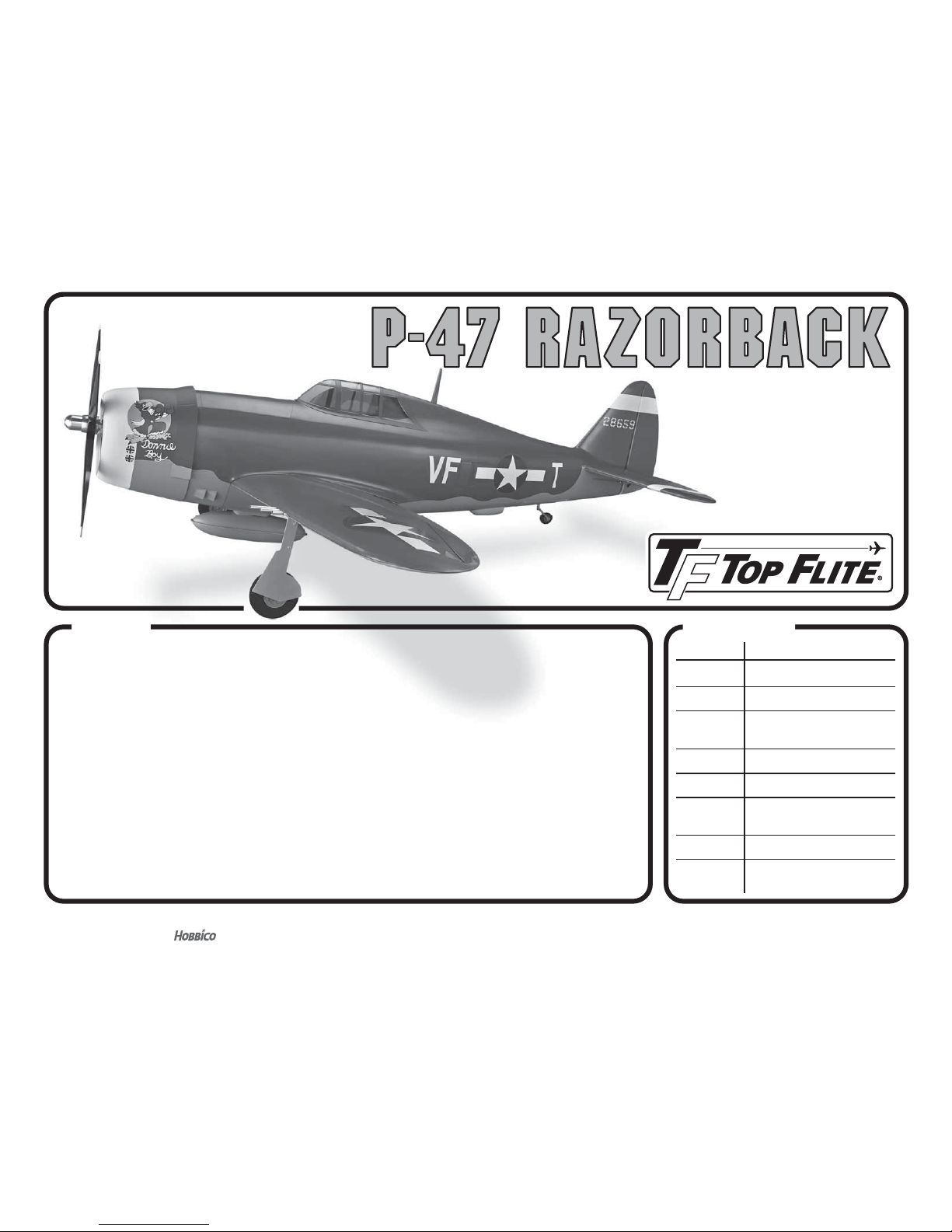
INTRODUCTION
The P-47 Razorback has been recognized as an
excellent modeling subject. The large wing and tail
area and lo ng tail m oment ma ke an ide al fl ying airplane
– especially for a warbird! The Top Flite Giant P-47 (with
Razorback option) kit is a very successful model. Now,
Top Flite has developed the Giant P-47 Razorback
ARF following the same design as the kit. The Giant
P-47 Razorback ARF will get you in the air quickly
with a great looking model, without the sanding and
covering required to build a kit.
For the latest technical updates or manual corrections
to the Giant P-47 Razorback ARF visit the Top Flite
web site at www.top-fl ite.com. Open the “Airplanes”
link, then select the Giant P-47 Razorback ARF. If
there is new technical information or changes to this
model a “tech notice” box will appear in the upper left
corner of the page.
AMA
If you are not already a member of the AMA, please
join! The AMA is the governing body of model aviation
and membership provides liability insurance coverage,
protects modelers’ rights and interests and is required
to fl y at most R/C sites.
Academy of Model Aeronautics
5151 East M em orial Dr ive
Muncie, IN 47302-9252
Ph. (800) 435-9262 Or via the Internet at:
Fax (765) 741-0057 www.modelaircraft.org
IMPORTANT!!! Two of the most important things you
can do to preserve the radio controlled aircraft hobby
are to avoid fl ying near full-scale aircraft and avoid
fl ying near or over groups of people.
SCALE COMPETITION
Though the Top Flite Giant P-47 Razorback is an ARF
and may not have the same level of detail as an “all-out”
scratch-built competition model, it is a scale model
nonetheless and is therefore eligible to compete in
TABLE OF CONTENTS
Page 3

3
the Fun Scale class in AMA competition (we receive
many favorable reports of Top Flite ARFs in scale
competition!). In Fun Scale, the “builder of the model”
rule does not apply. To receive the fi ve points for scale
documentation, the only proof required that a full size
aircraft of this type in this paint/markings scheme did
exist is a single sheet such as a kit box cover from a
plastic model, a photo, or a profi le painting, etc. If the
photo is in black and white, other written documentation
of color must be provided. Contact the AMA for a rule
book with full details.
SAFETY PRECAUTIONS
Protect Your Model, Yourself & Others…
Follow These Important Safety Precautions
1. Your Giant P-47 Razorback ARF should not be
considered a toy, but rather a sophisticated, working
model that functions very much like a full-size airplane.
Because of its performance capabilities, the Giant
P-47 Razorback ARF, if not assembled and operated
correctly, could possibly cause injury to yourself or
spectators and damage to property.
2. You must assemble the model according to the
instructions. Do not alter or modify the model, as
doing so may result in an unsafe or unfl yable model.
In a few cases the instructions may differ slightly from
the photos. In those instances the written instructions
should be considered as correct.
3. You must take time to build straight, true and
strong.
4. You must use an R/C radio system that is in
good condition, a correctly sized engine, and other
components as specifi ed in this instruction manual.
All components must be correctly installed so that the
model operates correctly on the ground and in the air.
You must check the operation of the model and all
components before every fl i g h t .
5. If you are not an experienced pilot or have not
fl own this type of model before, we recommend that
you get the assistance of an experienced pilot in your
R/C club for your fi rst fl ights. If you’re not a member
of a club, your local hobby shop has information
ab out cl ubs in yo ur area w hose m ember ship i ncl ud es
experienced pilots.
6. While this kit has been fl ight tested to exceed normal
use, if the plane will be used for extremely high stress
fl ying, such as racing, or if an engine larger than one
in the recommended range is used, the modeler is
responsible for taking steps to reinforce the high stress
points an d /or su bs ti tuting hardware more sui ta ble for
the increased stress.
7. WARNING: The cowl and landing gear covers
included in this kit are made of fi berglass, the fi bers
of which may cause eye, skin and respiratory tract
irritation. Never blow into a part to remove fi berglass
du st , as the d ust will blow bac k into your eyes. A lway s
wear safety goggles, a particle mask and rubber gloves
when grinding, drilling and sanding fi berglass parts.
Vacuum the parts and the work area thoroughly after
working with fi berglass parts.
We, as the kit manufacturer, provide you with a top
quality, thoroughly tested kit and instructions, but
ultimately the quality and fl yability of your fi nished
model depends on how you build it; therefore, we
cannot in any way guarantee the performance of
your completed model, and no representations
are expressed or implied as to the performance or
safety of your completed model.
REMEMBER: Take your t ime a nd f oll ow th e in stru ctio ns
to end up with a well-built model that is straight and true.
DECISIONS YOU MUST MAKE
This is a partial list of items required to fi nish
the Giant P-47 Razorback ARF that may require
planning or decision making before starting to
build. Order numbers are provided in parentheses.
ENGINE RECOMMENDATIONS
When considering engines for this model, refer to
the engine size recommendations on the cover of
the manual. Spark-ignition “gas” engines are most
popular with large-scale warbirds such as this. One
advantage of a gas engine is economy – gas engines
tend to con sume l ess fu el tha n a glow e ngine as wel l.
Additionally, gas engines deposit little exhaust residue
on the model. Among other engines, this model was
test fl own with a DLE 61 engine. The DLE 61 provides
more than adequate power and fl ies the Giant P-47
Razorback ARF in a scale-like manner.
NOTE: Instructions for mounting every possible engine
cannot be incorporated into this manual. Modelers
using another engine may refer to the instructions
as a guide for mounting their engine in a similar way.
ELECTRIC MOTOR RECOMMENDATIONS
❍
Great Planes RimFire 65cc (80-85-160)
Outrunner Brushless Motor (GPMG4805)
❍
Castle Creations Phoenix Edge 160HV 50V
160 amp ESC (CSEM0300)
❍
Two FlightPower LiPo FP50 5000mAh 22.2V
batteries (FPWP5506)
❍
Great Planes Standoff Brushless Motor
Mount XX Large (GPMG1275)
RADIO EQUIPMENT
The radio equipment and number of channels required
to fl y the Top Flite Giant P-47 Razorback ARF depends
on the capabilities of your transmitter and how the
servos will be connected.
Page 4
4
The Giant P-47 Razorback ARF requires a servo to
operate the air control valve if using pneumatic retracts,
a throttle servo, two fl ap servos, two aileron servos,
two elevator servos and a rudder servo. Servos with a
minimum of 50 oz-in [3.9kg-cm] of torque are required
for operating the elevators, rudder, ailerons and fl aps.
We reco mmend that met al geare d servos als o be us ed.
Standard servos may be used for the throttle and choke
(the servo operated choke is optional). A micro servo
is required to operate the retract air valve. An optional
servo o perate d kill switch may also b e u se d (this is in
addition to the manually operated engine kill switch.
A servo operated kill switch is only really necessary
for engines that do not reliably shut off by closing the
carburetor, but could also serve as a backup.
Function Type RequiredQty.
Elevators 2
Futaba
S3305
(FUTM0045)
min. 50 oz-in torque
Rudder 1
Futaba
S3305
(FUTM0045)
min. 50 oz-in torque
Ailerons 2
Futaba
S3305
(FUTM0045)
min. 50 oz-in torque
Flaps 2
Futaba
S3305
(FUTM0045)
min. 50 oz-in torque
Tail Wheel
Steering
1
Futaba
S3305
(FUTM0045)
min. 50 oz-in torque
Throttle 1
Futaba
S3004
(FUTM0027)
standard
Retract 1
Futaba
S3102
(FUTM0034)
micro
Optional
Choke
Futaba
S3004
(FUTM0027)
standard
1
Total10 –11
A receiver battery with a minimum of 1,000mAh is
recommended for fl ying the Giant P-47 Razorback
ARF. The battery voltage should be checked before
every fl ight to be certain it has enough “charge”.
In addition to the servos, the following items (or similar
items) are also required. The order numbers shown
in parentheses are for Futaba servos.
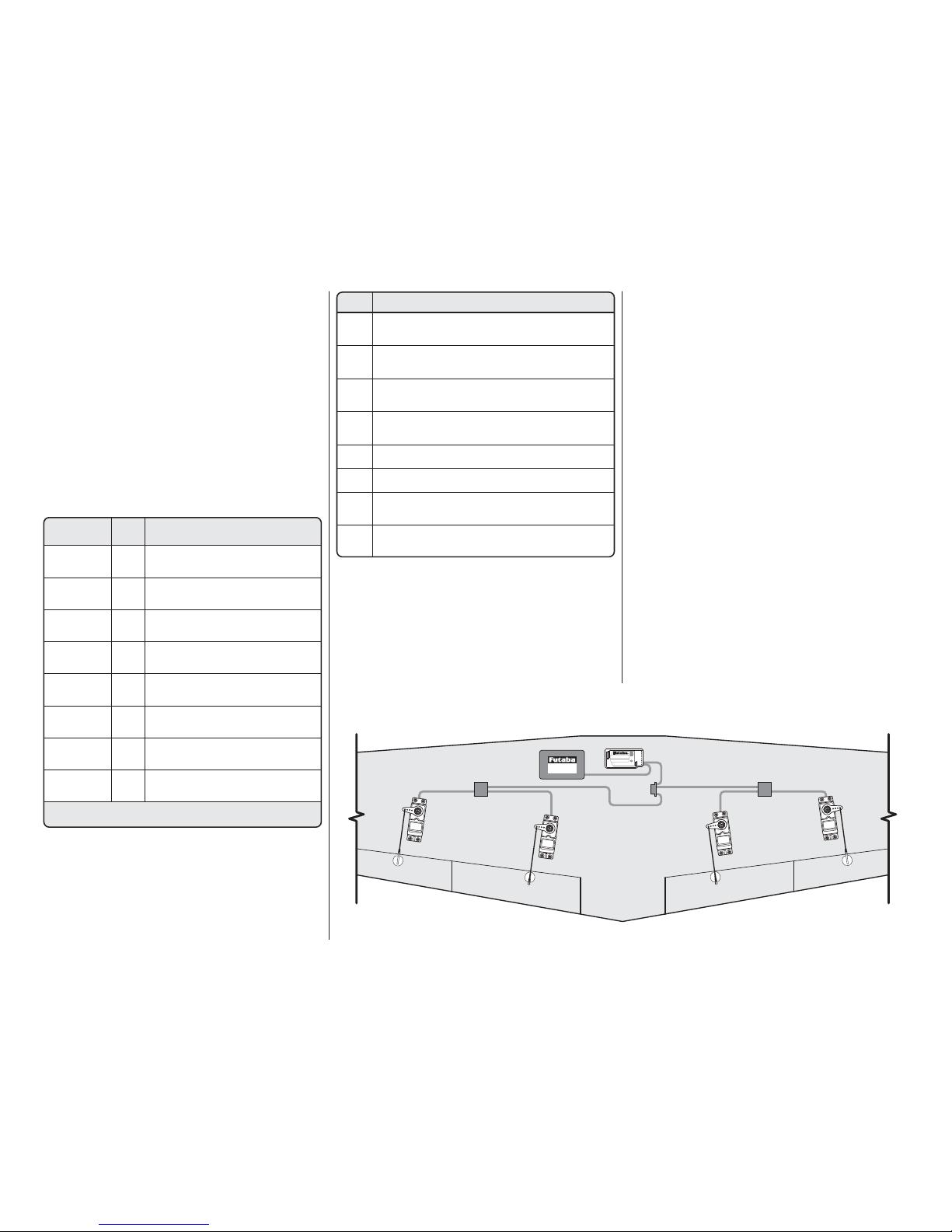
Battery
S.Bus Receiver
Hub
Hub
Hub
Servo Servo ServoServo
WING
S.BUS SYSTEM
Items RequiredQty.
4
6" Y-harness
for elevator, rudder/steering,
ailerons & flaps (FUTM4130)
4
6" Servo Extension
for throttle, optional
choke, ailerons & flaps (HCAM2701)
3
12" [305mm] Servo Extension
for flaps & receiver switch (HCAM2711)
2
24" [610mm] Servo Extension
for ailerons (HCAM2721)
2
Heavy Duty Switch Harness
(FUTM4385)
2
Ernst Charge Receptacle 124
(ERNM3001)
1
Hobbico LiFeSource Battery
6.6V 3200mAh (Receiver) (HCAM6446)
1
Hobbico LiFeSource Battery
6.6V 1100mAh (Ignition) (HCAM6416)
Note: The length and quantity of servo extensions
and Y-connectors may vary depending on the brand
of radio you are using and the radio installation.
The instructions show the two aileron servos
connected with a Y-harness that is plugged into the
aileron channel of the receiver. If using a computer
radio, the two aileron servos can be plugged into
separate channels of the receiver and mixed together.
The two fl ap servos and the two elevator servos also
use a Y-harness. If plugging the servos into separate
channels, follow the instructions included with your
radio system on how to mix the channels.
S.BUS SYSTEM
A cutting edge alternative to standard
servo installation!
The innovative Futaba S.Bus system lets you unleash
your fl ight system’s full potential and cut down on
cable clutter at the same time. It uses digital serial
data communication technology to transmit control
signals between your receiver and servos. A single
S.Bus cable can carry signals to as many channels
as your transmitter can handle. You no longer have to
worry about plugging in the wrong servo to the wrong
channel, because each servo knows what channel it
is dedicated to in advance.
SBD-1 S.Bus Decoder Cables allow the use of existing
analog and digital servos, too. By providing today’s
pilots with tomorrow’s technology, the Futaba S.Bus
system is nothing short of revolutionary.
Page 5
5
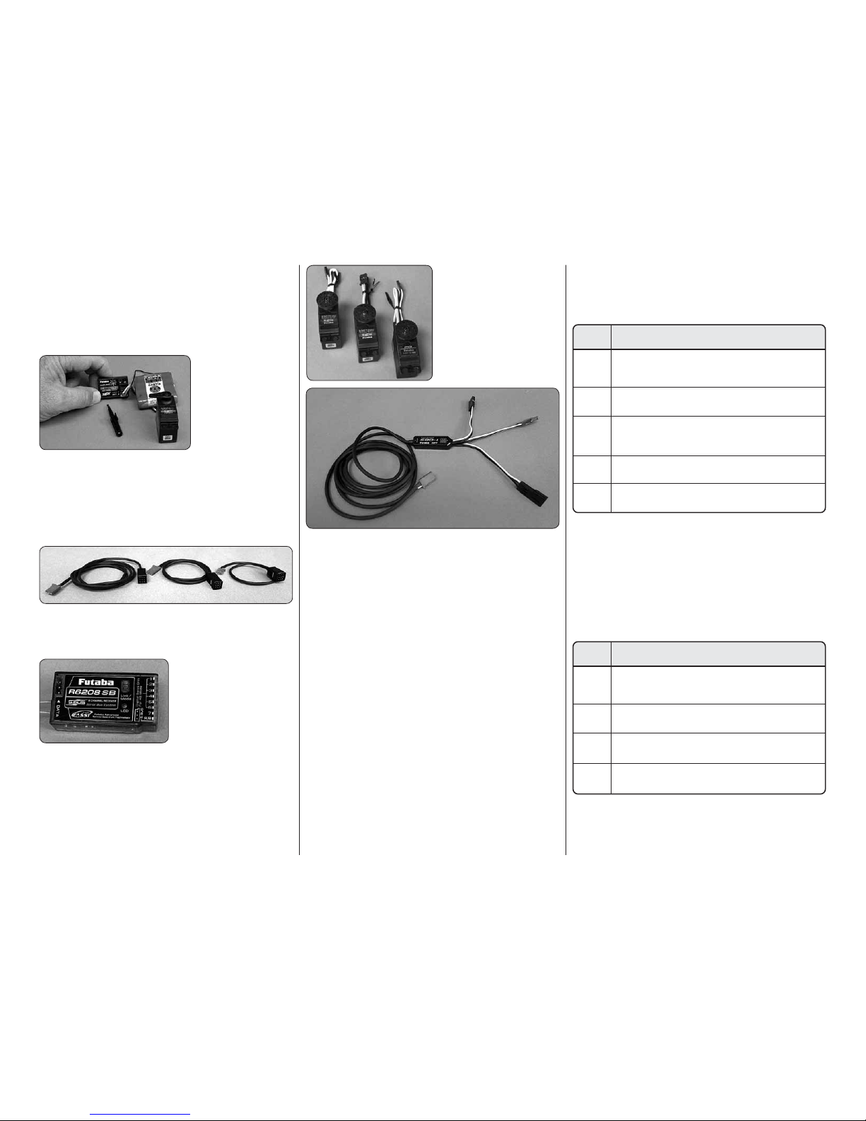
HOW DO YOU INSTALL THE S.BUS SYSTEM?
Installation is actually simplifi ed as compared to your
normal system installation. Using the S.Bus system
you plug a battery into the SBC-1 channel changing
tool, using it to program which channel you want the
servo to operate on.
Once programmed
the servo will
operate as required
regardless of which
lead it is plugged
into. Do this for all of
the servos that you
want to operate on
the S.Bus system. Install the servos in the airplane and
plug them into the S.Bus lead, piggybacking them one
onto another. Once completed you plug one lead into
the receiver for all of the servos and all of the servos
will function as programmed. One lead operates up
to 16 servos!
S.Bus leads are available in a number of different
lengths to accommodate installation into any size
airplane regardless of its complexity.
There are many choices
for the S. Bus receivers;
some are tiny 3 port
receivers with others
being up to 8 channels.
The 8 channel inputs can
be used as you would
normally set up a model, allowing you to split the model
and have some of it set up as S.Bus while other servos
are not using the S. Bus system. Something else to
note is that some of the S. Bus servos and receivers
are HV or High Voltage, meaning that you could run
a straight 2S LiPo for your receiver battery.
Many servo choices are
available for use in a
wide variety and sizes
of aircraft from micros to
the largest models.
Your system is not limited to programming only through
the SBC-1 channel changing tool and your transmitter.
Utilizing the USB interface, the CIU-2, you can do all of
the programming using your PC. Programming with this
interface gives more fl exibility and programming options
than can be achieved with any other radio system. To
utilize standard non S.Bus servos you simply use the
S.Bus decoder instead of the S.Bus lead.
This is just the beginning of what this system can do.
Would you like to operate the servos in the wing with
a separate battery from the fuselage? With S.Bus you
can do that! Run multiple servos – using only a single
channel on your transmitter!!
WANT MORE INFORMATION?
Visit www.futaba-rc.com for more information,
diagrams and helpful videos showing the complete
operation of the S.Bus system.
RETRACTABLE LANDING GEAR
The Top Flite Giant P-47 Razorback ARF may be
assembled with either the Robart pneumatic or electric
retracts. Following is the complete list of items required
to install the Robart retracts:
PNEUMATIC RETRACTS
Items RequiredQty.
1
Robart #622P47
Top Flite Giant P-47
Pneumatic Retractable Main Landing Gear
(ROBQ1636)
1
Robart #160LWC
Retractable Tail Gear
Assembly (ROBQ2225)
1
Robart #157VRX
Large-Scale Deluxe Air
Control Kit – incl. pressure tank, air line tubing,
variable-rate air valve, T-fittings (ROBQ2305)
1
Robart #169
10' [3048mm] Red & Purple
Pressure Tubing (ROBQ2369)
1 pkg.
Robart #190
Air Line Quick Disconnects (ROBQ2395)
Note: An air pump will als o be re quired to pressurize
the air tank. The Robart hand pump could be used,
but is not practical because of the large capacity of
the air tank in this model. A small, 12V electric pump is
recommended and can be purchased at an automotive
or hardware store.
ELECTRIC RETRACTS
Items RequiredQty.
1
Robart #622P47E
Top Flite Giant P-47
Electric Retractable Main Landing Gear
(ROBQ1637)
1
Robart #160LWCE
Electric Retractable
Tail Gear Assembly (ROBQ2226)
1
Robart #177E24S
24" Actuator Extension
(ROBM0180)
1
Robart #177E12
12" Actuator Extension
(ROBM0177)
Page 6

6
ADDITIONAL ITEMS REQUIRED
REQUIRED HARDWARE AND ACCESSORIES
In addition to the items listed in the “Decisions You
Must Make” section, following is the list of hardware
and accessories required to fi nish the Top Flite Giant
P-47 Razorback ARF. Order numbers are provided
in parentheses.
❍ (2) Dubro #813 1/8" Fuel Line Barb (DUBQ0670)
❍ (1) Dubro #554 X-large Tygon Fuel Line
(DUBQ0427)
❍ (1) R/C foam rubber (1/4" [6mm] (HCAQ1000) or
1/2" [13mm] (HCAQ1050)
❍ Optional Black paint for the plywood radial
engine frame
❍ Propeller and spare propellers suitable for your
engine or motor.
❍ Painted Pilot (GPMA2807) or Best Pilots at
http://www.bestpilots.typepad.com
❍ Spinner Adapter (elec. only) (GPMQ4590)
❍ 10 - 32 x1" Socket Head Cap Screw (Elec. only)
ADHESIVES AND BUILDING SUPPLIES
This is the list of Adhesives and Building Supplies that
are required to fi nish the Giant P-47 Razorback ARF.
❍ 1/2 oz. [15g] Thin Pro™ CA (GPMR6001)
❍ 1/2 oz. [15g] Medium Pro CA+ (GPMR6007)
❍ Pro 30-minute epoxy (GPMR6047)
❍ Pro 6-minute epoxy (GPMR6045)
❍ Threadlocker thread locking cement
(GPMR6060)
❍ Mixing sticks (50, GPMR8055)
❍ Mixing cups (GPMR8056)
❍ Epoxy brushes (6, GPMR8060)
❍ Denatured alcohol (for epoxy clean up)
❍ PT-56 canopy glue (PAAR3300)
❍ Milled fi berglass (GPMR6165)
❍ Masking tape
❍ Drill bits: 1/16" [1.6 mm], 5/64" [2 mm],
3/32" [2.4 mm], 7/64" [2.8 mm], 1/8" [3.2 mm],
3/16" [4.8 mm], 13/64" [5 mm], 1/4" [6.4 mm] ,
5/16" [8 mm]
❍ Small metal fi le
❍ Stick-on segmented lead weights (GPMQ4485)
❍ Silver solder w/fl ux (STAR2000)
❍ Revell #1 Lt Duty Alum Handle Knife w/ Blade &
Safety Cap (RMXR6903)
❍ Revell #11 Light Duty Blades (5-pack,
RMXR6930)
❍ Curved-tip canopy scissors for trimming plastic
parts (HCAR0667)
❍ Hobbico Soldering Iron 60 Watt (HCAR0776)
Covering tools
❍ Top Flite MonoKote® sealing iron (TOPR2100)
❍ Top Flite Hot Sock™ iron cover (TOPR2175)
❍ Top Flite MonoKote trim seal iron (TOPR2200)
❍ Top Flite MonoKote heat gun (TOPR2000)
OPTIONAL SUPPLIES AND TOOLS
Here is a list of optional tools mentioned in the manual
that will help you build the Giant P-47 Razorback ARF.
❍ 2 oz. [57g] spray CA activator (GPMR6035)
❍ CA applicator tips (HCAR3780)
❍ CA debonder (GPMR6039)
❍ Builder’s Triangle Set (HCAR0480)
❍ 36" metal ruler
❍ Hobbico® High Precision Diagonal Cutter 5"
(HCAR0630)
❍ Pliers with wire cutter (HCAR0625)
❍ Robart Super Stand II (ROBP1402)
❍ Panel Line Pen (TOPQ2510)
❍ Rotary tool such as Dremel
❍ Rotary tool reinforced cut-off wheel (GPMR8200)
❍ Servo horn drill (HCAR0698)
❍ AccuThrow™ Defl ection Gauge (GPMR2405)
❍ CG Machine™ (GPMR2400)
❍ Precision Magnetic Prop Balancer (TOPQ5700)
IMPORTANT BUILDING NOTES
● Anytime a sheet metal screw is installed in wood,
fi rst install the screw, remove the screw and apply a
couple of drops of thin CA in the hole to harden the
threads. After the CA has cured, reinstall the screw.
● Photos and sketches are placed before the step
they refer to. Frequently you can study photos in
following steps to get another view of the same parts.
● The Giant P-47 Razorback ARF is factory-covered
with Top Flite Flat MonoKote fi lm. Should repairs
ever be required, MonoKote can be patched with
additional MonoKote purchased separately. MonoKote
is pa ckage d in si x-fo ot ro lls, b ut som e hobb y shop s also
sell it by the foot. If only a small piece of MonoKote is
needed for a minor patch, perhaps a fellow modeler
would give you some. MonoKote is applied with a
model airplane covering iron, but in an emergency a
regular iron could be used. A roll of MonoKote includes
full instructions for application. Following are the colors
used on this model and order numbers for six foot rolls.
Flat Olive Drab (TOPQ0510)
Flat Dove Gray (TOPQ0511)
● The stabilizer and wing incidences and engine
thrust angles have been factory-built into this model.
However, s ome tech nic ally-mi nded m ode le rs may wi sh
to check these measurements anyway. To view this
information visit the web site at www.greatplanes.com
and click on “Technical Data.” Due to manufacturing
tolerances which will have little or no effect on the
way your model will fl y, please expect slight deviations
between your model and the published values.
KIT INSPECTION
Before starting to build, take an inventory of this kit
to make sure it is complete, and inspect the parts to
make sure th ey are of acceptable q ua lity. If any parts
are missing or are not of acceptable quality, or if you
need assistance with assembly, contact Product
Support. When reporting defective or missing parts,
use the part names exactly as they are written in the
Kit Contents list.
Top Flite Product Support
3002 N Apollo Drive, Suite 1
Champaign, IL 61822
Ph: (217) 398-8970, ext. 5
Fax: (217) 398-7721
E-mail: airsupport@top-fl ite.com
Page 7
7
ORDERING REPLACEMENT PARTS
Replacement parts for the Top Flite Giant P-47
Razorback ARF are available using the order numbers
in the Replacement Parts List that follows. The
fastest, most economical service can be provided
by your hobby dealer or mail-order company. Not all
parts are available separately (an aileron cannot be
purchased separately, but is only available with the
wing kit). Replacement parts are not available from
Product Support, but can be purchased from hobby
shops or mail order/Internet order fi rms. Hardware
items (screws, nuts, bolts) are also available from
these outlets.
To locate a hobby dealer, visit www.top-fl ite.com
and click on “Where to Buy”. Follow the instructions
provided on the page to locate a U.S., Canadian or
International dealer.
Parts may also be ordered directly from Hobby
Services by calling (217) 398-0007, or via facsimile
at (217) 398-7721, but full retail prices and shipping
and handling charges will apply. Illinois and Nevada
residents will also be charged sales tax. If ordering
via fax, include a Visa or MasterCard number and
expiration date for payment.
Mail parts orders Hobby Services
and payments by 3002 N Apollo Drive, Suite 1
personal check to: Champaign IL 61822
Be certain to specify the order number exactly as listed
in the Replacement Parts List. Payment by credit
card or personal check only; no C.O.D.
If additional assistance is required for any reason
contact Product Support by e-mail at productsupport@
top-fl ite.com, or by telephone at (217) 398-8970.
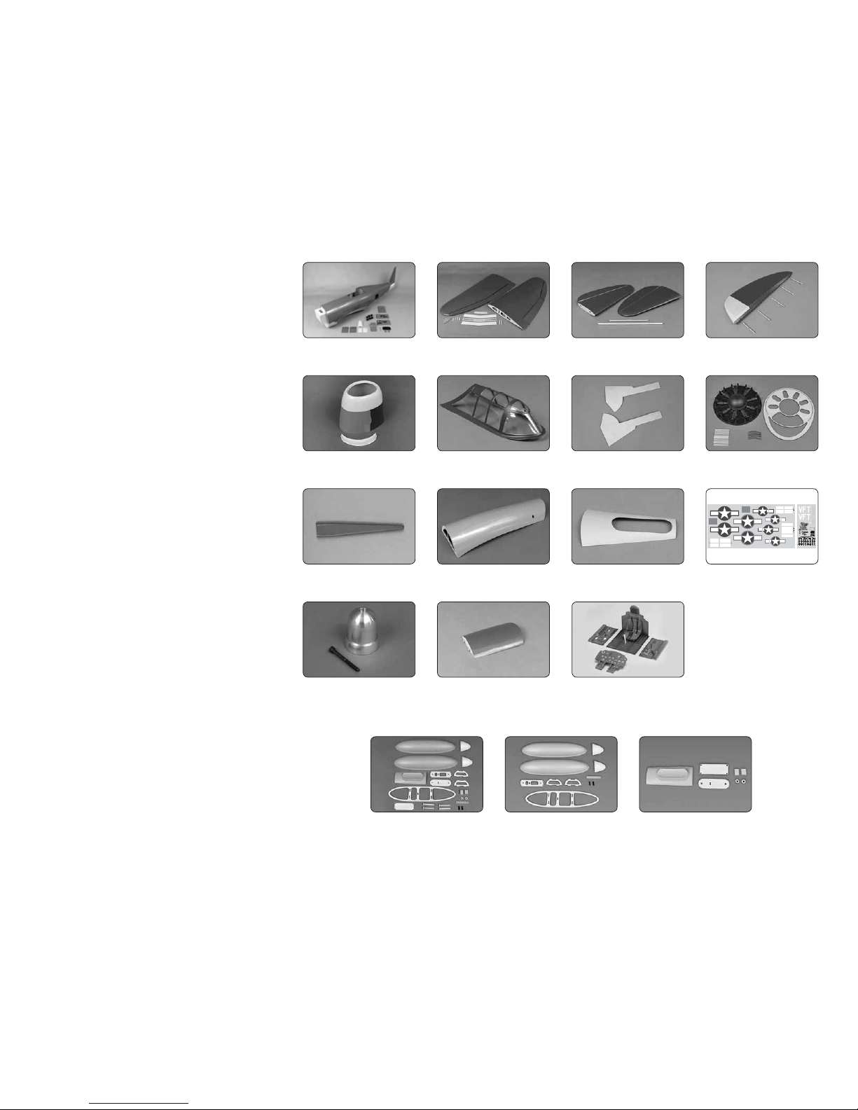
TOPQ8410
COCKPIT KIT
TOPA1975
SPINNER
TOPA1976
HATCH
TOPA1960
FUSELAGE
TOPA1961
WING
TOPA1962
HORIZONTAL STABILIZERS
TOPA1963
RUDDER
TOPA1964
COWL
TOPA1965
CANOPY
TOPA1966
GEAR DOORS
TOPA1967
DUMMY ENGINE
TOPA1971
ANTENNA
TOPA1972
BELLY PAN
TOPA1973
TAI L HATC H
TOPA1974
DECALS
TOPA1968
DROP TANK COMPLETE
OPTIONAL
TOPA1969
DROP TANK ONLY
TOPA1970
DROP TANK RELEASE
Page 8
8
ASSEMBLE THE WINGS
HINGE THE AILERONS
Start with the left wing so the assembly matches the
photos the fi rst time through.
❏ 1. Pull on the ailerons and elevators, making sure
the hinges are secure.
❏ ❏ 2. If necessary, use a covering iron with a
covering sock to go over the wing, fl ap and aileron
to remove any wrinkles. The best method to remove
the wrinkles is to glide the iron over the covering until
the wrinkles disappear, then go over the area again,
pushing down on the iron to bond the covering to the
wood. If the wrinkles don’t disappear, the balsa in
that area might be fl exing inward. If this is happening,
don’t press down. Simply let the heat of the iron shrink
the covering. If the wrinkles momentarily disappear,
then immediately reappear, the iron may be too hot,
thus causing air bubbles. Lower the temperature of
the iron or use a sharp #11 blade to puncture several
holes in the covering, then reheat. The suggested iron
temperature is around 360 degrees F.
The P-47 had many attributes that led to its
reputation. One of the most important was its
durability in combat. Oftentimes the P-47 would
bring pilots home with missing cylinders, blown-off
wing tips and large portions of tail surfaces missing.
The P-47’s internal systems were very durable and
well protected.
MOUNT THE AILERON SERVOS
❏ ❏ 1. Install a servo arm on the aileron servo.
Connect the servo to your receiver. Switch on the
transmitter and center the servo arm. Position the
aileron servo on the aileron servo hatch cover as shown
with the servo arm centered in the opening. Set the two
5/16" x 5/8" x 13/16" [7.9 x 15.8 x 20.6mm] hardwood
blocks in the embossed servo block locations, checking
that they are correct. If not, mark the new location.
❏ ❏ 2. Use 6-minute epoxy to glue the two blocks
to the bottom of the servo hatch over the embossed
servo block locations. Thoroughly coat the end of the
blocks and allow them to set for a few seconds while
the blocks absorb the epoxy. Then, recoat the blocks.
Use clamps to hold the blocks to the servo hatch tray.
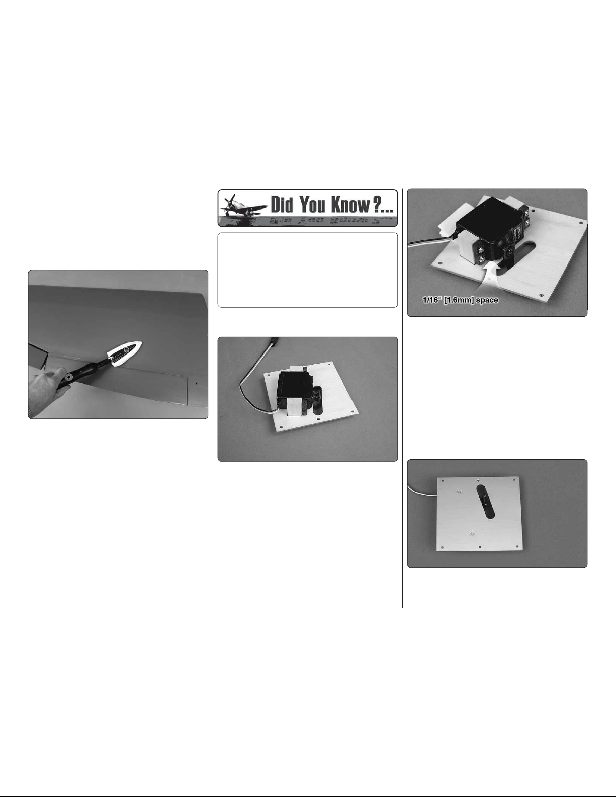
❏ ❏
3. Once the epoxy has cured, remove the clamps.
Place a 1/16" [1.6mm] spacer, such as a piece of
cardstock or a piece of paper folded several times,
under the servo and between each mounting block.
After the servo is installed the spacer will be removed,
providing adequate spacing for vibration isolation.
❏ ❏ 4. Drill 1/16" [1.6mm] holes through the blocks
for the servo mounting screws. Mount the servo to
the blocks with the screws that came with the servo.
Remove the servo mounting screws and apply a couple
of dr ops of th in CA in each hol e to h arden th e thread s.
Allow the CA to fully harden. Then, reinstall the servos
and remove the spacer.
❏ ❏ 5. Drill 1/16" [1.6mm] holes through the blocks at
the two hole locations on the top of the aileron servo
hatch. Install two #2 x 3 /8" [9.5mm] fl at head sheet
Page 9
9
metal screws to secure the servo mounting blocks to
the aileron servo hatch. Use thin CA to harden the
screw threads.
❏ ❏ 6. Connect a 24" [610mm] servo extension wire
to the aileron servo. Cut a piece of heat shrink tubing
in half and slide it over the servo connections. Shrink
the tubing by applying heat to the tubing.
❏ ❏ 7. Use the string in the wing to pull the aileron
servo wire through the wing.
❏ ❏ 8. Place the aileron servo hatch with the servo
in the wing. Be certain that the hatch is positioned
correctly as shown. Secure the hatches using six # 2
x 3/8" [9.5mm] fl at head sheet metal screws. Use thin
CA to harden the screw threads.
❏ 9. Go back to step 1 and install the right aileron
servo following the same procedure.
MOUNT THE RETRACTS
Install the left retract fi rst.
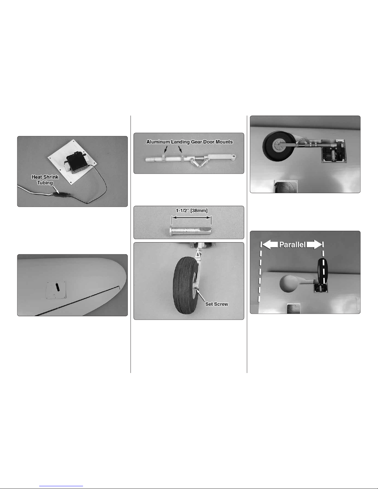
❏ ❏
1. Use a hex wrench to loosen the strut mounting
bolt and remove the strut. Slide two aluminum landing
gear door mounts onto the strut and reinstall the strut
in the strut mount.
❏ ❏ 2. Trim the axle that is included with the Robart
retracts to 1-1/2" [38mm] long. File a fl at spot at the
end of the axle. Insert the axle through the included
5" [127mm] wheel and into the retract. Apply a drop of
threadlocker to the 10-32 x 3/16" [4.8mm] set screw,
included with the retract, and tighten the set screw
onto the fl at of the axle. Make sure that the wheel
rotates freely.
❏ ❏ 3. Test fi t the retract unit with the wheel into the
wing. Position the retract so the wheel is centered in
the wheel well. Adjust the strut position in the retract
body as necessary to achieve the correct spacing all
the way around the wheel.
❏ ❏
4. Extend the retract. View the wheel from directly
above. Adjust the strut so that the wheel is parallel
to the root of the wing. Lock the strut in position by
applying a drop of threadlocker to the threads and
securely tightening the bolts at the top of the strut.
❏ ❏ 5. Double check that the wheel will fully retract
into the wing. Extend the retract to make sure it does
not interfere with any part of the wing and that the
retract is operating smoothly.
Page 10
10
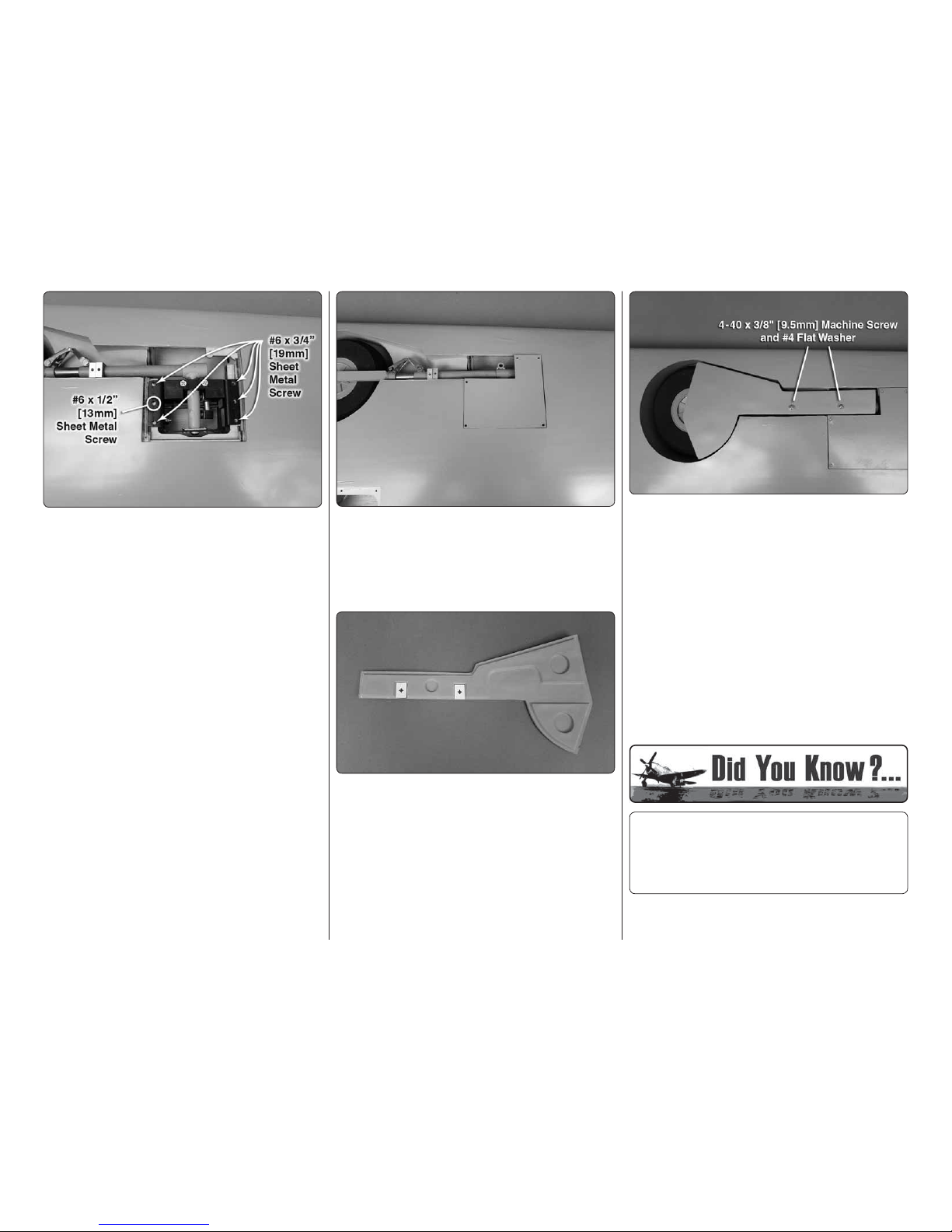
❏ ❏ 6. Hold the retract in the wing. Using the mounting
holes as a guide, drill 7/64" [2.8mm] pilot holes into
the retract rails. Caution: Do not inadvertently drill
into the electric actuator when you get to the middle
hole. Mount the retracts with fi ve #6 x 3/4" [19.1mm]
sheet metal screws, one in each corner and one in the
middle as shown. Use one #6 x 1/2" [12.7mm] sheet
metal screw in the hole over the electric actuator.
❏
7. Remove the six screws and retract and apply a
couple of drops of thin CA in the holes. Attach a 12"
Actuator Extension to the retract. If installing pneumatic
retracts, attach the airline to the retracts.
❏
8. Connect the actuator extension or air lines to the
string in the retract bay. Guide the extension or air lines
through the front of the retract bay, through the fl ap
bay and out the hole in the top of the wing. Also pull
the aileron servo lead out the hole. Tape the actuator
extension or air lines and aileron servo extension to
the top of the wing. Remount the retract in the wing.
❏ ❏ 9. Set the retract cover over the retract and drill
a 1/16" [1.6mm] pilot hole using the holes in the cover
as a guide.
❏ ❏ 10. Mount the retract cover to the wing with fi ve
#2 x 3/8" [9.5mm] fl at head sheet metal screws.
❏ ❏ 11. Cut two of the landing gear door drill guides
from the back of the manual. Place the drill guides
in the rectangle recesses of the landing gear door.
Place the landing gear door on a piece of scrap wood
and drill a 1/8" [3.2mm] hole through the door at the
marked hole location.
❏ ❏ 12. Adjust the position of the two landing gear
door mounts so that they align with the fl ats on the
landing gear door when the door is positioned in the
landing gear opening.
❏ ❏
13. Install a #4 fl at wash er on 4 -40 x 3/8" [9. 5m m]
machine screw. Insert the machine screw through
one of the holes in the gear door and thread it into the
land ing gear door m ount. Note that i t tigh te ns ag ainst
the landing gear strut before it tightens against the
gear door. Install the second machine screw to hold
th e g ear do or in pos ition. C hec k t o make sure that the
gear door is fl ush with the bottom of the wing. 1.5mm
thick rectangular plywood spacers have been included
to space the gear doors out if needed. Both screws
will need to b e s hor tened, a li ttl e a t a time, so th at they
tighten against both the landing gear strut and the
gear door. Be sure to use threadlocker on the screws.
❏ 14. Return to step 1 and mount the retract in the
right wing.
The P-47 was manufactured by Republic Aircraft
Corporation, which at one time was named
Seversky Aircraft Corporation, started by two fellow
Russians, Alexander De Seversky and Alexander
Kartveli.
Page 11

11
INSTALL THE FLAP SERVOS
❏ ❏
1. Install the fl ap servos following the same
procedure used to install the aileron servos. Note that
the fl ap servos face the same direction.
❏ ❏
2. Connect a 12" [305mm] servo extension wire
to the fl ap servo. Secure the extension to the servo
with a piece of heat shrink or electrical tape.
❏ ❏ 3. Route the fl ap servo leads to the root of the
wing and out the hole in the top of the wing.
INSTALL THE AILERON AND
FLAP PUSHRODS
Do the left aileron fi rst. Temporarily plug the aileron
servo into the receiver. Switch on your transmitter
and plug a receiver battery into the receiver. Center
the aileron trim.
❏ ❏
1. Slide a silicone clevis retainer over a 4-40
threaded metal clevis. Thread a 4-40 nut followed by
the 4-40 metal clevis, threaded 12 turns onto a 4-40
x 12" [305mm] metal pushrod. Attach the clevis to
the aileron servo arm 5/8" [15.9mm] from the center
of the arm.
❏ ❏
2. Posi tion t he contr ol hor n s o that it is inl in e with
the pushrod and over the plywood mounting plate. The
pushrod holes in the control horn should be aligned
with the hinge line of the aileron. On the aileron, mark
the four mounting holes. Remove the control horn and
drill a 5/64" [2mm] pilot hole at each mark. Do not drill
completely through the aileron. Attach the control horn
using four #4 x 1/2" [12.7mm] sheet metal screws. Use
thin CA to harden the holes.
❏ ❏ 3. Install the metal solder clevis in the second
hole from the end of the control horn. Center the
aileron servo and aileron. Mark the pushrod where it
meets the solder clevis. Remove the pushrod and the
solder clevis and cut the pushrod 1/4" [6.4mm] past
the mark. Solder the solder clevis to the pushrod using
the techniques described in the following Hot Tip.
HOW TO SOLDER
1. Use denatured alcohol or other solvent to
thoroughly clean the pushrod. Roughen the end of
the pushrod with coarse sandpaper where it is to
be soldered.
2. Apply a few drops of soldering fl ux to the end of
the pushrod, then use a soldering iron or a torch
to heat it. “Tin” the heated area with silver solder
by applying the solder to the end. The heat of the
pushrod should melt the solder – not the fl ame
of the torch or soldering iron – thus allowing the
solder to fl ow. The end of the wire should be coated
with solder all the way around.
3. Place the clevis on the end of the pushrod. Add
another drop of fl ux, then heat and add solder.
The same as before, the heat of the parts being
soldered should melt the solder, thus allowing
it to fl ow. Allow the joint to cool naturally without
disturbing. Avoid excess blobs, but make certain
the joint is thoroughly soldered. The solder should
be shiny, not rough. If necessary, reheat the joint
and allow to cool.
4. Immediately after the solder has solidifi ed, but
while it is still hot, use a cloth to quickly wipe off
the fl ux before it hardens. Important: After the joint
cools, coat the joint with oil to prevent rust. Note:
Do not use the acid fl ux that comes with silver
solder for electrical soldering.
This is what a properly soldered clevis looks
like – shiny solder with good flow, no blobs and
flux removed.
Page 12
12
❏ ❏
4. Slide a silicone clevis retainer over the solder
clevis. Reinstall the aileron pushrod with the threaded
clevis attached to the control horn.
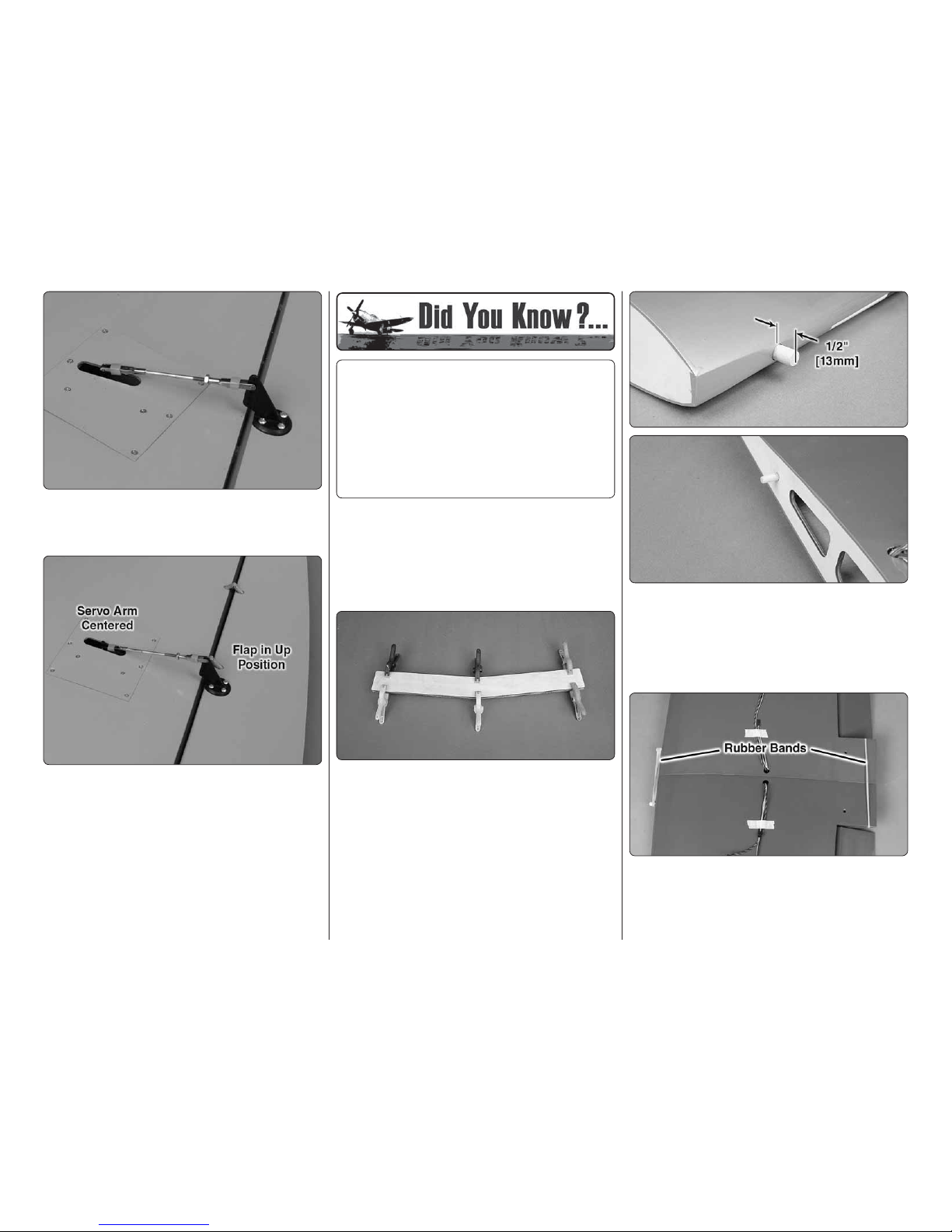
❏ ❏
5. Assemble and connect the fl ap pushrods
following the same procedure. We installed the pushrod
in the outer hole of the control horn and the hole 3 /8"
[9.5mm] from the center of the servo arm. Note: With
the fl ap fully retracted “up”, the servo arm is centered
on the servo.
❏ 6. Return to step 1 and install the aileron and fl ap
pushrods on the right wing.
The Thunderbolt was a massive airplane, the
biggest and heaviest single engine, single-place
fi ghter ever built. The engine, the Pratt & Whitney
18 cylinder twin-row radial, developed 2,000 HP
and was the most powerful engine at the time.
However, in turn, it needed a highly effi cient
duct system for its super-charger. The designer,
Alexander Kartvile, designed the duct system fi rst,
then built the fuselage around it.
JOIN THE WING
Note: Keep the retracts in the retracted (up) position so
they do not extend and retract as you handle the wing.
❏ 1. Clean the aluminum wing joiner with denatured
alcohol to remove any possible contaminant.
❏ 2. Gather everything required for gluing the wing
joiner and wing together including 30-minute epoxy,
mixing sticks, epoxy brush, clamps, #64 rubberbands,
12" [305mm] long dowel or wire, denatured alcohol and
small paper towel squares. Mix up a 1/2" oz. [14.7cc]
of 30-minute epoxy. Apply a generous amount of
epoxy to one side of each of the plywood wing joiners.
Sandwich the aluminum wing joiner between the two
plywood wing joiners. Hold the joiner together with
clamps. Use a paper towel dampened with denatured
alcohol to wipe off any excess epoxy around the edges.
❏
3. Use 6-minute epoxy to glue the two 3/8" [9.5mm]
diameter forward wing dowels in the leading edge of the
wing. The wing dowels should protrude approximately
1/2" [12.7mm] from the wing. Also glue the 1/4" [6.4mm]
aft root rib guide dowel in the left wing half. Clean off
any excess epoxy before it cures.
❏ 4. Once the epoxy has cured, remove the clamps
from the wing joiner and sand off any excess epoxy you
may have missed. Test fi t the wing joiner in each wing
half makin g sur e that both wings halves fi t t ogeth er at
the root without any gap. Trial fi t clamping the wing
Page 13

13
together with rubberbands around the wing dowels
and the trailing edge.
❏ 5. Remove the rubberbands and separate the wing
halves. Remove the wing joiner. Mix 2 oz. [59.1cc] of
30-minute epoxy. Working quickly, pour a generous
amount into the joiner pocket of one wing half. Use
your wire or dowel to thoroughly distribute the epoxy,
coating all surfaces inside the joiner pocket. Coat
the root rib and one half of the wing joiner that goes
into the wing. Insert the joiner in the wing. Proceed
immediately to the next step.
❏
6. Coat the joiner pocket in the other wing half and
the other end of the wing joiner. Join the wing halves
together. Then, stand the wing on end with one of the
wing tips resting on the fl oor. Use a piece of R/C foam
or something similar to cushion and stabilize the wing
so it won’t slide around.
❏ 7. With the wing resting on end, use paper towel
squares to wipe off any excess epoxy as it squeezes
out. Wrap the rubberbands around the wing dowels
and the aft end of the wing. Add several strips of
masking tape to tightly hold the wings together as
you continue to wipe off excess epoxy as it squeezes
out. Be certain the leading and trailing edges of the
wing accurately align. Do not disturb the wing until
the epoxy has fully cured.
Pneumatic Retracts : Join the matching air lines from
each wing half with a couple of T-fi ttings that came
with the Robart air control kit. Cut two 10" [254mm]
pieces of air line (also from the control kit) and fi t each
line to the T-fi ttings. Connect one quick-connector
with an O-ring to one of the air lines and one of the
quick connectors without an O-ring to the other line.
This will prevent improper connection to the quick-
connectors on the air valve when mounting the wing
to the fuselage.
Electric Retracts: The retract controller can be
mounted on top of the wing with double sided tape (not
included). Plug the retracts into the retract controller.
Various prototypes and incarnations of the P-47
began to materialize at Republic Aircraft around
1940. One of the fi rst designs recognizable as a
P-47 was the XP-44 Rocket. One of the engine
performance features carried over from Seversky
was the gear-driven supercharger and later a
turbo-supercharger.
ASSEMBLE THE FUSELAGE
INSTALL THE STABILIZER AND RUDDER
❏ 1. Test fi t the two aluminum stabilizer tubes in the
fuselage and slide the stabilizers on the tubes. The
shorter tube goes in the front hole. If the aluminum
tubes are too tight to slide through the holes, take
a sharp hobby knife and gently scrape the inside of
the holes. During the manufacturing process a small
amount of resin or fi ller may be left behind in the hole.
❏ 2. Test fi t the stabilizer halves. Once you are
satisfi ed with the fi t of the stabilizer halves, remove
the stabilizer halves and the joiner tubes. Use medium
grit sandpaper to roughen up the aluminum tubes.
Clean the tubes with denatured alcohol and insert
both tubes back into the fuselage until the end exits
on the opposite side by approximately 1" [25.4mm].
❏ 3. Gather everything required for gluing the stabilizer
halves to the fuselage, including 30-minute epoxy,
mixing sticks, epoxy brush, 12" [305mm] long dowel or
wire, masking tape, denatured alcohol and small paper
towel squares. Mix up 3/4 oz. [22.1cc] of 30-minute
epoxy. Apply a generous amount of epoxy to the
long si de of the aluminum jo in er tu bes. Pu ll the tubes
through the fuselage so that they are close to centered.
Pour a small amount of epoxy into both holes of one
of the stabilizer halves and using a dowel or wire, coat
the inside of the holes. Apply epoxy to the root rib of
the stabilizer and the fuselage. Insert the end of the
aluminum tubes with epoxy on them into the stabilizer
and press the stabilizer against the fuselage. Wipe
off any excess epoxy that may have squeezed out
before it runs down the fuselage. Quickly repeat the
process on the other side. Wipe off any excess epoxy
with a dampened paper towel and denatured alcohol.
Use pieces of masking tape to hold the stabilizer tight
against the fuselage until the epoxy cures.
Page 14

14
❏ ❏
4. Without using any glue, install fi ve hinges into
the rudder. Note that the pivot point of each hinge must
align with the center of the leading edge. To achieve
this alignment, the hinges will be fairly deep in the
ru dder. A lso note that the hi nges m ust be pe rpend icu lar
to the leading edge.
❏ ❏
5. Again without glue, test fi t the rudder to the fi n.
Move it left and right a few times to align the hinges.
The rudder doesn’t have to move very far, only 2"
[50.8mm] left and 2" [50.8mm] right measured at the
widest part of the rudder at the trailing edge. If there
is too much resistance, or if you are not able to move
the rudder left and right 2" [50.8mm], widen the gap
slightly between the rudder and the fi n.
❏ ❏
6. Remove the rudder and all the hinges. Add a
small drop of oil to the pivot point on the hinges. This
will prevent the epoxy from adhering to the pivot point.
Make sure oil does not get on the gluing surface of the
hinge. If it does, clean the oil off with a paper towel
square dampened with denatured alcohol.
❏ ❏ 7. Mix up approximately 1/4 oz. [7.4cc] of
30-minute epoxy. Use a toothpick to thoroughly apply
the epoxy in the holes in the fi n and rudder. Use the
toothpick to get the epoxy out of the opening of the
holes in the rudder and fi n so it doesn’t get into the
hinge pin. Wipe away any excess epoxy around the
outside of the holes with a couple of the small paper
towel squares dampened with denatured alcohol.
❏ ❏ 8. Use the toothpick to apply epoxy to the ends
of the rudder hinges that go into the fi n. Insert each
hinge into the fi n and wipe away any excess epoxy
that squeezes out of the hole.
❏ ❏ 9. Apply epoxy to the other end of the hinges.
Join the rudder to the fi n, pushing the hinges only
about 3/4 of the way into the rudder. Use a toothpick
to wipe away any epoxy that squeezes out. Then, fi t
the rudder the rest of the way in.
❏ ❏ 10. Move the rudder left and right a few times
to align the hinges and make certain that the rudder
defl ects left and right enough. Use a small piece of
ma sk ing ta pe to hold t he tip of the ru dder i n a lignm ent
with the tip of the fi n. Allow the epoxy to fully cure.
MOUNT THE RETRACTABLE TAIL GEAR
❏ 1. Remove the steering arm from the Robart
#160LWC retractable tail gear assembly (not included).
File a fl at spot near the top of the shaft for the set
screw in the steering arm to lock onto. Re-install the
steering arm on the shaft with a drop of threadlocker
and the set screw.
❏
2. File another fl at spot near the bottom of the
shaft for one of the set screws in the strut. Tighten
both set screws with a drop of threadlocker on each.
Be certain the steering arm and the axle in the strut
remai n parallel wi th each oth er. Make adjustment s to
the fl at spots if necessary.
❏ 3. Enlarge the hole through the 1-3/4" [44mm] tail
wheel with a #9 [5mm] drill. Cut the axle included with
the Robart retractable tail gear to the correct length,
then fi le a fl at spot on it and mount it to the strut.
Page 15

15
❏
4. Enlarge the middle hole in both sides of the
steering arm with a 3/32" [2.4mm] drill. Insert a 2-56
ball link ball in the hole. Secure each ball with a 2-56
nut and a drop of threadlocker.
❏
5. Use wire cutters to cut the supplied braided cable
into two equal lengths. Slide a small copper tube
(called a swage) over one end of the cables, then
guide the end of the cable back through.
❏ 6. Wrap the cable
back around the swage
and back through the
swage.
❏ 7. Use pliers to pull the cable from the fi rst loop to
reduce the size of the second loop.
❏ 8. Now pull on the long end of the cable to reduce
the size of the fi rst loop. Slip the loop over one of the
ball link balls on the steering arm. Tighten the loop
until it is small enough to remain secure on the ball,
yet may still be pried off. Squeeze the swage with
pliers. Connect the other cable to the other ball link
ball the same way.
❏
9. Connect a 24" actuator extension to the electric
retractable tail gear or air lines to the pneumatic
retractable tail gear.
❏ 10. Place the tail gear in the fuselage while
simultaneously guiding the pull/pull cable through
the white plastic guide tubes. Also route the actuator
extension or air lines through the fuselage.
❏ 11. Drill four 3/32" [2.4mm] holes through the rails
for mounting the tail gear. If your drill bit is not long
enough to reach the rail nearest the top of the fuselage,
use medium CA to temporarily glue a 3/32" [2.4mm]
drill bit in a 1/8" [3.2mm] brass tube. After drilling the
holes, the drill bit can be removed from the tube by
heating the tube.
❏ 12. Mount the tail gear in the fuselage with four #6
x 1/2" [12.7mm] sheet metal screws.
After the British policy of giving names to aircraft
had caught on in the U.S., the XP-47B was dubbed
“Thunderbolt” by C. Hart Miller, Republic’s Director
of Military Contracts. Republic offi cially approved
the name.
Page 16

16
INSTALL THE ELEVATOR & RUDDER SERVOS
❏
1. Hold your engine, inverted, up to the fi rewall.
Determine which side the throttle and choke is on.
Insert the three 4-40 x 48" (1220mm ) metal pushrods
in the three outer pushrod tubes. The rudder pushrod
should be installed on the opposite side as the throttle
and choke.
❏
2. Thread a 4-40 nut, threaded clevis and a silicone
clevis retainer, 12 turns, onto both elevator pushrods
and the rudder pushrod.
❏
3. Mount the control horns to the elevators and
the rudder. Follow the same procedure used for the
ailerons, by drilling 3/32" [2.4mm] holes and using #4 x
1/2" [12.7mm] sheet metal screws. Attach the elevator
clevis in the third hole from base of the control horn.
Install the rudder clevis in the second hole from the
base of the control horn. Don’t forget to harden the
holes with thin CA after fi rst installing, then removing
the screws.
❏
4. Place two elevator, one rudder and one tailwheel
steering servo in the servo tray as shown. Make three
one-arm servo arms and one two-arm ser vo arm from
the servo arms that came with your servos. Center the
servo arms and the trim on your transmitter.
❏
5. Install solder clevises on the elevator servo arms
in the hole 7/16" [11.1mm] from the center of the servo
arm. Install a solder clevis on the rudder servo arm in
the hole 1/2" [12.7mm] from the center of the servo
arm. Following the same procedure that was done
for the aileron and fl ap pushrods, mark the elevator
and rudder pushrods where they are to be cut for the
solder clevises. One at a time, remove the threaded
metal clevis from the control horn end, remove the
pushrod from the fuselage, cut it to the correct length
and solder a metal solder clevis on the end. Reinstall
the pushrod from the front and connect the solder
clevis to the servo arms. Reinstall the threaded metal
clevis and 4-40 nut. Don’t forget to use a silicone
clevis retainer on all the clevises.
❏ 6. Thread a 4-40 nut and a 4-40 metal clevis, 12
turns, on to each of the 4-40 rigging couplers. Slide
a silicone clevis retainer over each clevis. Install the
clevises on the tailwheel steering servo arm in the
holes 7/16" [11.1mm] from the center of the servo arm.
Page 17

17
❏
7. Connect the tailwheel steering servo to the rudder
servo with a Y-harness. Center the servo arm and the
tailwheel gear. Install a swage on each cable, securing
it following the same procedure used on the tail gear.
Use a pliers to crimp the swage tightly on the cable.
❏
8. Mount the receiver on/off switch and charge
receptacle in a strategic location where it won’t interfere
with anything inside the fuselage and where it will not
get coated with engine exhaust outside the fuselage.
For electric power, the switch and charge receptacle
can be mounted under the hatch.
❏
9. Cut in half one of the 12" (305 mm) long hook
material and one of the 12" (305 mm) loop material.
Overlap by 1" (25.4 mm) a 6" (152mm) long piece
of hook and loop material. Route the hook and loop
material through the two slots in the forward fuselage
on the same side as the rudder servo. Wrap the
receiver battery in R/C foam rubber and secure it
to the side of the fuselage with the hook and loop
material. Connect the receiver battery to the receiver
switch. Use the included heat shrink material to
secure the connectors. Make sure the receiver
battery is secure.
❏
10. Mount the receiver on the other side of the
fuselage using hook and loop material. Connect the
receiver switch and the servos to the receiver. If you're
still using a 72 MHz receiver, route the receiver antenna
through the remaining pushrod tube. Attach a strain
relief on the antenna. For 2.4 GHz receivers, follow
the instructions included with the receiver for routing
the antennas.
Early production Thunderbolts were not without
teething pains typical of any new aircraft. Takeoff
runs were long (nearly a half-mile to clear a fi fty
foot obstacle) and there were several electrical and
hydraulic glitches, not to mention the unfamiliarity
of a totally new design. One fi ghter group damaged
or wrecked half of the P-47s received.
GAS ENGINE INSTALLATION
If you are powering the P-47 Razorback with an
electric motor, skip ahead to ELECTRIC MOTOR
INSTALLATION on page 21.
❏
1. T he fi rewall has two sets of engine mounting bolt
patterns embossed on it. The “+” are for the DLE - 55
Rear Exhaust and DLE- 61 Side Exhaust gas engines
and the “X” are for the DLE- 55 Side Exhaust gas
engine and RimFire 65 Electric Motor. In the back of
this manual we provided a paper template for mounting
the O.S. GT 60 gas engine. If you are installing an
engine with a different mounting bolt pattern, the
fi rewall also has crosshairs embossed on it to help
locate the correct mounting location.
❏
2. Drill a 13/64" ( 5 mm) hole through the fi rewall
at each of the appropriate locations marked with an
“X” or “+”.
Page 18

18
❏
3. Install the engine mounting bolts and fender
washers from the back of the fi rewall. The engine
mounting hardware is not included in the P-47 ARF. It
sh ou ld be inc luded with t he eng ine. If you r e ngine di d
not include fender washers, we recommend purchasing
them. The larger washers will help distribute the load
from the en gine. Ap ply a dro p of thre ad loc ke r t o eac h
bolt before installing them in the engine standoffs. For
a reference, once the engine is installed, the front of
the engine drive washer should be approximately 6-3/4"
(171mm) from the front of the fi rewall.
❏
4. Install a 2-56 ball link ball on the throttle arm and
on the choke arm and secure them with 2-56 nylon
locknuts. Also remove the throttle arm and position
it as shown. Apply thread locker to the screw before
reinstalling it.
❏
5. Temporarily install the engine inverted on the
aluminum standoffs.
❏
6. Snap a nylon ball socket onto both pivot balls.
Center the choke and throttle arms and mark the
fi rewall where th e pushro ds will n eed to pa ss throu gh.
Also mark t he lo cati on wh ere the fuel line w il l n ee d to
pass through the fi rewall.
❏
7. Drill a 3/16" (4.8 mm) hole at the marks on the
fi rewall for the throttle and choke pushrods. It may be
easier to remove the engine before drilling the holes. Cut
the gray 24" (610 mm) outer pushrod tube in half. Use
medium sandpaper to roughen the outer pushrod tube.
Clean the tubes with denatured alcohol and insert the
tubes into the previously drilled holes in the fi rewall so
that the tube is fl ush with the front of the fi rewall. Use
thin CA to glue the tubes to the fi rewall. Also drill a 5/16"
[ 8 mm ] hole at the location for the fuel line. Once the
holes are drilled, reinstall the engine, applying a drop of
threadlocker to all the mounting bolts as they are installed.
❏
8. Glue the
forward fuel tank
stop to the forward
fuel tank support.
Make sure the
embossed arrow is
on the opposite side
of th e fuel tank s to p.
❏
9. Glue the forward fuel tank support to the fi rewall,
aligning the embossed arrows. The edge of the tank
support should align with the two slots.
❏
10. Glue the aft fuel tank support to the #2 former.
It should be fl ush with the edge of the lightening hole
and fi t into the slots in the fuselage side
Page 19

19
❏ 11. Mount the throttle servo in the servo tray and
slide a plywood pushrod support onto the outer
pushrod tube.
❏
12. Thread a 2-56 x 1" [25.4mm] threaded rod
approximately 3/8" [9.5mm] into the end of the white
inner pushrod tube. Thread a nylon clevis 14 turns
onto the end of the threaded rod. Slide a silicone clevis
retainer over the clevis. Inset the white inner pushrod
tube in the throttle's outer pushrod tube. Attach the
clevis to the throttle servo arm.
❏
13. Glue the plywood pushrod support so that the
pushrod is inline with the servo arm and on the outside
of the aft fuel tank support.
❏ 14. Thread the nylon ball link socket 14 turns onto
th e seco nd 2- 56 x 1" [25.4m m] t hreaded rod. Att ach the
ball link socket to the ball link ball on the throttle arm.
❏ 15. Position the throttle stick so that it is centered
on the transmitter. Adjust the throttle servo arm so
that it is centered on the throttle servo. Move the
throttle arm on the carburetor so that the throttle is
open approximately half way. Mark and cut the white
pushrod tube to length. Remove the ball link socket
from the throttle arm and thread it into the cut end of
the white pushrod tube. Reattach the clevis to the
throttle servo arm and the ball link socket to the ball
link ball. Make adjustments as needed so that the
throttle opens and closes completely.
❏
16. Install the choke servo, 2-56 x 1" (25.4 mm)
threaded rod, white inner pushrod tube and nylon
clevis following the same procedure used for the
throttle pushrod.
Page 20

20
❏
17. Trim approximately 1/8" (3.2 mm) from the end
of the nylon ball socket before threading the 2-56 x
1" ( 25.4 mm) threaded rod into the end. Also trim 3 /8"
(9.5 mm) from the end of the threaded rod.
❏
18. Install the nylon ball socket and threaded rod
on the choke following the same procedure used for
the throttle pushrod.
❏
19. Place the ignition module on a piece of R/C
foam rubber (not included) and secure it to the top
of the fi rewall box with hook and loop material. The
excess wire can be secured with a piece of rubber
band (not included) glued to the fi rewall box.
❏
20. Wrap the ignition battery in R/C foam rubber
and attach it to the bottom of the fi rewall box with hook
and loop material. Install the ignition switch in the side
of the fuselage at the front.
ASSEMBLE AND INSTALL
THE FUEL TANK
❏
1. If installing the pneumatic retracts attach a 12"
(305 mm) piece of airline tubing to the pressure tank.
Insert the pressure tank into the fuselage. A couple of
dabs of silicone sealant such as Shoe Goo® can be
ap plied to the pr essur e t ank supp ort s t o hold th e tank
in po sitio n b ut sti ll allow it to be remove d if nece ssary.
Secure the pressure tank to the supports with four
#64 rubberbands.
❏ 2. Assemble the fuel tank stopper assembly with
the fuel tubes as shown. The easiest way is to fi rst
solder a fuel line barb (not included) onto one end of
all three tubes. Insert the tubes into the stopper with
the metal plates, and then solder a barb onto the other
end of the two short tubes. Bend the vent tube and
connect the pickup and fueling /defueling lines (not
included) to the short tubes. Connect the clunks to
the lines and secure the lines to the clunk and brass
tubing with the included small tie straps.
❏
3. Install the fuel tank stopper assembly in the
fuel tank. Check that the clunks move around freely
in the fuel tank. Tighten the fuel tank stopper screw.
Refer to the next step for the orientation of the fuel
tank. Then mark the top of the fuel tank where the
vent tube is located.
Page 21

21
❏
4. Install fuel line on the three tubes from the fuel
tank. Secure the tubes with small tie straps. Insert the
fuel tank in the fuselage, making sure the vent tube
is towards the top of the fuselage. Connect the fuel
line from the pickup to the carburetor. The other two
fuel lines can be routed out the bottom of the cowl.
Insert an aluminum fuel plug in the fueling/defueling
line. Secure the fuel tank in the fuselage with two #64
rubberbands. Proceed to page 23, INSTALL THE AIR
RETRACT CONTROLS.
ELECTRIC MOTOR INSTALLATION
❏
1. The removable battery hatch is secured at the
factory with four #2 x 3/8" (9.5 mm) sheet metal screws.
Remo ve th e four sc rews from t he insid e of th e f usela ge.
Using a sharp knife blade, locate and carefully cut
the battery hatch from the fuselage. Extra Olive Drab
covering has been provided to cover the edges of the
hatch and the fuselage along the cut.
❏
2. Insert the tabs on the front of the battery tray in
the fi rewall. Note that the front of the battery tray is
angled to match the right thrust built into the fi rewall.
Check that the tray is seated on the formers and then
securely glue it in the fuselage.
❏
3. Glue the aft battery tray support to the battery
tray and the fuselage sides.
❏
4. Mount the receiver on/off switch and the charge
receptacle in the tray under the battery hatch.
❏
5. Install the motor mount on the RimFire 65
following the instructions included with the XX-Large
Stand Off Motor Mount. The front of the drive washer
should be 6-3/4" (171mm) from the back of the stand off.
Page 22

22
❏
6. Follow the Stand Off Motor Mount instructions to
install the motor on the fi rewall box. The RimFire 65
motor uses the embossed ‘X’ pattern on the front of
the fi rewall box. Drill a 5/16" [8mm] hole at each mark.
❏
7. Assemble the ESC mount as shown. Drill 5/64"
(2 mm) pilot holes through the doubler as shown.
❏
8. Position the ESC mount on the fi rewall box and
drill four 5/64" (2 mm) pilot holes through the fi rewall
box. (Two on top and two in the front.) Attach the ESC
mount with #4 x ½" (12.7mm) sheet metal screws and
#4 fl at wa shers. Harden the sc rew hol es wi th th in CA .
Page 23

23
❏
9. Attach the ESC to the ESC mount with four #4 x
½" sheet metal screws and #4 fl at washers.
During speed run testing of early production
P-47s, test pilots attained a level fl ight speed of
over 400 mph.
INSTALL THE
AIR RETRACT CONTROLS
Pneumatic retracts only. Electrics skip to INSTALL
THE TAIL GEAR COVER.
❏
1. Test fi t the retract servo tray in the fuselage. It
should fi t between the rudder and throttle servo. Drill
a 1/16" (1.6mm) pilot hole in the servo tray using the
four mounting holes in the retract servo tray as guides.
Attach the retract servo tray with #2 x 3/8" (9.5 mm)
sheet metal screws and #2 fl at washers.
❏
2. Install the retract control valve servo in the retract
servo tray and plug it into the receiver.
❏
3. Assemble the retract control valve mount and
install the retract control valve. Install a .080 ball link
ball and .080 nut on the valve. Be sure to use a drop
of threadlocker on the threads of the ball link ball.
❏
4. Glue the retract control valve mount on the
retract servo tray.
❏
5. Cut off ½" (12.7mm) from the threaded end of the
2-56 x 6" (152mm) metal pushrod. Thread the nylon
ball so cket on th e p us hrod. Snap th e b al l s ocket o nto
the ball link ball on the retract control valve. Mark the
pushrod where it crosses the servo arm and make a
90 degree bend at the mark. Install the pushrod in the
servo arm and install a nylon Faslink. Cut the pushrod
1/8" ( 3 mm) past the top of the Faslink.
❏ 6. Install a fi ll valve in the fuselage side in a
convenient location. Refer to the air retracts instructions.
Connect the pressure tank, fi ll valve and control valve
to a T-fi tting. Connect the two air lines coming from the
tail gear retract to separate T-fi ttings. Then, connect
the T-fi ttings to the control valve. Finally connect
the quick connects to the T-fi ttings. Make sure the
quick connectors correspond to the quick connectors
installed in the wing. Electrical tape or nylon tie wraps
can be used to wrap the air lines together to clean up
the installation.
Page 24

24
INSTALL THE TAIL GEAR COVER
❏
1. Operate the tail gear retract a couple of times,
making any adjustments as needed. The opening for
the tail gear may need to be widened slightly at the
steering arm to prevent the steering arm from rubbing
on the fuselage. Tape the fi berglass tail gear retract
cover over the retract opening. Again, operate the
retracts, checking that the tail gear retract does not
hit the cover.
❏ 2. The tail gear retract cover can be permanently
installed using CA glue or with screws. If CA glue is
us ed it will b e diffi c ult to re move the cover a nd acces s
the retracts if needed. To install the cover with screws,
tape a piece of paper to the fuselage at each corner
of the tail gear opening. Place a mark on the paper at
the center of the stringer. Reposition the retract cover
and tape it in place. Drill 1/16" [1.6mm] holes through
the cover and the stringers at each mark. Remove the
cover and enlarge the holes in the cover only with a
3/32" [2.4mm] drill bit. Attach the cover to the fuselage
with #2 x 3/8" [9.5mm] sheet metal screws and #2
washers. Harden the screw holes with thin CA glue.
One might question the selection of an older
technology, bulkier radial engine vs. a more
modern and streamlined “V” engine for the P-47.
A problem of “V” engines is their liquid cooling
system (including a radiator) which is susceptible
to gun fi re. Before Glycol became available, liquid
cooled engines also featured extremely large
radiators adversely affecting aerodynamics. Early
P-47 design team members were not willing to
“put all their eggs in one basket” and utilized “V”
engines for some of their other projects.
INSTALL THE COWL
❏ 1. Note that there are four long cowl mounting
brackets and two short cowl mounting brackets.
❏ 2. Position the two short cowl mounting brackets
in the two bottom slots in the front of the fuselage.
Drill a 1/16" [1.6mm] hole through the forward former
using the hole in the cowl mounting bracket as a guide.
Attach the cowl mounting bracket to the forward former
using 6-minute epoxy, #2 x 3/8" [9.5mm] sheet metal
screws and #2 fl at washers.
❏ 3. Install the four long cowl mounting brackets in
the remaining slots following the same procedure.
❏ 4. For ins talla tio n with an e lec tric m otor, p roc eed
to step 5. Cut out two openings between the cylinders
and the center of the plastic radial engine. The center
hole needs to be large enough to clear the drive washer
of the gas engine. Proceed to step 10.
For installation with the RimFire 65cc electric motor.
❏
5. The c enter hole in the radial engi ne will ne ed to
be enlarged to 3-5/8" ( 92 mm) to fi t over the RimFire
65cc electric motor.
Page 25

25
❏
6. The plywood engine frame can be painted black.
Use 6-minute epoxy to glue the plastic radial engine
to the plywood engine frame. Align the radial engine
with the embossed circle on the plywood frame.
❏
7. Enlarge the hole in the plywood frame to match
the center hole in the dummy radial engine.
❏
8. Place the assembly on a fl at surface. Position
one of the 7/8" x 12" (22 x 300 mm) plastic strips
inside the hole and cut it to length. With the plastic
strip against the fl at surface, glue it to the plywood
frame and the radial engine.
❏
9. Glue the second plastic strip inside the fi rst strip.
Paint the strips black.
❏ 10. Drill 1/8" (3.2 mm) holes in the bottom of the
rocker arms and in the crankcase as shown. Glue the
eighteen aluminum tubes in the holes. Note that the
aluminum tubes will need to be shortened if installed
in the dummy engine used with the electric motor.
❏ 11. Drill 1/16" [1.6mm] holes in the front of the cylinder
head and the crankcase. Glue the red sparkplug wire
in the holes.
❏
12. The plywood engine frame can be painted black.
Use 6-minute epoxy to glue the plastic radial engine
to the plywood engine frame. Align the radial engine
with the embossed circle on the plywood frame.
❏ 13. Test fi t the radial engine assembly in the cowl.
Position it so it is centered and equal distance from
the edge of the cowl. Mark the location on the inside of
the cowl. This will help you reposition the engine once
you have applied epoxy to the engine assembly. Use
masking tape to hold the dummy engine in position
and test fi t the cowl on the fuselage.
Page 26

26
❏ 14. Before gluing, use sandpaper to roughen the
gluing area inside the cowl. Clean the area with a
paper towel dampened with denatured alcohol. Mix
approximately 1/2 oz [14.7cc] of 30-minute epoxy. For a
stronger joint, add some milled fi berglass to the epoxy.
Apply epoxy to the edge of the engine assembly and
insert it in the cowl. Use the remaining epoxy to create
a fi llet around the edge of the assembly.
❏ 15. Trim the white turbo charger/oil cooler intake
around the base. Then mark and trim the top of the
intake 3/8" [9.5mm] from the base. Trial fi t the intake
in the cowl. It should fi t over the rocker arm covers
of the radial engine, against the inner lip of the cowl.
Once satisfi ed with the fi t, use medium sandpaper
to roughen the end of the intake. Clean the sanding
dust off with denatured alcohol and glue it to the cowl
inside with CA. Use canopy glue to attach the front of
the intake to the back of the cowl lip.
❏
16. Test fi t the cowl over the engine. Install the
recommended propeller on the engine. Adjust the
position of the cowl so that the dummy radial engine
is centered on the drive washer and the propeller
clears the front of the cowl by 1/8" [3.2mm]. The
cowl mounting brackets should be approximately 1/8"
[3.2mm] inside the edge of the cowl.
❏ 17. The six cowl mounting brackets can be seen
from the rear of the cowl. Drill a 3/32" [2.4mm] pilot hole
through the cowl and the center of the cowl mounting
brackets. Enlarge the holes in the cowl to 1/8" [3.2mm].
Secure the cowl to the mounting brackets with #4 x
1/2" [12.7mm] sheet metal screws and #4 fl at washers.
Be sure to harden the screw holes with thin CA.
❏
18. Mark the location of the muffl er exhaust exit and
the cooling air exit on the bottom of the cowl. Remove
the cowl from the fuselage before cutting to prevent
the fi berglass dust from entering the carburetor. Use
a high speed rotary tool with a carbide cutting bit to
cut the openings. Start with a small hole and slowly
enlarge the openings while test fi tting the cowl on
the fuselage.
❏ 19. Route the vent fuel line from the fuel tank out
the exhaust exit in the bottom of the cowl.
APPLY THE FINAL DETAILS
❏ 1. Position the turbocharger exhaust fairing as
shown. Mark on the fuselage the outline of the fairing.
Inside the outline use a T-pin to prick small holes in the
covering, or trim and remove the covering from inside
the outline. This will help the glue hold the fairing on.
Glue the turbocharger exhaust fairing on the fuselage
with canopy glue or medium CA.
❏ 2. Glue the two innercooler exhaust doors in the
two cutouts in the aft end of the fuselage.
Page 27

27
❏ 3. Glue the two oil cooler louvers to the forward
lower fuselage following the same procedure used to
install the turbocharger exhaust fairing.
❏
4. Trim the cockpit fl oor along the edge so that
it lays fl at. Use medium CA to glue the fl oor in the
bottom of the cockpit. The fl oor should be positioned
as far forward as possible. Drill a 1/8" (3.2 mm) hole
through the control stick boot.
❏
5. Insert one of the red round headed pins in the
lower right corner of the instrument panel to represent
a knob. Glue the instrument panel in the front of the
cockpit so that the top of the instrument panel is fl ush
with the top of the fuselage. Canopy glue or thick CA
works well for attaching the instrument panel.
❏
6. Trim the sides of the cockpit leaving approximately
1/16" [1.6mm] lip around the edges. Apply the decals
to the numbered locations on the side cockpit panels.
Install the white and red round head pins and decals
as shown. The top edge of the cockpit sides should
fi t under the stringer at the top of the cockpit.
❏
7. Trim the seat along the cutout lines and glue it to
the pedestal on the cockpit fl o or. Now gl ue the co ntrol
stick in the previously drilled hole using the height of
the seat as a guide.
Page 28

28
❏ 8. Now is the time to securely install a pilot before
gluing the canopy on. The pilot used is from Best
Pilots. Wash the canopy in warm water, and then, dry
it off. Place the canopy on the fuselage. Be certain it
is centered from side-to-side and mark the outline on
the fuselage. As before, prick holes in the covering
just inside the outline. Use canopy glue to attach the
canopy on the fuselage.
❏
9. Insert the antenna mast in the top of the fuselage.
The mast is held in place with magnets.
FINISH THE WING
❏ 1. Place the wing bolt plate on the bottom of the
wing and insert the 1/4-20 x 2" [51mm] nylon wing
bolts through the wing bolt plate and the wing. Mark
the outline of the wing bolt plate onto the bottom of
the wing.
❏ 2. Carefully cut the covering with a sharp hobby
knife, using the outline as a guide. Be careful not to cut
into the balsa. Peel the covering from the wing. Glue
the wing bolt plate to the wing with 6-minute epoxy,
using the wing bolts and masking tape to hold it down.
Perform steps 3, 4, and 5 if the optional drop tank
will not be installed.
❏ 3. Mount the wing on the fuselage. Position the
belly pan on the wing so that it is evenly spaced
between the fuselage. Mark the outline of the belly
pan on the bottom of the wing. Cut and remove a
1/2" [12.7mm] wide strip of covering, 1/32" [0.8mm]
from inside the outline.
❏ 4. Remove the wing and place waxed paper between
the wing and the fuselage at the leading and trailing
edge. This will prevent the wing from becoming glued
to the fuselage if the epoxy should run out of the joint.
Reinstall the wing.
❏ 5. Glue the belly pan to the wing using 30-minute
epoxy. Make sure that the belly pan is tight against
the bottom of the wing and centered between the
fuselage. Wipe off any excess epoxy before it cures.
❏
6. If you will be installing the drop tank, trim the
covering from over the four bolt openings on the
belly pan.
❏
7. Trim the covering from over the four corresponding
holes in the bottom of the wing.
Page 29

29
❏
8. Test fi t the belly pan on the wing attaching it with
four ¼"-20 x 2" ( 51mm) nylon wing bolts.
❏
9. Test fi t the wing on the fuselage and make any
adjustments required to get a good fi t between the
wing and fuselage. This may require some sanding
of the wing dowel holes in the front of the fuselage.
❏ 10. Clean the aluminum tubes with denatured
alcohol and glue the gun barrels in the wing with
6-minute epoxy. Note the distance from the leading
edge of the wing to the end of each gun barrel.
The “belly pan” under the wing conceals the air
ducting for the supercharger. One duct carries
air from the intake in the front of the cowl back
to the supercharger (driven by the turbine) and
two smaller ducts carry exhaust gasses from the
engine to the turbine.
APPLY THE DECALS
❏ 1. The large decals come die cut. Where possible,
round the corners so they won’t catch and lift while
cleaning and handling the model.
❏ 2. Be certain the model is clean and free from
oily fi ngerprints and dust. Prepare a dishpan or
small bucket with a mixture of liquid dish soap and
warm water—about 1/2 teaspoon [2.5cc] of soap per
gallon of water. Submerse one of the decals in the
solution and peel off the paper backing. Note: Even
though the decals have a “sticky-back” and are not
the water transfer type, submersing them in soap &
water allows accurate positioning and reduces air
bubbles underneath.
❏
3. Position decal on the model where desired.
Holding the decal down, use a paper towel to wipe
most of the water away.
❏ 4. Use a piece of soft balsa or something similar
to squeegee remaining water from under the decal.
Apply the rest of the decals the same way.
Please use the following pictures as a guide for decal
placement.
Page 30

30
GET THE MODEL READY TO FLY
INSTALL THE PROPELLER
❏ 1. Carefully balance the propeller and any spare
propellers. An unbalanced propeller can be the single
most signifi cant cause of vibration that can damage
the model. Not only will engine mounting bolts loosen,
possibly with disastrous effect, but vibration may also
damage the receiver and receiver batteries. Vibration
can also cause the fuel to foam, which will, in turn,
cause the engine to run hot and quit.
We use a Top Flite Precision Magnetic Prop Balancer
(TOPQ5700) in the workshop and keep a Great Planes
Fingertip Prop Balancer (GPMQ5000) in our fl ight box.
(Gas Engine)
❏
2. The included aluminum prop hub was designed
to be used with the DLE-55, DLE-61 and the O.S. GT
60 gas engines. Bolt the include prop hub in front of
the propeller in place of the prop washer.
❏ 3. Install the prop hub cone on the engine using
a M5 x 50mm socket head cap screw. Use a drop of
threadlocker on the threads.
(Electric Motor)
❏ 4. APC Electric Propeller: Enlarge the propeller
shaft hole to 10mm using a metric prop reamer or a
size ‘X’ drill bit. Trim 1/4" [5 mm ] from the end of the
spinner adapter (GPMQ4590 not included) so that the
adapter is 1-1/4" [32 mm] long. Install the propeller on
the motor shaft and secure it with the spinner adapter
and washer.
❏ 5. Secure the spinner cone to the spinner adapter
with a 10-32 x 1” socket head cap screw (not included).
Page 31

31
❏ 6. Xoar Electric Propeller: Enlarge the propeller
shaft hole to 10mm using a metric prop reamer or a
size ‘X’ drill bit. Secure the propeller and spinner base
with the spinner adapter and washer (GPMQ4590)
(not included).
❏ 7. Secure the spinner cone to the spinner adapter
with a 10-32 x 1” socket head cap screw (not included).
WARNING: NEVER connect the motor battery to the
ESC until you are ready to fl y. Once the motor battery
is connected the motor could start unexpectedly at
any time causing serious injury.
BALANCE THE MODEL LATERALLY
❏ 1. With the wing level, have an assistant help you
lift the model by the engine propeller shaft and the
bottom of the fuse under the TE of the fi n. Do this
several times.
❏ 2. If one wing always drops when you lift the model,
it means that side is heavy. Balance the airplane by
adding weight to the other wing tip. An airplane that
has been laterally balanced will track better in
loops and other maneuvers.
CHECK THE CONTROL DIRECTIONS
❏ 1. Turn on the transmitter and receiver and center
the trims. If necessary, remove the servo arms from
the servos and reposition them so they are centered.
Reinstall the screws that hold on the servo arms.
❏ 2. With the transmitter and receiver still on, check
all the control surfaces to see if they are centered. If
necessary, adjust the clevises on the pushrods to
center the control surfaces.
FULL
THROTTLE
RUDDER
MOVES
RIGHT
ELEVATOR
MOVES DOWN
RIGHT AILERON
MOVES UP
LEFT AILERON
MOVES DOWN
4-CHANNEL RADIO SETUP (STANDARD MODE 2)
❏ 3. Make certain that the control surfaces and the
carburetor respond in the correct direction as shown in
the diagram. If any of the controls respond in the wrong
direction, use the servo reversing in the transmitter to
reverse the servos connected to those controls. Be
certain the control surfaces have remained centered.
Adjust if necessary.
SET THE CONTROL THROWS
To ensure a successful fi rst fl ight, set up your Giant
P-47 Razorback ARF according to the control
throws specifi ed in this manual. The throws have
been determined through actual fl ight testing and
accurate record-keeping, allowing the model to
perform in the manner in which it was intended. If,
after you have become accustomed to the way the
Giant P-47 Razorback ARF fl ies, you would like to
change the throws to suit your taste, that is fi ne.
However, too much control throw could make the
model too responsive and diffi cult to control, so
remember, “more is not always better.”
❏ 1. Use a box or something similar to prop up the
bottom of the fuselage so the horizontal stabilizer
and wing will be level. Hold a ruler vertically on your
workbench against the widest part (front to back) of
the trailing edge of the elevator. Note the measurement
on the ruler.
❏
2. Measure the high rate elevator throw fi rst. Move
the elevator up with your transmitter and move the
Page 32

32
ruler forward so it will remain contacting the trailing
edge. The distance the elevator moves up from center
is the “up” elevator throw. Measure the down elevator
throw the same way.
The pushrod farther out
means More Throw
The pushrod closer in
means Less Throw
The pushrod farther out
means Less Throw
The pushrod closer in
means More Throw
At the Servos
At the Control Surfaces
❏ 3. If necessary, fi rst adjust the location of the
pushrod on the servo arm or on the elevator horn. Once
the throws are close, program the servo end points in
your transmitter to fi ne tune the throws according to
the measurements in the control throws chart.
❏ 4. Measure and set the low rate elevator throws
and the high and low rate throws for the rest of the
control surfaces the same way.
If your radio does n ot ha ve du al rates, w e r ecomm end
setting the throws at the high rate settings.
NOTE: The throws are measured at the widest part
of the elevators, rudder and ailerons.
These are the recommended
control surface throws:
ELEVATOR
HIGH RATE LOW RATE
3/4"
[19.1mm]
12°
Up
3/4"
[19.1mm]
12°
Down
1/2"
[12.7mm]
8°
Up
1/2"
[12.7mm]
8°
Down
3/4"
[19.1mm]
15°
Up
3/4"
[19.1mm]
15°
Down
1/2"
[12.7mm]
10°
Up
1/2"
[12.7mm]
10°
Down
2-3/8"
[60mm]
34°
Down
1-7/8"
[47mm]
22°
Right
1-7/8"
[47mm]
22°
Left
1-3/8"
[35mm]
16°
Right
1-3/8"
[35mm]
16°
Left
RUDDERAILERONSFLAPS
Once the throws are set, apply a drop of threadlocker
to the threads on the pushrod and tighten the nuts
against the clevises.
IMPORTANT! With the throws set, now is a good
time to set the failsafe on the transmitter. The failsafe
may save your plane if the signal is lost.
BALANCE THE MODEL (C.G.)
More than any other factor, the C.G. (center of
gravity/balance point) can have the greatest effect
on how a model fl ies and could determine whether
or not your fi rst fl ight will be successful. If you
value your model and wish to enjoy it for many
fl ights, DO NOT OVERLOOK THIS IMPORTANT
PROCEDURE. A model that is not properly
balanced may be unstable and possibly unfl yable.
At this stage the model should be in ready-to-fl y
condition with all of the components in place including
the complete radio system, engine, muffl er, propeller,
spinner and pilot. The fuel tank should be empty. If
electric, the motor battery installed, but not connected
to the ESC.
6-3/8"
[162mm]
❏ 1. If using a Great Planes C.G. Machine, set the
rulers to 6-3/8" [162mm]. If not using a C.G. Machine,
use a fi ne-point felt tip pen to mark lines on the top of
the wing on both sides of the fuselage 6-3/8" [162mm]
back from the leading edge. Apply narrow (1/16" [2mm])
strips of tape over the lines so you will be able to feel
them when lifting the model with your fi ngers.
Page 33

33
This is where your model should balance for the fi rst
fl ights. Later, you may experiment by shifting the
C.G. 1/4” [6.4mm] forward or 1/4” [6.4mm] back to
change the fl ying characteristics. Moving the C.G.
forward will improve the smoothness and stability,
but the model will then be less aerobatic (which
may be fi ne for less-experienced pilots). Moving
the C.G. aft makes the model more maneuverable
and aerobatic for experienced pilots. In any case,
start at the recommended balance point and
do not at any time balance the model outside the
specifi ed range.
6-3/8" [162mm]
❏ 2. With the wing attached to the fuselage, all parts
of the model installed (ready to fl y) and an empty fuel
tank, place the model upside-down on a Great Planes
CG Ma chine, o r l ift it upsid e-d own at th e b alanc e point
you marked.
❏ 3. If the tail drops, the model is “ tail heavy.” If the
nose drops, the model is “nose heavy.” For a tail heavy
model the receiver battery pack can be moved aft. For
a nose heavy model use Great Planes “stick-on” lead
(GPMQ4485). To fi n d o ut how mu ch weigh t is re qu ired,
place incrementally increasing amou nts of weig ht o n
the bottom of the fuselage over the location where it
would be mounted inside until the model balances.
A good place to add stick-on nose weight is to the
fi rewall. Do not attach weight to the cowl—this will
cause the mounting screws to open up the holes in
the cowl. Once you have determined the amount of
weight required, it can be permanently attached. If
required, tail weight may be added by cutting open
the bottom of the fuse and gluing it permanently inside.
If mo un ting wei ght wh er e i t may be ex posed to fu el or
exhaust, do not rely upon the adhesive on the back
to permanently hold it in place. Over time, fuel and
exhaust residue may soften the adhesive and cause
the weight to fall of f. Instead, permanently attach the
weight with glue or screws.
❏ 4. IMPORTANT: If you found it necessary to add
any weight, recheck the C.G. after the weight has
been installed.
CHECK LIST
During the last few moments of preparation your
mind may be elsewhere anticipating the excitement
of the fi rst fl ight. Because of this, you may be more
likely to overlook certain checks and procedures
that should be performed before the model is fl own.
To help avoid this, a check list is provided to make
sure these important areas are not overlooked.
Many are covered in the instruction manual, so
where appropriate, refer to the manual for complete
instructions. Be sure to check the items off as they
are completed (that’s why it’s called a check list!).
❏ 1. Fuelproof all areas exposed to fuel or exhaust
residue such as the cowl ring, wing saddle area, etc.
❏
2. Check the C.G. according to the measurements
provided in the manual.
❏ 3. Be certain the battery and receiver are securely
mounted in the fuse. Simply stuffi ng them into place
with foam rubber is not suffi cient.
❏ 4. If using a 72 MHz receiver, extend your receiver
antenna and make sure it has a strain relief inside the
fuselage to keep tension off the solder joint inside
the receiver.
❏
5. Balance your model laterally as explained in the
instructions.
❏ 6. Use threadlocking compound to secure critical
fasteners such as the set screws that hold the wheel
axles to the struts, screws that hold the carburetor
arm (if applicable), engine bolts, etc.
❏ 7. Add a drop of oil to the axles so the wheels will
turn freely.
❏
8. Ma ke su re all hi nges a re securely glued in place.
❏ 9. Reinforce holes for wood screws with thin CA
where appropriate (servo mounting screws, cowl
mounting screws, etc.).
❏ 10. Confi rm that all controls operate in the correct
direction and the throws are set up according to the
manual.
❏
11. Make sure there are silicone retainers on all
the clevises and that all servo arms are secured to
the servos with the screws included with your radio.
❏ 12. Secure connections between servo wires and
Y-connectors or servo extensions, and the connection
between your battery pack and the on/off switch with
vinyl tape, heat shrink tubing or special clips suitable
for that purpose.
❏
13. Make sure any servo extension cords you may
have used do not interfere with other systems (servo
arms, pushrods, etc.).
❏
14. Make sure the fuel lines are connected and
are not kinked.
❏ 15. Balance your propeller (and spare propellers).
❏ 16. Tighten the propeller nut and cone.
❏ 17. Place your name, address, AMA number and
telephone number on or inside your model.
❏
18. Cycle your receiver battery pack (if necessary)
and make sure it is fully charged.
❏ 19. If you wish to photograph your model, do so
before your fi rst fl ight.
❏ 20. Range check your radio when you get to the
fl ying fi eld.
Page 34

34
The fi nal variant of the P-47 was the P-47N-25
rolling off the Republic Farmingdale production line
in 1945. The “N” featured squared-off clipped wing
tips and an increased wingspan to accommodate
four additional 50-gallon internal wing tanks. The
goal of increasing range to fulfi ll the roll of bomber
escort (and to become more competitive with the
P-51 Mustang) was accomplished.
PREFLIGHT
IDENTIFY YOUR MODEL
No matter if you fl y at an AMA sanctioned R/C club site
or if you fl y somewhere on your own, you should always
have your name, address, telephone number and AMA
nu mb er on or i nside yo ur mo del . I t is required at all AMA
R/C club fl ying sites and AMA sanctioned fl ying events.
Fill out the identifi cation tag on page 36 and place it on
or inside your model.
CHARGE THE BATTERIES
Follow the battery charging instructions that came with
your radio control system to charge the batteries. You
should always charge your transmitter and receiver
batteries the night before you go fl ying, and at other times
as recommended by the radio manufacturer.
CAUTION: Unless the instructions that came with your
radio system state differently, the initial charge on new
transmitter and receiver batteries should be done for
15 hours using the slow-charger that came with the
radio system. This will “condition” the batteries so that
the next charge may be done using the fast-charger
of your choice. If the initial charge is done with a fastcharger the batteries may not reach their full capacity
and you may be fl ying with batteries that are only
partially charged.
GROUND CHECK AND RANGE CHECK
Run the engine for a few minutes to make sure it idles
reliably, transitions smoothly and maintains full power
indefi nitely. Afterward, shut the engine off and inspect
the model closely, making sure all fasteners, pushrods
and connections have remained tight and the hinges are
secure. Always ground check the operational range of
your radio before the fi rst fl ight of the day following the
manufacturer’s instructions that came with your radio.
This should be done once with the engine off and once
with the engine running at various speeds. If the control
surfaces do not respond correctly, do not fl y! Find and
correct the problem fi rst. Look for loose servo connections
or broken wires, corroded wires on old ser vo connectors,
po or so lder j oints in yo ur ba ttery pac k o r a defec ti ve cell,
or a damaged receiver from a previous crash.
ENGINE SAFETY PRECAUTIONS
Failure to follow these safety precautions may
result in severe injury to yourself and others.
Keep all engine fuel in a safe place, away from high
heat, sparks or fl ames, as fuel is very fl ammable. Do
not smoke near the engine or fuel; and remember that
engine exhaust gives off a great deal of deadly carbon
monoxide. Therefore do not run the engine in a closed
room or garage.
Get help from an experienced pilot when learning to
operate engines.
Use safety glasses when starting or running engines.
Do not run the engine in an area of loose gravel or sand;
the propeller may throw such material in your face or eyes.
Keep your face and body as well as all spectators away
from the plane of rotation of the propeller as you start
and run the engine.
Keep these items away from the prop: loose clothing, shirt
sleeves, ties, scarfs, long hair or loose objects such as
pencils or screwdrivers that may fall out of shirt or jacket
pockets into the prop.
Use a “chicken stick” or electric starter to start the engine.
If you do fl ip the prop with your hand, protect it with a
thick glove such as a welder's glove.
Make all engine adjustments from behind the rotating
propeller.
The engine or motor gets hot ! Do not touch it during or right
af ter op erat ion. M ake s ure fu el lines are i n go od con ditio n
so fuel will not leak onto a hot engine, causing a fi re.
To stop a gasoline powered engine an on/off switch
should be connected to the engine ignition. Do not throw
anything into the propeller of a running engine.
MOTOR SAFETY PRECAUTIONS
ALWAYS remove the propeller if the motor batteries
will be connected while working on the plane.
ALWAYS follow the charging instructions included with
your charger for charging LiPo batteries. LiPo batteries
can cause serious damage if misused.
WARNING: Once the motor batteries are connected
the electric motor can start at any time. Make sure the
fail safe is set on your radio to prevent the motor from
starting if the signal is lost.
ALWAYS unplug the motor batteries fi rst.
NEVER switch off the transmitter with the motor
batteries plugged in.
WARNING: Read the entire instruction sheet included
with your motor batteries. Failure to follow the
instructions could cause permanent damage to the
battery and its surroundings and cause bodily harm!
ONLY use a LiPo approved charger.
NEVER use a NiCd/NiMH peak charger to charge a
LiPo battery.
NEVER charge in excess of 4.20V per cell.
ONLY charge through the “charge” lead.
NEVER charge through the “discharge” lead.
NEVER charge at currents greater than 1C unless the
battery is rated for a higher charge rate.
ALWAYS set the charger’s output volts to match the
battery volts.
ALWAYS charge a LiPo battery in a fi reproof location.
NEVER trickle charge a LiPo battery.
NEVER allow the battery temperature to exceed 150
degrees F (65 degrees C).
Page 35

35
NEVER disassemble or modify the pack wiring in any
way or puncture the cells.
NEVER discharge LiPo batteries below 2.7V per cell.
NEVER place the battery or charger on combustible
materials or leave it unattended during charge or
discharge.
ALWAYS KEEP OUT OF THE REACH OF CHILDREN.
NEVER charge the battery in the plane.
ALWAYS remove the battery from the plane after a
crash. Set it aside in a safe location for at least 20
minutes. If the battery is damaged in the crash it could
catch fi re.
If the battery starts to swell, quickly move the battery to
a safe location, preferably outside. Place it in a bucket,
covering the battery with sand. Never use water to try
and put out a LiPo fi re.
AMA SAFETY CODE (excerpts)
Read and abide by the following excerpts from the
Academy of Model Aeronautics Safety Code. For the
complete Safety Code refer to Model Aviation magazine,
the AMA web site or the Code that came with your AMA
license.
GENERAL
1) I will not fl y my model aircraft in sanctioned events,
air shows, or model fl ying demonstrations until it has
been proven to be airworthy by having been previously,
successfully fl ight tested.
2) I will not fl y my model aircraft higher than approximately
400 feet within 3 miles of an airport without notifying the
airport operator. I will give right-of-way and avoid fl ying
in the proximity of full-scale aircraft. Where necessary,
an observer shall be utilized to supervise fl ying to avoid
having models fl y in the proximity of full-scale aircraft.
3) Where established, I will abide by the safety rules
for the fl ying site I use, and I will not willfully and
deliberately fl y my models in a careless, reckless and/
or dangerous manner.
5) I will not fl y my model unless it is identifi ed with my
name and address or AMA number, on or in the model.
Note: This does not apply to models while being fl own
indoors.
7) I will not operate models with pyrotechnics (any device
that explodes, burns, or propels a projectile of any kind).
RADIO CONTROL
1) I will have completed a successful radio equipment
ground check before the first flight of a new or
repaired model.
2) I will not fl y my model aircraft in the presence of
spectators until I become a qualifi ed fl ier, unless assisted
by an experienced helper.
3) At all fl ying sites a straight or curved line(s) must be
established in front of which all fl ying takes place with the
other side for spectators. Only personnel involved with
fl ying the aircraft are allowed at or in the front of the fl ight
line. Intentional fl ying behind the fl ight line is prohibited.
4) I will operate my model using only radio control
frequencies currently allowed by the Federal
Communications Commission.
5) I will not knowingly operate my model within
three miles of any pre-existing fl ying site except in
accordance with the frequency sharing agreement
listed [in the complete AMA Safety Code].
9) Under no circumstances may a pilot or other person
touch a powered model in fl ight; nor should any part of
the model other than the landing gear, intentionally
touch the ground, except while landing.
Since the Giant P-47 Razorback ARF qualifi es as a
“giant scale’ model and is therefore eligible to fl y in IMAA
events, we’ve printed excerpts from the IMAA Safety
Code which follows.
FLYING
The Giant P-47 Razorback ARF is a great-fl ying model
that fl ies smoothly and predictably. The Giant P-47
Razorback ARF does not, however, possess the selfrecovery characteristics of a primary R /C trainer and
should be fl own only by experienced R/C pilots.
FUEL MIXTURE ADJUSTMENTS
A fully cowled engine may run at a higher temperature
than an un-cowled engine. For this reason, the fuel
mixture should be richened so the engine runs at about
200 rpm below peak speed. By running the engine slightly
rich, you will help prevent dead-stick landings caused
by overheating.
CAUTION (THIS APPLIES TO ALL R/C AIRPLANES):
If, while fl ying, you notice an alarming or unusual
sound such as a low-pitched “buzz,” this may indicate
control surface fl utter. Flutter occurs when a control
surface (such as an aileron or elevator) or a fl ying
surface (such as a wing or stab) rapidly vibrates up
and down (thus causing the noise). In extreme cases,
if not detected immediately, fl utter can actually cause
the control surface to detach or the fl ying surface to fail,
thus causing loss of control followed by an impending
crash. The best thing to do when fl utter is detected is to
slow the model immediately by reducing power, then
land as soon as safely possible. Identify which surface
fl uttered (so the problem may be resolved) by checking
all the servo grommets for deterioration or signs of
vibration. Make certain all pushrod linkages are secure
and free of play. If it fl uttered once, under similar
circumstances it will probably fl utter again unless the
problem is fi xed. Some things which can cause fl utter
are; Excessive hinge gap; Not mounting control horns
solidly; Poor fi t of clevis pin in horn; Side-play of wire
pushrods caused by large bends; Excessive free play
in servo gears; Insecure servo mounting; and one of
the most prevalent causes of fl utter; Flying an overpowered model at excessive speeds.
TAK EOF F
If you are using the optional air retracts, remember to
pump them up before each fl ight. Before you get ready
to takeoff, see how the model handles on the ground by
doing a few practice runs at low speeds on the runway.
Hold “up” elevator to keep the tail wheel on the ground.
If necessary, adjust the tail wheel so the model will roll
straight down the runway. If you need to calm your nerves
before the maiden fl ight, shut the engine down and bring
the model back into the pits. Top off the fuel, then check
all fasteners and control linkages for peace of mind.
Page 36

36
Remember to takeoff into the wind. When you’re ready,
point the model straight down the runway, hold a bit of
up el evator to keep the ta il on the gr ou nd to mai nt ain ta il
wheel steering, then gradually advance the throttle. As
the model gains speed decrease up elevator allowing the
tail to come off the ground. One of the most important
things to remember with a tail dragger is to always be
ready to apply right rudder to counteract engine t orque.
Gain as much speed as your runway and fl ying site will
practically allow before gently applying up elevator, lifting
the model into the air. At this moment it is likely that
you will need to apply more right rudder to counteract
engine torque. Be smooth on the elevator stick, allowing
the model to establish a gentle climb to a safe altitude
before turning into the traffi c pattern.
FLIGHT
For reassurance and to keep an eye on other traffi c, it is
a good idea to have an assistant on the fl ight line with
you. Tell him to remind you to throttle back once the
plane gets to a comfortable altitude. While full throttle
is usually desirable for takeoff, most models fl y more
smoothly at reduced speeds.
Take it easy with the Giant P-47 Razorback ARF for the
fi rst few fl igh ts, g rad ua lly ge tti ng acqua inte d wi th it as you
gain confi dence. Adjust the trims to maintain straight and
level fl ight. After fl ying around for a while, and while still
at a safe altitude with plenty of fuel, practice slow fl ight
and execute practice landing approaches by reducing
the throttle and lowering the fl aps to see how the model
handles at slower speeds. Add power to see how she
climbs as well. Continue to fl y around, executing various
maneuvers and making mental notes (or having your
assistant write them down) of what trim or C.G. changes
may be required to fi ne tune the model so it fl ies the way
you like. Mind your fuel level, but use this fi rst fl ight to
become familiar with your model before landing.
LANDING
One of the keys to landing a giant-scale model is to
maintain suffi cient airspeed throughout the landing
approach. An unusually high airspeed is not necessary,
but those unfamiliar with landing giant-scale models are
sometimes deceived by the model’s larger size. Larger
mod els often appear to be closer than they actu all y are.
Additionally, most giant-scale models slow down rapidly,
thus causing the uninitiated to land short. To avoid this
initial illusion, make your landing pattern closer than you
normally might for a .40-size sport model. Also, don’t
pull the throttle all the way back and leave it there the
way you normally would. Instead, momentarily pull the
throttle all the way back, but then advance it a “click” or
two to keep the engine RPM up and maintain airspeed.
Once over the runway you can cut the throttle the rest
of the way and the model will slow for the landing fl are.
The Giant P-47 Razorback ARF may be landed with
or without fl aps. Flaps increase lift and drag, so the
plane may be landed slower, thus reducing rollout after
touchdown (not as much of a factor on grass runways).
To initiate a landing approach, reduce the throttle while
on the downwind leg. If using fl aps, allow the model to
slow before extending them. Continue to lose altitude,
but maintain airspeed by keeping the nose down as you
turn onto the crosswind leg. Make your fi nal turn toward
the runway (into the wind) keeping the nose down to
maintain airspeed and control. If using fl aps, keep a few
additional “clicks” of power so the model doesn’t slow
too much. Level the attitude when the model reaches the
runway threshold, modulating the throttle as necessary to
maintain your glide path and airspeed. If you are going to
overshoot, smoothly advance the throttle (always ready
on the right rudder to counteract torque) and retract the
fl aps when enough airspeed is gained. Climb out to
make another attempt. When the model is a foot or so
off the deck, smoothly increase up elevator until it gently
touches down. Once the model is on the runway and has
lo st fl ying speed , h old up el evator to pl ace th e tail on th e
ground, regaining tail wheel control.
Note: If ever the occasion arises when a dead-stick
landing must be performed, do not extend the fl aps until
certain the model will be able to reach the landing zone
(o n dead -stic k land ings it i s comm on to lan d with no fl aps
at all). Without engine power, fl aps can unexpectedly
reduce the model’s range, thus causing you to come
up short of the fi eld.
One fi nal note about fl ying your Giant P-47 Razorback
ARF. Have a goal or fl ight plan in mind for every fl i g h t .
This can be learning a new maneuver(s), improving a
maneuver(s) you already know, or learning how the
model behaves in certain conditions (such as on high or
low rates). This is not necessarily to improve your skills
(though it is never a bad idea!), but more importantly so
you do not surprise yourself by impulsively attempting
a maneuver and suddenly fi nding that you’ve run out of
time, altitude or airspeed. Every maneuver should be
deliberate, not impulsive. For example, if you’re going to
do a loop, check your altitude, mind the wind direction
(anticipating rudder corrections that will be required to
maintain heading), remember to throttle back at the top,
and make certain you are on the desired rates (high/
low rates). A fl ight plan greatly reduces the chances of
cras hing your model just because of poor planning and
impulsive moves. Remember to think.
Have a ball! But always stay in control and
fl y in a safe manner.
GOOD LUCK AND GREAT FLYING!
Page 37

37
GEAR DOOR DRILL GUIDE
O.S. GT60 MOUNTING HOLES
This model belongs to:
Name
Address
City, State, Zip
Phone Number
AMA Number
I.D. TAG
Page 38

38
See templates on reverse side.
Page 39

39
NOTES:
Page 40

 Loading...