

Page 1
Building th e
P-47 THUNDERBOLT
© 1976 - TOP FLITE MODELS, INC.
Page 2

Congratulations!
You now own the most accurate R/C Stand-Off Scale kit ever produced.
We at Top Flite hope that you will find this model the most pleasant to build,
inspiring to look at an d exciting to fly that you have constructed.
It is honest to point out, however, that while this model is no more difficult - in
fact is simpler than most comparable kits to make, R/C Scale models generally are not
for the newcomer to this hobby. Previous modeling experience and careful attention to
craftsmanship are necessary. Even the "old hand" will do well to study and follow the
instructions and guidance given in this booklet.
It is our aim to have you say: "This is the finest model I have ever built."
TOP FLITE MODELS, INC.
ACKNOWLEDGEMENTS
The staff of Top Flite wishes to acknowledge the assistance of the following
individuals who contributed their time and talent to the successful creation of this kit:
Col. JIM G1LHULY (USAF RET.)
ART SCHROEDER
ART SAB1N
CLARK MACOMBER
Top Flite Models, Inc.
WARNING
A RADIO CONTROLLED MODEL IS NOT A "TOY". CARE AND CAUTION
MUST BE TAKEN IN PROPERLY BUILDING THE MODEL AS WELL AS IN THE
INSTALLATION AND USE OF THE RADIO CONTROL DEVICE. IT IS IMPORTANT
TO FOLLOW ALL DIRECTIONS AS TO CONSTRUCTION OF THIS KIT AS WELL AS
INSTALLATION A ND USE OF THE ENGINE AND RADIO GEAR. THE ADVICE AND
ASSISTANCE OF A WELL-EXPERIENCED BUILDER A ND PILOT ARE ESSENTIAL.
DON'T TAKE CHANCES. IMPROPER BUILDING, OPERATION OR FLYING OF THIS
MODEL MAY RESULT IN SERIOUS BODILY INJURY TO OTHERS, TO YOURSELF
OR PROPERTY DAMAGE.
Page 3

THE P-47 STORY
The P47 was produced in larger numbers than any other U.S. Fighter of WWII.
15,683 production versions ranged from the P47-B, C, D, E, F, G, H, J, M, and N. Somewhat overshadowed by the publicity accorded the "Mustang" and the "Spitfire", the
"Thunderbolt" was, nonetheless a most distinguished and respected aircraft by friend and
foe alike.
The first P47 was test flown in May, 1941 and was known as the XP-47B. This aircraft was designed to fill th e need for a fighter aircraft able to exceed the anticipated ceilings
of enemy bombers, out gun them offensively; to escort and provide cover for American
bombers flying in the Substratosphere, and to out-gun enemy interceptors.
The first production models were assigned to fighter units in England where it be-
came extremely popular with AAF Pilots because of its ability to absorb extensive battle
damage and still remain flying.
Perhaps the most outstanding tribute to this aircraft is the fact that all ten of the
leading Thunderbolt "Aces" survived the war. Colonel Glenn T. Eagleston was one of these.
This kit is the P47D-25-RE version flown by Colonel Eagleston while a member of the
35rd Sq, 354th Gp, 19th Tactical Air Force commanded by General O.P. Weyland.
Col. Eagleston was the top "Ace" of the ninth Air Force, credited with 23'/2 destroyed, 2
probables and 7 damaged enemy aircrafts. It is to Colonel Eagleston that this kit is re-
spectfully dedicated.
References: Aero Publishers, Inc. Camouflage & Markings
329 Aviation Road Ducemus Books, Ltd.
Fallbrook, California London, England
Thunderbolt in Action U.S. A rm y & Air Force Markings, 1916-1961
3461 E. Ten Mile R oa d Library of Congress Card No. 61-16739
Warren, Michigan 48091
CONSTRUCTION OF P-47
BEFORE YOU START, READ THIS:
The assembly sequence of your Top Flite P47 has been carefully developed to help
assure the correct alignment of your model. Utilize the check-off blocks as you build;
this will allow assembly of your model in minimum time.
Before beginning an assembly step, read the instructions to familiarize yourself with
the parts to be used. Find the parts mentioned and double check them for proper identification and size with the plans. Do nut separate parts from the die cut sheets until you need
them. There are machined parts in your kit which are not identified, such as the fuselage
siders, stab, ailerons, etc. These parts can be easily identified by checking the parts against
the plans.
We are sometimes asked which glues are best for model construction. The answer to
this depends upon the particular job. This is our normal recommendation: For all
hardwood-to-hardwoud or hardwood-to-balsa joints, use white wood glue. "Titebond" is
especially good, as it dries faster than other white glues and is very strong. For balsa-tobalsa joints, regular balsa-wood cements are ample for the job, although white glue can be
used here too. Whichever type you use, remember that excess glue is no substitute for a
well-fitting joint. Use a m i ni m u m of glue at a ll times, and wipe off excess glue that squeezes
out of joints before it sets hard; when set it is difficult to remove, but if not removed it
could spoil th e cov eri ng job.
1
Page 4
CONSTRUCTION
SEQUENCE
Follow each step in order and put
check marks in the blocks as you
complete each phase described.
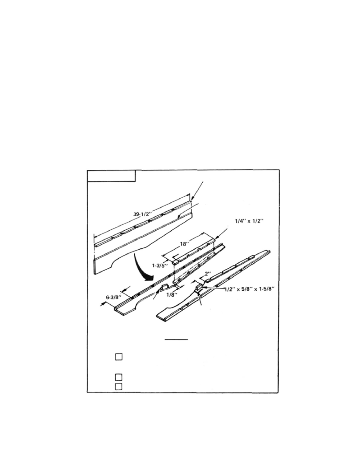
FUSELAGE
RIGHT
FUSELAGE SIDE
F-31
(PLY)
FIG.
1/4" x 1/2" NOTCHED STRIPS
NOTE CURVED TOP EDGE
NOTCHED STRIPS
WING SCREW BLOCK
F-31
(PLY)
LEFT FUSELAGE SIDE
1
HARDWOOD
STEP
1
Glue 1/4 x 1/2 notched balsa strips to fuselage sides. Make a
right and left side. Note: Curve on top edge of fuselage sides is
intentional.
Glue ply braces F-31 to fuselage sides. (See plans for position)
Glue hardwood wing screw blocks in place.
2
Page 5
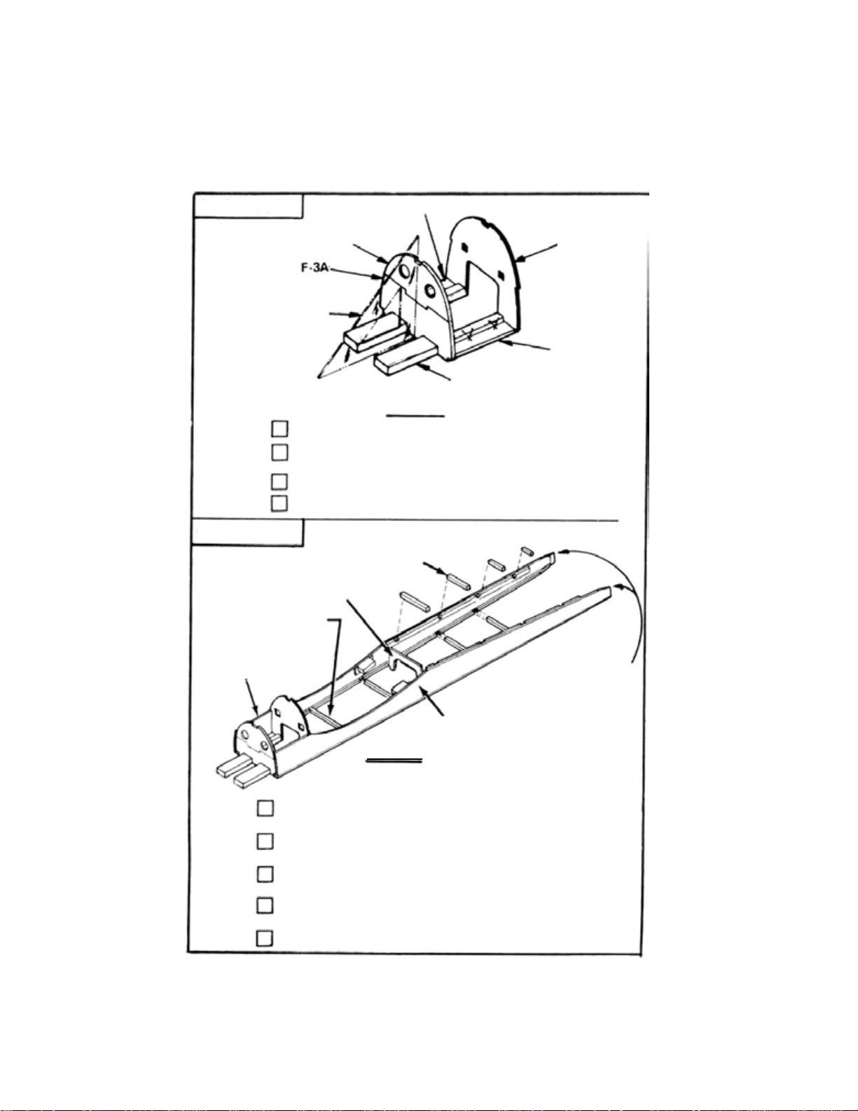
FUSELAGE
F-5
USE TRIANGLE O R
SQUARE TO CHECK
ALIGNMENT.
STEP
2
Glue F-3A and F-3B together.
Pin F-5 spacers over bottom view of plans BETWEEN F-3AB
and F-7.
Glue motor mounts to the two F-5's.
Glue F-3AB assembly and F-7 (ply) vertical in position.
FUSELAGE
F-17
(PLY)
BULKHEAD SPACER
FOR
F-8
F-3B
FIG.
1/4" SQ. SPACERS
F-7
F-5SPACERS
HARDWOOD MOTOR MOUNTS
2
(PLY)
MOTOR MOUNT
ASSEMBLY
STEP
3
Using bottom view of plans, cut 1/4 SQ. bulkhead spacers from
1/4 x 1/4 x 36 balsa strips.
Glue MOTOR MOUNT ASSEMBLY to fuselage sides over
bottom view of plans.
Starting with bulkhead spacer for F-8, glue and pin spacers in
place, working toward rear.
Glue F-17 (ply) in place. (Check plans for position). Hold
fuselage sides together with tape if necessary.
Trim rear, glue, and clamp together.
FIG.
TRIM TO 1/8" EACH
SIDE, GLUE, AND
CLAMP TOGETHER
FUSELAGE SIDE
3
3
Page 6

FUSELAGE
1/4" x 15" SO . S T RI P S
CARDBOARD
COOLING TUBES
FIG.
15"
4
STEP
4
Cut two 1/4 SQ. strips to 15" and glue on top of notched strips
flush with the inside edge. Refer to fuselage cross SECTION B-B.
Using pattern on plans, cut 2 cardboard cooling tubes to size
and glue in place.
FUSELAGE
1/4" x 1/2"
BACKBONE
STEP
5
1/4" x 1/2" BACKBONE.
F
F-19
F-24
F-22
F20
FIG.
5
Glue bulkheads F-19, F-20, F-22, F-24, and F-26 in place.
Note angle of F-19 on plans.
Fit and cut 1/4 x 1/2 backbones to length and glue in place.
4
26
Page 7

GENERAL INSTRUCTIONS
FITTING SHELLS
TOP SHELL
BOTTOM SHELL
TRIM OFF HERE
CENTER EDGE
BOTTOM EDGE
FIG.
6
CENTER EDGE
BOTTOM EDGE
TRIM OFF HERE
CUT ALONG CENTER
BOTTOM EDGE
FIG.
7
HOLD IN PLACE WITH TAPE
Extensive effort has gone into the development of the shells
provided in this kit. Occasionally one shell may split or crack due
to rough treatment during shipment. If this occurs it can easily
be repaired with glue. Each shell is purposely oversize. This is to
allow you enough wood to work with and attain a perfect fit.
When fitting, cut small portions at a time. Trim the shells as in
FIG.
6.
When fitting a shell, lay it lengthwise on it's BOTTOM EDGE.
If it is not flush, sand it until it is. Tape or pin it in place and
cut along the top center. Do the same with the opposite side.
When both shells fit properly, glue them in place. Masking tape
works well in holding them while drying.
5
Page 8

FUSELAGE
F-7
p-19
HARDWOOD
TAIL
BLOCK
BALSA
TAIL
BLOCK
F-26
F-3AB
FORWARD SHELL SECTION
STEP
6
Cut and fit the REAR SECTIONS and glue in place.
Glue the tail blocks in place.
Trim and fit forward shell sections. DON'T GLUE IN PLACE
YET.
FUSELAGE
COCKPIT
ASSEMBLY
P-9
P-12
F-13R
F-10
REAR SECTION
SET CENTER SECTION ASIDE
FIG.
8
F-14
F-13L
F-15
2"
STEP
7
FIG.
F-11
Glue F-13R and F-13L together.
Glue F-11 to bottom part of F-9.
Glue F-15 to bottom part of F-16.
Glue F-13R L assembly on top edges of F-11 and F-15.
Glue F-10 and F-14 on top of F-13 RL.
Glue F-12 2" behind F-10.
6
9
Page 9

FUSELAGE
F-4
1/4" x 1/2" BACKBONES.
COCKPIT ASSEMBLY
F25
F-23
1/4" x 1/4"
x 33-1/2"
STRIPS
F-2
STEP
8
FUSELAGE
TOP RIGHT
FUSELAGE SHELL
F27
F-8
F6
F-18
NOTCH STRIP
FIG.
10
Glue F-27'S to rear of fuselage.
Cut and glue 1/4 x 1/4 x 33-1/2 strips to inside half of
NOTCHED STRIPS. See fus cross section A-A.
Glue COCKPIT ASSEMBLY in place.
Glue bulkheads F - 2 thru F-25 in place.
Cut and glue 1/4x1/2 backbones in place.
F21
TRIM REAR
OF F-27'S
TO
1/4"
THICKNESS
STEP
9
TOP LEFT
FUSELAGE SHELL
FIG.
11
Trim, fit, and glue top fuselage shells in place.
7
Page 10

WING
3/32" x 4" x 30" BALSA SHEETS
FIG.12
STEP
1
WING
Join three 3/32 x 4 x 30 balsa sheets using masking tape as
shown.
Turn over and glue joints as shown.
Pin to a flat surface and allow to dry.
Remove tape.
Make 4 SETS of panels.
PLY
W-13
W-5
W-3
W-2
W-2A
FIG.
13
STEP
2
Glue balsa half rib W -2A to R IB W-2.
Glue landing gear brace W -13 (PLY) to ribs W-3 and W-5
Make sets for RIGHT WING half and LEFT WING half.
8
Page 11

WING
1/2" x 5/8" x 3" BALSA BLOCK
CUTTING LINE
STEP
3
WING
WING TIP END
TOP VIEW
MACHINED BALSA
TRAILING EDGE
FIG.14
Glue 1/2 x 5/8 x 3 balsa blocks to trailing edges as shown.
Place above assembly over wing plan and cut ANGLE in center
so the two will be flush when joined later. Make sure both
trailing edges are equal length after trimming.
TRAILING EDGE ASSEMBLY
WIDE END
WING ALIGNMENT WEDGE
NARROW END
OF WEDGE AT TIP
STEP
4
FIG.15
Pin wing ALIGNMENT WEDGE to plans over location o f
machined trailing edge.
Pin trailing edge assembly over wing alignment wedge. (Do
not glue)
9
Page 12

WING
W-11
W-10
W-14
1/4" x 1/2" TOP SPAR
(PLY)
MARK
W-15
(PLY)
,W.2
W-1
STEP
5
WING
1/4" x 1/2"
BOTTOM SPAR
Pin 1/4 x 1/2 BOTTOM SPAR over plans.
Glue brace W-15 (ply) to front of bottom spar.
Glue AL L RIBS in place over bottom spar.
Glue W-14 (ply) to top spar.
Glue TOP SPAR in place.
Glue LEADING EDGE in place.
Mark leading edge at W -2 for location of wing dowel
FIG.
17
W-6
FIG.
16
NARROW END
WING ALIGNMENT WEDGE
STEP
6
Switch wing alignment wedge to right side.
Block left wing up 4-1/2 under tip.
Construct right half in the same manner as the left.
Glue the two wing halfs together.
10
Page 13

WING
STEP
7
ALIGNMENT WEDGE
FIG.
18
Remove pins from spar and cover the top of right wing with
sheets prepared in Step 1. Allow to dry.
Switch wing alignment wedge back to left side, block right half
up 4-1/2, and sheet the top of the left side.
Allow to dry completely.
WING
LANDING GEAR
KEY BLOCK
LANDING GEAR
BLOCKS
WING TIP
AILERON BELLCRANK
ASSEMBLY
NOTE: IF RETRACTABLE LANDING GEAR IS TO BE USED,
FOLLOW INSTALLATION INSTRUCTIONS PROVIDED BY
GEAR MFG.
STEP
8
HARDWOOD WING
DOWELS
Install
LANDING
holes for gear strut.
Drill
1/4
holes
in
Install aileron bellcrank assembly and aileron pushrod wires.
(See wing cross SECTION CC)
Sheet both bottom halfs marking location for landing gear.
Glue wing TIPS and FLAPS in place.
Glue fabric reinforcing TAPE to center section.
Sand ailerons to final shape. Glue W-16 (ply) insert in place in
each aileron.
REINFORCE CENTER WITH FABRIC
TAPE AFTER SHEETING
FLAPS
W-16 (PLY)
INSERT
GEAR BLOCKS and key
leading
edges and
install
FIG.
hardwood
19
blocks.
AILERON
Drill
5/32
dowels.
11
Page 14

WING
WING SHELL
1/4" x 1/2" BACKBONE
F-32
(PLY)
F-7
(PLY)
W-17
HOLD WIN G IN PLACE WITH
NAIL WHILE DRILLING OPPOSITE
SIDE
W-20
F-29
F-28 FILLET
F-30
(PLY)
MAKE CUTS WITH
RAZOR SAW
STEP
9
FIG.
20
Place wing on fuselage. Put braces F-32 (ply) over wing dowel:
and glue to bulkhead F-7 (ply). DON'T GLUE DOWELS.
Drill
1/8
holes in wing and
Remove wing and tap threads in hold down block with NO. 8
SELF TAPPING SCREW SUPPLIED.
Glue fillet base F-30 (ply) to fuselage and replace wing,
holding with nylon screws. (Protect with monokote backing)
Glue fillets F 28 and fillet ends F-29 in place.
Glue formers W-17, W-18. W-19. and W-20 to wing bottom.
Glue 1/4 x 1/2 backbone in place.
Fit and glue SHE LLS to wing bottom.
Cut notch in shells for access to wing screws.
Fit and glue shells to bottom front of fuselage.
12
hold
down block
for
wing
screws.
Page 15

COWL ASSEMBLY
SAND EDGES
WOOD SCREWS
COWL RING
Sand edges of F-1 (ply) to fit losely inside plastic rear COWL
RING.
Glue F-1 (ply) to fuselage and sand entire fuselage to final shape.
Mount cowl ring to fuselage with wood screws.
Align and glue cowl sections together as shown with model
cement (ambroid, sigment, etc.)
Remove assembled cowl and sand lightly with 400 grit paper.
Mak e CUT-OUTS for exhaust and glow pl u g access.
Cowl will accept most common model paints available in your
local hobby shop. Paint as desired.
FIG.
21
COWL RING
r-1
(Ply)
FIG.22
EXHAUST CUT OUT
TO SUIT ENGINE
TAIL
ASSEMBLY
TOOTHPICK
Join elevators with 1/ 4 x
1/2x4 hardwood strip.
Glue HORIZONTAL
STABILIZER to fuselage body.
Glue FIN on top of horizontal
stabilizer.
Shape and glue balsa STAB
FILLETS in place.
Attach landing gear cover W-21 (ply) to landing gear strut.
Trim excess from canopy. Attach after covering fuselage.
Attach plastic scoop t o bottom rear of fuselage. (See plans for
location)
NYLON
HINGE
ELEVATOR
WOOD SCREWS
13
FIN
STAB FILLETS
HORIZONTAL STABILIZER
1/4"x 1/2" HARDWOOD
ELEVATOR JOINER
FIG.
23
RUDDER
Page 16

COVERING
Sand the entire airplane with 200 grit paper. Then final sand with 400 or 500 grit
paper. Remove all sanding dust with a clean cloth and cover model. A very realistic finish for this model can be obtained with MONOKOTE. This material can be
scratched and textured to look like the skin on the actual P-47. Try to have the
seams along rivet lines, panels, etc. and they will be unnoticeable.
FINAL STEPS
Install the R/C equipment, hinge control surfaces, install engine, fuel tank, wheels,
and push rods using the plans for location. Make sure PLANE BALANCES at or
slightly forward of the CENTER 01 GRAVITY shown on plans, NOTE: THE
FAILURE TO BALANCE THE COMPLETED MODEL AS SHOWN WITH ALL
RADIO GEAR INSTALLED MAY MAKE THE MODEL UNCONTROLLABLE
IN FLIGHT RESULTING IN POSSIBLE INJURY TO OTHERS, TO YOURSELF
OR TO PROPERTY DAMAGE. Make sure all controls work freely, with no binding
and in the proper direction. Carefully follow all installation and operation instructions given by th e radio c ontrol unit manufacturer.
FIRST FLIGHT
It is CRUCIAL that a well-experienced R/C Modeler-Pilot go over the plane carefully
before attempting the first flight. If you are not well-experienced in checking out all
construction and operating details and in flying, GET HELP. R/C modelers are a fine
group of people that will gladly offer help when asked. Your hobby dealer may also
be able to assist you. Write (and join!) the Academy of Model Aeronautics, 806
Fifteenth
Clubs in your state and you can contact one of them. They will be happy to help.
The well-experienced R/C modeler-pilot will thoroughly go over all aspects of your
construction and gear installation. He will then re-check everything at the flying
field and then, if-but only if-all is right, he will perform the all important first
flight of your aircraft and "trim it out", that is, make in-flight adjustments of the
moving surfaces and make further changes on the ground, as necessary. Remember
that even experienced R/C pilots tu rn to really well-experienced modeler-pilots
for this crucial final check-out and trim-flight.
What is at stake is not just your model, but the SAFETY of others, yourself and
property. Do Not fly until you are certain you are flying a checked-out model that
you can SAFELY control under all circumstances!
St.,
N.W.,
Washington,
D.C.
20005.
They
will
supply
you
with a
list
of
R/C
We believe that we have passed on to you some helpful ideas gathered from our own
experience and sincerely hope that building and flying your P-47 will be a rewarding
experience.
Best of Luck!
TOP FLITE MODELS
FLIGHT LOG
14
 Loading...