


 Loading...
TOPFIELD
TF 7700 HD PVR TF 7710 HD PVR
User Guide
High Definition
Digital Satellite Receiver
Personal Video Recorder
The lighting flash with arrowhead symbol, within an equilateral triangle, is intended to alert the user to the presence of uninsulated “dangerous voltage” within the product’s enclosure that may be of sufficient magnitude to consititute a risk of electric shock to a person.
The exclamation point, within an equilateral triangle, is intended to alert the user to the presence of important operating and maintenance (servicing) instructions in the literature accompanying the product.

iv Contents
Contents
Contents |
|
iv |
|
1 Introduction |
1 |
||
1.1 |
Features . . . . . . . . . . . . . . . . . . . . . . . . . . . . . . . |
1 |
|
1.2 |
Controlling the digital receiver . . . . . . . . . . . . . . . . . . |
2 |
|
|
1.2.1 |
The front panel . . . . . . . . . . . . . . . . . . . . . . . |
3 |
|
1.2.2 |
The remote control . . . . . . . . . . . . . . . . . . . . . |
4 |
1.3 |
What is common interface? . . . . . . . . . . . . . . . . . . . . |
6 |
|
2 Setup |
8 |
|
2.1 |
Unpacking . . . . . . . . . . . . . . . . . . . . . . . . . . . . . . |
8 |
2.2 |
Safety precautions . . . . . . . . . . . . . . . . . . . . . . . . . |
8 |
2.3 |
Rear panel connections . . . . . . . . . . . . . . . . . . . . . . . |
10 |
2.4 |
Connecting up your digital receiver . . . . . . . . . . . . . . . |
12 |
|
2.4.1 Connecting the antenna . . . . . . . . . . . . . . . . . . |
12 |
|
2.4.2 Connecting to your television set . . . . . . . . . . . . |
13 |
|
2.4.3 Connecting to your video cassette recorder . . . . . . . |
16 |
2.5 |
Switching on for the first time . . . . . . . . . . . . . . . . . . . |
16 |
|
2.5.1 Inserting batteries in the remote control . . . . . . . . . |
17 |
|
2.5.2 Powering on and checking picture . . . . . . . . . . . . |
17 |
3 Preference Settings |
18 |
|
3.1 |
Language settings . . . . . . . . . . . . . . . . . . . . . . . . . . |
18 |
3.2 |
Video and audio settings . . . . . . . . . . . . . . . . . . . . . . |
20 |
|
3.2.1 Colour model . . . . . . . . . . . . . . . . . . . . . . . . |
20 |
|
|
|
Contents |
v |
|
|
3.2.2 |
Video cassette recorder . . . . . . . . . . . . . . . . . . |
21 |
|
|
3.2.3 |
Television aspect ratio . . . . . . . . . . . . . . . . . . . |
21 |
|
|
3.2.4 |
High definition television . . . . . . . . . . . . . . . . . |
22 |
|
|
3.2.5 |
Audio mode . . . . . . . . . . . . . . . . . . . . . . . . |
23 |
|
3.3 |
Local time setting . . . . . . . . . . . . . . . . . . . . . . . . . . |
23 |
|
|
3.4 |
Parental control . . . . . . . . . . . . . . . . . . . . . . . . . . . |
24 |
|
|
3.5 |
Adjusting the on-screen display . . . . . . . . . . . . . . . . . . |
27 |
|
|
3.6 |
To turn on the time shift feature . . . . . . . . . . . . . . . . . . |
27 |
|
4 |
Service Search |
28 |
||
|
4.1 |
Searching broadcasting services . . . . . . . . . . . . . . . . . . |
28 |
|
|
|
4.1.1 |
Configuring LNB settings . . . . . . . . . . . . . . . . . |
28 |
|
|
4.1.2 Configuring DiSEqC 1.2 settings . . . . . . . . . . . . . |
31 |
|
|
|
4.1.3 |
Configuring USALS settings . . . . . . . . . . . . . . . |
32 |
|
|
4.1.4 |
Searching services . . . . . . . . . . . . . . . . . . . . . |
34 |
|
4.2 |
Copying services . . . . . . . . . . . . . . . . . . . . . . . . . . |
37 |
|
|
4.3 |
Editing the transponder list . . . . . . . . . . . . . . . . . . . . |
37 |
|
|
4.4 |
Resetting to factory settings . . . . . . . . . . . . . . . . . . . . |
38 |
|
5 |
Daily Usage |
|
39 |
|
|
5.1 |
Volume control . . . . . . . . . . . . . . . . . . . . . . . . . . . |
39 |
|
|
5.2 |
Watching television . . . . . . . . . . . . . . . . . . . . . . . . . |
39 |
|
|
|
5.2.1 |
The services list . . . . . . . . . . . . . . . . . . . . . . . |
39 |
|
|
5.2.2 The favourite services list . . . . . . . . . . . . . . . . . |
42 |
|
|
|
5.2.3 |
Viewing programme information . . . . . . . . . . . . |
43 |
|
|
5.2.4 |
Selecting audio tracks . . . . . . . . . . . . . . . . . . . |
44 |
|
|
5.2.5 |
Selecting subtitle tracks . . . . . . . . . . . . . . . . . . |
44 |
|
|
5.2.6 |
Viewing teletext . . . . . . . . . . . . . . . . . . . . . . |
44 |
|
5.3 |
Viewing electronic programme guide . . . . . . . . . . . . . . |
45 |
|
|
5.4 |
Watching multifeed programme . . . . . . . . . . . . . . . . . |
46 |
|
|
5.5 |
Using time shift . . . . . . . . . . . . . . . . . . . . . . . . . . . |
46 |
|
6 |
Listing Services |
48 |
||
|
6.1 |
Editing the services list . . . . . . . . . . . . . . . . . . . . . . . |
48 |
|
|
6.2 |
Editing the favourite list . . . . . . . . . . . . . . . . . . . . . . |
50 |
|
|
6.3 |
How to use on-screen keyboard . . . . . . . . . . . . . . . . . . |
52 |
|

vi Contents
|
6.4 |
Transferring receiver data . . . . . . . . . . . . . . . . . . . . . |
52 |
|
|
6.5 |
Editing channel data on your computer . . . . . . . . . . . . . |
53 |
|
|
|
6.5.1 Editing satellite and transponder list . . . . . . . . . . |
55 |
|
|
|
6.5.2 Editing television and radio services list . . . . . . . . |
57 |
|
|
|
6.5.3 |
Editing favourite list . . . . . . . . . . . . . . . . . . . . |
58 |
7 |
Recording and Playing |
60 |
||
|
7.1 |
Recording a programme . . . . . . . . . . . . . . . . . . . . . . |
60 |
|
|
|
7.1.1 |
Instant recording . . . . . . . . . . . . . . . . . . . . . . |
61 |
|
|
7.1.2 |
Timer recording . . . . . . . . . . . . . . . . . . . . . . |
63 |
|
|
7.1.3 Scheduling recordings using the programme guide . . |
65 |
|
|
|
7.1.4 Recording a pay service programme . . . . . . . . . . . |
66 |
|
|
7.2 |
File archive . . . . . . . . . . . . . . . . . . . . . . . . . . . . . |
67 |
|
|
|
7.2.1 To delete a recording . . . . . . . . . . . . . . . . . . . . |
67 |
|
|
|
7.2.2 |
To sort recordings . . . . . . . . . . . . . . . . . . . . . |
67 |
|
|
7.2.3 To lock a recording . . . . . . . . . . . . . . . . . . . . . |
68 |
|
|
|
7.2.4 To rename a recording . . . . . . . . . . . . . . . . . . . |
68 |
|
|
|
7.2.5 To make a new folder . . . . . . . . . . . . . . . . . . . |
68 |
|
|
|
7.2.6 To move a recording to another folder . . . . . . . . . . |
68 |
|
|
7.3 |
Playing back a recording . . . . . . . . . . . . . . . . . . . . . . |
69 |
|
|
|
7.3.1 To navigate using the progress bar . . . . . . . . . . . . |
69 |
|
|
|
7.3.2 To play in slow motion . . . . . . . . . . . . . . . . . . |
70 |
|
|
|
7.3.3 To play in fast motion . . . . . . . . . . . . . . . . . . . |
70 |
|
|
|
7.3.4 To make a bookmark . . . . . . . . . . . . . . . . . . . . |
71 |
|
|
|
7.3.5 To play back a recording repeatedly . . . . . . . . . . . |
71 |
|
|
|
7.3.6 To play back recordings in sequence . . . . . . . . . . . |
72 |
|
|
|
7.3.7 To play back a scrambled recording . . . . . . . . . . . |
72 |
|
|
7.4 |
Copying a recording . . . . . . . . . . . . . . . . . . . . . . . . |
73 |
|
|
7.5 |
Copying a file from the USB memory into the digital receiver |
73 |
|
|
7.6 |
MP3 playback . . . . . . . . . . . . . . . . . . . . . . . . . . . . |
74 |
|
|
7.7 |
DivX playback . . . . . . . . . . . . . . . . . . . . . . . . . . . . |
75 |
|
|
7.8 |
Formatting the hard disk . . . . . . . . . . . . . . . . . . . . . . |
75 |
|
8 |
Firmware Update |
76 |
||
|
8.1 |
Checking the firmware information . . . . . . . . . . . . . . . |
76 |
|
|
8.2 |
From a USB memory . . . . . . . . . . . . . . . . . . . . . . . . |
77 |
|

|
Contents |
vii |
8.3 |
From the firmware server via the Internet . . . . . . . . . . . . |
78 |
8.4 |
From your computer via RS-232 port . . . . . . . . . . . . . . . |
79 |
8.5 |
From another digital receiver via RS-232 port . . . . . . . . . . |
79 |
8.6 |
Over the air . . . . . . . . . . . . . . . . . . . . . . . . . . . . . |
80 |
Index |
|
82 |

1
Chapter 1
Introduction
The TF 7700 HD PVR/TF 7710 HD PVR digital receiver is fully compliant with the international Digital Video Broadcasting (DVB) standard, and thus is able to receive digital broadcasts of that standard. For its operation you need an antenna, which must be installed appropriately.
NOTE
In general we equate a channel with a frequency. Unlike analogue broadcasts, however, digital broadcasts are not all assigned to their own frequencies; instead, multiple television broadcasts are transmitted through a single frequency. The frequency in digital broadcasting is usually called transponder. To reduce confusion in this manual, the word service is preferably used than channel as a term to indicate one television or radio broadcast.
1.1Features
The TF 7700 HD PVR/TF 7710 HD PVR digital receiver has the following features:

2 Introduction
•Supports DiSEqC 1.0, DiSEqC 1.1, DiSEqC 1.2 and USALS.
•Can store up to 5000 television and radio services.
•You can edit the services list.
•You can create favourite lists of your favourite services.
•You can view information about the current television or radio programme.
•Has an electronic programme guide that provides an overview of scheduled programmes.
•You can record one service while you are currently watching another.
•The large storage capacity of the hard disk drive allows you to record up to about 60 hours of television —in case of 250 gigabytes— in excellent picture and sound quality.
•Time shift is a special technical feature available on the TF 7700 HD PVR/TF 7710 HD PVR. You can pause the programme you are watching and resume it again at a later time. Then you can quickly go to whatever part of the current programme by fast foward or backward search.
1.2Controlling the digital receiver
You can operate the digital receiver with the remote control and the buttons on the front panel.
NOTE
When the digital receiver is off but plugged into a wall outlet, we say that it is in standby mode; on the other hand, when it is on, it is in operation mode. Even when you are not using the digital receiver, you should keep it plugged into a wall outlet to be in standby mode so that it can run timer events at any time.
1.2 Controlling the digital receiver 3
1.2.1 The front panel
The front panel of the digital receiver has buttons to control the digital receiver, and specific lamps and a display to indicate its status. The following indicates what they mean.
button switches the digital receiver between standby mode and operation mode.
VOLUME , + buttons decrease or increase the volume.
They are also used to change values for menu options.
CHANNEL , + buttons switch to previous or next service. They are also used to navigate in menus and interactive screens.
Front display displays the current time in standby mode, and displays the current service in operation mode.
Pull the right edge of the front panel to open the flap. There is a USB port on the front panel for firmware update and data transfer. You have to insert your subscription card into the front slot to watch pay services.

4 Introduction
1.2.2 The remote control
1 |
4 |
15 |
|
14 |
18 |
7 |
|
6 |
10 |
11 |
13 |
12 |
5 |
20 |
17 |
8 |
|
3 |
3 |
21 5
5  32
32

 33
33 27
27

 26
26  22
22

 23
23  19
19 

 30
30  16
16 

 37
37
9
 34
34 

 35
35


 28
28  25
25 

 24
24  29
29


 36
36  31
31
2
1  button switches the digital receiver between standby mode and operation mode.
2  is used to set a sleep timer in 10 minute increments.
3 b, d buttons decrease or increase the volume. They are also used to change values for menu options.
4  mutes the sound. Press again to switch it back on.
5 c, a buttons switch to previous or next service. They are also used to navigate in menus and interactive screens.
6  switches between the current service and the previously viewed one.
7 Numeric buttons are used to enter a service number for service change orto specify values for menu options.
8 OK displays the services list. See § 5.2.1 for more details. It is also usedto select a menu item.
9 FAV displays the favourite lists.
10  displays the service information box. It is also used to display more information about a programme.
11  is used to select an audio track and a sound mode, or a video track of multifeed programme.

|
|
|
|
|
|
|
|
|
|
|
|
|
1.2 Controlling the digital receiver 5 |
|
|
|
|
|
|
is used to select a subtitle track. |
|
||||||||
12 |
|
|
|
|
|
|
|
|
|
|
|
|
|
|
|
|
|
|
|
displays teletext. |
|||||||||
13 |
|
|
|
|
|
|
|
|
|
|
|
|
|
|
|
|
|
|
|
|
|
|
|
|
|
|
|||
|
|
|
|
|
|
|
|
|
|
|
||||
|
|
|
|
|
|
|
|
|
|
changes video resolution. See § 3.2.4 for more |
||||
14 |
|
V.Format |
|
|
||||||||||
|
details. |
|
|
|||||||||||
|
|
|
|
|
|
|
|
|
|
|
|
|
||
|
|
|
|
|
|
|
|
|
|
|
||||
|
|
changes aspect ratio. See § 3.2.3 for more details. |
||||||||||||
15 |
|
A/R |
|
|
|
|
|
|
|
|
|
|
||
|
|
|
|
|
switches between television services and radio ser- |
|||||||||
16 |
|
|
|
|
|
|
|
|
|
|
|
|
|
|
|
vices. |
|
|
|
|
|||||||||
|
|
|
|
|
|
|
|
|
|
|
|
|
||
|
|
|
|
|
|
|
|
|
||||||
|
|
|
|
|
|
|||||||||
|
|
|
|
|
|
|||||||||
|
|
|
displays the electronic programme guide. |
|||||||||||
|
|
|
|
|
|
|
|
|||||||
17 |
|
GUIDE |
|
|
|
|
|
|||||||
|
|
|
|
|
|
|
|
|
|
|
||||
|
|
|
|
|
|
|
|
|
|
|||||
|
|
|
|
|
|
|
|
|||||||
18 |
|
AUX |
|
|
|
switches the output of the TV SCART socket be- |
||||||||
|
tween the digital receiver and the device connected to |
|||||||||||||
|
the VCR SCART socket. See § 3.2.2 for more details. |
|||||||||||||
|
|
|
|
|
|
|
|
|
|
|
|
|||
|
|
|
|
|
|
|
|
|
||||||
|
|
|
displays the satellites list with their services list. |
|||||||||||
19 |
|
SAT |
|
|
|
|
|
|
|
|
||||
|
|
|
|
|
|
|
|
|
|
|
||||
|
|
|
|
|
|
|
|
|||||||
|
|
|
|
|
|
displays the main menu. It is also used to return |
||||||||
20 |
|
MENU |
|
|
|
|
|
|||||||
|
to the previous menu from a submenu. |
|||||||||||||
22 |
|
|
|
|
|
|
|
|
|
|
||||
|
|
|
|
|
is used to exit the current screen. |
|||||||||
21 |
|
EXIT |
|
|
|
|
|
|
|
|
||||
|
|
|
is used to start recording. |
|||||||||||
|
|
|
|
|||||||||||
23 |
|
|
|
is used to stop playback, to stop recording, or to jump |
||||||||||
|
|
|
|
|||||||||||
back to live television from time-shifted television.
24  is used to display the list of recorded programmes that are stored on the internal hard disk drive. See § 7.2 for more details.
25  resumes normal playback speed, or displays the progress bar for navigation on playback or time shift. To play a recorded programme, see button 24.
26  pauses live television or playback of a recorded programme.
27  is used to start reverse playback. Subsequent presses increase the rewind speed.
6 Introduction
28 |
|
|
|
|
|
|
|
is used to start fast motion playback. Subsequent |
|||||
|
|
|
|
|
|
|
|
||||||
|
presses increase the playback speed. |
||||||||||||
29 |
|
|
|
|
|
is used to start slow motion playback. Subsequent |
|||||||
|
|
|
|
|
|
||||||||
|
presses change the playback speed. |
||||||||||||
30 |
|
|
|
|
is used to jump back to beginnng of recording during |
||||||||
|
|
|
|
|
|||||||||
|
a playback. |
|
|||||||||||
31 |
|
|
|
|
is used to jump to end of recording during a playback. |
||||||||
|
|
|
|
|
|||||||||
32 |
|
|
|
|
|
|
has different functions per menu. |
||||||
|
|
|
|||||||||||
33 |
|
|
|
|
|
|
is used to make a bookmark during playback or time |
||||||
|
|
|
|
|
|
|
|
|
|
|
|
|
|
|
|
|
|
|
|
|
|
||||||
|
shift. |
|
|
|
|
|
|||||||
|
|
|
|
|
|
|
|
|
|
||||
34 |
|
F3 |
|
|
|
is used to jump to next bookmark position or to jump |
|||||||
|
|
||||||||||||
|
forward 30 seconds. |
||||||||||||
|
|
|
|
|
|
|
|
|
|
||||
35 |
|
|
|
|
|
|
is used to jump back 20 seconds for an instant replay. |
||||||
|
|
|
|||||||||||
|
|
|
|
|
|
|
|
|
|
|
|
|
|
36 |
|
|
has different functions per menu. |
||||||||||
|
|
|
|
|
|
|
|
|
|||||
|
|
|
|
|
|
|
|
|
|
|
|
|
|
37 |
|
|
|
|
|
|
|
is used to display the list of files that are stored on |
|||||
|
|
|
|
|
|
|
|
||||||
|
the USB memory stick. For more details, refer to § 7.5 |
||||||||||||
The |
|
|
|
, |
|
, |
|
, |
|
and buttons have additional different |
|||
|
|
|
|
F3 |
|
||||||||


functions per menu besides their own function. They will be guided by on-screen help.
1.3What is common interface?
Some broadcasts are scrambled so that only paid subscribers can enjoy them. Scrambled services can only be viewed with a Conditional Access Module (CAM) and a subscription card belonging with the scrambling system.
Common Interface (CI) is the slot on a digitial receiver into which a conditional access module may be insterted. The front of the digital receiver has two common interfaces.
1.3 What is common interface? 7
To watch a pay service, you should take the following steps:
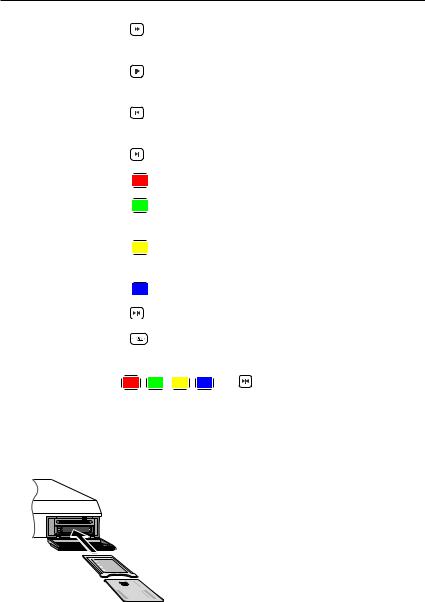
1.Purchase a conditional access module and a subscription card for the pay service you want to watch.
2.Insert the subscription card into the conditional access module.
3.Insert the conditional access module into a common interface on the front of the digital receiver.
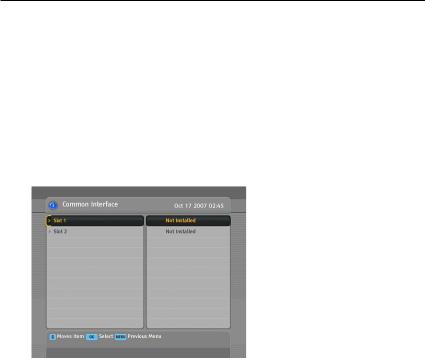
To view the information about the module and subscription card which is inserted into the digital receiver, select the Information > Common Interface menu. You should see a screen like the left figure.

8 Setup
Chapter 2
Setup
2.1Unpacking
Before going any further, check that you have received the following items with your digital receiver.
•Remote control unit
•Two batteries for the remote control (AAA 1.5 V)
•One power cord
•One HDMI cable
•A copy of this user guide
NOTE
Accessories may vary according to your local area.
2.2Safety precautions
Please read carefully the following safety precautions.
•The mains power must be 90 to 250 volts. Check it before connecting the digital receiver to the mains socket . For the power consumption of the digital receiver, refer to Table 2.1.

2.2 Safety precautions 9
•The mains socket should be near the equipment. Do not run an extension lead to the unit.
•Do not expose the digital receiver to any moisture. The digital receiver is designed for use indoors only. Use dry cloth when cleaning the digital receiver.
•Place the digital receiver on a firm and level surface.
•Do not place the digital receiver close to heat emitting units or in direct sunlight, as this will impair cooling. Do not lay any objects such as magazines on the digital receiver. When placed in a cabinet, make sure there is a minimum space of 10 centimetres around it. For the physical specification of the digital receiver, refer to Table 2.2.
•Protect the power cord from being walked on or pinched. If the cord is damaged, do not use the digital receiver and get the cord replaced.
•Never open the digital receiver casing under any circumstances, or the warranty will be void.
•Refer all servicing to a qualified service technician.
Table 2.1: Power specifications
Input voltage |
90 to 250 V AC, 50/60 Hz |
Power consumption |
60 W at maximum in operation |
|
7 W in standby |
|
|
Table 2.2: Physical specifications |
|
|
|
Size |
430 60 265 mm |
Weight |
3.8 kg |
Operating temperature |
0 to 45 °C |
Storage relative humidity 5 to 90 %
10Setup
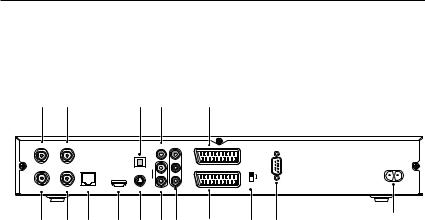
2.3Rear panel connections
The TF 7700 HD PVR/TF 7710 HD PVR has a wide range of connections on the back.
1 |
3 |
|
|
7 |
9 |
12 |
|
|
|
LNB 1 IN |
LNB 2 IN |
|
|
|
VIDEO |
|
|
|
|
|
|
|
|
|
Y |
|
|
|
|
|
|
|
|
L |
Pb |
TV |
SCART |
|
RS-232 |
|
|
|
|
|
|
||||
|
|
|
|
S/PDIF |
|
|
|
|
|
|
|
|
|
R |
Pr |
|
|
|
|
|
|
|
|
|
|
|
YPbPr |
|
|
LNB 1 OUT |
LNB 2 OUT |
LAN |
HDMI |
S-VIDEO |
AUDIO |
VCR |
|
|
|
2 |
4 |
5 |
6 |
8 |
10 11 |
13 |
14 |
15 |
16 |
|
Check what connections your television set has in comparison with the digital receiver.
1 LNB 1 IN Satellite broadcasting signal input socket for the first tuner.
2 LNB 1 OUT Satellite broadcasting signal output socket through the first tuner.
3 LNB 2 IN Satellite broadcasting signal input socket for the second tuner.
4 LNB 2 OUT Satellite broadcasting signal output socket through the second tuner.
LAN |
Local area network port. See § 8.3 |
5 |
|
6 HDMI Audio and video output socket for the high definition television set.
7 S/PDIF Dolby digital output socket for the audio system.
8 S-VIDEO Super video output socket for the television set.

2.3 Rear panel connections 11
9 VIDEO Composite video output socket for the television set. (yellow)
10 AUDIO L/R Stereo audio output socket for the television set or the audio system. (white/red)
11 |
Component video output socket for the tele- |
Y/Pb/Pr |
|
TV |
vision set. (green/blue/red) |
Audio and video output socket for the televi- |
|
12 |
|
VCR |
sion set. |
Audio and video input/output socket for the |
|
13 |
|
|
video cassette recorder or suchlike. |
14 YPbPr $ SCART Video output selection switch. See § 3.2.4 for more details.
15 RS-232 Serial port for firmware update and data transfer.
16 AC INPUT Power socket.
Table 2.3: Connectors specifications
HDMI |
High definition video output |
|
Left & right audio output |
|
Dolby digital audio output |
VIDEO |
Composite video (CVBS) output |
AUDIO |
Left & right audio output |
S-VIDEO |
Super video (S-Video) output |
YPbPr |
Component video (YUV) output |
TV |
CVBS/S-Video/RGB video output |
|
Left & right audio output |
VCR |
CVBS video output |
|
Left & right audio output |
|
CVBS/S-Video/RGB video input for bypass |
|
Left & right audio input for bypass |
S/PDIF |
Dolby digital audio output |
RS-232 |
115.2 kbps at maximum |
USB |
2.0 Host (5 V DC, 500 mA) |
|
|
12Setup
2.4Connecting up your digital receiver
There are several ways to set up the digital receiver. Set up the digital receiver suitably to your television and other appliances. If you have any problem with your setup or need help, contact your dealer.
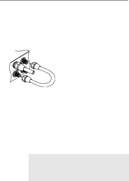
2.4.1 Connecting the antenna
Whatever sort of connection you have between the digital receiver and the television, you need to connect the digital receiver to your television antenna so that it can receive digital television services.
Connect the antenna cable to the LNB 1 IN connector on the back panel of the digital receiver.
Also, you must ensure that there is a connection to both the LNB 1 IN and LNB 2 IN connectors on your digital receiver, so that both tuners work properly.
Normally you do that by using a loop cable to link from the LNB 1 OUT connector to the LNB 2 IN connector.
If you have two antennas without DiSEqC switch, then you have to connect a cable from the other antenna directly to the LNB 2 IN connector rather than using the loop cable. If you have another digital receiver, you may link it from the LNB 2 OUT connector.
NOTE
The digital receiver can supply a current of 500 milliampere at maximum for antenna devices including LNB, DiSEqc switch and antenna rotor through each antenna input connection separately but not simultaneously. If there are too many antenna
2.4 Connecting up your digital receiver 13
devices to be supplied with power through antenna input connections simultaneously for a long time, your LNBs may lack power to operate. So it is recommended to link the LNB 1 OUT connector to the LNB 2 IN connector with a loop cable even though the digital receiver is designed to operate over two antennas alternatively.
NOTE
Perhaps you are expecting that the satellite antenna could simultaneouly catch all frequencies coming from a satellite and send them to the digital receiver. However, the satellite antenna only sends the frequencies that it can catch with the LNB frequency and polarisation specified by the digital receiver. So if you have linked from the LNB 1 OUT connector to the LNB 2 IN connector, you would have some limitations in using some features such as dual recording. Likewise, if you have another digital receiver linked from the LNB 2 OUT connector, you can only use it limitedly. See § 4.1 for more details.
2.4.2 Connecting to your television set
Between all the following connectors of the digital receiver, we recommend you to use the first connector to get best picture quality. If your television does not have the matching connector, then use the next connector in the following order for better picture quality.
1.HDMI connector (HDMI)
2.SCART connector (TV)
3.Component connector (YPbPr)
4.S-Video connector (S-VIDEO)
5.Composite connector (VIDEO)
You should configure audio and video settings after connecting up the digital receiver. See § 3.2 for detailed description.
14 Setup
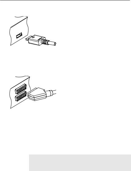
To use the HDMI connector
If you have a high definition television set, you should use a HDMI cable for best results. Plug one end of the cable into the HDMI socket on the digital receiver, and plug the other end into the matching socket on your television. In this case, you do not have to make audio connection because the HDMI connector can output stereo audio or Dolby digital audio.
To use the SCART connector
For best results with a standard television set, you should use a SCART cable. Plug one end of the cable into the TV socket on the digital receiver, and plug the other end into a free SCART socket on your television.
Some televisions have inputs via S-Video or
Component connectors rather than SCART.
If you have such a television, use an appropriate conversion cable to link the TV socket on the digital receiver to the matching socket on your television.
If you connect with a standard SCART cable, you do not have to make audio connection because the SCART connector can output stereo audio. But if you use a conversion cable, such as SCART-to-Component, you have to make audio connection.
NOTE
You cannot view high definition video with the SCART connector.
2.4 Connecting up your digital receiver 15
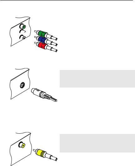
To use the component video connector
Y
Pb 


Pr 

You need to obtain a component video cable (RCA cable) to use the component video connector. Plug one ends of the cable into the Y (green), Pb (blue) and Pr (red) sockets on the digital receiver, and plug the other ends into the matching sockets on your television.
To use the S-Video connector
NOTE
You cannot view high definition video with the S-Video connector.
You need to obtain a S-Video cable to use the S-Video connector. Plug one end of the cable into the S-VIDEO socket on the digital receiver, and plug the other end into the matching socket on your television.
To use the composite video connector
NOTE
You cannot view high definition video with the composite video connector.
You need to obtain a composite video cable (RCA cable) to use the composite video connector. Plug one end of the cable into the VIDEO (yellow) socket on the digital receiver, and plug the other end into the matching socket on your television.
16 Setup
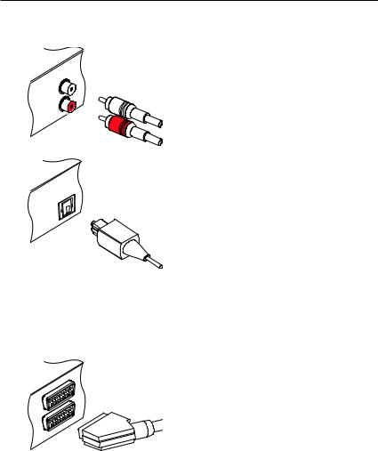
To make the audio connection
You need to obtain an audio cable (RCA cable) to connect the audio connectors. Plug one end of the cable into the AUDIO L (white) and AUDIO R (red) sockets on the digital receiver, and plug the other end into the matching sockets on your television or audio system.
To enjoy Dolby digital audio, your television or audio system must be able to decode Dolby digital audio, and you need to obtain a S/PDIF cable. Plug one end of the cable into the S/PDIF socket on the digital receiver, and plug the other end into the matching socket on your audio system.
2.4.3 Connecting to your video cassette recorder
The digital receiver can also output video to another appliance such as a video cassette recorder through an auxiliary SCART connector.
You need to obtain a SCART cable to use the auxiliary SCART connector. Plug one end of the cable into the VCR socket on the digital receiver, and plug the other end into the matching socket on your video cassette recorder or suchlike.
2.5Switching on for the first time
Now that you have your digital receiver connected, you should plug it into a mains socket. Ensure that your television set is turned on, so that you will be able to see the display from the digital receiver.

2.5 Switching on for the first time 17
2.5.1 Inserting batteries in the remote control
To insert the batteries, open the battery compartment by removing the lid, and then insert the batteries observing the polarity, which is marked on the base of the battery compartment.
If the digital receiver no longer reacts properly to remote control commands, the batteries may be flat. Be sure to remove used batteries. The manufacturer accepts no liability for the damage resulting from leaking batteries.
NOTE
Batteries, including those which contain no heavy metals, may not be disposed of with household waste. Please dispose of used batteries in an environmentally sound manner. Find out about the legal regulations which apply in your area.
2.5.2 Powering on and checking picture
Now, press the  button in top left corner on the remote control. If you do not see a picture, try pressing the V.Format button on the remote control. If after several tries you still get no picture, check that the television is set to the correct input. If the picture is good, you can skip to § 4.1 to search for the available television and radio services. Otherwise, you may need to temporarily connect the composite video connector (VIDEO) to your television set so that you can see the on-screen menus in order to configure the video settings.
18 Preference Settings
Chapter 3
Preference Settings
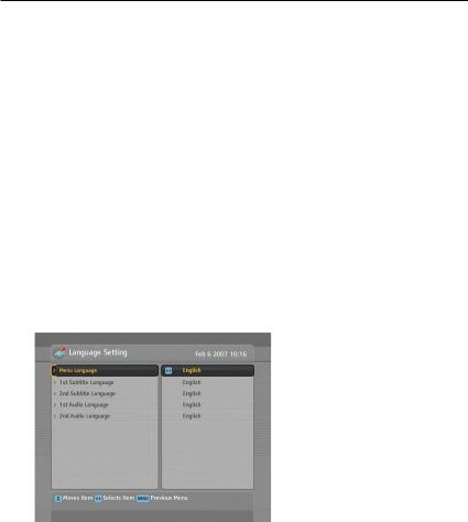
3.1Language settings
You can select the language in which the menu would be displayed. In addition to that, you can select which language of audio track and of subtitle track should be output.
Select the System Setting > Language Setting menu. You should see a screen like the left figure.
Menu language
The digital receiver supports many menu languages: Dutch, English, German, French, Italian, Russian, Turkish and so forth. Set the Menu Language option to your desired language. Once you select a language, the menu will be immediately displayed in the selected language.

3.1 Language settings 19
Subtitle language
Set the 1st Subtitle Language option and the 2nd Subtitle Language option to your desired languages. When you watch a programme, if the programme has a subtitle track of the language that is designated for the 1st Subtitle Language, it will be displayed. If the first language is not available but the second language is available, the subtitle of the second language will be displayed. If there is not any available language, no subtitle will be displayed.
Apart from this setting, you can select a subtitle track with the  button. See § 5.2.5 for detailed description.
Audio language
Set the 1st Audio Language option and the 2nd Audio Language option to your desired languages. When you watch a programme, if the programme has an audio track of the language that is designated for the 1st Audio Language, it will be output. If the first language is not available but the second language is available, the audio of the second language will be output.
Apart from this setting, you can select an audio track with the  button. See § 5.2.4 for detailed description.
20 Preference Settings
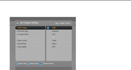
3.2Video and audio settings
You have to configure the video and audio settings appropriately to your television set and other appliances.
Select the System Setting > A/V Output Setting menu. You should see a screen like the left figure.
3.2.1 Colour model
Through the TV SCART connector, the digital receiver is able to output video in various colour models. If you have the digital receiver linked to your television via this connector, you should set the SCART Output option to your desired colour model. If you have connected via the RCA connector labeled VIDEO on the back panel, you do not have to set this option because the digital receiver outputs CVBS video through the RCA connector independent of the SCART connector.
However, if you have connected via the S-VIDEO connector, you have to set this option to S-Video because the output through S-Video connector comes from the SCART interface. Similarly, if you have done by YUV connectors (Y, Pb and Pr), you have to set this option to YUV for the same reason.
It is known in general that the RGB colour model provides the best video quality with little difference from the YUV colour model but the CVBS colour model does the least. So RGB would be most desirable for this option.
3.2 Video and audio settings 21
3.2.2 Video cassette recorder
You can have the digital receiver linked to your video cassette recorder or such an appliance via the VCR SCART connector. In that case, the digital receiver will operate differently depending on the setting of the VCR Scart Type option. If the option is set to Standard, the digital receiver will pass the video from the video cassette recorder to your television when it starts playback. But if the option is set to External A/V, the digital receiver will not pass the video automatically. To pass it, you have to press the AUX button.
NOTE
It is impossible for the digital receiver to record the video that the video recorder plays back because the digital receiver is just a bypass for the video recorder.
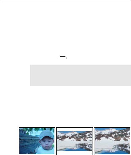
3.2.3 Television aspect ratio
If you have a wide-screen television, set the TV Aspect Ratio option to 16:9.
Otherwise, if you have a normal-screen television, set the TV Aspect Ratio option to 4:3.
You cannot fully enjoy wide-screen programmes with your normal-screen television as the above figures show. The left figure shows a normal picture displayed in the normal screen. To watch wide-screen programmes in the shape like the centre figure, set the 16:9 Display Format option to Letter Box. Widescreen pictures then will be reduced to fit to the width of the
Loading...