


 Loading...
TOPFIELD
TF6000F
User Manual
Digital Satellite Receiver
Free To Air
ii |
CONTENTS |
Contents
Contents |
|
ii |
|
1 Overview |
|
1 |
|
1.1 |
Introduction . . . . . . . . . . . . . . . . . . . . . . . . . . . . |
1 |
|
1.2 |
Controlling The Digital Receiver . . . . . . . . . . . . . . . . . |
2 |
|
|
1.2.1 |
Front Panel . . . . . . . . . . . . . . . . . . . . . . . . |
2 |
|
1.2.2 |
Remote Control . . . . . . . . . . . . . . . . . . . . . . |
3 |
2 Installation |
5 |
|
2.1 |
Packing Contents . . . . . . . . . . . . . . . . . . . . . . . . . |
5 |
2.2 |
Safety Precautions . . . . . . . . . . . . . . . . . . . . . . . . . |
5 |
2.3 |
The Connection Panel . . . . . . . . . . . . . . . . . . . . . . . |
7 |
2.4 |
Connecting The Digital Receiver . . . . . . . . . . . . . . . . . |
7 |
|
2.4.1 Connecting to The Satellite Antenna . . . . . . . . . . |
7 |
|
2.4.2 Connecting to The TV by RCA Cable . . . . . . . . . . |
8 |
|
2.4.3 Connecting to The TV by RF Cable . . . . . . . . . . . |
8 |
2.5 |
Inserting Batteries in The Remote Control . . . . . . . . . . . |
9 |
2.6 |
Station Settings . . . . . . . . . . . . . . . . . . . . . . . . . . |
9 |
|
2.6.1 LNB Setting . . . . . . . . . . . . . . . . . . . . . . . . |
10 |
|
|
|
|
iii |
|
|
2.6.2 |
Service Search . . . . . . . . . . . . . . . . . . . . . . . |
12 |
|
|
2.6.3 |
Motorized DiSEqC 1.2 . . . . . . . . . . . . . . . . . . |
14 |
|
|
2.6.4 |
USALS Setting . . . . . . . . . . . . . . . . . . . . . . . |
15 |
|
|
2.6.5 Editing The Transponder List . . . . . . . . . . . . . . |
17 |
|
|
|
2.6.6 |
Factory Setting . . . . . . . . . . . . . . . . . . . . . . |
19 |
|
|
2.6.7 |
System Recovery . . . . . . . . . . . . . . . . . . . . . |
19 |
3 |
Preference Settings |
20 |
||
|
3.1 |
Time Setting . . . . . . . . . . . . . . . . . . . . . . . . . . . . |
20 |
|
|
3.2 |
Timer Setting . . . . . . . . . . . . . . . . . . . . . . . . . . . . |
21 |
|
|
3.3 |
Access Restriction . . . . . . . . . . . . . . . . . . . . . . . . . |
23 |
|
|
3.4 |
Language Setting . . . . . . . . . . . . . . . . . . . . . . . . . |
24 |
|
|
3.5 |
Audio and Video Setting . . . . . . . . . . . . . . . . . . . . . |
25 |
|
|
3.6 |
Menu Display Transparency . . . . . . . . . . . . . . . . . . . |
26 |
|
|
3.7 |
Display Time of The Information Box . . . . . . . . . . . . . . |
26 |
|
|
3.8 |
Position of The Information Box . . . . . . . . . . . . . . . . . |
26 |
|
4 |
Listing Services |
28 |
||
|
4.1 |
Editing The Services List . . . . . . . . . . . . . . . . . . . . . |
28 |
|
|
4.2 |
Editing The Favorites List . . . . . . . . . . . . . . . . . . . . |
30 |
|
5 |
Daily Usage |
|
31 |
|
|
5.1 |
Browsing Services . . . . . . . . . . . . . . . . . . . . . . . . . |
31 |
|
|
5.2 |
Information Box . . . . . . . . . . . . . . . . . . . . . . . . . . |
32 |
|
|
5.3 |
Electronic Program Guide . . . . . . . . . . . . . . . . . . . . |
33 |
|
|
5.4 |
Viweing Subtitle . . . . . . . . . . . . . . . . . . . . . . . . . . |
34 |
|
|
5.5 |
Viewing Teletext . . . . . . . . . . . . . . . . . . . . . . . . . . |
34 |
|
|
5.6 |
Selecting Sound Track . . . . . . . . . . . . . . . . . . . . . . . |
35 |
|
|
5.7 |
Selecting Multifeed . . . . . . . . . . . . . . . . . . . . . . . . |
35 |
|
iv |
|
|
CONTENTS |
6 |
Firmware Update and Data Transfer |
36 |
|
|
6.1 |
Firmware Update . . . . . . . . . . . . . . . . . . . . |
. . . . . 37 |
|
|
6.1.1 From The Satellite . . . . . . . . . . . . . . . . |
. . . . . 37 |
|
|
6.1.2 From a Personal Computer via RS232 Port . . |
. . . . . 37 |
|
|
6.1.3 From another Digital Receiver via RS232 Port |
. . . . . 38 |
|
6.2 |
Data Transfer . . . . . . . . . . . . . . . . . . . . . . . |
. . . . . 39 |
A |
Information |
40 |
|
|
A.1 |
Operational Functions and Features . . . . . . . . . . |
. . . . . 40 |
|
A.2 |
Technical Specification . . . . . . . . . . . . . . . . . |
. . . . . 41 |
Index |
|
43 |
|

1
Chapter 1
Overview
1.1Introduction
The TF6000F digital receiver is fully compliant with the international digital video broadcasting standard, and can play digital satellite services. To operate it, you need a satellite antenna, which must be installed and directed at the required satellite.
Unlike analogue broadcasting, digital television and radio services are not all assigned their own frequencies; instead, several television and radio are transmitted by a single transponder.
To help you with the choice and settings for satellite services, a selection of television and radio services have already been programmed for you. You can do service search so that all the satellite services that have since gone on air are available to you. Of course, you can easily program new services yourself. You can find the current transponder information on teletext from various broadcasters.
The TF6000F digital receiver has the features as follows:
2 |
Overview |
•This digital receiver supports DiSEqC 1.0, DiSEqC 1.1, DiSEqC 1.2 and USALS (DiSEqC).
•This digtial receiver saves up to 5000 TV and radio services.
•You can edit the service list and make your own favorite service list.
•You can view the program guide
•You can view the information of a TV programme.
•You can update the firmware of the digital receiver to the latest, which will be provided by Topfield.
Refer to Section A.1 on page 40 for detailed features.
1.2Controlling The Digital Receiver
You can control the digital receiver with the remote control and the front panel buttons.
1.2.1 Front Panel
CHANNEL |
 lamp lights up whenever you press a button of the remote control.
PWR lamp lights up while the digital receiver is in the the standby mode.
CHANNEL , buttons switch services up and down, and move the cursor up and down in the menus.
 button toggles the digital receiver between the operation mode and the standby mode.

1.2 Controlling The Digital Receiver |
3 |
1.2.2 Remote Control
|
Standby button toggles the digital re- |
||
|
1 |
|
|
|
|
ceiver between operation mode |
|
|
|
and standby mode. |
|
|
Mute button mutes the television or |
||
|
2 |
|
|
|
|
audio appliance. |
|
|
Numeric buttons selects a |
service to |
|
|
3 |
|
|
|
|
watch, or enters a parameter |
|
|
|
value such as recording time. |
|
|
Recall button makes a return to the |
||
|
4 |
|
|
|
|
previous service. |
|
|
FAV button displays the favorite ser- |
||
|
5 |
|
|
|
|
vice list. |
|
|
Menu button displays the |
menu, or |
|
|
6 |
|
|
|
|
escapes to a higher level menu |
|
|
|
out of a submenu. |
|
|
Exit button escapes from any menu. |
||
|
7 |
|
|
|
Guide button displays |
program |
|
|
8 |
|
|
|
|
guides, if available. |
|
|
Information button displays the infor- |
||
|
9 |
|
|
|
|
mation about the programme on |
|
|
|
the air. |
|
|
, buttons switch services up and |
||
|
10 |
|
|
|
|
down, and move the cursor up |
|
|
|
and down in the menus. |
|
|
, buttons change the volume, and select and change |
||
11 |
|
|
|
individual entries in the menus.
12 OK button displays the service list, and selects an entry in the menus.
13 TV/Radio button toggles between TV mode and radio mode.
4 |
Overview |
14 SAT button displays the satellite list. (available only for the satellite receiver)
15 V+ and V− buttons change the volume, and select and change individual entries in the menus.
16 P+ and P− buttons switch services up and down, and move the cursor up and down in the menus.
17 Function buttons have other functions per menu. Their functions will be guided in the help window on a menu screen.
18 Sound, Subtitle and Teletext button selects sound track and mode, enables subtitle display, and enables teletext display, if available.
19 Pause button keeps a picture from the programme on the air as it is.
20 UHF button displays the RF modulator settings.
21 TV/STB button toggles between digital TV from the digital receiver and analogue TV from the conventional aerial broadcasting.
22 M1 button displays the multipicture selection window. (available only in specific models)
23 N/P button switches the colour encoding method.
24 Sleep button sets the sleep timer. The digital receiver is turned off to standby mode when a specified time is elapsed,

5
Chapter 2
Installation
2.1Packing Contents
Unpack your receiver and check the following cables and accessories are also included in the package:
•1 remote control.
•2 batteries (AAA 1.5 V).
•1 user manual
2.2Safety Precautions
Please read the following safety precautions carefully for your safety.
•The mains supply must be 90 to 250 volt. Check it before connecting the digital receiver to the mains supply.
•This digital receiver is designed to receive, record and play back video and audio signals. Any other use is expressly prohibited.
6 |
Installation |
•When setting up the digital receiver, make sure it is in a horizontal position and that the mains socket is easily accessible.
•Do not expose the digital receiver to any moisture. The digital receiver is designed for use in dry rooms. If you do use it outdoors, please ensure that it is protected from moisture, such as rain or splashing water. Do not place any vessels such as vases on the digital receiver. These may be knocked over and spill fluid on the electrical components, thus presenting a safety risk.
•Do not place the digital receiver close to heating units or in direct sunlight, as this will impair cooling. Place the digital receiver on a hard, level surface. Do not lay any objects such as magazines on the digital receiver. When placed in a cabinet, make sure there is a minimum space of 10 cm around it.
•Thunderstorms are a danger to all electrical devices. Even if the digital receiver player is switched off, it can be damaged by a lightning strike to the mains or the antenna. Always disconnect the mains and antenna plugs during a storm.
•Never open the digital receiver casing under any circumstances. Warranty claims are excluded for damage resulting from improper handling.
2.3 The Connection Panel |
7 |
2.3The Connection Panel
RF OUT
LNB IN
RF IN
|
|
|
|
RS-232 |
R - AUDIO - LVIDEO |
|
LNB OUT |
|
|||
|
|
||||
|
|
|
|
|
|
|
|
|
|
|
|
1)LNB IN: Satellite broadcast input socket.
2)LNB OUT: Satellite broadcast output socket.
3)VIDEO: Composite video output socket for television or AV receiver.
4)R-AUDIO-L: Stereo audio output socket for television or audio appliance.
5)RF IN: Terrestrial broadcast input socket from conventional aerial antenna.
6)RF OUT: AV output socket for television.
7)RS232: Serial port for firmware update and data transfer
2.4Connecting The Digital Receiver
There are some ways to install the digital receiver as described below. Install the digital receiver suitably to your television and audio appliance. If you have problems with your installation or need a help, contact your dealer or service provider.
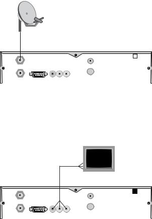
2.4.1 Connecting to The Satellite Antenna
Connect the satellite antenna cable to the LNB IN socket on the digital receiver.
8 |
|
|
Installation |
|
|
|
|
|
|
|
|
|
|
|
|
|
|
|
|
|
|
|
|
|
RF OUT
LNB IN
 RF IN
RF IN
LNB OUT |
RS-232 |
R - AUDIO - LVIDEO |
|
|
|
2.4.2 Connecting to The TV by RCA Cable
Plug a RCA cable into the VIDEO (yellow), L AUDIO (white) and R AUDIO (red) sockets on the digital receiver and the corresponding input sockets on the television or audio appliance.
RF OUT
LNB IN
 RF IN
RF IN
LNB OUT |
RS-232 |
R - AUDIO - LVIDEO |
|
|
|
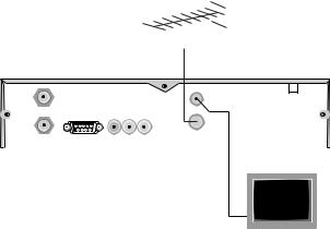
2.4.3 Connecting to The TV by RF Cable
Connect the aerial antenna cable to the RF IN socket on the digital receiver, and then plug a RF cable into the RF OUT socket on the digital receiver and the corresponding input socket on the television.
2.5 Inserting Batteries in The Remote Control |
9 |
|||||
|
|
|
|
|
|
|
|
|
|
|
|
|
|
|
|
|
|
|
|
|
|
|
|
|
|
|
|
|
|
|
|
|
|
|
|
|
|
|
|
|
|
RF OUT
LNB IN
 RF IN
RF IN
LNB OUT |
RS-232 |
R - AUDIO - LVIDEO |
|
|
|
2.5Inserting Batteries in The Remote Control
1.Open the battery compartment by removing the lid.
2.Insert the batteries Observe the polarity (marked on the base of the battery compartment).
3.Close the battery compartment.
If the digital receiver no longer reacts properly to remote control commands, the batteries may be flat. Be sure to remove used batteries. The manufacturer accepts no liability for damage resulting from leaking batteries.
Note Batteries, including those which contain no heavy metals, may not be disposed of with household waste. Please dispose of used batteries in an environmentally sound manner. Find out about the legal regulations which apply in your area.
2.6Station Settings
This digital receiver can be operated with fixed and motorised antenna system. You have to configure station settings accord-
10 |
Installation |
ing to your antenna system.
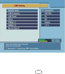
2.6.1 LNB Setting
Satellite Name
LNB Frequency
LNB Power
22 kHz
The LNB (Low Noise Block) down-converter amplifies the signal received by the antenna and lowers the frequency of the signal. The signal is then fed from the LNB to the digital receiver.
To configure the LNB setting, select the Installation > LNB Setting menu.
¤ ¡
Pressing £OK ¢button displays the satellite list, which is listed in alphabetical order. Select one of the preprogrammed satellites that corresponds to the direction of the antenna. If a desired satellite is not in the list, then select Other.
Select the local oscillator frequency of the LNB. You can input the frequency with the numeric buttons.
Set this parameter to on to supply the LNB with power.
If you have a 22 kHz tone switch box and wish to enable it, set this parameter to on. If the LNB Frequency parameter is set to Universal LNB, this parameter is not available.
2.6 Station Settings |
11 |
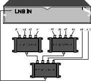
DiSEqC 1.1 and DiSEqC 1.0
This digital receiver is designed to be DiSEqC 1.1 compatible. This allows multiple antennas to be connected to one digital receiver at the same time. If you have two or more fixed antennas, then it is recommended to use a DiSEqC 1.1 switch.
If you have an only DiSEqC 1.1 switch, it is possible to connect up to 4 antennas. Set the DiSEqC 1.0 to Disable and select an item in DiSEqC1.1. If you use a DiSEqC1.1 switch and DiSEqC 1.0 switches, it is possible to connect up to 16 antennas. Connect the DiSEqC1.1 switch to the digital receiver and connect the DiSEqC 1.0 switches to the DiSEqC1.1 switch.
Set the DiSEqC 1.1 parameter and DiSEqC 1.0 parameter according to the antenna configuration. For example, to select A7 in the figure, set the DiSEqC1.1 parameter to 2 of 4 and the
DiSEqC1.0 parameter to 3 of 4.
12 |
Installation |
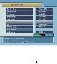
2.6.2 Service Search
To search services, select the
Installation > Service Search menu.
Satellite Name
Search Mode
Frequency
¤ ¡
Pressing £OK ¢button displays the satellite list, which is listed in alphabetical order. Select one of the preprogrammed satellites that corresponds to the direction of the antenna. If a desired satellite is not in the list, then select Other.
The Auto mode uses the information the digital receiver has. To use the Manual mode, you have to know in advance the frequency, symbol rate and polarization type of the transponder you want to search. To use the Advanced mode, you have to know the audio PID, video PID or PCR PID of the transponder you want to search. The SMATV mode is used for special purposes on the satellite master antenna TV system.
In manual, advanced or SMATV search mode, select or enter the frequency of the transponder you want to search.

2.6 Station Settings |
13 |
Symbol Rate
In manual, advanced or SMATV search mode, select or enter the symbol rate of the transponder you want to search.
Polarization
In manual or advanced search mode. select the polarization type of the transponder you want to search.
Network Search
In automatic or manual search mode, if NIT (Network Information Table) is available and this parameter is set to on, the information of the transponder you want to search will be found.
PID
PID (Packet Identifier) is a set of numbers that identifies the transport streams packets from a single data stream. In advanced search mode, enter and save the PIDs of the transponder you want to search.
FTA/Scrambled
Select the station class you want to search. FTA (Free To Air) is free, but CAS (Conditional Access System) is not.
Start Search
To start the service search,¤select¡ this menu. To cancel the search in process, press the £EXIT ¢button.
14 |
Installation |
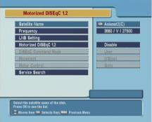
2.6.3 Motorized DiSEqC 1.2
To configure the settings with DiSEqC 1.2, select the Installation
> Motorized DiSEqC 1.2 menu.
Satellite Name
Select a satellite that will be used to identify a motor position.
Frequency
Select a transponder of which signal is strong.
Motorized DiSEqC 1.2
Set this parameter to enable if you have DiSEqC 1.2 antenna.
DiSEqC Command Mode
To finely tune the position of the antenna for better reception, select the User mode. To search the position of a satellite manullay, select the Installer mode.
Movement
In the user mode, the antenna is moved by fine tuning. In the installer mode, the antenna is moved by button (to the east) and button(to the west).
Loading...