


TOPFIELD
The User’s Manual
FREE TO AIR
Digital Satellite Receiver
TF3000Fi |
- Non-SCART model |
||
TF3000FEi |
|
|
|
|
- SCART model |
||
|
|
|
|
Please read this User s Manual carefully.
The menu structure and specification can be changed without notice.
TABLE OF CONTENTS
 INTRODUCTION


 4
4
 CONTENTS


 5
5
 FEATURES


 5
5  FRONT/ REAR PANELS
1)FRONT PANEL 


 6
6
2)REAR PANEL 


 6
6
 REMOTE CONTROL UNIT(RCU)


 9
9
 GETTING STARTED


 15
15
 FUNCTION GUIDE


 16
16  MENU OPERATIONS
1)SYSTEM SETTING 


 19
19
2)ORGANIZING CHANNEL 


 29
29
3) ORGANIZING FAVORITES |
31 |
4)INSTALLATION 


 32
32
5)INFORMATION 


 44
44
6)GAME 


 46
46
 TROUBLE SHOOTING(Q & A)


 48
48  SPECIFICATIONS


 49
49
CAUTION
RISK ELECTRIC SHOCK
Do NOT OPEN
This symbol indicates “dangerous voltage” |
This symbol indicates |
inside the product that presents a risk of |
important instructions |
electric shock or personal injury. |
accompanying the product. |
CAUTION: TO REDUCE THE RISK OF FIRE OR ELECTRIC SHOCK,
DO NOT EXPOSE THIS APPLIANCE TO RAIN OR MOISTURE
Please do not insert metal or alien substance into the slots for the Modules and Cards.
In doing so can cause damage to the STB and reduce its life span.

WARNING Warning WARNING Warning WARNING
Please read the following recommended safety precautions carefully for your safety. MAINS SUPPLY :
OVERLOADING :
LIQUIDS :
SMALL OBJECTS :
as they can fall through the ventilation slots of the IRD and
cause serious damage.
CLEANING : Disconnect the IRD from the wall socket before cleaning it. Use a dry cloth lightly dampened(no solvents) to clean
the exterior of the IRD.
VENTILATION : Do not block the decoder’s ventilation slots.
Ensure that a free airflow is maintained around the IRD. NEVER stand the IRD on soft furnishings or carpets. Do not use or store the IRD where it is exposed to direct sunlight or near a heater. NEVER stack other electronic equipment on top of the IRD.
ATTACHMENTS : Do not use any attachments that are not recommended as these may cause hazards or damage the equipment .
CONNECTION TO THE SATELLITE DISH LNB :
Disconnect the IRD from the mains before connecting or disconnecting the cable from the satellite dish. FAILURE TO DO SO CAN DAMAGE THE LNB,
SERVICING : Do not attempt to service this product yourself.
Refer all serving to qualified service agents.
LIGHTNING : It is recommended that the IRD should remain connected at all times to the mains supply and satellite dish (except when working on the LNB). However, the manufacturer’s instructions for safeguarding other equipment connected to the IRD, i, e, TV set, must be followed during lightning storms. LNB and the modem telephone line are essential.
EARTHING : The LNB cable must be earthed to the system earth for the satellite dish.
LOCATION : Locate the IRD indoor place properly to prevent lightening, raining and direct sunlight.
WARNING

INTRODUCTION
Thank you for purchasing the Digital Satellite Receiver (STB).
This Digital Satellite Receiver is fully compliant with the international DVB standard and thus transmits digital images, sounds, information guides and teletext directly to your TV through the satellite. Now you can comfortably see and receive digitally transmitted music, news, movie and sports satellite broadcasts in your office or at your home.
In the Channel Search section, both the automatic channel search method and the manual Search mode are provided. Also it supports DiSEqC 1.2, enabling you to move your antenna in order to focus your preferred satellite. You can save up to 3500 TV and 1500 Radio channels and work around with the Favorite, Lock, Delete, Move and Sort
functions. The Menu is very modern and supports different languages.
All functions can be carried out using the remote control and some of the functions can also be carried out using the front panel.
The STB is easy to use and adaptable for future advances. Please be aware that new software may change the functions of the STB.
If you have any difficulties concerning the operation of your STB, please refer to the relevant section of this manual, including the ‘Troubleshooting’. This Manual will provide you with useful information on using the STB.
INTRODUCTION
CONTENTS
Please ensure that the following items are included with the STB.
1)Remote control unit
2)Batteries (size AAA)
3)User’s Guide (this document)
FEATURES
Fully Compliant to DVB
Antenna/LNB control
-22KHz mode On/Off
-0/12V mode selection (Non-SCART model only)
-Automatic FEC Detection
-DiSEqC 1.0 & 1.2 compatible
Satellite/Channel support
- 3500 TV channels, 1500 Radio channels storable
Video/Audio
-Automatic PAL/NTSC selection
-Multi-lingual Audio support
-Automatic channel search
OSD (On Screen Display) support
-256 color support.
-Multi-lingual menu text support.
-GMT and Time Offset support
-10 favorite channel groups support
-Page Up/Page Down available on your channel list
-PIG ( Picture In Graphic ) support
Teletext
- Software emulation mode with always VBI insertion mode on.
Games are embedded.
CONTENTS / FEATURES

FRONT / REAR PANELS
1) Front Panel |
|
- LED |
|
||
|
|
|
|
|
TV / SAT |
|
||
|
|
REMOTE |
|
|
STANDBY |
|
|
|
|
|
- CHANNEL |
|
|
|
|
|
|
|
|
|
- STANDBY |
The channel buttons are to change channels. |
|
 The power button of STB (ON / Stand by)
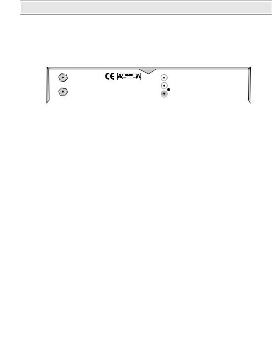
2)Rear Panel
(Non-SCART model)
FRONT/REAR PANELS
FRONT / REAR PANELS
LNB IN
 Connects the satellite antenna cable.
LNB OUT
 Use it to connect to another STB.
RS232
 Upgrades the STB Program & software
VIDEO OUTPUT
 Video output
AUDIO-RIGHT OUTPUT
 Audio output.(RED)
AUDIO-LEFT OUTPUT
 Audio output.(WHITE)
VIDEO INPUT
 Video input
AUDIO-RIGHT INPUT
 Audio input.(RED)
AUDIO-LEFT INPUT
 Audio input.(WHITE)
0/12V OUTPUT
 Chooses the LNB on the antenna.
RF OUT
 Connects the TV RF IN (ANT IN)
RF IN
 Connects the TV antenna
FRONT/REAR PANELS
FRONT / REAR PANELS
(SCART model)
FRONT/REAR PANELS
LNB IN
 Connects the satellite antenna cable.
LNB OUT
 Use it to connect to another STB.
RS232
 Upgrades the STB Program & software
TV SCART
 Connects the TV SCART
VCR SCART
 Connects the VCR SCART
VIDEO OUTPUT
 Video output
AUDIO-LEFT OUTPUT
 Audio output.(WHITE)
AUDIO-RIGHT OUTPUT
 Audio output.(RED)

REMOTE CONTROL UNIT (RCU)
 Switches the STB between Operation and Standby mode.
 Returns to the previous menu and the screen.
 Enables/ Disables the Audio.
 Selects the TV or Radio service channels and individual menu options.
 Displays the Menu on screen or returns to previous menu from submenu.
 Displays the EPG (Electronic Program Guide) on screen only when available.
CH
CH
 Tunes to the next or previous service. Services up or down through the available services.
VOL |
VOL |
 Adjusts the volume (Increase/Decrease).
CH |
VOL |
OK |
VOL |
/LIS T
CH
 Displays Channel List on screen. Selects the item in the menu mode.
 Displays the program information box on the screen and removes it.
REMOTE CONTROL UNIT
REMOTE CONTROL UNIT (RCU)
 Selects the previously viewed channel.
 Selects the TV/Radio mode.
 Changes the terrestrial TV and Satellite mode.
Selects LEFT/RIGHT/MONO/STEREO sound function.
Selects the subtitle language list for the current service.
Enables the teletext with software emulation.
 Displays the favorite channel list.
 Displays and alters the UHF setting in menu.
REMOTE CONTROL UNIT
INSTALLATION (Connection)
 First, connect both the satellite antenna and the TV line to the STB and switch the power on.
 In this manual there are some of the most common ways to connect the equipment: TV, VCR and STB.
 There are several ways of connecting the STB to the existing Audio/TV system. We recommend using one of the following setups.
 If you have problems with your connections and need help, contact your dealer or Service Provider.
1.Non-SCART model
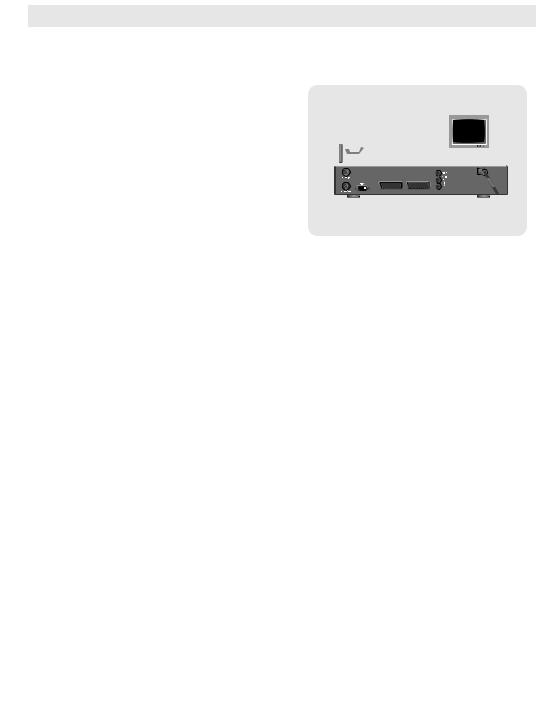
1) Connection to TV, VCR and Hi-Fi
1-1) Connection to the TV with the CINCH Cable.
Connect one end (3 connectors) of the CINCH cable to the AUDIO-RIGHT (red), AUDIO-LEFT (white) and
the VIDEO OUTPUT (yellow) socket on the STB.
Connect the other end (3 connectors) to the AUDIO-RIGHT input (red), AUDIO-LEFT input (white), and the
VIDEO input (yellow) socket on the TV or Hi-Fi.
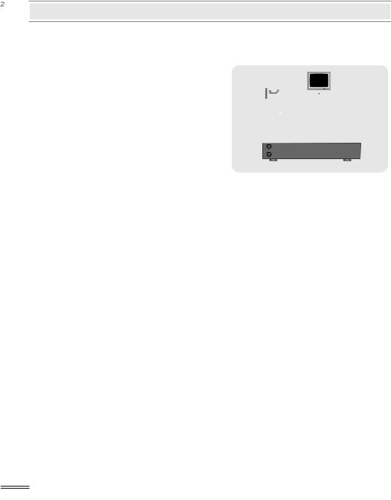
1-2) Connection to the TV using the RF cable.
Connect a terrestrial antenna to RF IN socket on the STB.
Connect one end of the RF cable to the RF OUT socket on the STB. Connect
the other end to the ANT IN socket on the TV.
INSTALLATION
INSTALLATION (Connection)
1-3) Connection to the other A/V equipment with the CINCH Cable.
Connect one end (3 connectors) of the CINCH cable to the AUDIO-RIGHT-IN (red), AUDIO- LEFT-IN (white) and the VIDEO INPUT (yellow) socket on the STB.
Connect the other end (3 connectors) to the AUDIO-RIGHT (red), AUDIO-LEFT (white) and the VIDEO OUTPUT socket
on the A/V equipment. Then STB may bypass the A/V signals of the A/V equipment in the case of stanby mode of STB.
2)Connection to the other Satellite Receiver.
Connect the satellite cable to the LNB IN socket on the STB. With a connector, connect the LNB OUT socket on the STB and the ANT IN socket of the other STB.
INSTALLATION
INSTALLATION (Connection)
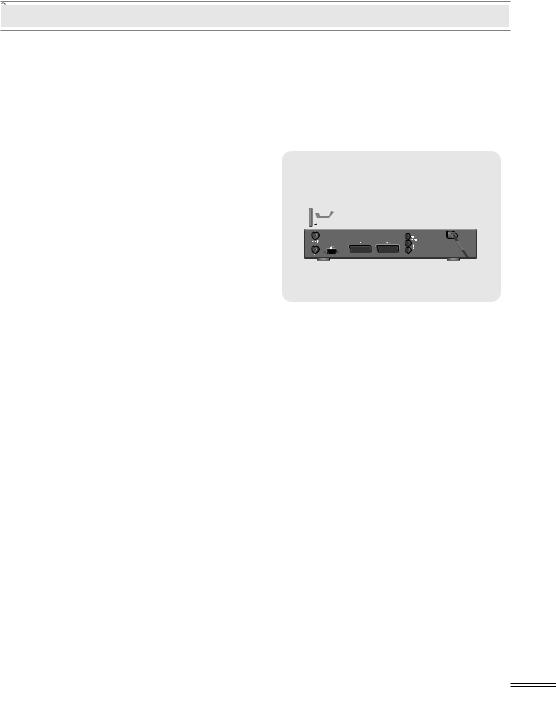
2.SCART model
1)Connection to TV, VCR and Hi-Fi
1-1) Connection to the TV with the SCART Cable.
Connect one end of the SCART cable to the TV SCART socket on the STB and the other end to a SCART socket on the TV.
1-2) Connection to the VCR with the SCART Cable.
Connect one end of the SCART cable to the VCR SCART socket on the STB and the other end to a SCART socket on the VCR.
INSTALLATION
INSTALLATION (Connection)
1-3) Connection to the TV with the CINCH Cable.
Connect one end (3 connectors) of the CINCH cable to the AUDIO-RIGHT (red), AUDIO-LEFT (white) and
the VIDEO OUTPUT (yellow) socket on the STB.
Connect the other end (3 connectors) to the AUDIO-RIGHT input (red), AUDIO-LEFT input (white) and the VIDEO input (yellow) socket on the TV or Hi-Fi.
2)Connection to the other Satellite Receiver.
Connect the satellite cable to the LNB IN socket on the STB. With a connector, connect the LNB OUT socket on the STB and the ANT IN socket of the other STB.
INSTALLATION
GETTING STARTED
Press the Power |
|
button to operate the STB from the STANDBY mode. |
|
||
|
|
||||
|
|
||||
Now, the Info box will appear for a given time and disappear. Pressing the |
|
|
button, |
||
|
|||||
the Info box will remain on the screen. The display time of the Info box is adjustable |
|||||
under the I n s t a l l a t i o n Menu of the M a i n Menu. |
|
||||
If the current broadcast has EPG (Electronic Program Guide) with it, press the |
button |
||||
to see not only the current channel’s but also other channel’s EPG without any time constraints. Also, press the  button to reserve and save the current service and to watch the broadcast automatically when it starts.
IMPORTANT: Before taking charge of your new STB, some important technical
settings are essential.
-Adjust your antenna through Dish Setting menu in installation menu.
-First, press the  button on the RCU to make the M a i n Menu appear.
- Go to the LNB Setting menu under the Channel Search item of the
Installation menu and press  button. - The Default PIN CODE is 0 0 0 0.
- Choose the right parameters for Satellite Name, LNB Frequency, 22KHz, 12 V,
DiSEqC 1.0, and Motorized System according to your LNB and satellite settings. If the right Satellite Name and LNB Frequency were not found in the list, call the dealer for satellite information.
- Then, press the |
button and go back to the Channel Search menu. |
|
- Set the Search Mode to the A u t o mode. (A Manual or Advanced Search |
||
can always be performed later on) |
|
|
- Select the Start Search... item and press |
button. |
|
- The search procedure will take a while. Press the |
button when the searching |
|
process is over (100%) to confirm and save the new channel list. |
||
|
|
STARTEDNGGETTI |
- For further information, please refer to the LNB Setting item of the MENU OPERATIONS on this manual.
 Loading...