


TF 4000
Table of contents
 Loading...
TOPFIELD
TF 4000 PVR Plus
User Guide
Digital Satellite Receiver
Personal Video Recorder


Contents iii
Contents
1 Introduction 1
1.1 Features . . . . . . . . . . . . . . . . . . . . . . . . . . . . . . . 1
1.2 Controlling the digital receiver . . . . . . . . . . . . . . . . . . 2
1.2.1 The front panel . . . . . . . . . . . . . . . . . . . . . . . 3
1.2.2 The remote control . . . . . . . . . . . . . . . . . . . . . 4
1.3 What is common interface? . . . . . . . . . . . . . . . . . . . . 6
2 Setup 8
2.1 Unpacking . . . . . . . . . . . . . . . . . . . . . . . . . . . . . . 8
2.2 Safety precautions . . . . . . . . . . . . . . . . . . . . . . . . . 8
2.3 Rear panel connections . . . . . . . . . . . . . . . . . . . . . . . 10
2.4 Connecting up your digital receiver . . . . . . . . . . . . . . . 11
2.4.1 Connecting the antenna . . . . . . . . . . . . . . . . . . 12
2.4.2 Connecting to your television . . . . . . . . . . . . . . 13
2.4.3 Connecting to your video cassette recorder . . . . . . . 14
2.5 Switching on for the first time . . . . . . . . . . . . . . . . . . . 15
2.5.1 Inserting batteries in the remote control . . . . . . . . . 15
2.5.2 Powering on and checking picture . . . . . . . . . . . . 15

iv Contents
3 Preference Settings 17
3.1 Language settings . . . . . . . . . . . . . . . . . . . . . . . . . . 17
3.2 Video and audio settings . . . . . . . . . . . . . . . . . . . . . . 19
3.2.1 Television standard . . . . . . . . . . . . . . . . . . . . 19
3.2.2 Colour model . . . . . . . . . . . . . . . . . . . . . . . . 19
3.2.3 Video cassette recorder . . . . . . . . . . . . . . . . . . 20
3.2.4 Television aspect ratio . . . . . . . . . . . . . . . . . . . 20
3.2.5 Sound mode . . . . . . . . . . . . . . . . . . . . . . . . 21
3.3 Local time setting . . . . . . . . . . . . . . . . . . . . . . . . . . 21
3.4 Parental control . . . . . . . . . . . . . . . . . . . . . . . . . . . 24
3.5 Adjusting the on-screen display . . . . . . . . . . . . . . . . . . 25
3.6 To turn on the time shift feature . . . . . . . . . . . . . . . . . . 25
4 Service Search 26
4.1 Searching broadcasting services . . . . . . . . . . . . . . . . . . 26
4.1.1 Configuring LNB settings . . . . . . . . . . . . . . . . . 26
4.1.2 Configuring DiSEqC 1.2 settings . . . . . . . . . . . . . 29
4.1.3 Configuring USALS settings . . . . . . . . . . . . . . . 30
4.1.4 Searching services . . . . . . . . . . . . . . . . . . . . . 32
4.2 Copying services . . . . . . . . . . . . . . . . . . . . . . . . . . 35
4.3 Resetting to factory settings . . . . . . . . . . . . . . . . . . . . 35
5 Daily Usage 36
5.1 Volume control . . . . . . . . . . . . . . . . . . . . . . . . . . . 36
5.2 Watching television . . . . . . . . . . . . . . . . . . . . . . . . . 36
5.2.1 The services list . . . . . . . . . . . . . . . . . . . . . . . 36
5.2.2 The favourite services list . . . . . . . . . . . . . . . . . 39
5.2.3 Viewing programme information . . . . . . . . . . . . 40
5.2.4 Selecting audio tracks . . . . . . . . . . . . . . . . . . . 41
5.2.5 Selecting subtitle tracks . . . . . . . . . . . . . . . . . . 41

Contents v
5.2.6 Viewing teletext . . . . . . . . . . . . . . . . . . . . . . 41
5.3 Viewing electronic programme guide . . . . . . . . . . . . . . 41
5.4 Watching multifeed programme . . . . . . . . . . . . . . . . . 42
5.5 Using time shift . . . . . . . . . . . . . . . . . . . . . . . . . . . 43
5.6 Using picture in picture . . . . . . . . . . . . . . . . . . . . . . 44
6 Listing Services 46
6.1 Editing the services list . . . . . . . . . . . . . . . . . . . . . . . 46
6.2 Editing the favourite list . . . . . . . . . . . . . . . . . . . . . . 48
6.3 How to use on-screen keyboard . . . . . . . . . . . . . . . . . . 50
6.4 Transferring receiver data . . . . . . . . . . . . . . . . . . . . . 50
6.5 Editing channel data on your computer . . . . . . . . . . . . . 51
6.5.1 Editing satellite and transponder list . . . . . . . . . . 52
6.5.2 Editing television and radio services list . . . . . . . . 55
6.5.3 Editing favourite list . . . . . . . . . . . . . . . . . . . . 56
7 Recording and Playing 58
7.1 Recording a programme . . . . . . . . . . . . . . . . . . . . . . 59
7.1.1 Instant recording . . . . . . . . . . . . . . . . . . . . . . 59
7.1.2 Current programme recording . . . . . . . . . . . . . . 62
7.1.3 Timer recording . . . . . . . . . . . . . . . . . . . . . . 64
7.1.4 Scheduling a recording using the programme guide . 67
7.1.5 Recording a time-shifted programme . . . . . . . . . . 68
7.1.6 Recording a pay service programme . . . . . . . . . . . 69
7.2 File archive . . . . . . . . . . . . . . . . . . . . . . . . . . . . . 69
7.2.1 To delete a recording . . . . . . . . . . . . . . . . . . . . 70
7.2.2 To sort recordings . . . . . . . . . . . . . . . . . . . . . 71
7.2.3 To lock a recording . . . . . . . . . . . . . . . . . . . . . 72
7.2.4 To rename a recording . . . . . . . . . . . . . . . . . . . 73
7.2.5 To make a new folder . . . . . . . . . . . . . . . . . . . 74

vi Contents
7.2.6 To move a recording to another folder . . . . . . . . . . 75
7.3 Playing back a recording . . . . . . . . . . . . . . . . . . . . . . 75
7.3.1 To navigate using the progress bar . . . . . . . . . . . . 76
7.3.2 To play in slow motion . . . . . . . . . . . . . . . . . . 77
7.3.3 To play in fast motion . . . . . . . . . . . . . . . . . . . 78
7.3.4 To make a bookmark . . . . . . . . . . . . . . . . . . . . 79
7.3.5 To play back a recording repeatedly . . . . . . . . . . . 80
7.3.6 To play back recordings in sequence . . . . . . . . . . . 81
7.3.7 To play back a scrambled recording . . . . . . . . . . . 82
7.4 Editing a recording . . . . . . . . . . . . . . . . . . . . . . . . . 82
7.5 Copying a recording . . . . . . . . . . . . . . . . . . . . . . . . 83
7.6 Formatting the hard disk . . . . . . . . . . . . . . . . . . . . . . 83
8 Firmware Update 84
8.1 Checking the firmware information . . . . . . . . . . . . . . . 84
8.2 From your computer via RS-232 port . . . . . . . . . . . . . . . 86
8.3 From another digital receiver via RS-232 port . . . . . . . . . . 87
8.4 Over the air . . . . . . . . . . . . . . . . . . . . . . . . . . . . . 88
Index 89

1
Chapter 1
Introduction
The TF 4000 PVR Plus digital receiver is fully compliant with
the international Digital Video Broadcasting (DVB) standard,
and can receive digital broadcasts. For its operation you need
an antenna, which must be installed appropriately.
NOTE
In general we equate a channel with a frequency. Unlike ana-
logue broadcasts, however, digital broadcasts are not all as-
signed to their own frequencies; instead, multiple television
broadcasts are transmitted through a single frequency. The fre-
quency in digital broadcasting is usually called transponder. To
reduce confusion in this manual, the word
service
is preferably
used than
channel
as a term to indicate one television or radio
broadcast.
1.1 Features
The TF 4000 PVR Plus digital receiver has the following fea-
tures:
•
Supports DiSEqC 1.0, DiSEqC 1.1, DiSEqC 1.2 and US-
ALS.

2 Introduction
• Can store up to 5000 television and radio services.
• You can edit the services list.
• You can create favourite lists of your favourite services.
•
You can view information about the current television or
radio programme.
•
Has an electronic programme guide that provides an
overview of scheduled programmes.
•
You can update the firmware of the digital receiver to the
latest version, provided by the manufacturer.
•
You can record one broadcasting service while you are
currently watching another.
•
The large storage capacity of the built-in hard disk drive
allows you to record up to about 60 hours of television
—in case of 250 gigabytes—in excellent picture and sound
quality.
•
Time shift is a special technical feature available on the
TF 4000 PVR Plus. You can pause the programme you
are watching and resume it again at a later time. Then
you can quickly go to whatever part of the current pro-
gramme by fast foward and rewind search.
1.2 Controlling the digital receiver
The digital receiver can be operated with the remote control
and the buttons on the front panel.
NOTE
When the digital receiver is off but plugged into a wall outlet,
we say that it is in standby mode; on the other hand, when it is
on, it is in operation mode. Even when you are not using the
digital receiver, you should keep it plugged into a wall outlet
to be in standby mode so that it can run timer events at any
time.
1.2 Controlling the digital receiver 3
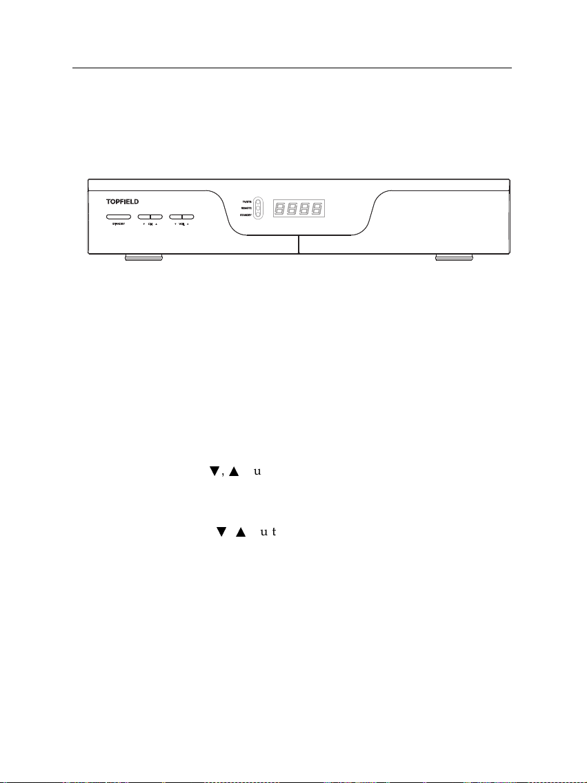
1.2.1 The front panel
The front panel of the digital receiver has buttons to control the
digital receiver, and specific lamps and a display to indicate its
status. The following indicates what they mean.
STANDBY
lamp lights up while the digital receiver is in
standby mode.
TV/STB
lamp lights up while your video recorder operates
instead of the digital receiver. See
§
3.2.3 for more
details.
REMOTE
lamp lights up whenever you press a button on
the remote control.
STANDBY
button switches the digital receiver between
standby mode and operation mode.
CH
c
,
a
buttons switch to previous or next service. They
are also used to navigate in menus and interactive
screens.
VOL
c
,
a
buttons decrease or increase the volume. They
are also used to change values for menu options.
Front display
displays the current time in standby mode,
and displays the current service in operation mode.
Pull the right edge of the front panel to open the flap. You have
to insert your subscription card into the front slot to watch pay
services.
4 Introduction
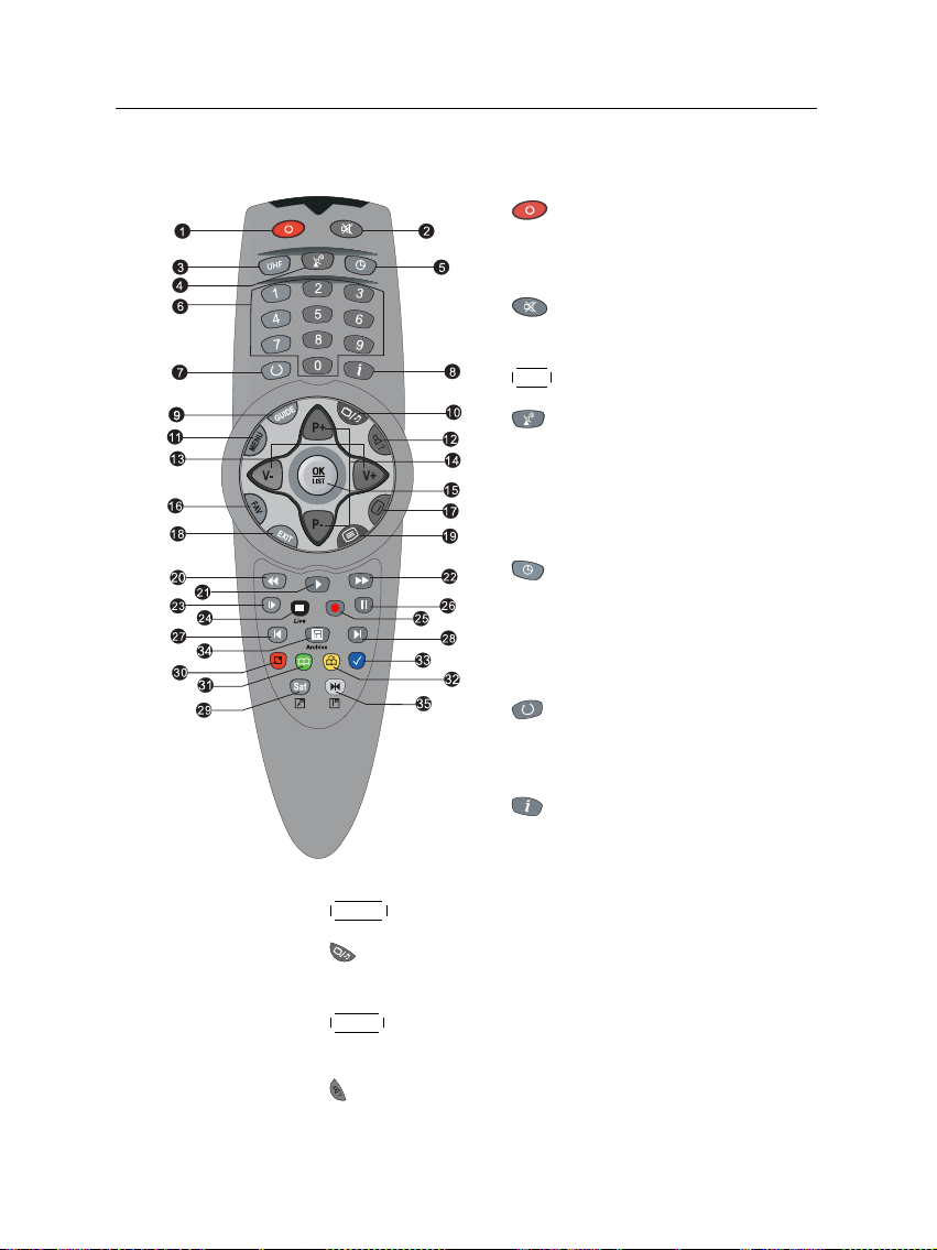
1.2.2 The remote control
1
button switches the digital re-
ceiver between standby mode and
operation mode.
2
mutes the sound. Press again to
switch it back on.
3
UHF is not used in this model.
4
switches the output of the TV
SCART socket between the digital
receiver and the device connected to
the VCR SCART socket. See
§
3.2.3
for more details.
5
is used to set a sleep timer.
6
Numeric buttons are used to enter a
service number for service change or
to specify values for menu options.
7
switches between the current
service and the previously viewed
one.
8
displays the service information
box. It is also used to display more
information about a programme.
9
GUIDE displays the electronic programme guide.
10
switches between television services and radio ser-
vices.
11
MENU
displays the main menu. It is also used to return
to the previous menu from a submenu.
12
is used to select an audio track and a sound mode, or
a video track of multifeed programme.

1.2 Controlling the digital receiver 5
13
V−
,
V+
buttons decrease or increase the volume. They
are also used to change values for menu options.
14
P−
,
P+
buttons switch to previous or next service.
They are also used to navigate in menus and interactive
screens.
15
OK
displays the services list. See
§
5.2.1 for more details.
It is also used to select a menu item.
16
FAV displays the favourite lists.
17
is used to select a subtitle track.
18
EXIT is used to exit the current screen.
19
displays teletext.
20
is used to start reverse playback. Subsequent presses
increase the rewind speed.
21
resumes normal playback speed, or displayes the
progress bar for navigation on playback or time shift. To
play a recorded programme, see button 34.
22
is used to start fast motion playback. Subsequent
presses increase the playback speed.
23
is used to start slow motion playback. Subsequent
presses change the playback speed.
24
is used to stop playback, to stop recording, or to jump
back to live television from time-shifted television.
25
is used to start recording.
26
pauses live television or playback of a recorded pro-
gramme.
27
changes the position of sub-screen counterclockwise.
It is also used to jump back to beginnng of recording
during a playback.
6 Introduction
28
changes the position of sub-screen clockwise. It is also
used to jump to end of recording during a playback.
29
SAT
displays the satellite list with their services list. It is
also used to swap the sub-picture with the main picture.
See § 5.6 for more details.
30
is used to display, minify or hide the sub-screen. See
§ 5.6 for information about picture-in-picture.
31
is used to make a bookmark during playback or time
shift.
32
is used to jump to next bookmark position or to jump
forward by 30 seconds.
33
is used to jump back 10 seconds for an instant replay.
It is also used to edit a recording.
34
is used to display the list of recorded programmes
that are stored on the internal hard disk drive. See
§
7.2
for more details.
35
displays the services list for sub-screen. It is also used
to specify a block for editing or for repeated playback.
The , , , and buttons have additional different
functions per menu besides their own function. They will be
guided by on-screen help.
1.3 What is common interface?
Some broadcasts are scrambled so that only paid
subscribers can enjoy them. Scrambled services
can only be viewed with a Conditional Access
Module (CAM) and a subscription card belong-
ing with the scrambling system.
Common Interface (CI) is the slot on a digitial
receiver into which a conditional access module
may be insterted. The front of the digital receiver
has two common interfaces.
1.3 What is common interface? 7
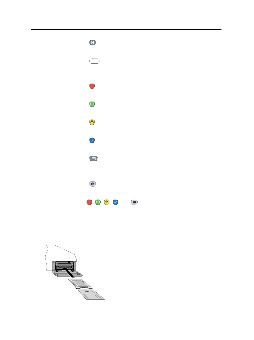
To watch a pay service, you should take the following steps:
1.
Purchase a conditional access module and a subscription
card for the pay service you want to watch.
2.
Insert the subscription card into the conditional access
module.
3.
Insert the conditional access module into a common in-
terface on the front of the digital receiver.
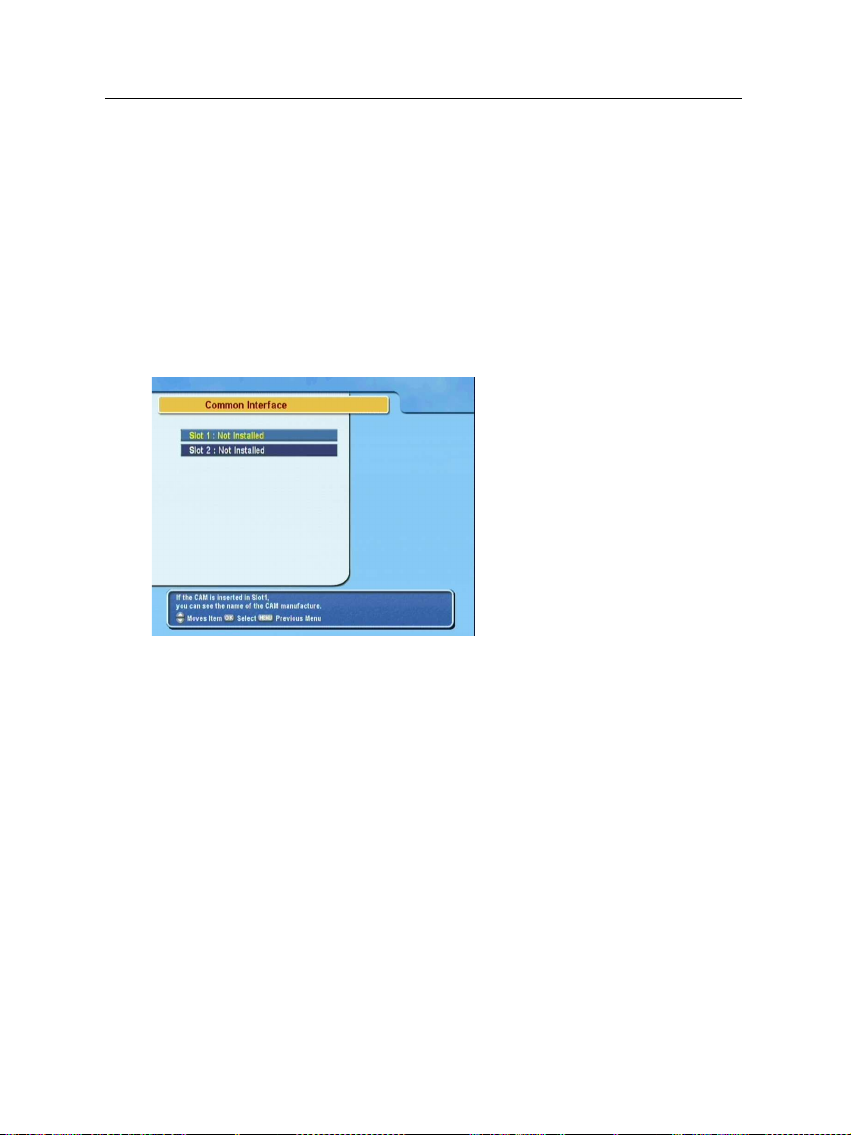
To view the information about
the module and subscription
card inserted into the digital re-
ceiver, select the Common Inter-
face menu. You should see a
screen like the left figure.

8 Setup
Chapter 2
Setup
2.1 Unpacking
Before going any further, check that you have received the
following items with your digital receiver.
• Remote control unit
• Two batteries for the remote control (AAA 1.5 V)
• User manual
NOTE
Accessories may vary according to your local area.
2.2 Safety precautions
Please read carefully the following safety precautions.
•
The mains power must be 90 to 250 volt. Check it before
connecting the digital receiver to the wall outlet. For
the power consumption of the digital receiver, refer to
Table 2.1.

2.2 Safety precautions 9
•
The wall outlet should be near the equipment. Do not
run an extension lead to the unit.
•
Do not expose the digital receiver to any moisture. The
digital receiver is designed for use indoors only. Use dry
cloth when cleaning the digital receiver.
• Place the digital receiver on a firm and level surface.
•
Do not place the digital receiver close to heat emitting
units or in direct sunlight, as this will impair cooling.
Do not lay any objects such as magazines on the digi-
tal receiver. When placed in a cabinet, make sure there
is a minimum space of 10 centimetres around it. For
the physical specification of the digital receiver, refer to
Table 2.2.
•
Protect the power cord from being walked on or pinched.
If the wires are exposed or the cord is damaged, do not
use the digital receiver and get the cord replaced.
•
Never open the digital receiver casing under any circum-
stances. The warranty will be void.
• Refer all servicing to a qualified service technician.
Table 2.1: Power specifications
Input voltage 90 to 250 V AC, 50/60 Hz
Power consumption 55 W at maximum in operation
10 W in standby
Table 2.2: Physical specifications
Size 340× 60× 265 mm
Weight 3.4 kg
Operating temperature 0 to 45 °C
Storage relative humidity 5 to 95 %
10 Setup
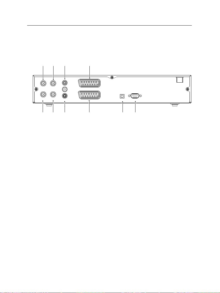
2.3 Rear panel connections
The TF 4000 PVR Plus has a wide range of connections on the
back panel.
RS-232S/PDIFVCR
TV
IF 2 OUT
LNB 2 IN
IF 1 OUT
LNB 1 IN
VIDEO
AUDIO
R
L
1
2
3
4
5
6
7
8 9 10
Check what connections your television set has in comparison
with the digital receiver.
1
LNB 1 IN
Satellite broadcasting signal input socket for
the first tuner.
2
IF 1 OUT
Satellite broadcasting signal output socket
through the first tuner.
3
LNB 2 IN
Satellite broadcasting signal input socket for
the second tuner.
4
IF 2 OUT
Satellite broadcasting signal output socket
through the second tuner.
5
VIDEO
Composite video output socket for the televi-
sion set. (yellow)
6
AUDIO L/R
Stereo audio output socket for the television
set or the audio system. (white/red)
7
TV
Audio and video output socket for the televi-
sion set.
8
VCR
Audio and video input/output socket for the
video cassette recorder or suchlike.

2.4 Connecting up your digital receiver 11
9
S/PDIF
Dolby digital output socket for the audio sys-
tem.
10
RS-232
Serial port for firmware update and data
transfer.
Table 2.3: Connectors specifications
VIDEO Composite video (CVBS) output
AUDIO Left & right audio output
TV CVBS/S-Video/RGB/YUV video output
Left & right audio output
VCR CVBS video output
Left & right audio output
CVBS/S-Video/RGB video input for bypass
Left & right audio input for bypass
S/PDIF Dolby digital audio output
RS-232 115.2 kbps at maximum
2.4 Connecting up your digital receiver
There are several ways to set up the digital receiver. Set up the
digital receiver suitably to your television and other appliances.
If you have any problem with your setup or need help, contact
your dealer.
12 Setup
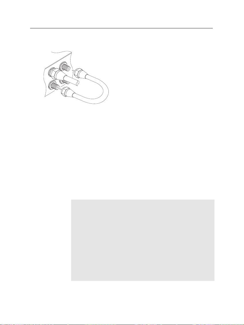
2.4.1 Connecting the antenna
Whatever sort of connection you have be-
tween the digital receiver and the television,
you need to connect the digital receiver to
your television antenna so that it can receive
digital television services.
Connect the antenna cable to the LNB 1 IN
connector on the back panel of the digital
receiver.
Also, you must ensure that there is a con-
nection to both the LNB 1 IN and LNB 2 IN
connectors on your digital receiver, so that
both tuners work properly.
Normally you do that by using a loop cable to link from the IF
1 OUT connector to the LNB 2 IN connector.
If you have two antennas without DiSEqC switch, then you
have to connect a cable from the other antenna directly to
the LNB 2 IN connector rather than using the loop cable. If
you have another digital receiver, link it from the IF 2 OUT
connector.
NOTE
The digital receiver can supply a current of 500 milliampere at
maximum for antenna devices including LNB, DiSEqc switch
and antenna rotor through each antenna input connection sepa-
rately but not simultaneously. So if there are too many antenna
devices to be supplied with power through antenna input con-
nections simultaneously for a long time, your LNBs may lack
power to operate. So it is recommended to link the IF 1 OUT
connector to the LNB 2 IN connector with a loop cable even
though the digital receiver is designed to operate over two
antennas alternatively.
2.4 Connecting up your digital receiver 13
2.4.2 Connecting to your television
Between all the following connectors of the digital receiver, we
recommend you to use the first connector to get best picture
quality. If your television does not have the matching connector,
then use the next connector in the following order for better
picture quality.
1. SCART connector (TV)
2. Composite connector (VIDEO)
You should configure audio and video settings after connecting
up the digital receiver. See § 3.2 for detailed description.
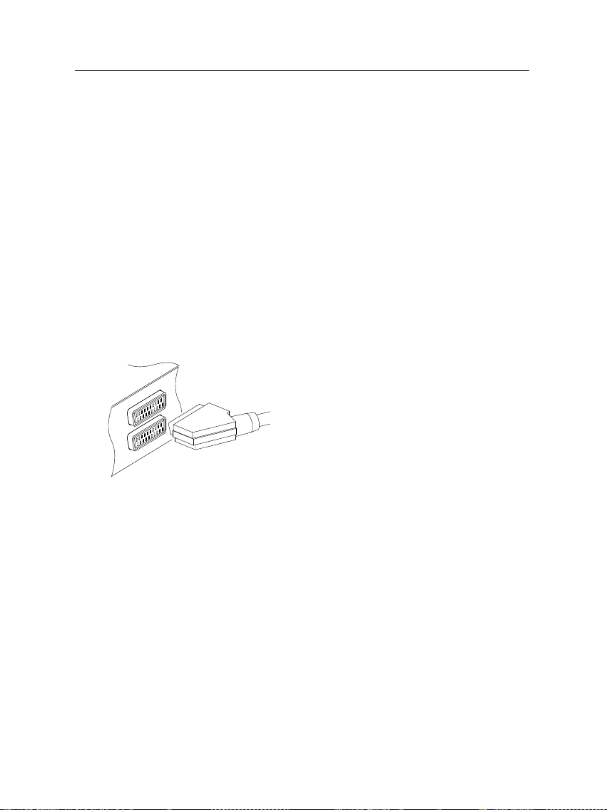
To use the SCART connector
For best results with a standard television set,
you should use a SCART cable, plugging one
end into the TV socket on the digital receiver
and the other end into a free SCART socket
on your television.
Some televisions have inputs via Component
connector or S-Video connector rather than
SCART.
If you have such a television, use an appropriate conversion ca-
ble to link the TV socket on the digital receiver to the matching
socket on your television.
If you connect with a standard SCART cable, you do not have
to make audio connections because the SCART connector can
output stereo audio. But if you use a conversion cable, such as
SCART-to-Component, you have to make audio connections.
14 Setup
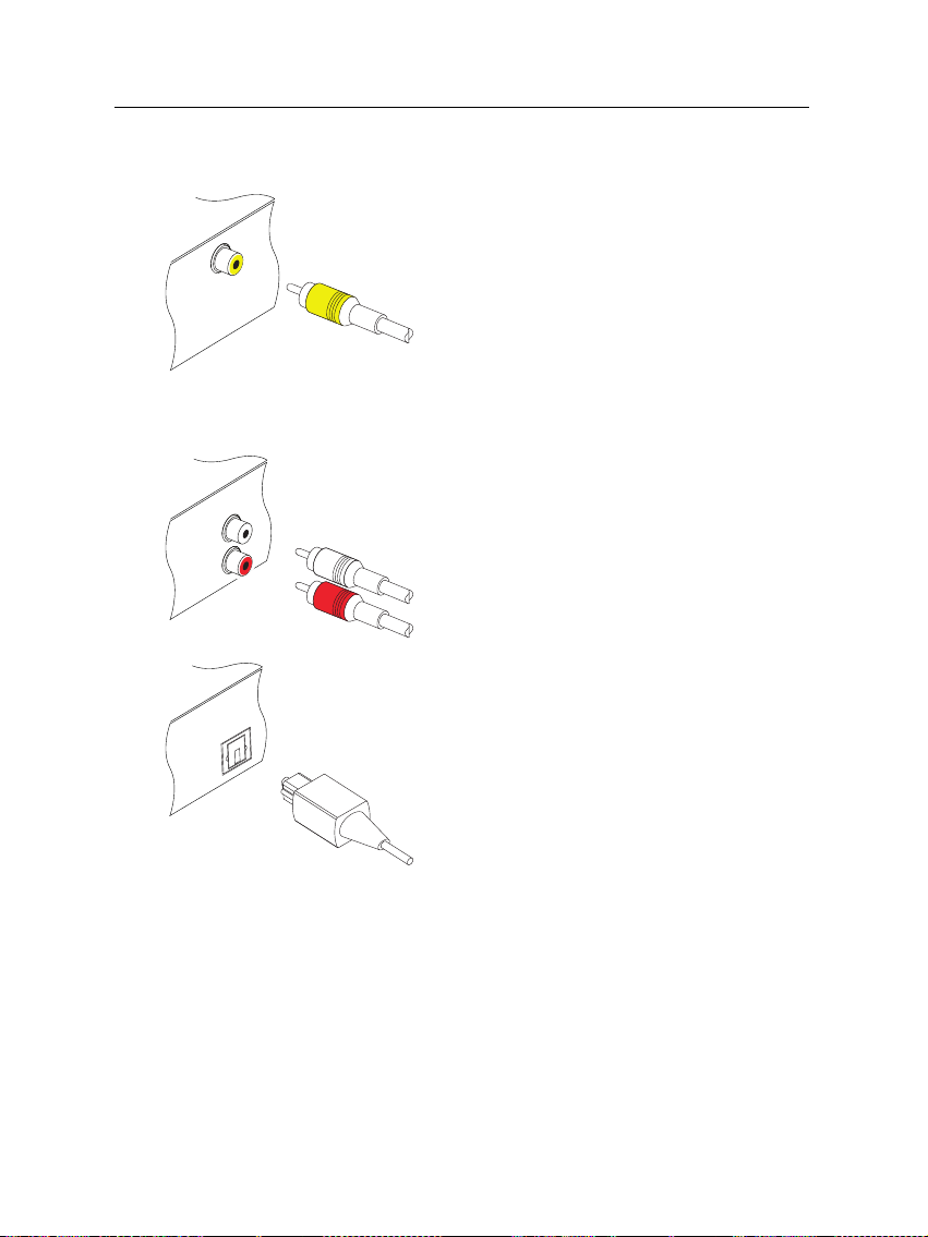
To use the composite video connector
You will need to obtain a composite video
cable (RCA cable) to use the composite video
connector. Plug one end of the cable into the
VIDEO (yellow) socket on the digital receiver,
and the other end into the matching socket
on your television.
To connect the audio connectors
You will need to obtain an audio cable (RCA
cable) to connect the audio connectors. Plug
one end of the cable into the AUDIO L (white)
and AUDIO R (red) sockets on the digital re-
ceiver, and the other end into the matching
sockets on your television or audio system.
To enjoy Dolby digital audio, your televi-
sion or audio system must be able to decode
Dolby digital audio, and you will need to ob-
tain a S/PDIF cable. Plug one end of the
cable into the S/PIDF socket on the digital
receiver, and the other end into the matching
socket on your audio system.
2.4.3 Connecting to your video cassette recorder
The digital receiver can also output video to another appliance
such as a video cassette recorder or video receiver through an
auxiliary SCART connector.

2.5 Switching on for the first time 15
You will need to obtain a SCART cable to use
the auxiliary SCART connector. Plug one end
of the cable into the VCR socket on the digital
receiver, and the other end into the match-
ing socket on your video cassette recorder or
suchlike.
2.5 Switching on for the first time
Now that you have your digital receiver connected, you should
plug it in to a mains socket. Ensure that your television set is
turned on, so that you will be able to see the display from the
digital receiver.
2.5.1 Inserting batteries in the remote control
To insert the batteries, open the battery compartment by remov-
ing the lid, and then insert the batteries observing the polarity,
which is marked on the base of the battery compartment.
If the digital receiver no longer reacts properly to remote con-
trol commands, the batteries may be flat. Be sure to remove
used batteries. The manufacturer accepts no liability for the
damage resulting from leaking batteries.
NOTE
Batteries, including those which contain no heavy metals, may
not be disposed of with household waste. Please dispose of
used batteries in an environmentally sound manner. Find out
about the legal regulations which apply in your area.
2.5.2 Powering on and checking picture
Now, press the button in top left corner on the remote
control.
If the picture is good, you can skip to
§
4.1.4 to search for the
available television and radio services. Otherwise, you may

16 Setup
need to temporarily connect the composite video connector
(VIDEO) to your television set so that you can see the on-screen
menus in order to configure the video settings.
17
Chapter 3
Preference Settings
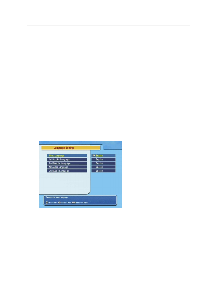
3.1 Language settings
You can select the language in
which the menu would be dis-
played. In addition to that, you
can select which language of au-
dio track and of subtitle track
should be output.
Select the System Setting
>
Lan-
guage Setting menu. You should
see a screen like the left figure.
Menu language
The digital receiver supports many menu languages: Dutch,
English, German, French, Italian, Russian, Turkish and so forth.
Set the Menu Language option to your desired language. Once
you select a language, the menu will be immediately displayed
in the selected language.

18 Preference Settings
Subtitle language
Set the 1st Subtitle Language option and the 2nd Subtitle Lan-
guage option to your desired languages. When you watch a
programme, if the programme has a subtitle track of the lan-
guage that is designated for the 1st Subtitle Language, it will be
displayed. If the first language is not available but the second
language is available, the subtitle of the second language will
be displayed. If there is not any available language, no subtitle
will be displayed.
Apart from this setting, you can select a subtitle track with the
button. See § 5.2.5 for detailed description.
Audio language
Set the 1st Audio Language option and the 2nd Audio Lan-
guage option to your desired languages. When you watch a
programme, if the programme has an audio track of the lan-
guage that is designated for the 1st Audio Language, it will
be output. If the first language is not available but the second
language is available, the audio of the second language will be
output.
Apart from this setting, you can select an audio track with the
button. See § 5.2.4 for detailed description.
3.2 Video and audio settings 19
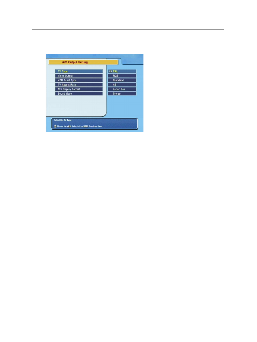
3.2 Video and audio settings
You have to configure the video
and audio settings appropriately
to your television set and other
appliances.
Select the System Setting
>
A/V Output Setting menu. You
should see a screen like the left
figure.
3.2.1 Television standard
The digital receiver supports two television standards. One
is PAL standard, and the other is NTSC standard. PAL was
adopted in European countries while NTSC is adopted in USA,
Canada, Mexico and so forth.
If you have a PAL television, you have to set the TV Type
option to PAL. In that case, if you switch to a service of the
NTSC standard, the digital receiver will presents the pictures
converting into the PAL standard. However, it is inevitable to
lose a little picture quality. Likewise, the contrary case brings
about the same result.
The best thing is to watch PAL services with a PAL television
and to watch NTSC services with a NTSC television. However,
a multi television set is able to process both of them. So if
you have a multi television set, you had better set the TV Type
option to Multi. Then the digital receiver will present pictures
without standard conversion.
3.2.2 Colour model
Through the TV SCART connector, the digital receiver is able
to output video in various colour models. If you have the

20 Preference Settings
digital receiver linked to your television via this connector,
you should set the Video Output option to your desired colour
model. If you have connected via the RCA connector labeled
VIDEO on the back panel, you do not have to set this option
because the digital receiver outputs CVBS video through the
RCA connector independent of the SCART connector.
It is known in general that the RGB colour model provides the
best video quality with little difference from the YUV colour
model but the CVBS colour model does the least. So RGB
would be most desirable for this option.
3.2.3 Video cassette recorder
You can have the digital receiver linked to your video cassette
recorder or such an appliance via the VCR SCART connector. In
that case, the digital receiver will operate differently depending
on the setting of the VCR Scart Type option. If the option is
set to Standard, the digital receiver will pass the video from
the video cassette recorder to your television when it starts
playback. But if the option is set to External A/V, the digital
receiver will not pass the video automatically. To pass it, you
have to press the button.
NOTE
It is impossible for the digital receiver to record the video that
the video recorder plays back because the digital receiver is
just a bypass for the video recorder.
3.2.4 Television aspect ratio
If you have a wide-screen television, set the TV Aspect Ratio
option to 16:9.
Otherwise, if you have a normal-screen television, set the TV
Aspect Ratio option to 4:3.

3.3 Local time setting 21
You cannot fully enjoy wide-screen programmes with your
normal-screen television as the above figures show. The left
figure shows a normal picture displayed in the normal screen.
To watch wide-screen programmes in the shape like the centre
figure, set the 16:9 Display Format option to Letter Box. Wide-
screen pictures then will be reduced to fit to the width of the
normal screen. Otherwise, to watch them in the shape like the
right figure, set it to Center extract. Wide-screen pictures then
will be cut out on the left and right sides equally to fit to the
width of the normal screen.
3.2.5 Sound mode
Basically, there are two audio sources as you can find two audio
sockets on the back panel of the digital receiver. You can enjoy
only one source or both of them in either stereo or mono. Set
the Sound Mode option as you desire.
Apart from this setting, you can change the sound mode with
the button. See § 5.2.4 for detailed description.
3.3 Local time setting
You should set your local time for timer events. If you do not
set the local time right, the programme time table provided by
the programme guide may be distrustful. For the programme
guide, refer to § 5.3.
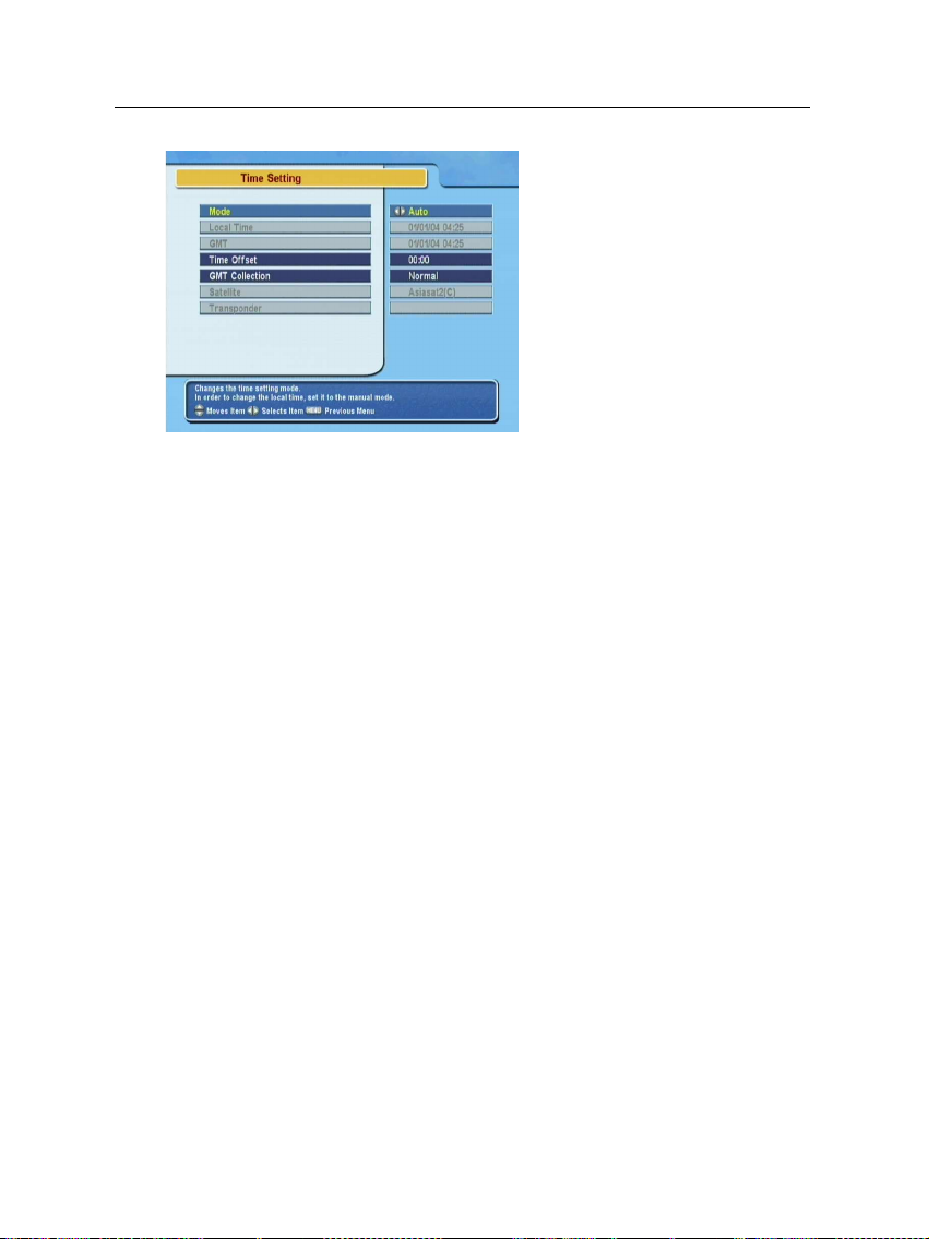
22 Preference Settings
Select the System Setting
>
Time
Setting menu. You should see a
screen like the left figure.
You can set the clock manually
or use the time signal, Green-
wich Mean Time (GMT), carried
as part of the digital television
broadcast.
To use Greenwich Mean Time,
take the following steps:
1.
Set the Mode option to Auto; then the Time Offset option
becomes enabled.
2.
Set the Time Offset option to the time difference between
your time zone and GMT referring to Table 3.1.
3.
To get Greenwich mean time, set the GMT Collection
option to one among the following:
Normal from all transponders
CAS TP from transponders of pay services
User Select from transponders specified by you
If you set it to User Select, then the Satellite option and
the Transponder option become enabled. Select your de-
sired satellite and transponders at those options. With
the above settings, the digital receiver will scan all trans-
ponders specified one by one until to get the Greenwich
Mean Time.
4.
Make sure that your local time is correctly displayed on
the Local Time option.
To set the local time yourself, set the Mode option to Manual and
enter your local time to the Local Time option with the numeric
buttons. The time format is day/month/year 24-hour:minute.

3.3 Local time setting 23
Table 3.1: Time offset table
Time offset City
GMT − 12:00 Eniwetok, Kwajalein
GMT − 11:00 Midway Island, Samoa
GMT − 10:00 Hawaii
GMT − 09:00 Alaska
GMT − 08:00 Pacific Time US, Canada
GMT − 07:00 Mountain Time US, Canada
GMT − 06:00 Central Time US, Canada, Mexico City
GMT − 05:00 Eastern Time US, Canada, Bogota, Lima
GMT − 04:00 Atlantic Time Canada, La Paz
GMT − 03:30 Newfoundland
GMT − 03:00 Brazil, Georgetown, Buenos Aries
GMT − 02:00 Mid-Atlantic
GMT − 01:00 Azores, Cape Verde Islands
GMT London, Lisbon, Casablanca
GMT + 1:00 Paris, Brussels, Copenhagen, Madrid
GMT + 2:00 South Africa, Kaliningrad
GMT + 3:00 Baghdad, Riyadh, Moscow, St. Petersburg
GMT + 3:30 Tehran
GMT + 4:00 Abu Dhabi, Muscat, Baku, Tbilisi
GMT + 4:30 Kabul
GMT + 5:00 Ekaterinburg, Islamabad, Karachi, Tashkent
GMT + 5:30 Bombay, Calcutta, Madras, New Delhi
GMT + 6:00 Almaty, Dhaka, Colombo
GMT + 7:00 Bangkok, Hanoi, Jakarta
GMT + 8:00 Beijing, Perth, Singapore, Hong Kong
GMT + 9:00 Tokyo, Seoul, Osaka, Sapporo, Yakutsk
GMT + 9:30 Adelaide, Darwin
GMT + 10:00 Eastern Australia, Guam, Vladivostok
GMT + 11:00 Magadan, Solomon Islands, New Caledonia
GMT + 12:00 Fiji, Auckland, Wellington, Kamchatka
If daylight saving time is observed in your state at the moment,
set the Daylight Saving Time option to On.
NOTE
Daylight saving time adds one hour to the time when the op-
tion is set to On. When setting the time offset from Greenwich
Mean Time, make sure that time offset does not include day-
light saving time.
24 Preference Settings
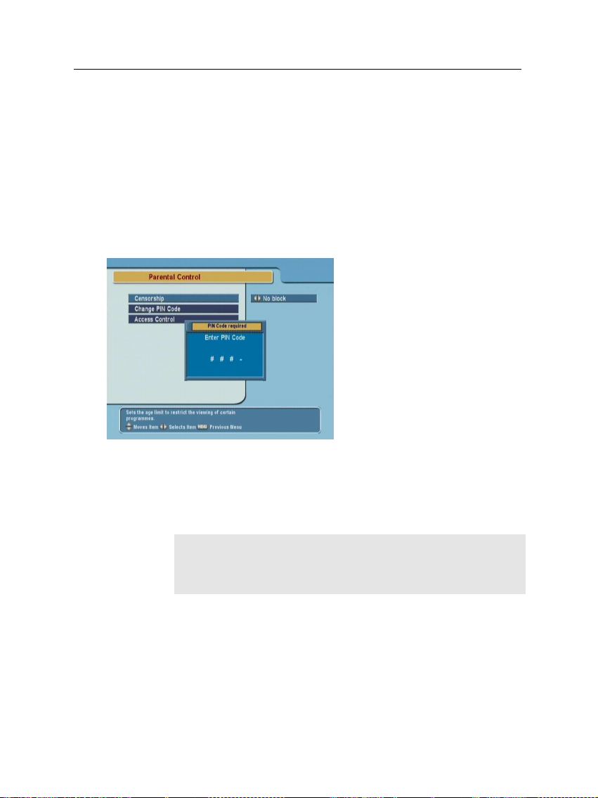
3.4 Parental control
In general, television programmes are classified according to
the level of violence, nudity and language of their content.
When you are watching a programme, you can check its pro-
gramme classification on the information box. For the informa-
tion box, see § 5.2.3.
You can prevent your children from watching specific pro-
grammes by specifying a programme classification.
Select the System Setting
>
Parental Control menu. You
should see a screen like the
left figure, and you will be
asked your Personal Identifica-
tion Number (PIN). The number
is initially set to ‘0000’.
If you wish to block 15 or above rated programmes, set the
Censorship option to 15 (age). Setting it to No block blocks no
programme; on the other hand, setting it to Total block blocks
every programme.
NOTE
If a programme does not have any programme classification
information, your censorship setting will not take effect.
If anyone is trying to watch a programme that is of or above
the censorship setting, the person has to enter the personal
identification number to override.
To change the number, select the Change PIN Code menu; then
an input box appears. You have to enter a desired number
twice for confirmation.
Loading...