


 Loading...
TOPFIELD
TF 6000 PVR
User Guide
Digital Satellite Receiver
Personal Video Recorder

iii
Contents
Contents |
|
iii |
|
1 Introduction |
1 |
||
1.1 |
Features . . . . . . . . . . . . . . . . . . . . . . . . . . . . . . . |
1 |
|
1.2 |
Controlling the digital receiver . . . . . . . . . . . . . . . . . . |
2 |
|
|
1.2.1 |
The front panel . . . . . . . . . . . . . . . . . . . . . . . |
3 |
|
1.2.2 |
The remote control . . . . . . . . . . . . . . . . . . . . . |
4 |
1.3 |
What is common interface? . . . . . . . . . . . . . . . . . . . . |
7 |
|
2 Setup |
8 |
|
2.1 |
Unpacking . . . . . . . . . . . . . . . . . . . . . . . . . . . . . . |
8 |
2.2 |
Safety precautions . . . . . . . . . . . . . . . . . . . . . . . . . |
8 |
2.3 |
Rear panel connections . . . . . . . . . . . . . . . . . . . . . . . |
9 |
2.4 |
Connecting up your digital receiver . . . . . . . . . . . . . . . |
11 |
|
2.4.1 Connecting to the antenna . . . . . . . . . . . . . . . . |
11 |
|
2.4.2 Connecting to your television . . . . . . . . . . . . . . |
12 |
|
2.4.3 Connecting to your video cassette recorder . . . . . . . |
15 |
|
2.4.4 Inserting batteries in the remote control . . . . . . . . . |
15 |
3 Preference Settings |
17 |
|
3.1 |
Language settings . . . . . . . . . . . . . . . . . . . . . . . . . . |
17 |
3.2 |
Video and audio settings . . . . . . . . . . . . . . . . . . . . . . |
18 |

iv CONTENTS
|
|
3.2.1 |
Television standard . . . . . . . . . . . . . . . . . . . . |
19 |
|
|
3.2.2 |
Color model . . . . . . . . . . . . . . . . . . . . . . . . . |
19 |
|
|
3.2.3 |
Video cassette recorder . . . . . . . . . . . . . . . . . . |
20 |
|
|
3.2.4 |
Television aspect ratio . . . . . . . . . . . . . . . . . . . |
20 |
|
|
3.2.5 |
Sound mode . . . . . . . . . . . . . . . . . . . . . . . . |
21 |
|
3.3 |
Local time setting . . . . . . . . . . . . . . . . . . . . . . . . . . |
22 |
|
|
3.4 |
Parental control . . . . . . . . . . . . . . . . . . . . . . . . . . . |
24 |
|
|
3.5 |
Adjusting the on-screen display . . . . . . . . . . . . . . . . . . |
25 |
|
|
3.6 |
To use the time shift feature . . . . . . . . . . . . . . . . . . . . |
25 |
|
|
3.7 |
Setting for MediaHighway program guide . . . . . . . . . . . |
26 |
|
4 |
Service Search |
27 |
||
|
4.1 |
Searching broadcasting services . . . . . . . . . . . . . . . . . . |
27 |
|
|
|
4.1.1 |
Configuring LNB settings . . . . . . . . . . . . . . . . . |
27 |
|
|
4.1.2 Configuring DiSEqC 1.2 settings . . . . . . . . . . . . . |
30 |
|
|
|
4.1.3 |
Configuring USALS settings . . . . . . . . . . . . . . . |
31 |
|
|
4.1.4 |
Searching services . . . . . . . . . . . . . . . . . . . . . |
33 |
|
4.2 |
Copying services . . . . . . . . . . . . . . . . . . . . . . . . . . |
35 |
|
|
4.3 |
Resetting to factory settings . . . . . . . . . . . . . . . . . . . . |
35 |
|
5 |
Daily Usage |
|
37 |
|
|
5.1 |
Volume control . . . . . . . . . . . . . . . . . . . . . . . . . . . |
37 |
|
|
5.2 |
Watching television . . . . . . . . . . . . . . . . . . . . . . . . . |
37 |
|
|
|
5.2.1 |
Watching favorite services . . . . . . . . . . . . . . . . |
40 |
|
|
5.2.2 |
Viewing program information . . . . . . . . . . . . . . |
40 |
|
|
5.2.3 |
Selecting audio tracks . . . . . . . . . . . . . . . . . . . |
41 |
|
|
5.2.4 |
Selecting subtitle tracks . . . . . . . . . . . . . . . . . . |
42 |
|
|
5.2.5 |
Viewing teletext . . . . . . . . . . . . . . . . . . . . . . |
42 |
|
5.3 |
Viewing electronic program guide . . . . . . . . . . . . . . . . |
42 |
|
|
5.4 |
Watching multifeed program . . . . . . . . . . . . . . . . . . . |
43 |
|
|
5.5 |
Using time shift . . . . . . . . . . . . . . . . . . . . . . . . . . . |
44 |
|
|
5.6 |
Using picture in picture . . . . . . . . . . . . . . . . . . . . . . |
45 |
|
|
|
|
|
v |
6 |
Listing Services |
47 |
||
|
6.1 |
Editing the service list . . . . . . . . . . . . . . . . . . . . . . . |
47 |
|
|
6.2 |
Editing the favorite list . . . . . . . . . . . . . . . . . . . . . . . |
49 |
|
|
6.3 |
Transferring receiver data . . . . . . . . . . . . . . . . . . . . . |
50 |
|
|
6.4 |
Editing channel data on your computer . . . . . . . . . . . . . |
51 |
|
|
|
6.4.1 Editing satellite and transponder list . . . . . . . . . . |
53 |
|
|
|
6.4.2 Editing television and radio service list . . . . . . . . . |
54 |
|
|
|
6.4.3 |
Editing favorite list . . . . . . . . . . . . . . . . . . . . . |
55 |
7 |
Recording and Playing |
58 |
||
|
7.1 |
Recording a program . . . . . . . . . . . . . . . . . . . . . . . . |
59 |
|
|
|
7.1.1 |
Instant recording . . . . . . . . . . . . . . . . . . . . . . |
59 |
|
|
7.1.2 |
Timer recording . . . . . . . . . . . . . . . . . . . . . . |
60 |
|
|
7.1.3 |
Scheduling a recording using the program guide . . . |
63 |
|
|
7.1.4 Recording a time-shifted program . . . . . . . . . . . . |
63 |
|
|
|
7.1.5 Recording a pay service program . . . . . . . . . . . . |
64 |
|
|
7.2 |
File archive . . . . . . . . . . . . . . . . . . . . . . . . . . . . . |
65 |
|
|
7.3 |
Playing back a recording . . . . . . . . . . . . . . . . . . . . . . |
67 |
|
|
|
7.3.1 To play in slow motion . . . . . . . . . . . . . . . . . . |
68 |
|
|
|
7.3.2 To play in fast motion . . . . . . . . . . . . . . . . . . . |
68 |
|
|
|
7.3.3 To make a bookmark . . . . . . . . . . . . . . . . . . . . |
68 |
|
|
|
7.3.4 To play back a recording repeatedly . . . . . . . . . . . |
69 |
|
|
|
7.3.5 To play back recordings in sequence . . . . . . . . . . . |
69 |
|
|
|
7.3.6 To play back a scrambled recording . . . . . . . . . . . |
70 |
|
|
7.4 |
Editing a recording . . . . . . . . . . . . . . . . . . . . . . . . . |
70 |
|
|
7.5 |
Copying a recording . . . . . . . . . . . . . . . . . . . . . . . . |
71 |
|
|
7.6 |
MP3 playback . . . . . . . . . . . . . . . . . . . . . . . . . . . . |
71 |
|
|
7.7 |
Transferring recording files . . . . . . . . . . . . . . . . . . . . |
72 |
|
|
7.8 |
Formatting the hard disk . . . . . . . . . . . . . . . . . . . . . . |
74 |
|
8 Topfield Application Program |
75 |

vi CONTENTS
9 Accessing The Digital Receiver |
77 |
9.1 Configuring the router . . . . . . . . . . . . . . . . . . . . . . . 78 9.1.1 To access indoors . . . . . . . . . . . . . . . . . . . . . . 78 9.1.2 To access from outdoors . . . . . . . . . . . . . . . . . . 78 9.2 Configuring the digital receiver . . . . . . . . . . . . . . . . . . 80
9.3 Accessing the web server . . . . . . . . . . . . . . . . . . . . . 84 9.4 Accessing the FTP server . . . . . . . . . . . . . . . . . . . . . . 86
10 Firmware Update |
88 |
|
10.1 |
Over the air . . . . . . . . . . . . . . . . . . . . . . . . . . . . . |
89 |
10.2 |
From your computer via USB port . . . . . . . . . . . . . . . . |
89 |
10.3 |
From your computer via RS-232 port . . . . . . . . . . . . . . . |
90 |
10.4 |
From another digital receiver via RS-232 port . . . . . . . . . . |
91 |
Index |
|
93 |

1
Chapter 1
Introduction
The TF 6000 PVR digital receiver is fully compliant with the international Digital Video Broadcasting (DVB) standard, and can receive digital broadcasts. For its operation, you need an antenna, which must be installed appropriately.
NOTE
In general we equate a channel with a frequency. However, unlike analog broadcasts, digital broadcasts are not all assigned to their own frequencies; instead, multiple television and radio broadcasts are transmitted through a single frequency. The frequency in digital broadcasting is usually called transponder. To reduce confusion, the word service is preferably used than channel as service indicates one television or radio broadcast in this manual.
1.1Features
The TF 6000 PVR digital receiver has the following features:
•Supports DiSEqC 1.0, DiSEqC 1.1, DiSEqC 1.2 and USALS.

2 Introduction
•Can store up to 5000 television and radio services.
•Has an electronic program guide that provides an overview of program schedules for next few hours.
•You can edit the service list.
•You can make a favorite list with your favorite channels.
•You can view the information of the current television or radio program.
•You can update the firmware of the digital receiver to the latest version, which will be provided by the manufacturer.
•You can record one broadcasting service while you are currently watching another.
•The large storage capacity of the built-in hard disk drive allows you to record up to 80 hours of program—in case of 160 gigabytes—in excellent picture and sound quality.
•Time shift is a special technical feature available on the TF 6000 PVR. You can pause the program you are watching and resume it again at a later time. You can also quickly go to whatever part of the current program by fast foward and rewind search.
1.2Controlling the digital receiver
The digital receiver can be operated with the remote control and the buttons on the front panel.
NOTE
When the digital receiver is off but plugged to a wall outlet, we say that it is in standby mode; on the other hand, when it is on, it is in operation mode. You should keep the digital receiver plugged to a wall outlet on standby mode so as it can run timer events at any time.
1.2 Controlling the digital receiver 3
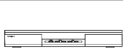
1.2.1 The front panel
The front panel of the digital receiver has buttons to control the digital receiver, and specific lamps and a display to indicate its status. The following indicates what they mean:
STANDBY button switches the digital receiver between standby mode and operation mode. (On/Off)
CHANNEL a, c buttons move to the next or previous service. They are also used to navigate in the menus and interactive screens.
VOLUME b, d buttons increase and decrease the volume.
They are also used to change options for a menu item.
Front display displays the current time in standby mode, and displays the current service and status of the digital receiver in operation mode.

4 Introduction
1.2.2 The remote control
|
|
1 |
|
button switches the digital re- |
|
|
|
|
|
|
|
|
ceiver between standby mode and |
|
|
|
|
operation mode. (On/Off) |
|
|
|
2 |
button mutes the sound. Press |
|
|
|
|
||
|
|
|
again to switch it back on. |
|
|
|
3 |
UHF |
button is not used in this |
|
|
|
model. |
|
|
|
|
|
|
|
|
4 |
button switches the output of |
|
|
|
|
||
|
|
|
the TV SCART socket between the |
|
|
|
|
digital receiver and the device con- |
|
|
|
|
nected to the VCR SCART socket. |
|
|
|
|
See § 3.2.3 for more description. |
|
|
|
5 |
button sets a sleep timer. |
|
|
|
|
||
|
|
6 |
|
|
|
|
Numeric buttons are used to enter |
||
|
|
|
service numbers and menu options. |
|
|
|
7 |
button switches between the |
|
|
|
|
||
|
|
|
current service and the previously |
|
|
|
|
viewed one. |
|
|
|
8 |
button displays more informa- |
|
|
|
|
||
|
|
|
tion about the current program or |
|
|
|
|
a program highlighted in the elec- |
|
|
|
|
tronic program guide. |
|
9 |
GUIDE button displays the electronic program guide. (EPG) |
|||
10 |
button switches between television services and ra- |
|||
|
|
|
|
|
|
dio services. |
|
|
|
11 |
MENU |
button displays the main menu. It is also used to |
||
|
return to the previous menu from a submenu. |
|||
|
|
|
|
|
12  button is used to select an audio track and sound mode, or a video track of multifeed program.
|
|
|
|
|
|
|
|
|
|
|
|
|
|
|
|
|
1.2 Controlling the digital receiver 5 |
|
|
|
|
|
|
|
|
|
|
|
|
|
|
|
|
|
|
|
|
|
|
|
|
|||||||||||||||
13 |
|
V+ |
|
|
, V |
buttons increase and decrease the volume. They |
||||||||||||
|
|
|
|
|
|
|
|
|
|
|
|
|
|
|
|
|
||
|
are also used to change options for a menu item. |
|||||||||||||||||
|
|
|
|
|
|
|
|
|
|
|
|
|
|
|
|
|||
|
|
|
|
|||||||||||||||
14 |
|
P+ |
|
|
, |
P |
buttons move to the next or previous service. |
|||||||||||
|
|
|
|
|
|
|
|
|
|
|
|
|
|
|
|
|||
|
They are also used to navigate in the menus and interac- |
|||||||||||||||||
|
tive screens. |
|||||||||||||||||
15 |
|
OK |
|
|
button displays the service list. It is also used to |
|||||||||||||
|
|
|||||||||||||||||
|
select menu items. |
|||||||||||||||||
|
|
|
|
|
||||||||||||||
16 |
|
FAV |
|
|
button displays the favorite list. |
|||||||||||||
|
|
|||||||||||||||||
|
|
|
|
|
|
|
|
|
|
|||||||||
17 |
|
|
|
|
|
|
|
|
button is used to select a subtitle track. |
|||||||||
|
|
|
|
|
|
|
|
|
||||||||||
18 |
|
EXIT |
|
button is used to leave the current screen. |
||||||||||||||
|
|
|||||||||||||||||
|
|
|
|
|
|
|
|
|
|
|
|
|
|
|
|
|
|
|
19 |
|
|
|
|
|
|
button displays teletext. |
|||||||||||
|
|
|
|
|
|
|
|
|
||||||||||
20 |
|
|
|
|
|
|
|
|
|
|
|
|
|
|
button rewinds. Subsequent presses change the |
|||
|
|
|
|
|
|
|
|
|
|
|
|
|
|
|
||||
|
rewind speed. |
|||||||||||||||||
21 |
|
|
|
|
|
|
|
|
|
|
|
|
|
|
button plays a recorded program, or displays the |
|||
|
|
|
|
|
|
|
|
|
|
|
|
|
|
|
||||
|
progress bar for navigation when playback has already |
|||||||||||||||||
|
started. |
|
|
|||||||||||||||
22 |
|
|
|
|
|
|
|
|
|
|
|
|
|
|
button fast forwards. Subsequent presses change |
|||
|
|
|
|
|
|
|
|
|
|
|
|
|
|
|
||||
|
the playback speed. |
|||||||||||||||||
23 |
|
|
|
|
|
|
|
|
|
|
|
|
|
|
button starts slow motion playback. Subsequent |
|||
|
|
|
|
|
|
|
|
|
|
|
|
|
|
|||||
|
|
|
|
|
|
|
|
|
|
|
|
|
|
|
||||
|
presses change the playback speed. |
|||||||||||||||||
24 |
|
|
|
|
|
|
|
|
|
|
|
|
|
|
button is used to stop playback, to stop recording, |
|||
|
|
|
|
|
|
|
|
|
|
|
|
|
|
|||||
|
|
|
|
|
|
|
|
|
|
|
|
|
|
|
||||
|
or to jump back to live television from time-shifted tele- |
|||||||||||||||||
|
vision. |
|
|
|||||||||||||||
25 |
|
|
|
|
|
|
|
|
|
|
|
|
button starts recording. |
|||||
|
|
|
|
|
|
|
|
|
|
|
|
|
||||||
26 |
|
|
|
|
|
|
|
|
|
|
|
|
button pauses live television or playback of a recorded |
|||||
|
|
|
|
|
|
|
|
|
|
|
|
|||||||
|
|
|
|
|
|
|
|
|
|
|
|
|
||||||
|
program. |
|||||||||||||||||
27 |
|
|
|
|
|
|
|
|
|
|
|
|
button changes the position of the sub-screen coun- |
|||||
|
|
|
|
|
|
|
|
|
|
|
|
|
||||||
terclockwise.

6 Introduction
28  button changes the position of the sub-screen clock-
wise.
29 SAT button displays the satellite list with their service list, and swaps the sub-picture with the main picture. See § 5.6 for more description.
30  button displays, minifies or hides the sub-screen. See § 5.6 for detailed description.
31  button makes a bookmark on playback or time shift.
32  button plays from the next bookmark position.
33  button is used to edit a recording.
34  button displays the list of recorded programs that have been saved on the hard disk of the digital receiver. See § 7.2 for more description.
35  button displays the service list for sub-screen, or spec-ifies a block for repeated playback.
36 N/P button is not used in this model.
The  ,
,  ,
,  ,
,  and
and  buttons have additional different functions per menu besides their own function. They will be guided by on-screen help.
If the remote control does not work, please check the remote control mode. There are 4 modes with this remote control. You can alter the mode by pressing two buttons simultaneously as follows:
•Mode 1:  + 1
+ 1
•Mode 2:  + 2
+ 2
•Mode 3:  + 3
+ 3
•Mode 4:  + 4
+ 4
The mode 1 will work at default.
1.3 What is common interface? 7
1.3What is common interface?
Some broadcasts are scrambled so that only paid subscribers can enjoy them. Scrambled services can only be viewed with a Conditional Access Module (CAM) and a subscription card belonging with the scrambling system.
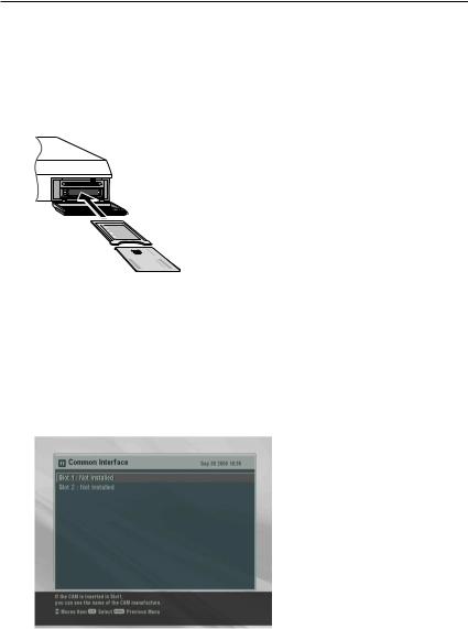
Common Interface (CI) is an interface for conditional access modules. The front of the digital receiver has two common interface slots.
To watch a pay service, you should take the following steps:
1.Purchase a conditional access module and a subscription card for the pay service you want to watch.
2.Insert the subscription card into the conditional access module.
3.insert the conditional access module to a common interface slot on the front of the digital receiver.
To view the information about the module and subscription card inserted to the digital receiver, select the Information >
Common Interface menu.

8 Setup
Chapter 2
Setup
2.1Unpacking
Before going any further, check that you have received the following items with your digital receiver.
•Remote control unit
•Two batteries for the remote control (AAA 1.5 V)
•One power cord
•One WLAN antenna
•A copy of this user guide
2.2Safety precautions
Please read the following safety precautions carefully.
•The mains power must be 90 to 250 volt. Check it before connecting the digital receiver to the wall outlet. For the power consumption of the digital receiver, refer to Table 2.1.
•The wall outlet should be near the equipment. Do not run an extention lead to the unit.

2.3 Rear panel connections 9
•Do not expose the digital receiver to any moisture. The digital receiver is designed for use indoors only. Use dry cloth when cleaning the digital receiver.
•Place the digital receiver on a firm and level surface.
•Do not place the digital receiver close to heat emitting units or in direct sunlight, as this will impair cooling. Do not lay any objects such as magazines on the digital receiver. When placed in a cabinet, make sure there is a minimum space of 10 centimeters around it. For the physical specification of the digital receiver, refer to Table 2.2.
•Protect the power cord from being walked on or pinched. If wires are exposed or cord is damaged, do not use the receiver and get cord replaced.
•Never open the digital receiver casing under any circumstances. Warranty will be void.
•Refer all servicing to an electronics qualified service technician.
Table 2.1: Power specification
Input voltage |
90 to 250 V AC, 50/60 Hz |
Power consumption |
45 W at maximum in operation |
|
8 W in standby |
|
|
Table 2.2: Physical specification |
|
|
|
Size |
430 60 265 mm |
Weight |
4.3 kg |
Operating temperature |
0 to 45 °C |
Storage relative humidity 5 to 95 %
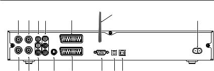
2.3 Rear panel connections
The TF 6000 PVR has a wide range of connections on the back panel.
10 Setup
|
|
|
|
|
14 |
1 |
3 |
5 |
7 |
9 |
15 |
|
|
VIDEO |
|
|
|
|
|
|
Y |
|
WLAN ANT |
LNB 1 IN |
LNB 2 IN |
L |
Pb |
|
TV |
|
|
R |
Pr |
|
|
IF 1 OUT |
IF 2 OUT |
AUDIO |
S-VIDEO |
|
|
|
|
|
|
VCR |
RS-232 |
S/PDIF |
USB |
2 |
4 |
6 |
8 |
10 |
12 |
11 13 |
Check up what connections your television set has in comparison with the digital receiver.
1 LNB 1 IN Broadcasting signal input socket for the first tuner.
2 IF 1 OUT Broadcasting signal output socket from the first tuner
3 LNB 2 IN Broadcasting signal input socket for the second tuner.
4 IF 2 OUT Broadcasting signal output socket from the second tuner.
5 VIDEO Composite video output socket for the television set (Yellow)
6 AUDIO L/R Stereo audio output socket for the television set or audio system. (Red/White)
7 Y/Pb/Pr Component video output socket for the television set. (Blue/Green/Red)
8 S-VIDEO Super video output socket for the television set.
TV |
Audio and video output socket for the tele- |
9 |
|
|
vision set. |
VCR |
Audio and video input / output socket for |
10 |
|
|
the video cassette recorder or suchlike. |

2.4 Connecting up your digital receiver 11
11 S/PDIF Dolby digital output socket for the audio system.
12 RS-232 Serial port for firmware update and data transfer.
USB |
USB port for firmware update and data trans- |
13 |
|
fer.
WLAN ANT Antenna for wireless local area network. |
|
14 |
|
AC INPUT Power cord socket. |
|
15 |
|
Table 2.3: Connectors specification |
|
|
|
VIDEO |
Composite video (CVBS) output |
AUDIO |
Left & right audio output |
S-VIDEO |
Super video (S-Video) output |
YPbPr |
Component video (YUV) output |
TV |
CVBS/S-Video/RGB/YUV video output |
|
Left & right audio output |
VCR |
CVBS video output |
|
Left & right audio output |
|
CVBS/S-Video/RGB/YUV video input for bypass |
|
Left & right audio input for bypass |
S/PDIF |
Dolby digital audio output |
RS-232 |
115.2 kbps at maximum |
USB |
2.0 |
|
|
2.4Connecting up your digital receiver
There are several ways to set up the digital receiver. Set up the digital receiver suitably to your television and other appliances. If you have any problem with your setup or need help, contact your dealer.
2.4.1 Connecting to the antenna
Whatever sort of connection you have between the digital receiver and the television, you need to connect the digital re-
12 Setup
ceiver to your television antenna so that it can receive digital television services.
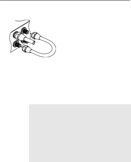
Connect the antenna cable to the LNB 1 IN socket on the back panel of the digital receiver.
However your digital receiver is connected to the television, you must ensure that there is a connection to both the LNB 1 IN and LNB 2 IN connectors on your digital receiver, so that both tuners work properly.
Normally you do that by using a loop cable to link from the IF 1 OUT connector to the LNB 2 IN connector.
If you have two antennas without DiSEqC switch, then you have to connect a cable from the other antenna directly to the LNB 2 IN connector rather than using the loop cable.
If you have another digital receiver, link it from the IF 2 OUT connector.
NOTE
The digital receiver can supply a current of 500 milliampere at maximum for antenna devices including LNB, DiSEqc switch and antenna rotor through each antenna input connection separately but not simultaneously. So if there are too many antenna devices to be supplied with power through antenna input connections simultaneously for a long time, your LNBs may lack power to operate. So it is recommended to link the IF 1 OUT connector to the LNB 2 IN connector with a loop cable even though the digital receiver is designed to operate over two antennas alternatively.
2.4.2 Connecting to your television
Between all the following connectors of your digital receiver, we recommend you use the first connector to get best picture
2.4 Connecting up your digital receiver 13
quality. If your television does not have the matching connector then use the next connector in the following order for best picture quality.
1.SCART connector (TV)
2.Component connector (YPbPr)
3.S-Video connector (S-VIDEO)
4.Composite connector (VIDEO)
You should configure audio and video settings after connecting up the digital receiver. See § 3.2 for detailed description.
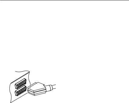
To use the SCART connector
For best results with a standard television set, you should use a SCART cable, plugging one end into the TV socket on the digital receiver and the other end into a free SCART socket on your television.
Some televisions have inputs via Component or S-Video connectors rather than SCART. If you have such a television, use an appropriate conversion cable to link the TV socket on the digital receiver to the matching socket on your television.
If you connect with a standard SCART cable, you do not have to make audio connections because the SCART connector can output stereo audio. But if you do with a conversion cable, such as SCART-to-Component, you have to make audio connections.
14 Setup
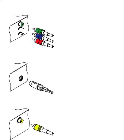
To use the component video connector
Y
Pb 

Pr 

You will need to obtain a component video cable (RCA cable) to use the component video connector. Plug one end of the cables into the Y (green), Pb (blue) and Pr (red) sockets on the digital receiver, and the other ends into the matching sockets on your television.
To use the S-Video connector
You will need to obtain a S-Video cable to use the S-Video connector. Plug one ends of the cable into the S-VIDEO socket on the digital receiver, and the other end into the matching socket on your television.
To use the composite video connector
You will need to obtain a composite video cable (RCA cable) to use the composite video connector. Plug one end of the cable into the VIDEO (yellow) socket on the digital receiver, and the other end into the matching socket on your television.
2.4 Connecting up your digital receiver 15
To connect the audio connectors
You will need to obtain an audio cable (RCA cable) to connect the audio connectors. Plug one ends of the cable into the AUDIO L (white) and AUDIO R (red) sockets on the digital receiver, and the other ends into the matching sockets on your television or audio system.
To enjoy Dolby digital audio, your television or audio system must be able to decode Dolby digital audio, and you will need to obtain a S/PDIF cable. Plug one end of the cable into the S/PIDF socket on the digital receiver, and the other end into the matching socket on your audio system.
2.4.3 Connecting to your video cassette recorder
The digital receiver also can output video to another appliance such as video cassette recorder or video receiver through an auxiliary SCART connector.
You will need to obtain a SCART cable to use the auxiliary SCART connector. Plug one end of the cable into the VCR socket on the digital receiver, and the other end into the matching socket on your video cassette recorder or suchlike.
2.4.4 Inserting batteries in the remote control
To insert the batteries, open the battery compartment by removing the lid, and then insert the batteries observing the polarity, which is marked on the base of the battery compartment.

16 Setup
If the digital receiver no longer reacts properly to remote control commands, the batteries may be flat. Be sure to remove used batteries. The manufacturer accepts no liability for damage resulting from leaking batteries.
NOTE
Batteries, including those which contain no heavy metals, may not be disposed of with household waste. Please dispose of used batteries in an environmentally sound manner. Find out about the legal regulations which apply in your area.
17
Chapter 3
Preference Settings
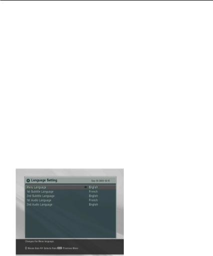
3.1Language settings
You can designate languages for menus, audio tracks and subtitle tracks.
Select the System Setting >
Language Setting menu.
Menu language
The digital receiver supports a lot of menu languages: Dutch, English, German, French, Italian, Russian, Turkish and so forth. Set the Menu Language option to your choice. Once you se-

18 Preference Settings
lect a language, the menu will be immediately displayed in the selected language.
Subtitle language
Set the 1st Subtitle Language and the 2nd Subtitle Language options to your choices. When you watch a program, if the program has the subtitle track of the langauge which is designated at the 1st Subtitle Language, it will be displayed. If the first laguage is not available but the second language is available, the subtitle of the second language will be displayed. If there is not any available language, no subtitle will be displayed.
Apart from this setting, you can select a subtitle track with the  button. See § 5.2.4 for detailed description.
Audio language
Set the 1st Audio Language and the 2nd Audio Language options to your choices. When you watch a program, if the program has the audio track of the language which is designated at the 1st Audio Language, it will be output. If the first language is not available but the second language is available, the audio of the second language will be output.
Apart from this setting, you can select an audio track with the  button. See § 5.2.3 for detailed description.
3.2Video and audio settings
You have to configure the video and audio settings appropriately to your television set and appliances.
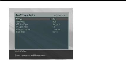
3.2 Video and audio settings 19
To configure the video and audio settings, select the System Setting > A/V Output Setting menu.
3.2.1 Television standard
The digital receiver supports two types of television standard. One is the PAL standard, and the other is the NTSC standard. PAL was adopted in European countries while NTSC is adopted in USA, Canada, Mexico and so forth.
If you have a PAL television, you have to set the TV Type option to PAL. In this case, if a service is broadcasted in NTSC standard, the digital receiver converts it into the PAL standard for your PAL television. However, its quality would somewhat fall. The opposite case brings about the same result.
The best thing is to watch PAL services with a PAL television and to watch NTSC services with a NTSC television. However, the multi television set is able to process both of them. So if you have an multi television set, set the TV Type option to Multi. With this option, the digital receiver will output them without standard conversion. This setting is most recommended especially if you are not sure what standard television you have.
3.2.2 Color model
Through the TV SCART connector, the digital receiver is able to output video in various color models. If you have the digital receiver linked to your television from this connector, you

20 Preference Settings
should set the Video Output option to your desired color model. If you have connected them by RCA connector at which VIDEO reads on the back panel of the digital receiver, you do not have to set this option because the digital receiver outputs CVBS video through RCA connector independent of SCART connector.
However, If you have connected them by S-VIDEO connector, you have to set this option to S-Video because the output through S-Video connector comes from the SCART interface. Similarly, if you have done by YUV connectors (Y, Pb and Pr), you have to set this option to YUV because of the same reason.
It is known in general that the RGB color model provides the best video quality with little difference from the YUV color model but the CVBS color model does the least. So RGB would be most desirable for this option.
3.2.3 Video cassette recorder
You would have the digital receiver linked to your video cassette recorder or such an appliance from the VCR SCART. The digital receiver will operate differently depending on the setting of the VCR Scart Type option. If the option is set to Standard, the digital receiver will pass the video from the video recorder to your television when the video recorder starts playback. But if the option is set to External A/V, the digital receiver will not pass the video even though the video recorder starts playback. To pass it, you have to press  button.
NOTE
In this case, it is impossible that the digital receiver records the video that the video recorder plays back because the digital receiver is just a bypass for the video recorder.
3.2.4 Television aspect ratio
If you have a wide-screen television, set the TV Aspect Ratio option to 16:9.
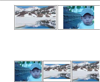
3.2 Video and audio settings 21
You can enjoy well both wide-screen programs and normalscreen programs with your wide-screen television as the above figures show. The left figure shows a wide picture displayed in the wide screen, and the right figure shows a normal picture displayed in the wide screen.
If you have a normal-screen television, set the TV Aspect Ratio option to 4:3.
You cannot fully enjoy wide-screen programs with your normalscreen television as the above figures show. The left figure shows a normal picture displayed in the normal screen. To watch wide-screen programs in the shape like the center figure, set the Display Format option to Letter Box. Wide-screen pictures then will be reduced to fit to the width of the normal screen. Otherwise to watch them in the shape like the right figure, set the option to Center extract. Wide-screen pictures then will be cut out on the left and right sides equally to fit to the width of the normal screen.
3.2.5 Sound mode
Basically, there are two audio sources as you can find two audio sockets on the back panel of the digital receiver. You can
22 Preference Settings
enjoy only one source or both of them in either stereo or mono. Set the Sound Mode option as you desire.
Apart from this setting, you can change the sound mode with the  button. See § 5.2.3 for detailed description.
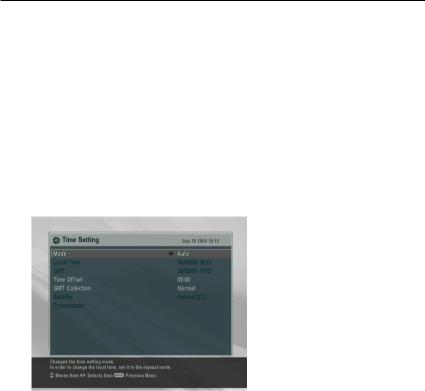
3.3Local time setting
You should set your local time for timer events. If you did not set the local time right, the program time table provided by the electronic program guide may also be distrustful. Refer the electronic program guide to § 5.3.
Select the System Setting > Local Time Setting menu.
You can set the local time either as Manual or Auto using Greenwich Mean Time (GMT). However, it is recommended to use the auto setting.
To set the local time using the auto setting, follow these steps:
1.Set the Mode option to Auto; then the Time Offset option becomes enabled.
2.Set the Time Offset option to the time difference between your time zone and GMT referring to Table 3.1.
3.Make sure that your local time is correctly displayed on the Local Time option.

3.3 Local time setting 23
Table 3.1: Time offset table
Time offset |
City |
GMT 12:00 |
Eniwetok, Kwajalein |
GMT 11:00 |
Midway Island, Samoa |
GMT 10:00 |
Hawaii |
GMT 09:00 |
Alaska |
GMT 08:00 |
Pacific Time US, Canada |
GMT 07:00 |
Mountain Time US, Canada |
GMT 06:00 |
Central Time US, Canada, Mexico City |
GMT 05:00 |
Eastern Time US, Canada, Bogota, Lima |
GMT 04:00 |
Atlantic Time Canada, La Paz |
GMT 03:30 |
Newfoundland |
GMT 03:00 |
Brazil, Georgetown, Buenos Aries |
GMT 02:00 |
Mid-Atlantic |
GMT 01:00 |
Azores, Cape Verde Islands |
GMT |
London, Lisbon, Casablanca |
GMT + 1:00 |
Paris, Brussels, Copenhagen, Madrid |
GMT + 2:00 |
South Africa, Kaliningrad |
GMT + 3:00 |
Baghdad, Riyadh, Moscow, St. Petersburg |
GMT + 3:30 |
Tehran |
GMT + 4:00 |
Abu Dhabi, Muscat, Baku, Tbilisi |
GMT + 4:30 |
Kabul |
GMT + 5:00 |
Ekaterinburg, Islamabad, Karachi, Tashkent |
GMT + 5:30 |
Bombay, Calcutta, Madras, New Delhi |
GMT + 6:00 |
Almaty, Dhaka, Colombo |
GMT + 7:00 |
Bangkok, Hanoi, Jakarta |
GMT + 8:00 |
Beijing, Perth, Singapore, Hong Kong |
GMT + 9:00 |
Tokyo, Seoul, Osaka, Sapporo, Yakutsk |
GMT + 9:30 |
Adelaide, Darwin |
GMT + 10:00 |
Eastern Australia, Guam, Vladivostok |
GMT + 11:00 |
Magadan, Solomon Islands, New Caledonia |
GMT + 12:00 |
Fiji, Auckland, Wellington, Kamchatka |
|
|
To set the local time yourself, set the Mode option to Manual and enter your local time to the Local Time option with the numeric buttons. The time format is day/month/year 24hour:minute.
NOTE
Daylight saving adds one hour to the time when On and removes one hour when Off. When setting time offset via GMT,
24 Preference Settings
make sure time doesn’t include daylight saving.
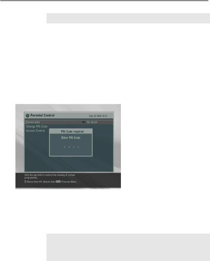
3.4Parental control
In general a television program is labeled a rating according to the level of violence, nudity and language of its content. When you are watching a program, you can check its program rating on the information box. Refer the information box to § 5.2.2.
You can prevent your children from watching specific programs by specifying a basis rating.
To specify a basis rating, select the System Setting > Parental Control menu; then you will be asked the Personal Identification Number (PIN). The number is initially set to ‘0000’.
If you wish to restrict 15 or above rated programs, set the Censorship option to 15 (age). Setting it to No block restricts no program; on the other hand, setting it to Total block restricts every program.
NOTE
If a program does not have any rating information, your rating setting will not take effect.
If anyone is trying to watch a program that is out of the basis rating, the person has to enter the personal identification number to override.
Loading...