

Page 1
INSTRUCTION MANUAL
IMAGING STATION
IS
SERIES
IS
201
IS
203
205
IS
Rev.1
Page 2

Page 3

FOREWORD
Thank you for purchasing the TOPCON Imaging Station IS series.
For the best performance of the instruments, please carefully read these instruc-
tions and keep them in a convenient location for future reference.
1
Page 4

General Handling Precautions
Before starting work or operation, be sure to check that the instrument is functioning
correctly with normal performance.
Do not aim the instrument directly into the sun
Aiming the instrument directly into the sun can result in serious damage to the eyes. Damage to
the instrument could also result from exposing the instrument’s objective lens to direct sunlight.
The use of a solar filter is suggested to alleviate this problem.
Setting the instrument on a tripod
When mounting the instrument on a tripod, use a wooden tripod when possible.
The vibrations that may occur when using a metallic tripod can effect the measuring precision.
Installing the tribrach
If the tribrach is installed incorrectly, the measuring precision could be effected. Occasionally
check the adjusting screws on the tribrach. Make sure the base fixing lever is locked and the base
fixing screws are tightened.
Guarding the instrument against shocks
When transporting the instrument, provide some protection to minimize risk of shocks. Heavy
shocks may cause the measurement to be faulty.
Carrying the instrument
Always carry the instrument by its handgrip.
Exposing the instrument to extreme heat.
Do not leave the instrument in extreme heat for longer than necessary. It could adversely affect its
performance.
Sudden changes of temperature
Any sudden change of temperature to the instrument or prism may result in a reduction of
measuring distance range, i.e when taking the instrument out from a heated vehicle.
Let instrument acclimate itself to ambient temperature.
Battery level check
Confirm battery level remaining before operating.
Memory back up
The back-up battery built in the instrument needs to be charged approximately 24hrs. before using
it for the first time after purchase. Connect the fully charged battery to the instrument in order to
charge the back-up battery.
Taking the battery out
Leaving the instrument without the battery for more than an hour will cause the memorized data to
be lost, due to low voltage of the back-up battery. Connect the battery as soon as possible or
execute RAM back-up.
No responsibility
TOPCON Corporation has no responsibility for loss of data stored in the memory in case
unexpected accidents.
Battery cover
Completely close the battery cover before using the IS. If the battery cover is not completely
closed, the IS will not operate normally, regardless of whether the battery or the external power
source is used.
If the battery cover is opened while the IS is in operation, operation will automatically be
suspended.
Power OFF
When turning off the power, be sure to turn off the IS’s power switch.
Do not turn off the power by removing the battery.
Before removing the battery, press the power switch and confirm that the power is off. Then
remove the battery.
While using the external power source, do not turn off the IS with the switch on the external power
source.
If the above-mentioned operating procedure is not followed, then, the next time that power is
turned on, it will be necessary to reboot the IS.
Maintenance for driving parts
Every 4,000~5,000 hours operation in total, change grease of driving parts.
Contact your dealer or TOPCON Head Office for the maintenance.
External power source
Use only recommended batteries or external power source. Use of batteries or an external power
source not recommended by us may result in equipment failure.
(For further information see Chapter 14 “BATTERY SYSTEM” .)
2
Page 5
Display for Safe Use
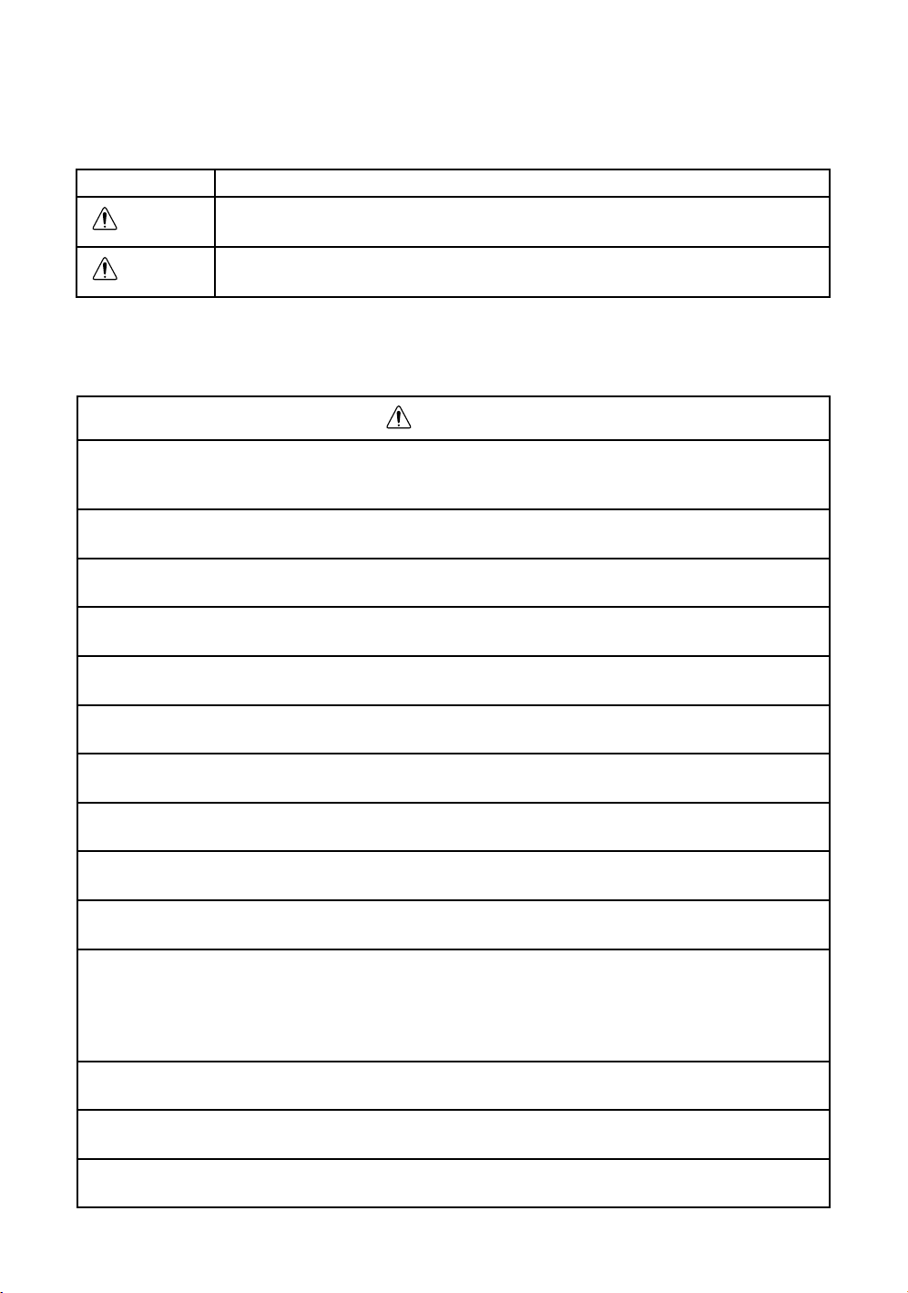
WARNING
In order to encourage the safe use of products and prevent any danger to the operator and others or damage
to properties, important warnings are put on the products and inserted in the instruction manuals.
We suggest that everyone understand the meaning of the following displays and icons before reading the
“Safety Cautions” and text.
Display Meaning
Ignoring or disregard of this display may lead to the danger of death or
serious injury.
CAUTION
•Injury refers to hurt, burn, electric shock, etc.
•Physical damage refers to extensive damage to buildings or equipment and furniture.
Ignoring or disregard of this display may lead to personal injury or physical damage.
Safety Cautions
WARNING
•There is a risk of fire, electric shock or physical harm if you attempt to disassemble or
repair the instrument yourself.
This is only to be carried out by TOPCON or an authorized dealer, only!
•Cause eye injury or blindness.
Do not look at the sun through a telescope.
•Laser beams can be dangerous, and can cause eye injury's if used incorrectly.
Never attempt to repair the instrument yourself.
•Cause eye injury or blindness.
Do not stare into beam.
•High temperature may cause fire.
Do not cover the charger while it is charging.
•Risk of fire or electric shock.
Do not use damaged power cable, plug and socket.
•Risk of fire or electric shock.
Do not use a wet battery or charger.
•May ignite explosively.
Never use an instrument near flammable gas, liquid matter, and do not use in a coal mine.
•Battery can cause explosion or injury.
Do not dispose in fire or heat.
•Risk of fire or electric shock.
Do not use any power voltage except the one given on manufacturers instructions.
•To reduce the risk of hazards, use only CSA/UL certified power supply cord set, cord is
Type SPT-2 or heavier, minimum No.18 AWG copper, one end is provided with a mouldedon male attachment plug cap (with a specified NEMA configuration), and the other end is
provided with a moulded-on female connector body (with a specified IEC non-industrial
type configuration).
•Battery can cause outbreak of fire.
Do not use any other type of charger other than the one specified.
•Risk of fire.
Do not use any other power cable other than the one specified.
•The short circuit of a battery can cause a fire.
Do not short circuit battery when storing it.
3
Page 6

•Risk of medical equipment malfunction.
Do not use the instrument in hospitals
•Risk of accident due to malfunction caused by radio waves affecting automatic control operations.
Do not use the instrument near automatic control equipment, such as automatic doors.
•Risk of airplane instrument malfunction.
Do not use the instrument on airplanes.
•Risk of implantable cardiac pacemaker malfunction caused by radio waves.
Ensure that the instrument is 22cm or farther away from implantable cardiac pacemakers.
4
Page 7

CAUTION
•Do not connect or disconnect equipment with wet hands, you are at risk of electric
shocks if you do!
•Use of controls or adjustment or performance of procedures other than those specified
herein may result in hazardous radiation exposure.
•Let the laser beam reach the aimed object or the target without anybody else in the laser
beam path. In case you operate laser beam open, avoid radiating laser beam to the height
of man's head. It is quite possible for the beam to enter into one's eyes, and it is possible
to lose visual sight temporarily, and lose one's caution and awareness of other dangers
- avoid glaring beam.
•Risk of injury by overturn the carrying case.
Do not stand or sit on the carrying cases.
•Please note that the tips of tripod can be hazardous, be aware of this when setting up or
carrying the tripod.
•Risk of injury by falling down the instrument or case.
Do not use a carrying case with a damaged which belts, grips or latches .
•Do not allow skin or clothing to come into contact with acid from the batteries, if this does
occur then wash off with copious amounts of water and seek medical advice.
•A plumb bob can cause an injury to a person if used incorrectly.
•It could be dangerous if the instrument falls over, please ensure you attach a handle to
the instrument securely.
•Ensure that you mount the tribrach correctly, failing to do so may result in injury if the
tribrach were to fall over.
•It could be dangerous if the instrument falls over, please check that you fix the instrument to the tripod correctly.
•Risk of injury by falling down a tripod and an instrument.
Always check that the screws of tripod are tightened.
•Risk of injury from rotation of the telescope.
Do not look into the telescope while wireless communication is in progress.
5
Page 8

User
1)This product is for professional use only!
The user is required to be a qualified surveyor or have a good knowledge of surveying, in order to
understand the user and safety instructions, before operating, inspecting or adjusting.
2)Wear the required protectors (safety shoes, helmet, etc.) when operating.
Exceptions from Responsibility
1)The user of this product is expected to follow all operating instructions and make periodic checks of the
product’s performance.
2)The manufacturer, or its representatives, assumes no responsibility for results of a faulty or intentional
usage or misuse including any direct, indirect, consequential damage, and loss of profits.
3)The manufacturer, or its representatives, assumes no responsibility for consequential damage, and
loss of profits by any disaster, (an earthquake, storms, floods etc.).
A fire, accident, or an act of a third party and/or a usage any other usual conditions.
4)The manufacturer, or its representatives, assumes no responsibility for any damage, and loss of profits
due to a change of data, loss of data, an interruption of business etc., caused by using the product or
an unusable product.
5)The manufacturer, or its representatives, assumes no responsibility for any damage, and loss of profits
caused by usage except for explained in the user manual.
6)The manufacturer, or its representatives, assumes no responsibility for damage caused by wrong
movement, or action due to connecting with other products.
6
Page 9
Laser Safety
IS series uses the invisible laser beam to measure the distance.
IS series uses the visible laser beam for auto tracking, optical communication.
The IS series products are manufactured and sold in accordance with “Radiation Safety of Laser
Products, Equipment Classification, Requirements and User‘s Guide” (IEC Publication 60825-1) or
“Performance Standards for Light-Emitting Products” (FDA/BRH 21 CFR 1040) provided on the safety
standards for laser beam.
As per the said standards, IS series is classified as “Class 2 (CLASS II) Laser Products”.
The laser beam belongs not very dangerous type but we request you to keep and understand “Safety
standard for users” as mentioned in the manual instruction.
In case of any failure, do not disassemble the instrument. Contact TOPCON or your TOPCON dealer.
Laser class of each mode is as follows.
Mode Laser class
Distance measurement Class 1 (CLASS I)
Autotracking Class 2 (CLASS II)
Optical communication Class 2 (CLASS II)
Laser pointer Class 2 (CLASS II)
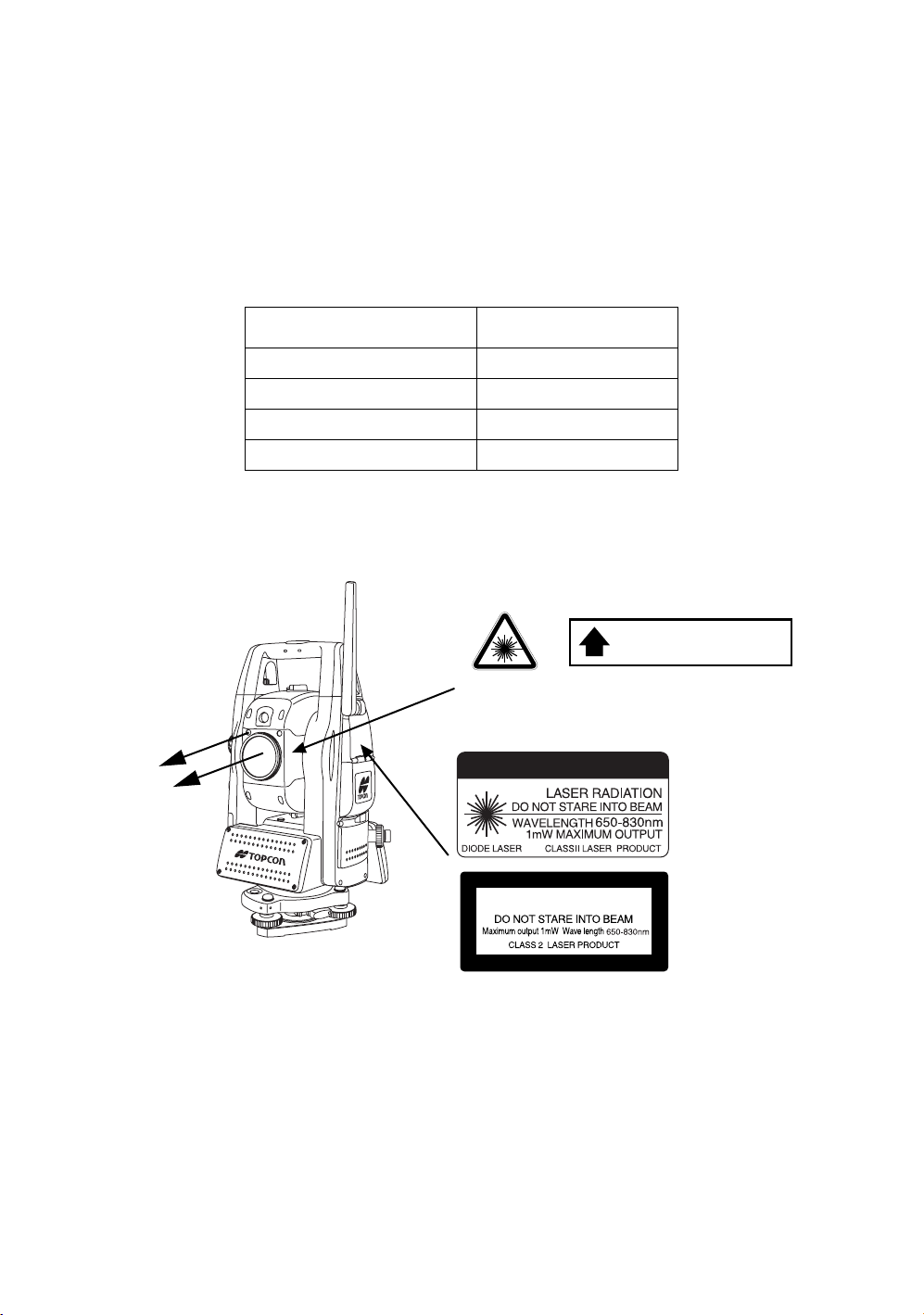
Labels
Find the labels which describes the caution and safety about the laser beam as follows in IS series.
We request you to replace it one anytime the caution labels are damaged or lost and paste a new one at the
same place. You can get the labels from Topcon or your dealer.
Beam aperture
AVO ID EXPOSURE
LASER LIGHT IS EMITTED
FROM THIS APERTURE
Warning Label
Aperture Label
CAUTION
LASER RADIATION
Explanatory Label
Each label is differed by the market.
7
Page 10
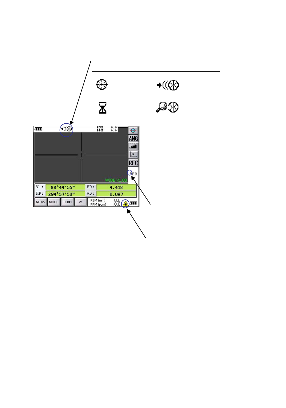
Symbol Mark while the Laser is Emitting.
These symbol marks will come on while the laser is working
Auto-collimating, Auto-tracking, Waiting, Searching (Class 1 (CLASS I) Laser)
Optical communication (Class 2 (CLASSI I) Laser)
Auto-collimating Auto-tracking
Waiting Searching
When distance is being measured
(
Class 1 (CLASS I) Laser)
When Laser Pointer light is ON
(
Class 2 (CLASS II) Laser)
8
Page 11

Contents
FOREWORD. . . . . . . . . . . . . . . . . . . . . . . . . . . . . . . . . . . . . . . . . . . . . . . . . . . . . . . . . 1
General Handling Precautions . . . . . . . . . . . . . . . . . . . . . . . . . . . . . . . . . . . . . . . . . . . . . . . . 2
Display for Safe Use . . . . . . . . . . . . . . . . . . . . . . . . . . . . . . . . . . . . . . . . . . . . . . . . . . . . . . . . 3
Safety Cautions. . . . . . . . . . . . . . . . . . . . . . . . . . . . . . . . . . . . . . . . . . . . . . . . . . . . . . . . . . . . 3
User. . . . . . . . . . . . . . . . . . . . . . . . . . . . . . . . . . . . . . . . . . . . . . . . . . . . . . . . . . . . . . . . . . . . . 6
Exceptions from Responsibility . . . . . . . . . . . . . . . . . . . . . . . . . . . . . . . . . . . . . . . . . . . . . . . . 6
Laser Safety . . . . . . . . . . . . . . . . . . . . . . . . . . . . . . . . . . . . . . . . . . . . . . . . . . . . . . . . . . . . . . 7
Labels . . . . . . . . . . . . . . . . . . . . . . . . . . . . . . . . . . . . . . . . . . . . . . . . . . . . . . . . . . . . . . . . . . . 7
Symbol Mark while the Laser is Emitting. . . . . . . . . . . . . . . . . . . . . . . . . . . . . . . . . . . . . . . . . 8
Contents . . . . . . . . . . . . . . . . . . . . . . . . . . . . . . . . . . . . . . . . . . . . . . . . . . . . . . . . . . . . . . . . . 9
1 NOMENCLATURE AND FUNCTIONS. . . . . . . . . . . . . . . . . . . . . . . . . . . . . . . . . . 12
1.1 Nomenclature . . . . . . . . . . . . . . . . . . . . . . . . . . . . . . . . . . . . . . . . . . . . . . . . . . . . . 12
1.2 Display. . . . . . . . . . . . . . . . . . . . . . . . . . . . . . . . . . . . . . . . . . . . . . . . . . . . . . . . . . . 14
1.2.1 Main Menu Contains . . . . . . . . . . . . . . . . . . . . . . . . . . . . . . . . . . . . . . . . . . . . . . . 14
1.2.2 Measurement Menu . . . . . . . . . . . . . . . . . . . . . . . . . . . . . . . . . . . . . . . . . . . . . . . 15
1.2.3 Display Marks . . . . . . . . . . . . . . . . . . . . . . . . . . . . . . . . . . . . . . . . . . . . . . . . . . . . 15
1.2.4 Display keys . . . . . . . . . . . . . . . . . . . . . . . . . . . . . . . . . . . . . . . . . . . . . . . . . . . . . 16
1.2.5 Shortcut Keys . . . . . . . . . . . . . . . . . . . . . . . . . . . . . . . . . . . . . . . . . . . . . . . . . . . . 16
1.3 Backlight, Key Light Adjustment . . . . . . . . . . . . . . . . . . . . . . . . . . . . . . . . . . . . . . . 17
1.3.1 How to Adjust Reducing Time of Backlight . . . . . . . . . . . . . . . . . . . . . . . . . . . . . 17
1.3.2 Adjust the Backlight Brightness by Manual . . . . . . . . . . . . . . . . . . . . . . . . . . . . . . 19
1.3.3 Selecting the Automatic Lighting Option . . . . . . . . . . . . . . . . . . . . . . . . . . . . . . . . 20
1.3.4 Selecting the Key Light Option . . . . . . . . . . . . . . . . . . . . . . . . . . . . . . . . . . . . . . . 21
1.4 RAM Data Backup. . . . . . . . . . . . . . . . . . . . . . . . . . . . . . . . . . . . . . . . . . . . . . . . . . 22
1.4.1 Execute the Backup Function . . . . . . . . . . . . . . . . . . . . . . . . . . . . . . . . . . . . . . . . 22
1.4.2 Set the Automatic Backup for Every Suspension . . . . . . . . . . . . . . . . . . . . . . . . . 24
1.4.3 Set the Restoration after Hardware Reset . . . . . . . . . . . . . . . . . . . . . . . . . . . . . . 24
1.5 Hardware Reset . . . . . . . . . . . . . . . . . . . . . . . . . . . . . . . . . . . . . . . . . . . . . . . . . . . 25
1.6 Cover Sensor . . . . . . . . . . . . . . . . . . . . . . . . . . . . . . . . . . . . . . . . . . . . . . . . . . . . . 25
1.7 Touch Panel Calibration . . . . . . . . . . . . . . . . . . . . . . . . . . . . . . . . . . . . . . . . . . . . . 26
1.8 Operating Panel Key . . . . . . . . . . . . . . . . . . . . . . . . . . . . . . . . . . . . . . . . . . . . . . . . 28
1.8.1 Operating Key . . . . . . . . . . . . . . . . . . . . . . . . . . . . . . . . . . . . . . . . . . . . . . . . . . . . 28
1.8.2 Turning OFF the Touch Panel Function . . . . . . . . . . . . . . . . . . . . . . . . . . . . . . . . 29
1.9 Power OFF . . . . . . . . . . . . . . . . . . . . . . . . . . . . . . . . . . . . . . . . . . . . . . . . . . . . . . . 29
1.10 Operation Key(Touch panel) . . . . . . . . . . . . . . . . . . . . . . . . . . . . . . . . . . . . . . . . . 30
1.11 Star Key Mode. . . . . . . . . . . . . . . . . . . . . . . . . . . . . . . . . . . . . . . . . . . . . . . . . . . . 32
1.11.1 Switching Measurement Distance Modes . . . . . . . . . . . . . . . . . . . . . . . . . . . . . . 36
1.11.2 Setting by Using Star Key . . . . . . . . . . . . . . . . . . . . . . . . . . . . . . . . . . . . . . . . . . 37
1.12 Auto Power Off . . . . . . . . . . . . . . . . . . . . . . . . . . . . . . . . . . . . . . . . . . . . . . . . . . . 38
1.13 Focus Function . . . . . . . . . . . . . . . . . . . . . . . . . . . . . . . . . . . . . . . . . . . . . . . . . . . 40
1.13.1 Manual Focus . . . . . . . . . . . . . . . . . . . . . . . . . . . . . . . . . . . . . . . . . . . . . . . . . . . 40
1.13.2 Assist Focus . . . . . . . . . . . . . . . . . . . . . . . . . . . . . . . . . . . . . . . . . . . . . . . . . . . . 40
1.13.3 Setting Focus Function. . . . . . . . . . . . . . . . . . . . . . . . . . . . . . . . . . . . . . . . . . . . 41
1.14 Rotating Method
1.14.1 Rotating by H/V Shuttle and H/V Jog . . . . . . . . . . . . . . . . . . . . . . . . . . . . . . . . . 42
1.14.2 Auto Inversion . . . . . . . . . . . . . . . . . . . . . . . . . . . . . . . . . . . . . . . . . . . . . . . . . . . 42
1.14.3 Rotating automatically to a required Horizontal and Vertical angle. . . . . . . . . . . 42
1.15 Using together with RC-3 Remote Control System. . . . . . . . . . . . . . . . . . . . . . . . 43
1.16 Using connecting with Personal Computer (PC). . . . . . . . . . . . . . . . . . . . . . . . . . 44
1.17 Using the USB Port . . . . . . . . . . . . . . . . . . . . . . . . . . . . . . . . . . . . . . . . . . . . . . . . 45
2 PREPARATION FOR MEASUREMENT . . . . . . . . . . . . . . . . . . . . . . . . . . . . . . . . 46
2.1 Power Connection. . . . . . . . . . . . . . . . . . . . . . . . . . . . . . . . . . . . . . . . . . . . . . . . . . 46
2.2 Setting Instrument Up For Measurement . . . . . . . . . . . . . . . . . . . . . . . . . . . . . . . . 47
2.3 Power Switch Key ON. . . . . . . . . . . . . . . . . . . . . . . . . . . . . . . . . . . . . . . . . . . . . . . 48
2.4 Battery Power Remaining Display. . . . . . . . . . . . . . . . . . . . . . . . . . . . . . . . . . . . . . 49
2.5 Vertical and Horizontal Angle Tilt Correction. . . . . . . . . . . . . . . . . . . . . . . . . . . . . . 50
2.5.1 Setting Tilt Correction by Operation Key . . . . . . . . . . . . . . . . . . . . . . . . . . . . . . . . 51
2.5.2 Correction of a Tilt Sensor setting error . . . . . . . . . . . . . . . . . . . . . . . . . . . . . . . . 51
2.6 Compensation of Systematic Error of Instrument . . . . . . . . . . . . . . . . . . . . . . . . . . 52
2.7 How to Enter Numerals and Alphabet Letters. . . . . . . . . . . . . . . . . . . . . . . . . . . . . 53
2.8 Data Memory Card . . . . . . . . . . . . . . . . . . . . . . . . . . . . . . . . . . . . . . . . . . . . . . . . . 57
9
Page 12

2.9 Active Sync . . . . . . . . . . . . . . . . . . . . . . . . . . . . . . . . . . . . . . . . . . . . . . . . . . . . . . . 58
2.9.1 Getting Connected . . . . . . . . . . . . . . . . . . . . . . . . . . . . . . . . . . . . . . . . . . . . . . . . 58
2.10 Confirming the Bluetooth® Device Address and Setting the PIN code. . . . . . . . . 58
2.11 Wireless LAN Function ON/OFF . . . . . . . . . . . . . . . . . . . . . . . . . . . . . . . . . . . . . . 59
2.12 Inclination of Prism and Measuring Error . . . . . . . . . . . . . . . . . . . . . . . . . . . . . . . 59
3 AUTOMATIC TRACKING / AUTOMATIC COLLIMATION . . . . . . . . . . . . . . . . . . 61
3.1 Automatic Tracking . . . . . . . . . . . . . . . . . . . . . . . . . . . . . . . . . . . . . . . . . . . . . . . . . 62
3.2 Automatic Collimation . . . . . . . . . . . . . . . . . . . . . . . . . . . . . . . . . . . . . . . . . . . . . . . 64
3.3 Range of Laser for Auto-tracking and Auto-collimating. . . . . . . . . . . . . . . . . . . . . . 65
3.4 Setting Parameters for Auto-Tracking. . . . . . . . . . . . . . . . . . . . . . . . . . . . . . . . . . . 66
3.4.1 Setting Items . . . . . . . . . . . . . . . . . . . . . . . . . . . . . . . . . . . . . . . . . . . . . . . . . . . . . 66
3.4.2 How to set the parameters . . . . . . . . . . . . . . . . . . . . . . . . . . . . . . . . . . . . . . . . . . 68
4 STANDARD MEASUREMENT MODE. . . . . . . . . . . . . . . . . . . . . . . . . . . . . . . . . . 69
4.1 Screen Displays . . . . . . . . . . . . . . . . . . . . . . . . . . . . . . . . . . . . . . . . . . . . . . . . . . . 69
4.1.1 Switching between Telescopic Image and Wide-Angle Image . . . . . . . . . . . . . . . 69
4.1.2 Changing the Image's Magnification . . . . . . . . . . . . . . . . . . . . . . . . . . . . . . . . . . . 70
4.1.3 Adjusting the Image's Brightness . . . . . . . . . . . . . . . . . . . . . . . . . . . . . . . . . . . . . 70
4.1.4 Switching the Cross-Hairs On and Off . . . . . . . . . . . . . . . . . . . . . . . . . . . . . . . . . 71
4.2 Angle Measurement . . . . . . . . . . . . . . . . . . . . . . . . . . . . . . . . . . . . . . . . . . . . . . . . 72
4.2.1 Measuring Horizontal Angle Right and Vertical Angle. . . . . . . . . . . . . . . . . . . . . . 72
4.2.2 Switching Horizontal Angle Right/Left . . . . . . . . . . . . . . . . . . . . . . . . . . . . . . . . . . 73
4.2.3 Measuring from the Required Horizontal Angle . . . . . . . . . . . . . . . . . . . . . . . . . . 74
4.2.4 Vertical Angle Percent Grade(%) Mode . . . . . . . . . . . . . . . . . . . . . . . . . . . . . . . . 75
4.2.5 Automatic Rotation to a Required Horizontal and Vertical Absolute Angle . . . . . . 76
4.3 Distance Measurement . . . . . . . . . . . . . . . . . . . . . . . . . . . . . . . . . . . . . . . . . . . . . . 77
4.3.1 Setting of the Atmospheric Correction. . . . . . . . . . . . . . . . . . . . . . . . . . . . . . . . . . 79
4.3.2 Setting of the Correction for Prism Constant. . . . . . . . . . . . . . . . . . . . . . . . . . . . . 79
4.3.3 Setting Measurement distance range of Non-prism long mode . . . . . . . . . . . . . . 79
4.3.4 Distance Measurement (Continuous Measurement). . . . . . . . . . . . . . . . . . . . . . . 81
4.3.5 Distance Measurement (Single/N-times Measurement) . . . . . . . . . . . . . . . . . . . . 82
4.3.6 Fine / Coarse Measuring Mode . . . . . . . . . . . . . . . . . . . . . . . . . . . . . . . . . . . . . . . 83
4.3.7 Stake Out (S.O). . . . . . . . . . . . . . . . . . . . . . . . . . . . . . . . . . . . . . . . . . . . . . . . . . . 84
4.4 Coordinate Measurement . . . . . . . . . . . . . . . . . . . . . . . . . . . . . . . . . . . . . . . . . . . . 86
4.4.1 Setting Coordinate Values of Occupied Point . . . . . . . . . . . . . . . . . . . . . . . . . . . . 86
4.4.2 Setting of the Instrument Height / Reflector(Prism) Height . . . . . . . . . . . . . . . . . . 88
4.4.3 Execution of Coordinate Measuring . . . . . . . . . . . . . . . . . . . . . . . . . . . . . . . . . . . 89
4.5 Data Output. . . . . . . . . . . . . . . . . . . . . . . . . . . . . . . . . . . . . . . . . . . . . . . . . . . . . . . 90
4.6 Data Output by [REC] Key . . . . . . . . . . . . . . . . . . . . . . . . . . . . . . . . . . . . . . . . . . . 91
4.7 Data output of IS series. . . . . . . . . . . . . . . . . . . . . . . . . . . . . . . . . . . . . . . . . . . . . . 92
5 PROGRAM MODE . . . . . . . . . . . . . . . . . . . . . . . . . . . . . . . . . . . . . . . . . . . . . . . . . 93
5.1 Setting a Direction Angle for Backsight Orientation(BS) . . . . . . . . . . . . . . . . . . . . . 94
5.2 Remote Elevation Measurement (REM) . . . . . . . . . . . . . . . . . . . . . . . . . . . . . . . . . 96
5.3 Missing Line Measurement (MLM) . . . . . . . . . . . . . . . . . . . . . . . . . . . . . . . . . . . . . 99
5.4 Repetition Angle Measurement (REP) . . . . . . . . . . . . . . . . . . . . . . . . . . . . . . . . . 101
5.5 AP-L1A Communication Emulator. . . . . . . . . . . . . . . . . . . . . . . . . . . . . . . . . . . . . 103
5.5.1 Activate AP-L1A communication Emulator
5.5.2 Setup for Communication . . . . . . . . . . . . . . . . . . . . . . . . . . . . . . . . . . . . . . . . . . 104
5.6 Edge Abstraction Mode. . . . . . . . . . . . . . . . . . . . . . . . . . . . . . . . . . . . . . . . . . . . . 105
5.6.1 Displayed Messages . . . . . . . . . . . . . . . . . . . . . . . . . . . . . . . . . . . . . . . . . . . . . . 106
6 PARAMETERS SETTING MODE. . . . . . . . . . . . . . . . . . . . . . . . . . . . . . . . . . . . . 107
6.1 Parameter Setting Options . . . . . . . . . . . . . . . . . . . . . . . . . . . . . . . . . . . . . . . . . . 108
6.1.1 Measurement . . . . . . . . . . . . . . . . . . . . . . . . . . . . . . . . . . . . . . . . . . . . . . . . . . . 108
6.1.2 Communication . . . . . . . . . . . . . . . . . . . . . . . . . . . . . . . . . . . . . . . . . . . . . . . . . . 109
6.1.3 Value Input . . . . . . . . . . . . . . . . . . . . . . . . . . . . . . . . . . . . . . . . . . . . . . . . . . . . . 110
6.1.4 Unit . . . . . . . . . . . . . . . . . . . . . . . . . . . . . . . . . . . . . . . . . . . . . . . . . . . . . . . . . . . 110
6.2 Setting Parameters . . . . . . . . . . . . . . . . . . . . . . . . . . . . . . . . . . . . . . . . . . . . . . . . 111
7 CHECK AND ADJUSTMENT. . . . . . . . . . . . . . . . . . . . . . . . . . . . . . . . . . . . . . . . 112
7.1 Checking and Adjusting of Instrument Constant . . . . . . . . . . . . . . . . . . . . . . . . . . 112
7.1.1 Checking of the accuracy of the non-prism mode / non-prism long mode . . . . . 112
7.2 Checking the Optical Axis . . . . . . . . . . . . . . . . . . . . . . . . . . . . . . . . . . . . . . . . . . . 113
7.2.1 Checking the optical axis of EDM and theodolite . . . . . . . . . . . . . . . . . . . . . . . . 113
7.2.2 Checking the optical axis of Laser pointer. . . . . . . . . . . . . . . . . . . . . . . . . . . . . . 117
10
Page 13

7.2.3 Inspection and Adjustment of Optic Axis for Auto -Tracking . . . . . . . . . . . . . . . . 119
7.3 Checking/Adjusting Each Function . . . . . . . . . . . . . . . . . . . . . . . . . . . . . . . . . . . . 121
7.3.1 Checking /Adjusting the Plate Level . . . . . . . . . . . . . . . . . . . . . . . . . . . . . . . . . . 122
7.3.2 Checking /Adjusting the Circular Level . . . . . . . . . . . . . . . . . . . . . . . . . . . . . . . . 122
7.3.3 Adjustment of the Vertical Cross-hair . . . . . . . . . . . . . . . . . . . . . . . . . . . . . . . . . 123
7.3.4 Collimation of the Instrument. . . . . . . . . . . . . . . . . . . . . . . . . . . . . . . . . . . . . . . . 124
7.3.5 Checking/Adjusting the Cross-Hairs on Telescopic/Wide-angle Images . . . . . . 125
7.3.6 Checking / Adjusting the Optical Plummet Telescope. . . . . . . . . . . . . . . . . . . . . 127
7.3.7 Adjustment of Vertical Angle 0 Datum. . . . . . . . . . . . . . . . . . . . . . . . . . . . . . . . . 128
7.4 How to Set the Instrument Constant Value . . . . . . . . . . . . . . . . . . . . . . . . . . . . . . 129
7.5 Compensation Systematic Error of Instrument . . . . . . . . . . . . . . . . . . . . . . . . . . . 130
7.5.1 Adjustment of Compensation Systematic Error of Instrument. . . . . . . . . . . . . . . 130
7.5.2 Showing Compensation Systematic Error of Instrument. . . . . . . . . . . . . . . . . . . 132
7.6 Self Checking Mode . . . . . . . . . . . . . . . . . . . . . . . . . . . . . . . . . . . . . . . . . . . . . . . 133
8 SETTING THE PRISM / NON-PRISM CONSTANT CORRECTION VALUE . . . . 135
9 SETTING ATMOSPHERIC CORRECTION . . . . . . . . . . . . . . . . . . . . . . . . . . . . . 137
9.1 Calculation of Atmospheric Correction . . . . . . . . . . . . . . . . . . . . . . . . . . . . . . . . . 137
9.2 Setting of Atmospheric Correction Value . . . . . . . . . . . . . . . . . . . . . . . . . . . . . . . 138
10 CORRECTION FOR REFRACTION AND EARTH CURVATURE . . . . . . . . . . . 143
10.1 Distance Calculation Formula . . . . . . . . . . . . . . . . . . . . . . . . . . . . . . . . . . . . . . . 143
11 POWER SOURCE AND CHARGING. . . . . . . . . . . . . . . . . . . . . . . . . . . . . . . . . 144
11.1 On-board Battery BT-65Q . . . . . . . . . . . . . . . . . . . . . . . . . . . . . . . . . . . . . . . . . . 144
12 DETACH/ATTACH OF TRIBRACH . . . . . . . . . . . . . . . . . . . . . . . . . . . . . . . . . . 146
13 SPECIAL ACCESSORIES . . . . . . . . . . . . . . . . . . . . . . . . . . . . . . . . . . . . . . . . . 147
14 BATTERY SYSTEM . . . . . . . . . . . . . . . . . . . . . . . . . . . . . . . . . . . . . . . . . . . . . . 149
15 PRISM SYSTEM. . . . . . . . . . . . . . . . . . . . . . . . . . . . . . . . . . . . . . . . . . . . . . . . . 150
16 PRECAUTIONS . . . . . . . . . . . . . . . . . . . . . . . . . . . . . . . . . . . . . . . . . . . . . . . . . 151
17 MESSAGE/ERROR DISPLAYS . . . . . . . . . . . . . . . . . . . . . . . . . . . . . . . . . . . . . 152
17.1 Message
17.2 Error
18 SPECIFICATIONS . . . . . . . . . . . . . . . . . . . . . . . . . . . . . . . . . . . . . . . . . . . . . . . 155
19 APPENDIX . . . . . . . . . . . . . . . . . . . . . . . . . . . . . . . . . . . . . . . . . . . . . . . . . . . . . 161
Dual Axis Compensation. . . . . . . . . . . . . . . . . . . . . . . . . . . . . . . . . . . . . . . . . . . . . . . . . . 161
20 INDEX . . . . . . . . . . . . . . . . . . . . . . . . . . . . . . . . . . . . . . . . . . . . . . . . . . . . . . . . . 163
11
Page 14
1 NOMENCLATURE AND FUNCTIONS
h
1 NOMENCLATURE AND FUNCTIONS
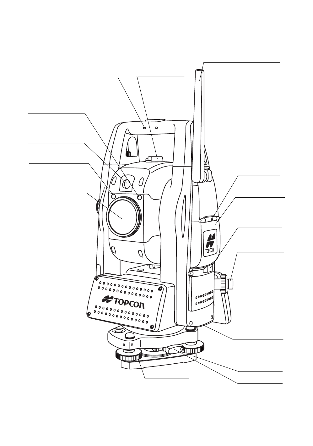
1.1 Nomenclature
Antenna
(for Wireless LAN , SS Wireless)
Carrying handle
Tr acking indicator
Camera(wide)
Laser aperture
(for Optical communication)
Objective lens/
Camera(telescope)/
Laser pointer
Laser aperture
Sighting collimator
Instrument
center mark
Card cover
Hardware reset switc
(Inside the cover)
Card cover lever
Optical plummet
telescope
12
USB connector
Base
Leveling screw
Tr ibrach fixing lever
Page 15
1 NOMENCLATURE AND FUNCTIONS
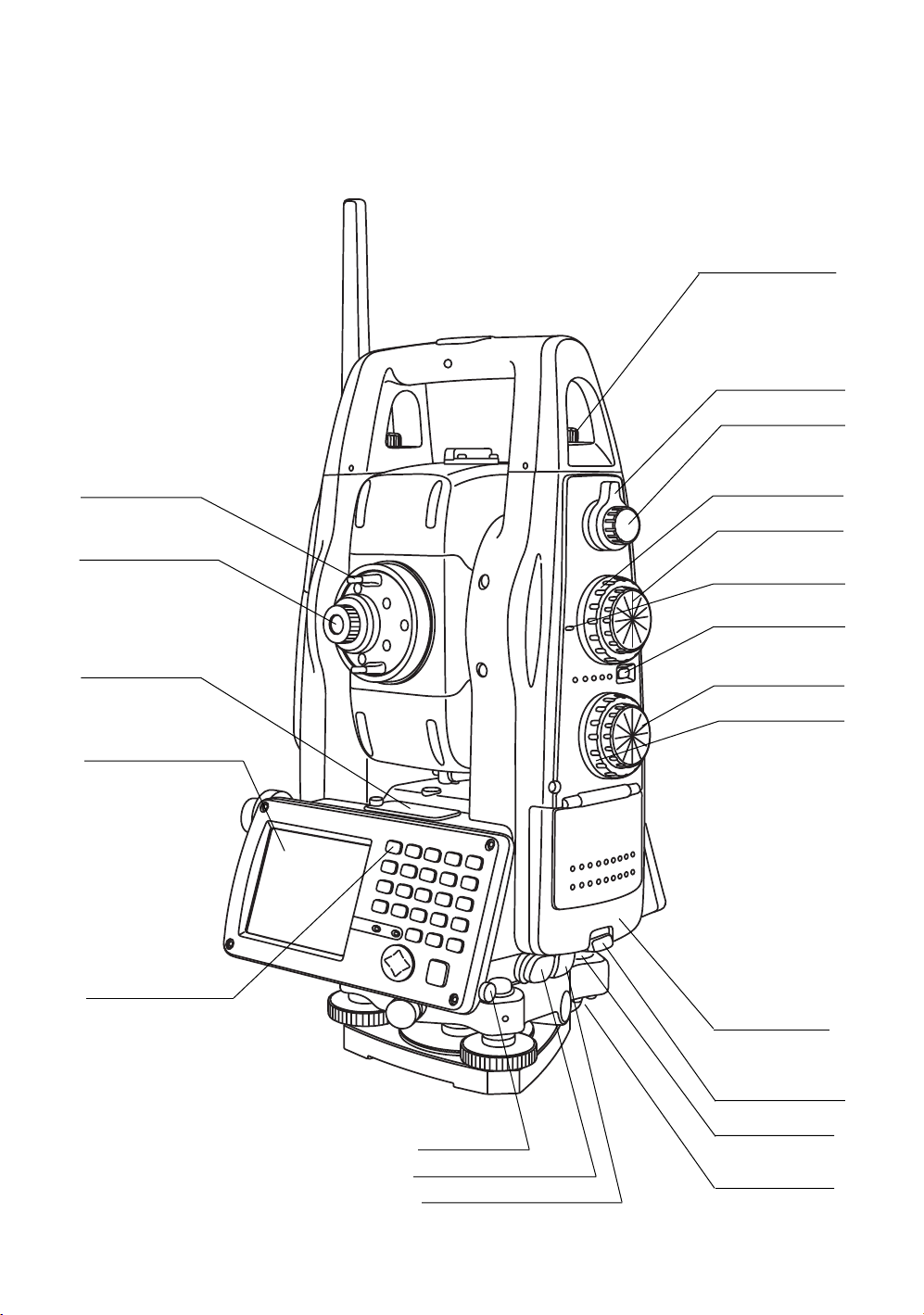
Handle fixing screw
Focus shuttle
Focus jog
Telescope grip
Telescope eyepiece
Plate level
Display window
(With touch panel)
Operation keys
Vertical shuttle
Vertical jog
Instrument
height mark
Power switch
Horizontal jog
Horizontal shuttle
Battery cover
Cover sensor
(Inside the cover)
Stylus pen
Serial Signal Connector
Power supply connector
Battery cover lever
Circular level
Adjusting screw
for circular level
13
Page 16
1 NOMENCLATURE AND FUNCTIONS
1.2 Display
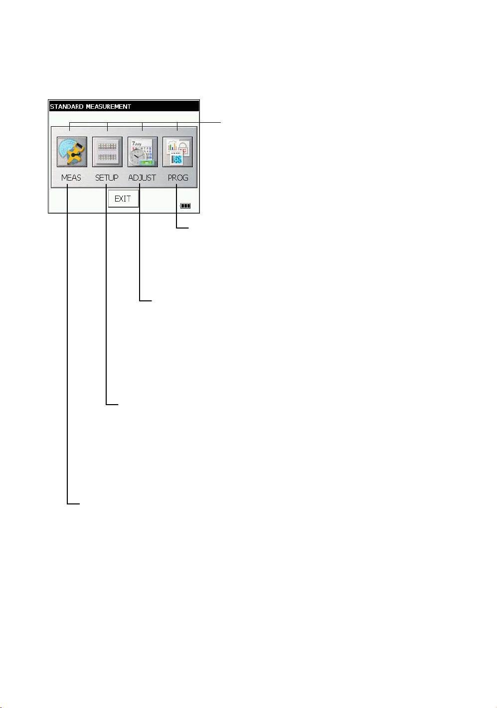
1.2.1 Main Menu Contains
The main menu contains as following items.
Select the menu by pressing icons.
ADJUSTMENT MODE
This mode is used for checking and adjustment.
• Error of vertical angle 0 datum
• Setting instrument constant value
• Compensation systematic error of Instrument
• Checking the optical axis of EDM
• Adjustment of optic axis for auto -tracking
• Self check
• Checking/Adjusting the Cross-Hairs on Images
(see Chapter 7 “CHECK AND ADJUSTMENT” .)
PARAMETERS SETTING MODE
This mode is used for follows
• Setting measurement
• Setting communication
• Value input
• Setting unit
The PARAMETERS SETTING MODE settled is
memorized even power is off.
(see Chapter 6 “PARAMETERS SETTING MODE” .)
Display icon
PROGRAM MODE
• Setting a direction angle for backsight orientation
• Remote elevation measurement
• Missing line measurement
• Repetition angle measurement
• Setting AP-L1A communication
(see Chapter 5 “PROGRAM MODE” .)
14
STANDARD MEASUREMENT MODE
This mode is used for follows
• Angle measurement
• Distance measurement
• Coordinate measurement
(see Chapter 4 “STANDARD MEASUREMENT MODE” .)
Page 17
1 NOMENCLATURE AND FUNCTIONS
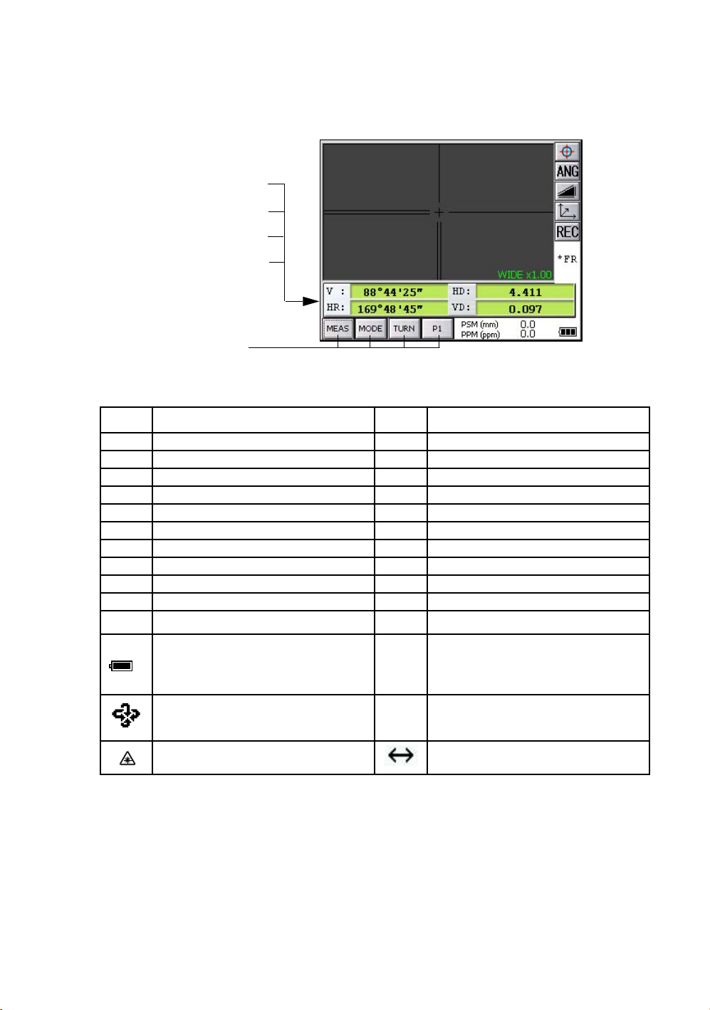
1.2.2 Measurement Menu
Example : Distance Mode
V-angle V : 88°44’25”
H-angle HR : 169°48’45”
Horizontal distance HD : 4.411m
Relative elevation VD : 0.097m
Operation keys
1.2.3 Display Marks
Display Contents Display Contents
VV-angle m Meter unit
V% Percent grade ft Feet unit
HR H-angle right F Fine mode
HL H-angle left C Coarse mode
HD Horizontal distance c Coarse 10mm mode
VD Relative elevation R Repeat measurement
SD Slope distance S Single measurement
NN coordinate N N-times measurement
EE coordinate PPM Atmospheric correction value
ZZ coordinate PSM Prism constant correction value
*
Battery Level Indicator
Refer to see Chapter 2.4 “Battery Power
Remaining Display” . for further
information.
Rotation Indicator
Refer to Section 1.14 “Rotating Method”
for further information.
EDM working NPM Non-Prism constant correction value
NP Non-prism mode
LNP Non-prism long mode
Laser emitting mark Setting Non-prism long range
15
Page 18
1 NOMENCLATURE AND FUNCTIONS
•
The symbol marks for Auto-tracking and Auto-collimating
Auto-collimating
Laser is emitting
(
)
The instrument is in auto-collimating
status.
Waiting (
Laser is emitting
The instrument is in waiting status.
Failure in auto-collimating.
(Laser is off)
The instrument could not find the
target prism during auto-collimating.
1.2.4 Display keys
KeysName of Key Function
Auto-tracking
(
Laser is emitting
)
The instrument is in auto-tracking
status.
)
Searching (
The instrument is searching a
Laser is emitting)
prism.
Auto-collimating
ANG
measuring key
measuring key
measuring key
REC REC key Result of measurement is transferred.
1.2.5 Shortcut Keys
Software Reset [Shift]+[Func]+[ESC]
Windows Start Menu [Ctrl]+[ESC]
Shortcut Commands
Windows CE
Task Manager
key
Angle
Distance
Coordinate
Tu rn the collimating ON/OFF.
To be angle measuring mode.
To be distance measuring mode.
To be coordinate measuring mode.
Continue tapping on an item
or
[Alt]+Tap on an item
[Alt]+[TAB]
to switch to another active program or to END Task on running program(s).
16
Page 19
1 NOMENCLATURE AND FUNCTIONS
1.3 Backlight, Key Light Adjustment
1.3.1 How to Adjust Reducing Time of Backlight
To conserve battery power, this instrument would automatically turn the backlight off or reduce the
backlight brightness by itself when it’s not in use.
In addition, the instrument can control the backlight brightness automatically by an equipped
illuminometer.
You can adjust the settings of this function to conserve more battery power or set your liking.
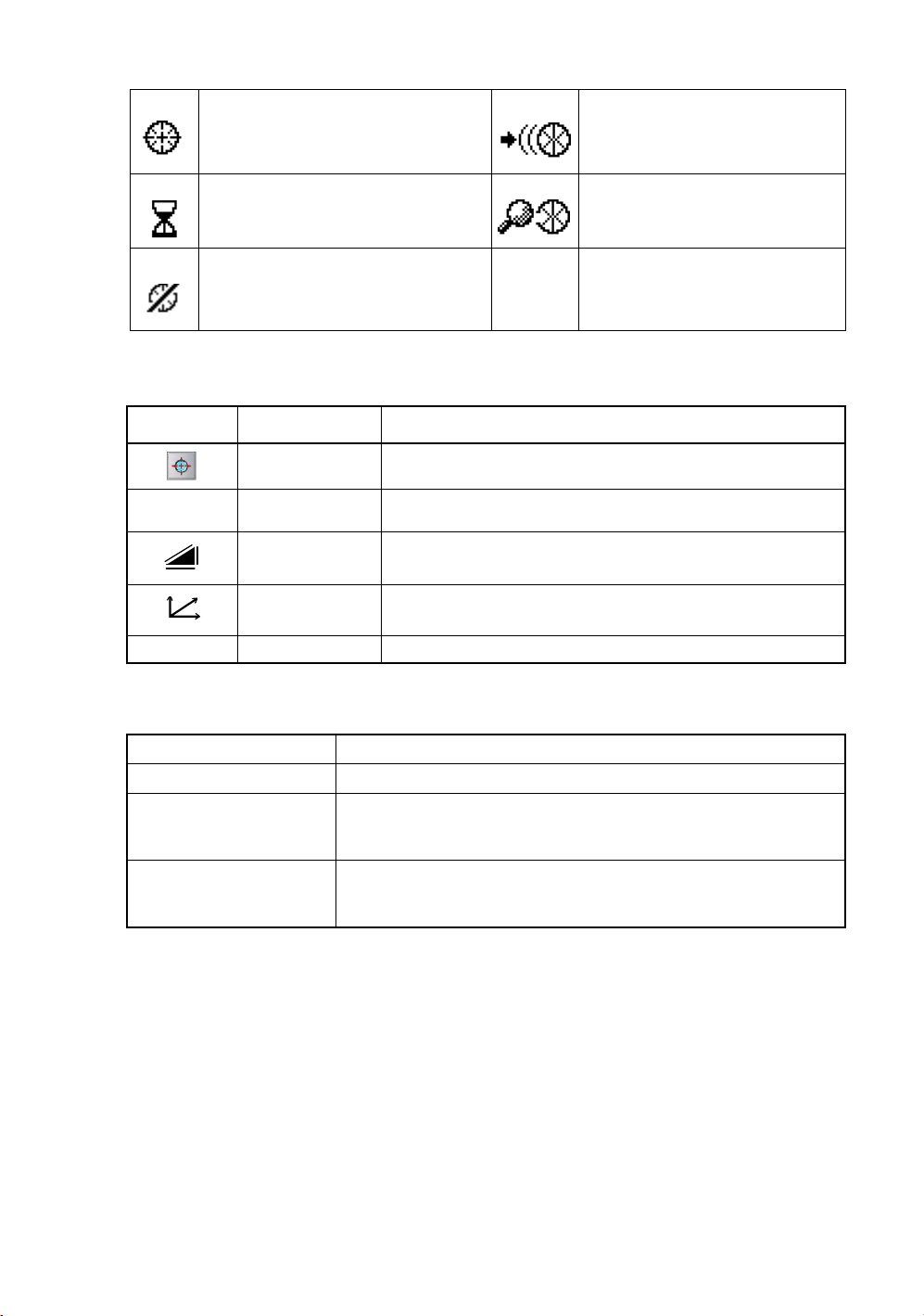
1
Press the icon [Start]-[Settings]-[Control Panel]-[Power].
You can see the "Power Properties" screen on Display.
2
Press the tab [Backlight].
You can see the "Backlight" screen on Display.
17
Page 20
1 NOMENCLATURE AND FUNCTIONS
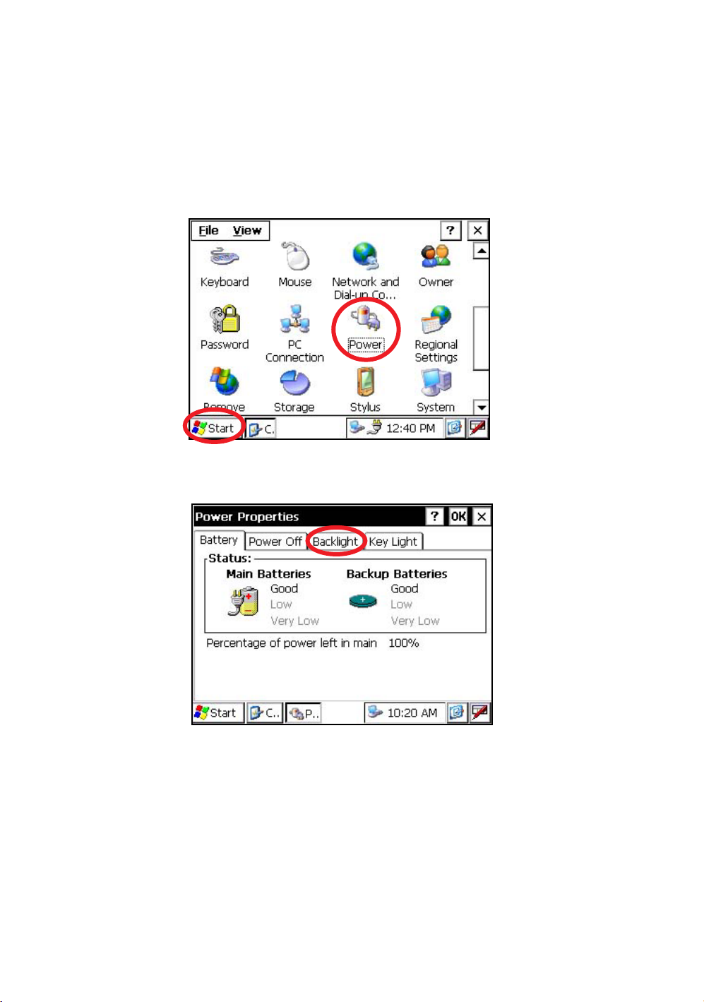
3
Press the time-menu down arrow to select the reducing time.
Factory setting is ‘3 minutes' as default.
4
Press the [OK] key on title bar. After that "Power Properties" screen will close automatically.
18
Page 21
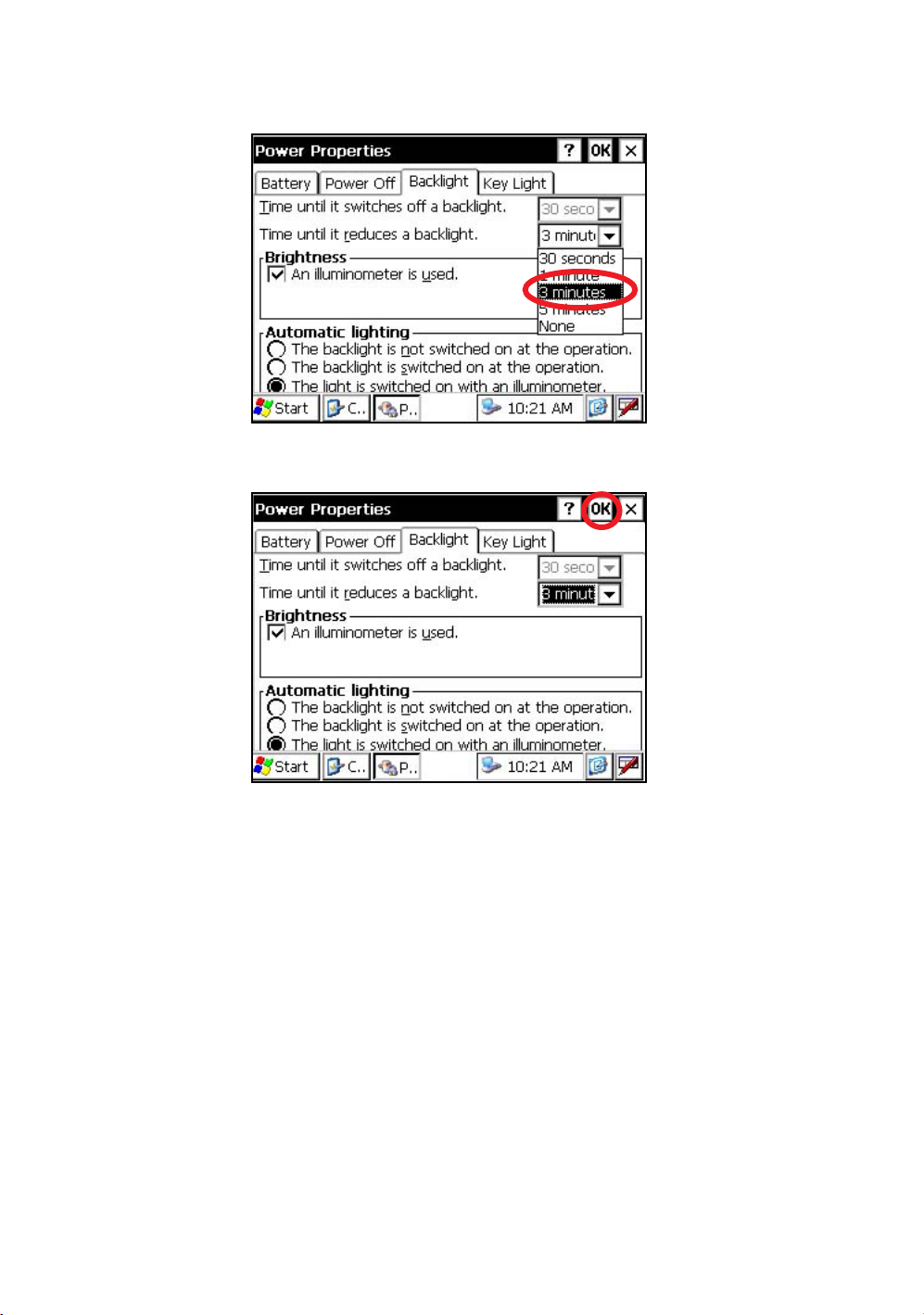
1.3.2 Adjust the Backlight Brightness by Manual
1
On the "Backlight" screen, please check it 'OFF' "An illuminometer is used.”.
(Factory setting is 'ON' as default)
The "Brightness adjusting slide bar” will be appeared on Display.
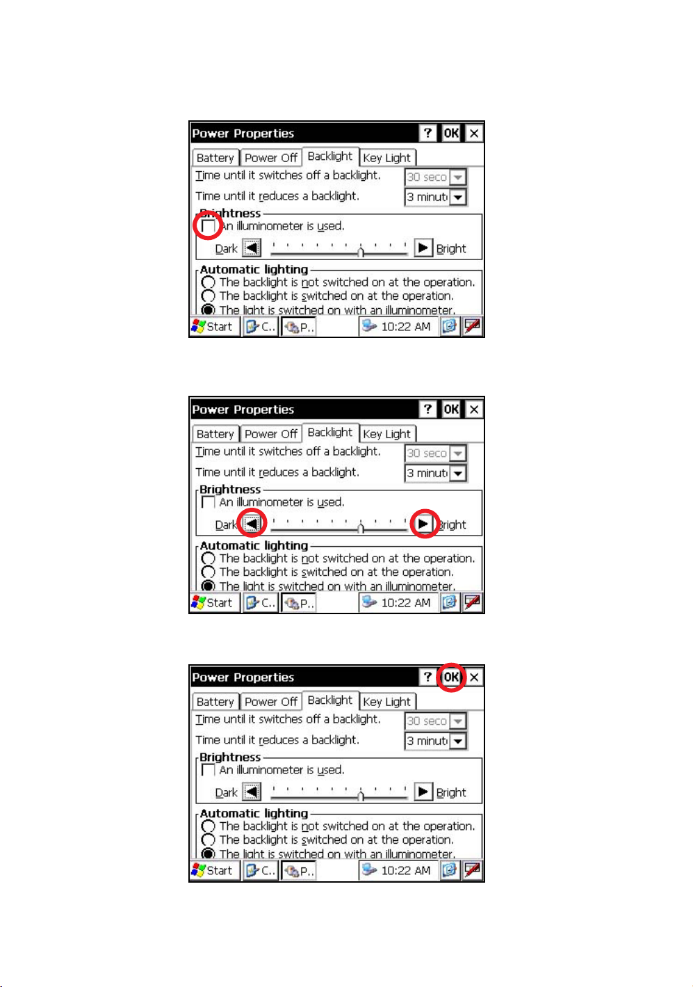
2
Adjust the brightness by pressing [Dark-Bright] button.
1 NOMENCLATURE AND FUNCTIONS
3
Press the [OK] key on title bar. After that "Power Properties" screen will close automatically.
19
Page 22
1 NOMENCLATURE AND FUNCTIONS
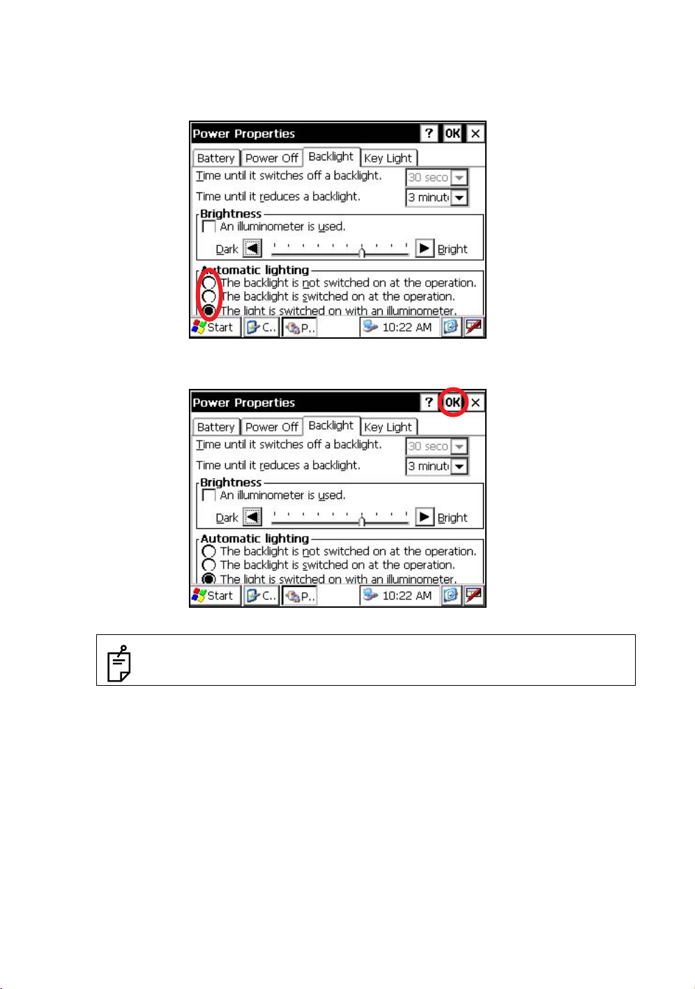
1.3.3 Selecting the Automatic Lighting Option
1
On the "Backlight" screen, select a Radio button from “Automatic lighting” column.
(Factory setting is “The light is switched on with an illuminometer.” as default)
2
Press the [OK] key on title bar. After that "Power Properties" screen will close automatically.
20
• The “Time until it switches off a backlight.” time-menu is not activate if “The light is
switched on with an illuminometer.” option is selected.
Page 23
1 NOMENCLATURE AND FUNCTIONS
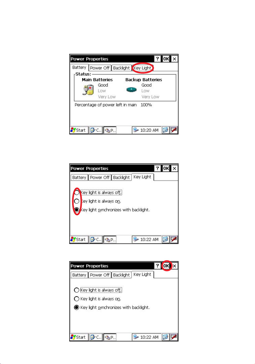
1.3.4 Selecting the Key Light Option
The Key Light option:
[Key light is always off, Key light is always on, Key light synchronizes with backlight]
1
Press the tab [Key Light].
You can see the "Key Light" screen on Display.
2
Select a Radio button.
(Factory setting is “Key light synchronizes with backlight.” as default)
3
Press the [OK] key on title bar. After that "Power Properties" screen will close automatically
21
Page 24
1 NOMENCLATURE AND FUNCTIONS
1.4 RAM Data Backup
If your device had not recharged during several days, the battery will be running down, and you would
lose all of data on the device other than that in the "Internal Disk (internal micro SD card)".
In addition, you might perform hardwarereset by the hardware problem or software problem. In this
case, you would lose all data same as the above.
You can use Backup function of the instrument in order to evade such kind of uneasiness. Your data will
be restored to latest condition 1) automatically when rebooting by using the Backup function.
The Backup function saves all data files of RAM (except for OS files), registry file and additionally
installed programs into named "Backup" folder in the "Internal Disk".
1) The conditions that you executed the backup function last.
* Restoring former backup data may be incomplete if you upgrade OS version.
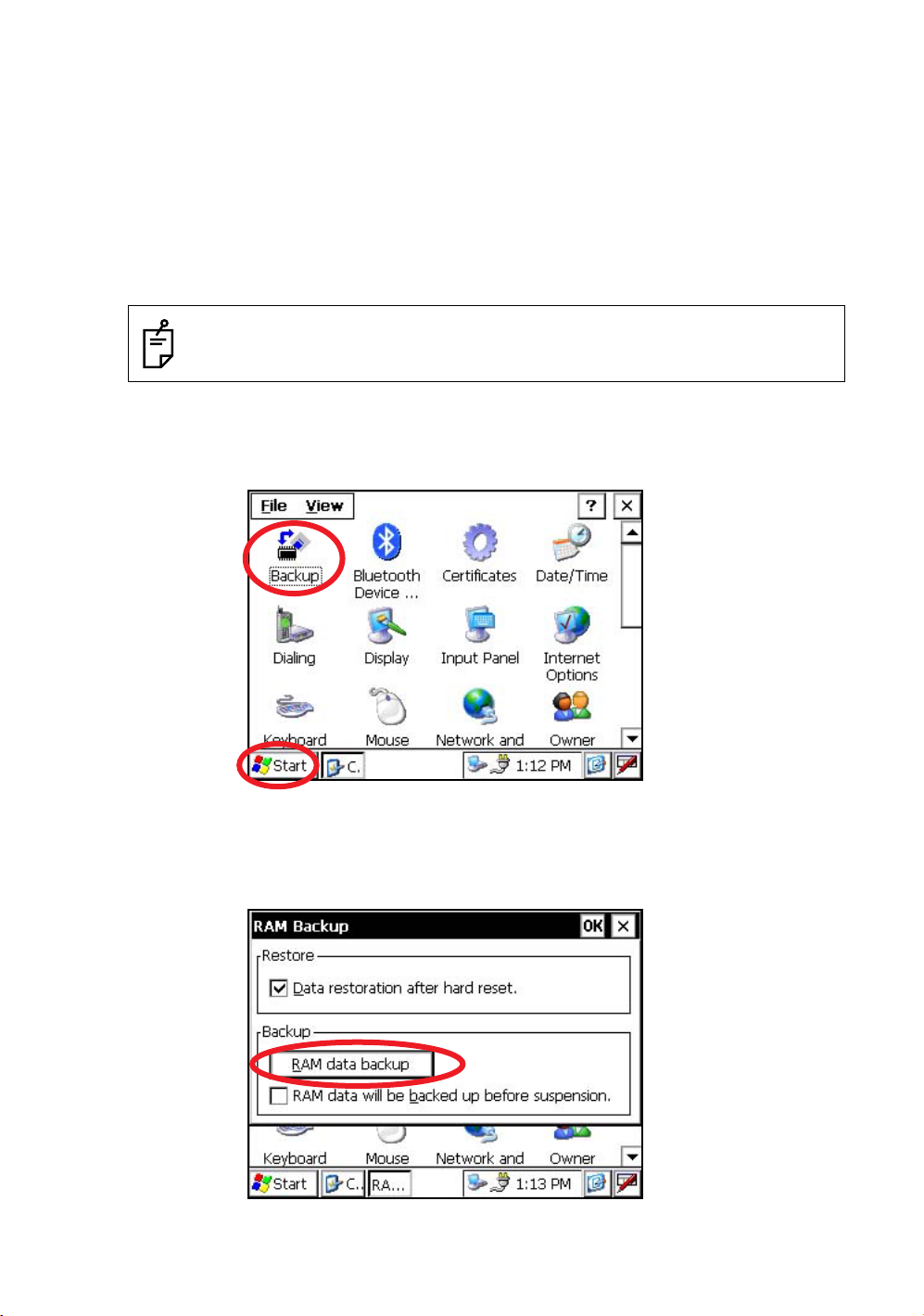
1.4.1 Execute the Backup Function
Make sure the mode is Windows CE mode.
1
Press the icon [Start]-[Settings]-[Control Panel]-[Backup].
22
You can see the "RAM Backup" screen on Display.
2
Press the [RAM data backup] key.
You can see the "Confirmation screen" on display.
Page 25
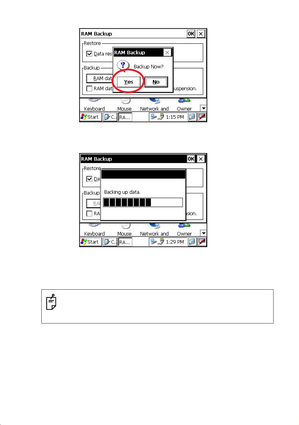
3
Press the [YES] key.
Backup function will start.
1 NOMENCLATURE AND FUNCTIONS
Return to "RAM Backup" screen automatically, when the data back up has been completed.
4
Press the [OK] key on title bar. After that "RAM Backup" screen will close automatically.
• Backing up data may be incomplete if remaining capacity of "Internal Disk" is not enough.
Please make sure the remaining capacity of "Internal Disk" before proceeding to the data
back up.
• Restoration will be impossible if you delete the "Backup" folder in the "Internal Disk".
23
Page 26
1 NOMENCLATURE AND FUNCTIONS
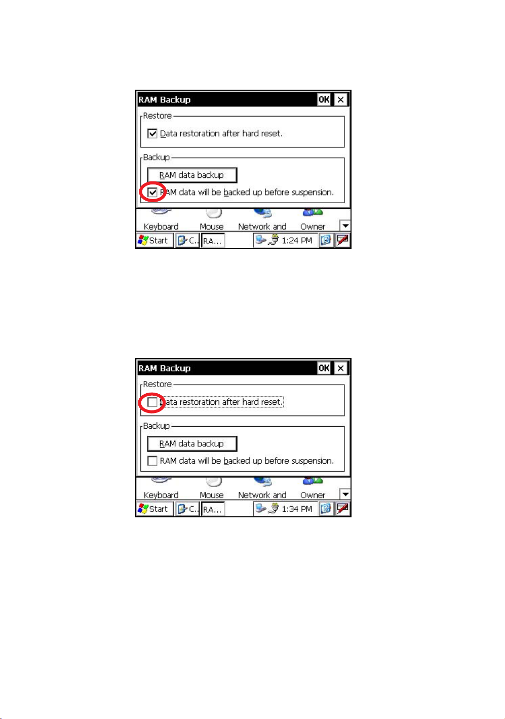
1.4.2 Set the Automatic Backup for Every Suspension
1
On the "RAM Backup" Screen, please check it 'ON' the "RAM data will be backed up before
suspension.".
(Factory setting is 'ON' as default)
2
Press the [OK] key on title bar. After that, "RAM Backup" screen will close automatically.
1.4.3 Set the Restoration after Hardware Reset
1
On the "RAM Backup" Screen, check it 'ON' the "Data restoration after hard reset.".
(Factory setting is 'ON' as default)
24
2
Press the [OK] key on title bar. After that, "RAM Backup" screen will close automatically.
Page 27
1 NOMENCLATURE AND FUNCTIONS
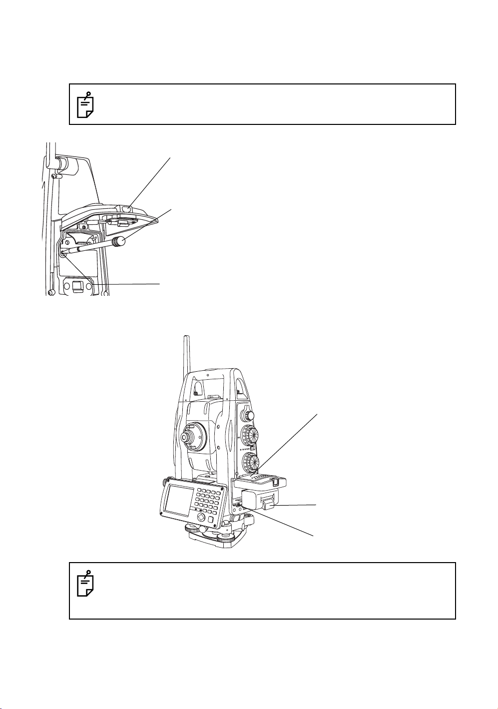
1.5 Hardware Reset
If your instrument not responding or an application hangs, please try to perform a software reset first.
Still, when useless, please perform hardware reset.
You will lose all of data on the device other than that in the "Internal Disk" after hardware reset
and will need to reinstall the applications and the data you install on your instrument.
Card cover lever
1
2
Stylus pen
Hardware reset switch
3
1.6 Cover Sensor
Completely close the battery cover before using the instrument.
Pull the card cover lever to open the card cover.
Insert the stylus into the unit of hardware reset
switch.
Press the switch for two seconds.
The instrument will reboot.
Battery cover
Battery
Cover sensor
• If the battery cover is not completely closed, the instrument will not operate normally,
regardless of whether the battery or the external power source is used.
• If the battery cover is opened while the instrument is in operation, operation will
automatically be suspended.
25
Page 28
1 NOMENCLATURE AND FUNCTIONS
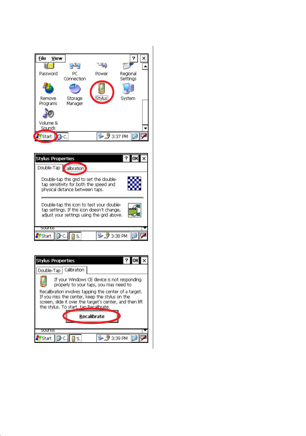
1.7 Touch Panel Calibration
If your instrument is not responding properly to your taps, you may need to calibrate the touch panel.
• How to calibrate the touch panel
1
Press the icon [Start]-[Settings]-[Control Panel][Stylus].
You can see the "Stylus Properties" screen on
Display.
2
Press the tab “Calibration”.
26
3
Press the [Recalibrate] key.
Page 29
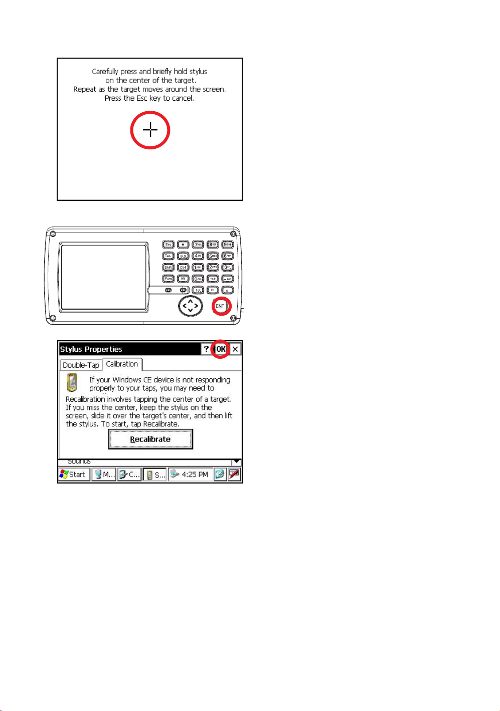
1 NOMENCLATURE AND FUNCTIONS
4
Using the stylus pen, press the center of the
targets on the screen.
5
After pressing all targets (5 points), press the
[ENT] key, or tap the display.
6
Press the [OK] key.
The display returns to previous menu.
27
Page 30
1 NOMENCLATURE AND FUNCTIONS
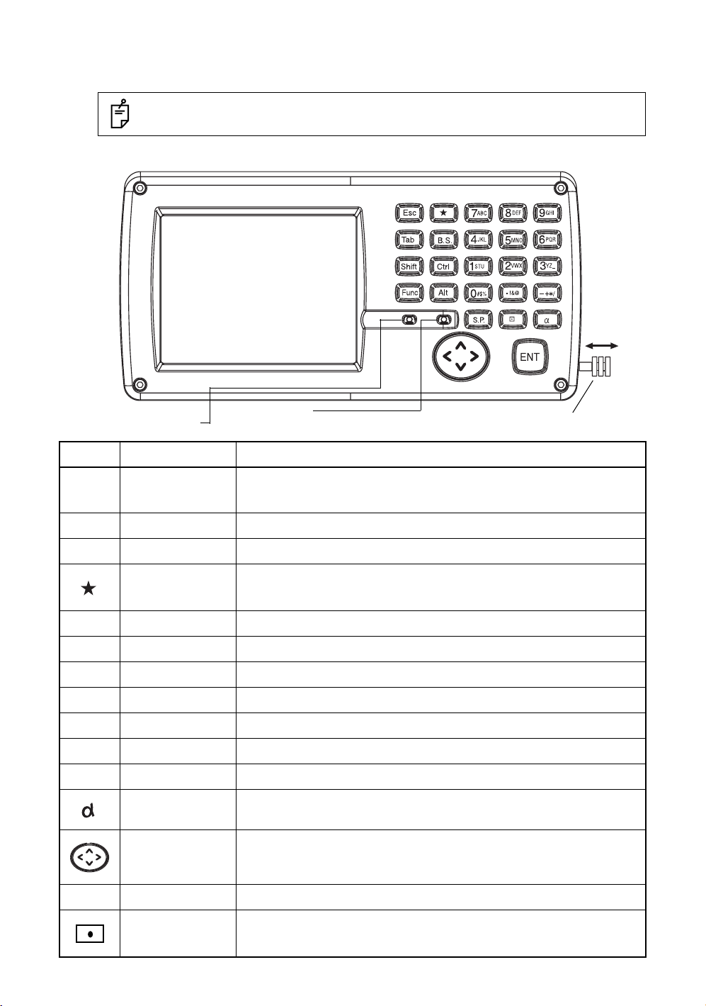
1.8 Operating Panel Key
To operate the keys on the screen, touch them lightly with either the accessor y stylus pen or your finger.
Use either the stylus pen or your finger.
Do not use a ballpoint pen or a pencil.
1.8.1 Operating Key
Light sensor
adjust backlight
KeysName of Key Function
0-9
A -/
Esc
ENT
Tab
B.S.
Shift
Ctrl
Alt
Func
Numeric key
Alpha key Entering Alphabets.
Escape key Returning to the previous mode or display.
Star key Star key mode is used for each presetting or displaying.
Enter key Press at the end of inputting values.
Tab key Moves the cursor to the right or downwards.
Back space key When inputting numbers or characters, return the cursor to the left.
Shift key Used with other keys. Refer to "1.2.5 Shortcut Keys".
Control key Used with other keys. Refer to "1.2.5 Shortcut Keys".
Alt key Used with other keys. Refer to "1.2.5 Shortcut Keys".
Function key Used with other keys. Refer to "1.2.5 Shortcut Keys".
Alphabet key Switches the keys to alphabet input mode.
Microphone
The stylus pen is stored beside the display.
Entering numerals.
Switching between wide-angle and telescopic images. (Keys [1] and [2])
Switching the cross-hairs. ON(black)/ON(white)/OFF (Key [9])
28
S.P.
Cursor
Space key Inputs a space.
Input panel key Displays the software input panel.
Moves the selected item or the cursor laterally and vertically.
Changes the image's magnification. ("Left" and "Right" keys)
Changes the image's brightness. ("Up" and "Down" keys)
Page 31

1 NOMENCLATURE AND FUNCTIONS
1.8.2 Turning OFF the Touch Panel Function
To wipe away tarnish and dirt on the touch panel while the power is turned ON, you can shut down the
touch panel function according to the following directions.
• Turning OFF the touch panel function.
1
Press the [ ] key while holding down the [Func] key.
The touch panel function will shut down.
• Turning ON the touch panel function.
1
Press the [Esc] key.
The touch panel function will resume operation.
1.9 Power OFF
When turning off the power, be sure to turn off the IS‘s power switch.
• Do not turn off the power by removing the battery.
Before removing the battery, press the power switch and confirm that the power is off.
• While using the external power source, do not turn off the IS with the switch on the external
power source.
If the above-mentioned operating procedure is not followed, then, the next time that power
is turned on, it will be necessary to reboot the IS.
• If you turn off the power in measuring mode, the instrument goes into the suspend mode,
then when you restart, the screen may be dark for a few seconds.
29
Page 32

1 NOMENCLATURE AND FUNCTIONS
1.10Operation Key(Touch panel)
Functions can be switched using the operation keys at the bottom of the screen for each of the following
modes.
Angle measuring mode Page 1
Distance measuring mode Page 1
Angle measuring mode Page 2
Distance measuring mode Page 2
Angle measuring mode Page 3
Coordinate measuring mode Page 1
30
Coordinate measuring mode Page 2
Page 33

Angle measuring mode
Page Display Function
1 NOMENCLATURE AND FUNCTIONS
0SET Angle of horizontal is set to 0° 00'00".
HOLD Holds the horizontal angle.
1
HSET Sets the horizontal angle by input value.
P1 The function of operation keys on next page (P2).
TILT
2
3
V/% Switches the vertical angle and percent grade.
R/L Switches R/L rotation of horizontal angle.
P2 The function of operation keys on next page (P3).
TURN Turns the instrument.
--- ---
--- ---
P3 The function of operation keys on next page (P1).
Sets the tilt function, ON/OFF.
If ON, the display shows tilt correction value.
Distance measuring mode
MEAS Distance measuring starts.
MODE Sets to the mode for Fine, Coarse or Coarse 10mm.
1
TURN Turns the instrument.
P1 The function of operation keys on next page (P2).
S.OTo be stake out measurement mode.
2
--- ---
--- ---
P2 The function of operation keys on next page (P1).
Coordinate measuring mode
MEAS Coordinate measuring starts.
MODE Sets to the mode for Fine, Coarse or Coarse 10mm.
1
TURN Turns the instrument.
P1 The function of operation keys on next page (P2).
R.HT Sets a Reflector Height by input value.
INSHT Sets an Instrument Height by input value.
2
OCC Sets an occupied point by input values.
P2 The function of operation keys on next page (P1).
31
Page 34

1 NOMENCLATURE AND FUNCTIONS
1.11Star Key Mode
Press the star( ) key to view the instrument options.
The following instrument options can be selected from the star key:
Auto-tracking icon
Auto-collimating icon
Auto-Inversion icon
Auto-tracking parameters set icon
Signal level icon
Electric circular level icon
Point guide icon or Tracking indicator icon
Focus icon
•
Prism / Non-prism / Non-prism long
switching icon
Laser pointer icon
Prism constant value,
Atmospheric correction icon
Reticle illumination icon
Electric circular level
Electric circular level can be displayed by graphic. This function is good for level the instrument
when the circular level is difficult to see directly.
32
Rotate the leveling screws while observing the display.
Page 35

1 NOMENCLATURE AND FUNCTIONS
Tracking Indicator
A man who is staying on line with the direction of IS series or automatic tracking status by emitted LED
light (orange color) from IS series.
Operation
Pressing [Tracking indicator icon] on the screen. The tracking indicator status will be changed according
to the type of auto tracking mode and its conditions. A man from the prism side can recognize the status
of instrument.
When angle measuring value turns stable during tracking still object, the tracking indicator changes
from quick continuous flashing to quick intermittent flashing. So you can decide from the sign of flashing
for recording data timing at one person surveying.
Tr acking indicator icon
•
OFF
ON
Meaning of Tracking Indicator ON or Flashing
Tr acking Indicator Status of instrument
Continuous ON Waiting or Searching status
Slow flashing Manual mode
Quick continuous flashing In case angle measuring value is instable during auto tracking mode.
Quick intermittent flashing In case angle measuring value is stable during auto tracking mode.
•
The function of the Tracking Indicator will be used as a guide to know the status of IS series
from the prism side. This is not a function to determine precise collimating for measuring.
•
he quality of its results will depend on the weather conditions and the use's eyesight.
•
Sometimes happens difficulty of seeing the tracking indicator because too much bright of
the beam for tracking.
Using Tracking Indicator mode will result shorter in reduced time out of the battery.
•
33
Page 36
1 NOMENCLATURE AND FUNCTIONS
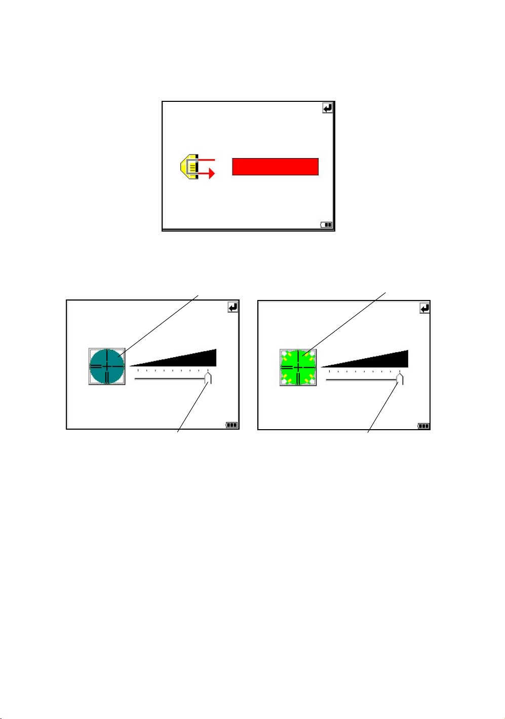
Signal mode
The light acceptance quantity level (Signal level) is displayed in this mode.
When reflected light from the prism is received, a buzzer sounds. This function is good for easy
collimation when the target is difficult to find.
The received return signal level is displayed with bar graph as follows.
Reticle illumination
Select the brightness by sliding [UP-DOWN] slider.
The brightness setting is stored in memory after power is turned off.
To turn on or off the reticle illumination, press the [reticle illumination] icon.
[OFF]
Reticle illumination icon
Reticle illumination icon
[ON]
34
[UP-DOWN] slider
[UP-DOWN] slider
•
•
Page 37

1 NOMENCLATURE AND FUNCTIONS
•
Laser Pointer ON/ON(blink)/OFF
The laser pointer assists with collimation by radiating visible laser light from the objective lens to the
target. The laser pointer can be used for the Prism, Non-prism and Non-prism long mode.
Laser aperture
•
Laser pointer will be OFF when auto-tracking or auto-collimation is ON.
•
The laser pointer indicates the approximate collimation position of the telescope. It does
not indicate the exact collimation position.
•
When the EDM is working, the laser pointer will blink.
•
You cannot see the laser pointer when looking through the telescope. Therefore, please
look directly, with the naked eye, at the point indicated by the laser pointer.
•
The distance to which the laser pointer can be used will vary with climatic conditions and
with the eyesight of the user.
•
When the laser pointer is used, the operating time of internal power source will become
short.
•
When the IS is used in the open air, in an urban area, etc., the laser pointer can be
stopped and distance measurement then conducted, making it possible to prevent the
laser light from hitting a third party.
•
Use the operation keys on the telescope eyepiece side for key operation. If you use the
operation keys on the objective lens side, an error will be displayed and the laser pointer
will not turn on. This prevents the laser beam from hitting the eyes of the operator.
•
Turn the auto-tracking ON/OFF
Press the Auto-tracking icon to start auto-tracking. See Section 3.1 “Automatic Tracking” .
•
Turn the auto-collimating ON/OFF
Press the Auto-collimating icon to start auto-collimating. See Section 3.2 “Automatic Collimation” .
•
Set the parameters for the auto-tracking
A proper setting for each parameter such as tracking pattern, tracking range, waiting time, tracking
speed and tracking sensitivity. See Section 3.4 “Setting Parameters for Auto-Tracking” .
•
Auto Inversion
Pressing the Auto-Inversion icon causes the instrument to reverse and turn the telescope and
instrument automatically. See Section 1.14 “Rotating Method” .
•
To stop auto rotating in case of emergency, press any keys except POWER key.
•
During auto rotation, do not disturb the instrument.(Stopping the rotation with a touch of
the hand). Such action may cause trouble or harm to instrument or operator.
•
Prism mode / non-prism mode / non-prism long mode
To switch the prism mode / non-prism mode / non-prism long mode, press the [Prism / Non-prism /
Non-prism long switching] icon. For more information, see Chapter 1.11.1 “Switching Measurement
Distance Modes”.
•
Prism constant value, Atmospherioc correction
Switch the prism constant value and atmospheric correction.
For more information, see Chapter 8 “SETTING THE PRISM / NON-PRISM CONSTANT
CORRECTION VALUE”, Chapter 9 “SETTING ATMOSPHERIC CORRECTION”.
•
Focus function
Switch the manual focus / assist-focus.
For more information, see Chapter 1.13 “Focus Function”.
The instrument is now in
manual focus mode.
The instrument is now in
assist focus mode.
35
Page 38

1 NOMENCLATURE AND FUNCTIONS
1.11.1Switching Measurement Distance Modes
Pressing the [Prism / Non-prism / Non-prism long] icon displays the following screen.
Each mode can be switched by using the buttons as shown below.
•
Setting Measurement distance range of ‘Non-prism long mode’
It is possible to measure long distance in the Non-prism Long mode. However, not all beams can be
thrown onto the target object since the diameters become bigger at long distance. In such a case,
the beam may also reach behind (or front) the object and the measurement may cause
inaccuracies. (See “Precautions for Use of Non-prism long mode” on page 78.)
If there is a certain distance between the object and its rear (or front), the correct measurement can
be obtainable by setting the measuring range.
Input range : 5m (17ft) - 1,800m (5,900ft)
Measuring range : from the distance you input to 200m backward
[e.g.]
When the distance to the target object is about 500m and when the distance to the wall behind the
object is about 700m, input 400m and measure between 400m and 600m. This will eliminate the
wall 700m ahead.
About 500m
400m
Measuring range
To set measurement distance range, see Section 4.3.3“Setting Measurement distance range of
Non-prism long mode” .
About 700m
600m
36
Page 39

1.11.2Setting by Using Star Key
[Example] : Switch on the laser pointer
1 NOMENCLATURE AND FUNCTIONS
1
Tu rn the power switch on.
2
Press the [ ] key.
3
Press the [Laser pointer] icon.
The laser pointer will be turned on.
37
Page 40

1 NOMENCLATURE AND FUNCTIONS
1.12Auto Power Off
To save battery power, the IS would automatically turn the power off (suspend) by itself
when it’s not in use. You can adjust the settings of this function.
• How to adjust the settings of auto power off function
1
Press the icon [Start]-[Settings][Control Panel]-[Power].
You can see the "Power Properties" screen on
Display.
2
Press the tab “Power Off”.
38
3
Press the time-menu down arrow to select the
auto power off time.
(Factory setting is '10 minutes' as default)
Page 41

1 NOMENCLATURE AND FUNCTIONS
4
Press the [OK] key on title bar.
After that "Power Properties" screen will close
automatically.
While on external power, the auto power off function can be enabled too.
To set this function, please check it 'ON' the "Enable suspend while on external power” on
the "Power Off " screen, and select the auto power off time.
(Factory setting is 'OFF' as default)
39
Page 42

1 NOMENCLATURE AND FUNCTIONS
1.13Focus Function
The focus is adjusted with the manual or assist-focusing.
1.13.1Manual Focus
Adjust the focus with focus jog / shuttle.
Manual focusing will take precedence over assist-focusing.
When using focus jog / shuttle during assist-focus mode, the assist-focus mode will end.
Focus shuttle : If you rotate the shuttle through large angles, the focus changes quickly.
Focus jog : The focus jog is used to focus more precisely. (fine focus)
If you rotate it through small angles, the focus changes slowly.
Focus shuttle
Focus jog
1.13.2 Assist Focus
The focus is always adjusted with software.
This is a convenient function for confirming the collimated image on display or when focusing on a
moving object.
When using focus jog / shuttle, the assist-focus mode will end.
Note:
• The assist focusing may be completed roughly when the contrast with the target and its
circumference is low. In this case, focus the target manually by turning the focusing jog/
shuttle.
• If there is an object that has higher contrast than a prism or a target near the horizontal hair
line in the field of view, the instrument may focus to that object.
• If a strong light comes into the eyepiece, the assist focusing may not be completed.
• Before operating, the diopter adjustment should be done by turning the diopter ring so that
the cross hairs are clearly observed.
• If parallax is created between the cross hairs and the target, focusing is incorrect. This
adversely affects precision in surveying. Eliminate the parallax by turning the focusing knob
or using the diopter adjustment.
40
Page 43

1.13.3 Setting Focus Function
[Example]
• Assist focus
The instrument is currently in manual
focus mode. Press the icon and mode will
switch to assist focus mode.
1 NOMENCLATURE AND FUNCTIONS
1
Tu rn the power switch on.
2
Press the [ ] key.
3
Use the sighting collimator to aim the target
roughly.
4
Press the [MF] icon.
The icon will change to [AF], and the
instrument will enter assist focus mode. Focus
adjustment is automatically done.
5
If you press the [AF] icon again, or turn the
focus jog/shuttle, the assist focus mode will
end.
The instrument is currently in assist focus
mode. Press the icon and mode will switch
to manual focus mode.
41
Page 44

1 NOMENCLATURE AND FUNCTIONS
1.14Rotating Method
This mark will appear while the
instrument is rotating automatically. *1)
1.14.1Rotating by H/V Shuttle and H/V Jog
H/V shuttle or H/V jog can be used to rotate the instrument manually. The shuttle movement or
displacement is proportional in speed and size of angle desired. A small, slow turn of the shuttle will
result in a slow small angle displaced. Likewise, a larger abrupt turn of the shuttle will result in a coarse
angle displacement. H/V jog can be used for accurate collimating of the target much like a standard
tangent screw.
*1)The mark will not appear.
1.14.2Auto Inversion
Pressing the Auto-Inversion icon in Star Key mode causes the instrument to reverse and turn the
telescope and instrument automatically.
• To stop auto rotating by auto inversion key in case of emergency, press any keys except POWER
key.
• During auto rotation, don't disturb the instrument.(Stopping the rotation with a touch of the hand).
Such action may cause trouble or harm to instrument or operator.
For further instructions, See Section 1.11 “Star Key Mode” .
1.14.3Rotating automatically to a required Horizontal and Vertical angle
In Standard Measurement Modes, the instrument can be rotated automatically by input a required
horizontal and/or vertical angle.
For further instructions, see Section 4.2.5 “Automatic Rotation to a Required Horizontal and Vertical
Absolute Angle” .
42
Page 45

1 NOMENCLATURE AND FUNCTIONS
1.15Using together with RC-3 Remote Control System
Using together with RC-3 Remote Control System makes it possible to optical communicate between
the instrument and remote controller RC-3, the prism side. This gives easy operation by one man
surveying in applying programs.
Also connecting data collector to remote controller, you can manage communication reciprocally
between the instrument and direct to data collector.
Turn-round function
You can turn the IS series round to the remote controller side easily by [Turn-round] key of the remote
controller. This function helps to increase one man surveying efficiency.
RC-3
See to 5 “PROGRAM MODE” and 6 “PARAMETERS SETTING MODE” for further information.
• Set the transmit channel same as the remote controller side.
43
Page 46

1 NOMENCLATURE AND FUNCTIONS
1.16Using connecting with Personal Computer (PC)
The auto-tracking function or auto collimating function makes easy remote control of the instrument
from PC. The followings are the main communication commands and explanations. How to
communicate or more informations of communication command, you can see the interface manual
which provided optionally.
Commands Action of IS series
Transmit
command
Mode setting
Tr ansmit command for measured data
Tr ansmit command for tracking mode
Tr ansmit command for battery level The battery level will be out put.
Tr ansmit command for coordinate of
instrument point
Tr ansmit command for additional
tracking information
Setting of angle measurement
Setting of distance measurement
Setting coordinate of instrument point Setting the coordinate of instrument point.
Setting the tracking parameter
Each measured data will be out put
according to the command type.
The status of Automatic Tracking mode
will be out put.
Setting coordinate of instrument point will
be out put.
Tr acking information will be added into the
output data in accordance with the setting
of the instrument.
Each selecting mode in horizontal angle
or angle measurement can be decided
according to the purpose of command.
Setting the measurement mode for
distance measurement.
Setting each tracking parameter
according to the command.
T.I. ON / OFF ON / OFF of Tracking indicator.
Rotating command Rotating of setting angle.
Action
• Please refer to the IS Series Interface Manual (sold separately) for details about connection
to the instrument.
Inversion Inversion movement.
Setting tracking mode
Setting from automatic tracking mode to
each command mode.
44
Page 47

1.17Using the USB Port
• Using ActiveSync
For Type mini B, refer to Chapter 2.9 “Active Sync”.
• Using a USB memory
1 NOMENCLATURE AND FUNCTIONS
USB
Type miniB (Active Sync)
Type A (USB Memory)
1
Open the USB connector cover.
2
Insert a USB memory into the Type A side.
3
Confirm that the USB memory has been recognized.
When using the USB port (mini B, Type A), do not rotate the instrument.
It will cause damage to the instrument, USB memory or F-25 cable.
45
Page 48

2 PREPARATION FOR MEASUREMENT
2 PREPARATION FOR MEASUREMENT
2.1 Power Connection
Obtain power from BT-65Q battery or an external battery.
• When using the BT-65Q, leave the power of the instrument switched ON.
External battery
• Selecting an external battery
When using an external battery, select the battery type, either “Li-ion” or “12V BATTERY.”
Regarding operating procedures, refer to Chapter 6 “PARAMETERS SETTING MODE” .
46
Page 49

2 PREPARATION FOR MEASUREMENT
2.2 Setting Instrument Up For Measurement
Mount the instrument to the tripod. Level and center the instrument precisely to insure the best
performance. Use tripods with a tripod screw of 5/8 in. diameter and 11 threads per inch, such as the
Type E TOPCON wide- frame wooden tripod.
Reference: Leveling and Centering the Instrument
1. Setting up the Tripod
First, extend the extension legs to suitable lengths
and tighten the screws on their midsections.
2. Attaching the Instrument on the Tripod
Head
Place the instrument carefully on the tripod head
and slide the instrument by loosening the tripod
screw. If the plumb bob is positioned right over the
center of the point, slightly tighten the tripod
screw.
3. Roughly Leveling the Instrument by Using
the Circular Level
1
Tu rn the leveling screws A and B to move the
bubble in the circular level. The bubble is now
located on a line perpendicular to a line
running through the centers of the two leveling
screws being adjusted.
Leveling screw C
Leveling
screw A
2
Tu rn the leveling screw C to bring the bubble
to the center of the circular level.
Leveling screw B
2
Rotate the instrument 90° (100g) around its
vertical axis and turn the remaining leveling
screw or C to center the bubble once more.
Leveling screw C
90
3
Repeat the procedures 1 and 2 for each 90°
(100g) rotation of the instrument and check
whether the bubble is correctly centered for all
four points.
5. Centering by Using the Optical Plummet
Telescope
Adjust the eyepiece of the optical plummet
telescope to your eyesight.
Slide the instrument by loosening the tripod
screw, place the point on the center mark, and
then tighten the tripod screw. Sliding the
instrument carefully not to rotate that allows you
to get the least dislocation of the bubble.
Point
Center mark
4. Centering by Using the Plate Level
1
Rotate the instrument horizontally by using
the Horizontal motion/clamp screw and place
the plate level parallel with the line connecting
leveling screws A and B, and then bring the
bubble to the center of the plate level by
turning leveling screws A and B.
Leveling
screw A
Leveling
screw B
6. Completely Leveling the Instrument
Leveling the instrument precisely in a similar way
to 4. Rotate the instrument and check to see that
the bubble is in the center of the plate level
regardless of telescope direction, then tighten the
tripod screw hard.
47
Page 50

2 PREPARATION FOR MEASUREMENT
2.3 Power Switch Key ON
1
Confirm the instrument is leveled.
Tu rn the power switch ON.
Progress bar will be displayed during reloading
the Operating System, after you turn the
instrument on at the first time or perform
hardware reset.
You will see the Desktop display of Windows CE
with “Standard Meas.” icon.
2
Press the “Standard Meas.” icon.
Main menu
The main menu will be displayed.
Battery Power Remaining Display
• Confirm the battery power remaining on the display. Replace with charged battery or charge when
battery level is low. see section 2.4“Battery Power Remaining Display” .
48
Page 51

2.4 Battery Power Remaining Display
Battery power remaining display indicates the power condition.
Measurement is possible.
2 PREPARATION FOR MEASUREMENT
Battery Power Remaining Display
The power is poor. The battery should be recharged or replaced
with a fully charged battery.
Measurement is impossible -- need to recharge or replaces the battery.
Note:
1) The battery operating time will vary depending on the environmental conditions such as
ambient temperature, charging time, the number of times of charging and discharging etc. It
is recommended for safety to charge the battery beforehand or to prepare spare full charged
batteries.
2) For general usage of the battery, see Chapter 11 “POWER SOURCE AND CHARGING” .
3) The battery power remaining display shows the power level regarding to the measurement
mode now operating.
The safety condition indicated by the battery power remaining display in the angle
measurement mode does not necessarily assure the battery‘s ability to be used in the
distance measurement mode.
It may happen that the mode change from the angle mode to the distance mode will stop the
operation because of insufficient battery power for the distance mode which consumes more
power than angle mode.
4) When the measurement mode is changed, it rarely may happen that the Battery Power
Remaining Display will decrease or increase two steps momentarily because of the
accuracy of the battery checking system is rough. It is not trouble with the instrument.
49
Page 52

2 PREPARATION FOR MEASUREMENT
2.5 Vertical and Horizontal Angle Tilt Correction
When the tilt sensors are activated, automatic correction of vertical and horizontal angle for
mislevelment is displayed.
To ensure a precise angle measurement, tilt sensors must be turned on. The display can also be used
to fine level the instrument. If the (TILT OVER) display appears the instrument is out of automatic
compensation range and must be leveled manually.
Zenith
Inclination of the standing
axis in the Y direction
Standing axis
Zenith
Inclination of the standing
axis in the X direction
Standing axis
Horizontal
• IS compensates both the vertical angle and the horizontal angle readings due to inclination of the
standing axis in the X and Y directions.
• For more information about dual axis compensation, see Chapter 19 “APPENDIX” .
When the instrument is out of compensation. (TILT OVER)
Tr unnion axis
Standing Axis in the X direction
out of range
• The display of Vertical or Horizontal angle is unstable when instrument is on an unstable stage or a
windy day. You can turn off the auto tilt correction function of V/H angle in this case. To set TILT
correction mode ON/OFF, refer to section 2.5.1 “Setting Tilt Correction by Operation Key”or Chapter
6 “PARAMETERS SETTING MODE”
Standing Axis in the Y direction
out of range
Standing Axis in the X and Y
directions out of range
50
Page 53

2.5.1 Setting Tilt Correction by Operation Key
[Example] Setting Tilt OFF
1
2
2 PREPARATION FOR MEASUREMENT
Press the [P1] key to get the page 2.
Press the [TILT] key.
Current setting is displayed.
3
Press [OFF] key.
4
Press [EXIT] key.
The display returns previous mode.
• The setting performed here will be interlocked with setting in Chapter 6 “PARAMETERS SETTING
MODE”
2.5.2 Correction of a Tilt Sensor setting error
An error in setting up the Tilt Sensor can be automatically corrected with the Self Checking function.
See Chapter 7.6 “Self Checking Mode” .
51
Page 54

2 PREPARATION FOR MEASUREMENT
2.6 Compensation of Systematic Error of Instrument
1) Error of vertical axis (X,Y tilt sensor offset)
2) Collimation error
3) Error of vertical angle 0 datum
4) Error of horizontal axis
The above mentioned errors can be compensated by software, which calculated internally
according to each compensation value.
Also these errors can be compensated by software collimating one side of the telescope that is
carried out to delete the error by turning in normal and reverse both sides of telescope so far.
• To adjust or reset the above compensation value, see Chapter 7 “CHECK AND ADJUSTMENT” .
• Enable you to stop this function, see Chapter 6 “PARAMETERS SETTING MODE” or Chapter 7
“CHECK AND ADJUSTMENT”
52
Page 55

2 PREPARATION FOR MEASUREMENT
2.7 How to Enter Numerals and Alphabet Letters
This instrument supports two ways to enter numerals and alphabet letters.
One is by physical(hardware) keyboard that is similar to cellular phone method.
Three alphabet characters are assigned to one numeral key.
The other is by using the software input panel.
Press the [ ] key or press keyboard icon on the task bar will invoke the software input panel.
• [Example] : Enter “job_104” as the New Folder name by physical(hardware) keyboard.
Make sure the mode is Windows CE desktop screen.
1
Press and hold the background of Desktop for
two seconds.
You can see the "Pull down menu" on Display.
2
Select “New Folder”.
You can see the "New Folder" waiting a new
name inputting on Display.
53
Page 56

2 PREPARATION FOR MEASUREMENT
Alphabet letter mode indicator
3
Press the [ ] key to be entering alphabet
letter mode.
Alphabet letter mode indicator will be appeared
on the task bar.
4
Enter Alphabets.
Input 'j',
Press [4](JKL)key. then the sub window
featuring 'j' character will appear on the display
which indicate a entering character.
54
m
n
o
Then ‘j’ will be displayed.
5
Input 'o',
Press [5](MNO),[5],[5].
The character in the sub window will be altered
'm', 'n', 'o'.
Then ‘o’ will be appended after ‘j’.
6
Input ‘b’,
Press [7](ABC), [7].The character in the sub
window will be altered 'a', 'b'.
Then ‘b’ will be appended after ‘jo’.
7
Input ‘_’,
Press [3](YZ_), [3], [3].
The character in the sub window will be altered
'y', 'z', ‘_’.
Then ‘_’ will be appended after ‘job’.
Page 57

2 PREPARATION FOR MEASUREMENT
8
Press the [ ] key to be returning numeric
mode.
Alphabet letter mode indicator will be
disappeared on the task bar.
9
Input ‘104’,
Press [1], [0], [4].
Then ‘104’ will be appended after ‘job_’.
10
Press the [ENT] key.
In alphabet letter mode, [Shift] + [0-9,.-] keys perform uppercase character.
55
Page 58

2 PREPARATION FOR MEASUREMENT
• Invoke the software input panel.
1
Press the [ ] key or press keyboard icon on
the task bar and select “Keyboard”
You can see the software input panel on display.
You can input data as if you were typing on your
PC keyboard.
To change the keyboard:
Press the [CAP] key or the [au] key.
2
To hide the software input panel, press the [ ]
key or press keyboard icon on the task bar and
select “Hide Input Panel”.
56
Page 59

2.8 Data Memory Card
• How to insert a data memory card(CF card)
2 PREPARATION FOR MEASUREMENT
Card cover
Card cover
lever
1
Push up the card cover lever to open the card cover.
2
Insert a data memory card.
Please make sure you have the front and back of the CF cards facing correctly when inserting into
the card slot.
If you forcibly insert the card incorrectly, the pin at the card slot may be damaged and cause a
breakdown.
Card guide
Data memory
card
Front of the card
Please insert straight up into the card slot.
If you forcibly insert the card at an angle, the pin at the card slot may be damaged and cause a
breakdown.
3
Close the card cover.
• How to extract a data memory card
1
Push up the card cover lever to open the card cover.
2
Pull down the card guide.
Note: Hold the card with your hand to protect the card against falling.
3
Extract the card.
4
Close the card cover.
57
Page 60
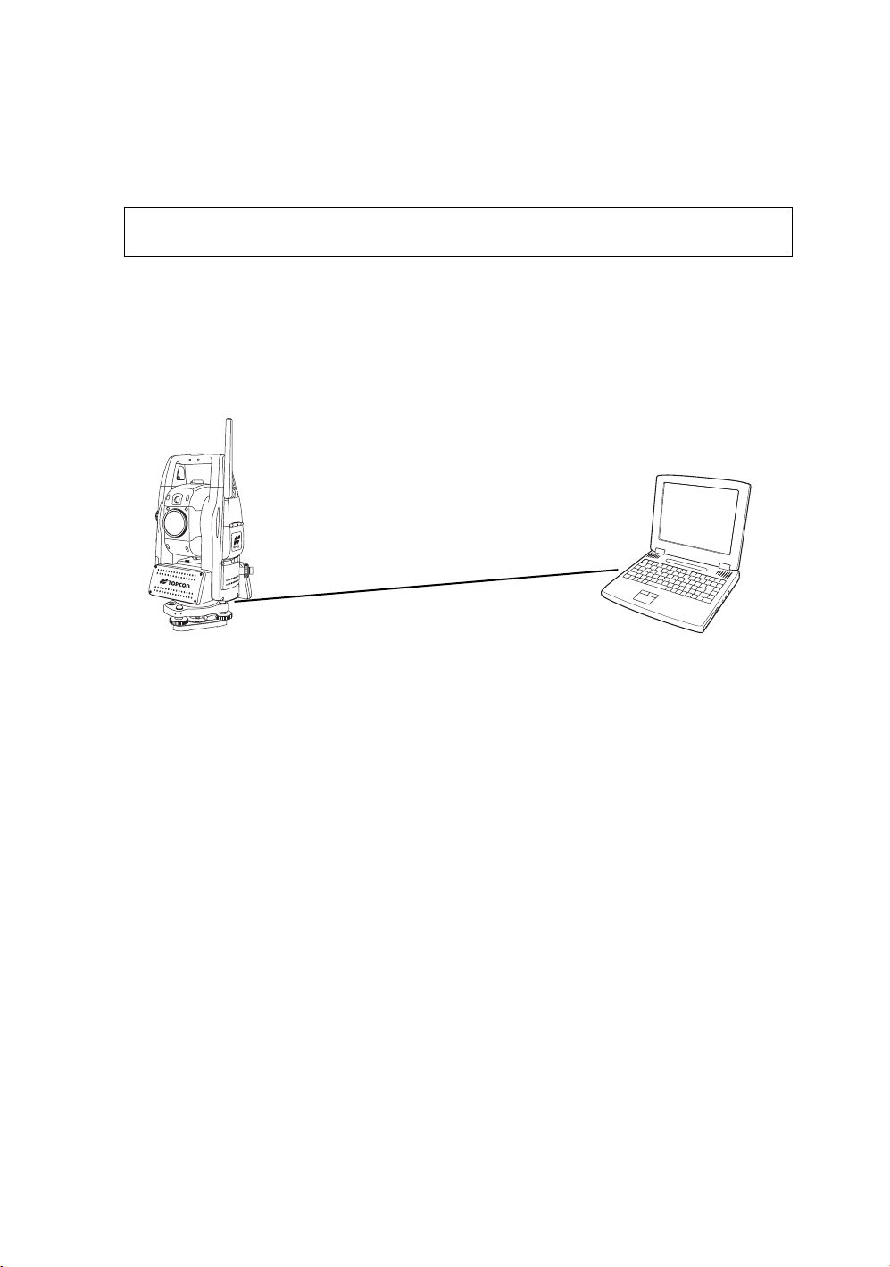
2 PREPARATION FOR MEASUREMENT
2.9 Active Sync
Microsoft ActiveSync is the data synchronization software:
It synchronizes data between Windows CE devices (such as the IS) and PCs.
Using ActiveSync, the IS can exchange data to a PC via USB cable.
To establish a connection between the instrument and your PC, you first need to install ActiveSync in
your PC.
For downloading ActiveSync, access the following website.
http://www.microsoft.com/windowsmobile/
2.9.1 Getting Connected
1
Install ActiveSync in your PC (if it is not already installed).
2
Connect the instrument to your PC with an interface cable F-25 as shown below.
IS
PC
Interface(USB) cable F-25
USB Port (mini B)
3
The instrument will give the prompt, “Conneting to Host”.
4
The PC will prompt you to set up a partnership or set up as a guest.
5
Select the [NO] key to setting up as a guest.
6
Press the [Next] key.
Once a connection has been established, the ActiveSync window will appear on your PC.
7
Click the [Explorer] icon. You will then see the IS file structure.
2.10Confirming the Bluetooth
®
Device Address and Setting the PIN
USB Port (A)
code
You can confirm the Bluetooth® address and set the PIN code.
Refer to Chapter 6 “PARAMETERS SETTING MODE” , Chapter 6.1.2 “Communication” .
To communicate between the instrument and some other Bluetooth-enabled instrument, it is necessary
to make the PIN codes of both instruments identical.
If two PIN codes don’t coincide, the two instrument cannot communicate each other.
For setting the PIN code of other Bluetooth-enabled instrument, see the instrument’s instruction
manual.
58
Page 61

2 PREPARATION FOR MEASUREMENT
2.11Wireless LAN Function ON/OFF
It is possible to connect to a network via wireless if Wireless LAN function is used.
Follow the procedure below to turn on the Wireless LAN function.
1
Tap on [Start]-->[Settings]-->[Control Panel]-->[WLan Power] icon.
2
On the [Wireless LAN Power] screen, tap on the [POWER ON] button.
2.12Inclination of Prism and Measuring Error
For the best results, aim or point prisms in the direction of the IS series so that maximum signal can be
returned to the instrument. Sighting prism obliquely because of inclined settings, may result in
measuring errors. These errors will be proportional to the misalignment as showing in following graphs.
The more misalignment of the prism, the more error in measurement.
Measured data can be different according to the prism constant value. This can occur when a prism is
moving. Pin-pole prism set L1 (for one-person surveying) and pin-pole prism holder L1 (for fixed point
observation) are designed to minimize measuring error in such case. Make the best use of them. In
case you are forced to use the normal prism in inclined state because there is no other way possible,
we recommend to use switching holder, prism constant value (0 or 30mm), and set to 30mm
(Compensation value of -30mm).
Prism constant value : 0mm
Prism
Inclined angle
Measuring
point
Prism constant value : 30mm
Inclined angle
Instrument
point
59
Page 62

2 PREPARATION FOR MEASUREMENT
• Prism type-2 (Normal prism)
Distance Measuring error
6
5
4
Increasing
distance
range
( mm )
3
C=0
2
1
0
-1
0
10
20
Inclined angle (degree)
• Prism type - 3 or 5 (Prism unit A2/A3/A6)
Distance Measuring error
C=30
C=40
Angle error
range
( mm )
30
22
16
12
8
-2
Angle measuring error
C=0
C=30
4
C=40
0
0
10
20
30
Inclined angle (degree)
Angle measuring error
Increasing
distance
range
Angle error
range
( mm )
( mm)
Inclined angle (degree)
Inclined angle (degree)
(Example)
In case Prism constant value (C) = 0mm, Prism inclination = 20°, Measuring distance = 100m by Prism
type-2 :
• Distance error is :
From the graph prism type-2, the distance error shows in increasing range quantity 2.5mm along
curved line of C=0 when prism inclination is 20°.
• Angle error is :
From the graph prism type-2, along curved line of C=0 with prism inclination of 20°, find angle error
quantity (14.2mm) and calculate angle error by the following formula.
--------------------------------------------------------------
60
--------------------------
″
Page 63

3 AUTOMATIC TRACKING / AUTOMATIC COLLIMATION
3AUTOMATIC TRACKING / AUTOMATIC COLLIMATION
WARNING
Cause eye injury or blindness.
Do not stare into beam.
CAUTION
Let the laser beam reach the aimed object or the target without anybody else in the laser beam path. In
case you operate laser beam open, avoid radiating laser beam to the height of man's head. It is quite
possible for the beam to enter into one's eyes, and it is possible to lose visual sight temporarily, and lose
one's caution and awareness of other dangers - avoid glaring beam.
•
•
61
Page 64

3 AUTOMATIC TRACKING / AUTOMATIC COLLIMATION
3.1 Automatic Tracking
The instrument will measure the moving target(prism) in automatic tracking mode.
It is possible to perform auto-tracking only in prism mode.
When switched to the automatic tracking mode, it becomes prism mode from Non-prism mode/Nonprism long mode automatically. Moreover, after the end of an automatic tracking does not return to
Non-prism mode/Non-prism long mode.
The prism should be stable when beginning auto-tracking. Moreover, when the prism is locked from
the search, it is similar.
The Coarse 10mm mode must be used when measuring distance continuously for the moving
prism. In other modes, it is impossible to measure the distance continuously.
Change to the Fine mode when measuring the distance with high accuracy for the stationary prism.
1
Roughly collimate the target prism using V/H
jog/shuttle.
(Refer to Section 3.3 “Range of Laser for Autotracking and Auto-collimating”.)
2
Press the star [ ] key to set the star key
mode.
3
Press the Auto-tracking icon. The mode will be
automatic tracking mode.
The instrument searches the prism and tracks
it automatically.
62
4
Choose measuring modes by pressing the
operation keys.
Measuring starts.
When you wish to cancel the automatic tracking
mode, press the star [ ] again, and then
press the Auto-tracking icon.
•
•
•
•
•
Page 65

3 AUTOMATIC TRACKING / AUTOMATIC COLLIMATION
If the target prism is lost during auto tracking status, the instrument will automatically change to Waiting
status. If the target is found during Waiting status, tracking resumes, and if not, status changes to
Searching status. The instrument and telescope rotate to search the target prism. When the target prism
is found, tracking will resume.
Star key
mode
Automatic tracking
Normal
Tracking status
mode
The target prism is lost
Waiting status
The target prism is not found
for some time
Searching status
•
The following symbol marks are indicated at the upper side of the display.
In each status, laser beam is emitting.
Tr acking status
Waiting status
The target prism
is found
Searching status
Auto tracking status can sometimes be unstable for a few seconds after the optical path is disturbed.
If the stationary target prism center is not collimated correctly, you should adjust optical axis for autotracking. Refer to Section 7.2.3 “Inspection and Adjustment of Optic Axis for Auto -Tracking”.
Under the bad weather condition, for example, when the heat shimmer is generated in a great degree or
when visibility is poor, tracking may be unstable or the instrument may not track the prism center.
Use the operation keys on the telescope eyepiece side for key operation. If you use the
operation keys on the objective lens side, an error will be displayed and auto-tracking will
not start.
•
•
•
•
•
63
Page 66

3 AUTOMATIC TRACKING / AUTOMATIC COLLIMATION
3.2 Automatic Collimation
The function enables the instrument to search and collimate automatically the center of the prism when
the telescopic is aimed at a prism roughly. (in the range of approx. ±5°)
Use this mode for the object which is stable.
You can select Fine or Course mode for the distance measurement in auto-collimation.
1
Collimate the target prism roughly using V/H
jog/shuttle.
2
Press the Auto-collimating icon.
The automatic collimation mode is set. The
instrument searches the prism and, when it is
found, “ Pi ” is heard.
The automatic collimation is completed.
3
Choose measuring modes by pressing the
operation keys.
Measuring starts.
Sample: Horizontal distance measuring
It is possible to use the auto collimation during
the star key mode.
In case the instrument could not find the prism during auto-collimating, the instrument returns to normal
mode after displaying the mark as follows.
If any key is pressed during auto-collimating, the auto-collimating mode is ended and the instrument
returns to normal mode.
After auto-collimating is finished, the instrument does not track the prism even if the prism is moved.
The auto-collimating can not be done correctly in the time of shaking prism, or under bad weather
condition for example, when the heat shimmer is generated in a great degree or when visibility is poor.
The above caution mark will be displayed after 10 seconds and the auto-collimating will be finished.
64
Use the operation keys on the telescope eyepiece side for key operation. If you use the
operation keys on the objective lens side, an error will be displayed and auto-collimation
will not start.
•
•
•
•
•
•
•
Page 67

3 AUTOMATIC TRACKING / AUTOMATIC COLLIMATION
3.3 Range of Laser for Auto-tracking and Auto-collimating
The range of laser at the long distance is within ±30' as shown below. So you had better collimate the
prism so that the prism may be located within this range of laser in the first step. As for it, rapid
automatic collimating and automatic tracking becomes possible. If the target prism is out of this range,
time for searching mode will be necessary to take a longer time for automatic collimating/tracking.
Field of view of telescope
about ±30'
Range of tracking laser beam
about ±30'
The range of the laser beam for auto-tracking in a short distance is almost the same as a telescopic
filed of view. Therefore, quick starting of auto-tracking and auto-collimating are possible if the prism is
contained in the telescopic field of view.
65
Page 68

3 AUTOMATIC TRACKING / AUTOMATIC COLLIMATION
3.4 Setting Parameters for Auto-Tracking
A proper setting for each parameter are necessary for custom use.
The setting of the parameters can be done in the star key mode.
The setting here will be stored in the memory after the power is turned OFF.
3.4.1 Setting Items
Items
SEARCH
PATTERN
SEARCH
RANGE
WAIT TIME 0:00 to1:00:00
TRACKING
SPEED
REFLECTOR
TYPE
PREDICTION
CTRL TIME
Selecting item Contents
PATTERN 1 The search range is the area to searched for the prism by rotating
PATTERN 2
V:0° to 90°
H:0° to180°
(1sec. step)
HOLD
SURVEY Select SURVEY usually.
MACHINE
CONTROL
PRISM The type of the reflector can be selected.
REFLECTOR
TAPE
0.5sec./ 1sec. /
2sec. /3sec. / 4sec
/ 5sec.
the telescope and body in searching.
The search range is the area to searched for the prism by rotating
the telescope and body in searching. The SEARCH range is
decided from the point where the prism lost, and the values will be
set to plus and minus directions in horizontal and vertical. Also it is
enable to set each search pattern separately.
The time the prism is lost before IS series starts the searching. If the
mode is set to [HOLD], mode will not change to searching.
After the instrument loses a prism, the time (prediction operation
time) for the instrument to continue moving operation can be set up.
1) Search Patterns
The search pattern is the rotating method of telescope and instrument to find the target prism in search
mode. Search pattern includes the following 2 ways that can be selected.
PATTERN 1
PATTERN 2
66
This pattern can be selected to search the prism at the point where the prism is lost.
Instrument searches in up down direction gradually from the point where the prism is lost.
The searching is arranged to 2 times until the prism is found.
The auto tracking mode changes to manual mode when the reflector could not found out
within 2 times searching, and returns to the point where the reflector is lost.
This pattern can be selected to search for the prism. The search pattern tries to locate the
prism in a very short time.
The searching is arranged to 2 times until the reflector is found.
The auto tracking mode changes to manual mode when the reflector could not found out
within 2 times searching, and returns to the point where the reflector is lost.
Things like heat haze might interfere with the tracking system in the long distance, near limit of auto
tracking range, in search mode.
Reaction by rotating of instrument in search mode is serious. Be sure of each connection part of the
tribrach or tripod are firmly.
•
•
Page 69

3 AUTOMATIC TRACKING / AUTOMATIC COLLIMATION
2) Search Range
The search range is the area to searched for the prism by rotating the telescope and body in Searching.
The Search range is decided from the point where the prism lost, and the values will be set to plus and
minus directions in horizontal and vertical.
Select search pattern first, and set the search range to the selected search pattern. Also it is enable to
set each search pattern separately.
[Example] SEARCH RANGE : 10
Search range
Point where prism lost
Setting Search range requires consideration. The items to think about: optical path interrupted by other
objects; collimated point from IS series to prism is shifted after Turning and Searching Command;
possible other prisms, targets, or other objects to interfere with tracking the desired prism; and many
other examples all play a role in determining the search range.
Note: This search range is only for auto-tracking function. The search range of auto-collimating is fixed
as ±5
°
in both directions horizontal and vertical.
in horizontal, 5° in vertical
+5°
10°
-5°
-10° +10°
20°
3) Wait Time
The time the prism is lost before IS series starts the searching. Setting time is 1second step maximum
60 minutes.
If the mode is set to [HOLD], mode will not change to searching.
4) Tracking Speed
Choose the mode of “Survey” or “Machine Control” according to the purpose of measurement.
•
In case requiring auto aiming in high accuracy to the prism which is still.
•
SURVEY
Suitable for fixed point observation, management of landslides, surveying
displacement of dam.
•
When beginning auto-tracking, the instrument needs to collimate stable prism.
•
MACHINE
CONTROL
Note: If the Machine Control mode is chosen, the IS may incorrect-track the headlight of a car etc.
temporarily.
Suitable for controlling of construction machinery or real time surveying of variety
traveling objects.
•
When beginning auto-tracking, the instrument can track a prism, even if the prism is
moving.
5) Reflector type
You can choose a reflector type according to reflective objects such as Prism-2 or reflector tape.
This setting will reduce incorrect tracking.
67
°
Page 70

3 AUTOMATIC TRACKING / AUTOMATIC COLLIMATION
6) Prediction operating time
After the instrument loses a prism, the time (prediction operation time) for the instrument to continue
moving operation can be set up.
During auto tracking operation, when auto tracking axis between the instrument and a prism is
intercepted by a tree etc., the moving is continued supposing a motion (prediction) of the prism till then.
It is effective in auto tracking operation after the prism is intercepted with the obstacle by this function.
When an obstacle is large, the prediction operation time should be set up long.
Moreover, when you want to terminate auto tracking operation immediately at the point which missed
the prism, and to be changed into a search state. Prediction operation time should be set up short.
Settable time: 0.5sec, 1sec, 2sec, 3sec, 4sec, 5sec
3.4.2 How to set the parameters
Sample setting: Reflector Type [Prism], Prediction Ctrl Time [5 sec], Track Speed [Survey]
1
Press the star [ ] key to set the star key
mode.
2
Press the [Auto-tracking parameters set] icon.
3
Press the [Track Setting] key.
4
Select the Reflector Type.
5
Select the Prediction Ctrl Time.
6
Select the Track Speed.
7
Press the Enter key.
68
Page 71

4 STANDARD MEASUREMENT MODE
4STANDARD MEASUREMENT MODE
STANDARD MEASUREMENT MODE
Angle measurement, Distance measurement, Coordinate measurement .
Press the [MEAS] icon.
4.1 Screen Displays
In the standard measurement mode, the collimation screen is displayed on the display device except
during collimation with the telescope.
The images include a telescopic image and a wide-angle image.
• Telescopic image : An image similar to that obtained by collimation with the telescope is displayed.
• Wide-angle image : An image with a wide-angle is displayed.
4.1.1 Switching between Telescopic Image and Wide-Angle Image
When numeric key [1] is pressed, a telescopic
image appears.
When numeric key [2] is pressed, a wide-angle
image appears.
See section 1.8.1“Operating Key”.
It is also possible to switch between a
telescopic image and a wide-angle image by
tapping the screen.
* The focus of telescopic images is adjusted
with the telescope focusing knob.
Displays the current mode.
TELE: Telescopic image
WIDE: Wide-angle image
69
Page 72

4 STANDARD MEASUREMENT MODE
4.1.2 Changing the Image's Magnification
Displays the current magnification.
There are 4 magnifications: 0.5, 1.0, 2.0, 4.0 and 8.0
4.1.3 Adjusting the Image's Brightness
When the [←] cursor key is pressed,
magnification decreases.
When the [
magnification increases.
When the [
the brightness becomes brighter.
When the [
the brightness becomes darker.
→
] cursor key is pressed,
↑
] cursor key is pressed,
↓
] cursor key is pressed,
* Adjust the brightness to make the image
clearer.
70
Page 73
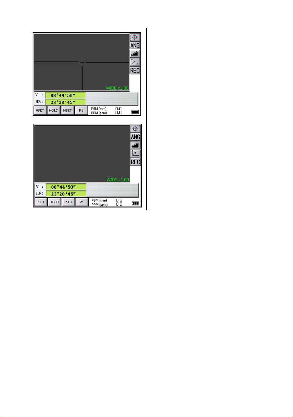
4.1.4 Switching the Cross-Hairs On and Off
4 STANDARD MEASUREMENT MODE
Each time numeric key [9] is pressed,
the cross-hairs appear or disappear from the
image.
Each time the [9] key is pressed, the crosshairs on the screen image will change.
(Black/White/OFF)
71
Page 74

4 STANDARD MEASUREMENT MODE
4.2 Angle Measurement
4.2.1 Measuring Horizontal Angle Right and Vertical Angle
Make sure the mode is in angle measurement
1
Collimate the 1st target (A).
2
Set horizontal angle of target (A) at 0° 00' 00".
Press the [0SET] key and the [YES] key.
3
Collimate the 2nd target (B).
The required H/V angle to target B will be
displayed.
72
Page 75

4.2.2 Switching Horizontal Angle Right/Left
Make sure the mode is angle measurement.
Every time pressing the [R/L] key is pressed, HR/HL mode switches.
.
Reference : How to Collimate
1
Point the telescope toward the light. Turn the diopter ring and adjust the diopter so that the cross
hairs are clearly observed.
(Turn the diopter ring toward you first and then backward to focus.)
2
Aim the target at the peak of the triangle mark of the sighting collimator. Allow a certain space
between the sighting collimator and yourself for collimating.
3
Focus the target with the assist focus
key or focus jog/shuttle.
4 STANDARD MEASUREMENT MODE
•
1
Press the [P1] key to get on the page 2.
2
Press the [R/L] key.
The mode Horizontal angle Right(HR) switches
to angle Left(HL) mode.
3
Measure the target in the same manner as HR
mode.
If parallax is created between the cross
hairs and the target when viewing
vertically or horizontally while looking
into the telescope, focusing is incorrect
or diopter adjustment is poor.
This adversely affects precision in
measurement or survey.
Eliminate the parallax by carefully
focusing and using diopter adjustment.
For more information about assist focus function, see section 1.13“Focus Function” .
Telescope eyepiece (Diopter ring)
73
Page 76

4 STANDARD MEASUREMENT MODE
4.2.3 Measuring from the Required Horizontal Angle
1) Setting by Holding the Angle
Make sure the mode is angle measurement .
1
2
3
4
*1)To return to the previous mode, press the [NO] key.
2) Setting a Horizontal Angle from the Keys
Make sure the mode is angle measurement.
Set the required horizontal angle, using
Horizontal jog/shuttle.
Example : 90°20'30"
Press the [HOLD] key.
Collimate the target.*1)
Press the [YES] key to finish holding the
horizontal angle.
The display turns back to normal angle
measurement mode.
70.2030
1
Collimate the target.
2
Press the [HSET] key.
3
Input the required horizontal angle.
For example:70
Input 70.2030
4
Press the [SET] key. *1)
When completed, normal measuring from the
required Horizontal angle is possible.
°
20'30"
*1)With wrong input value(for example 70'), setting will not be completed. Input again from step
74
3
.
Page 77

4.2.4 Vertical Angle Percent Grade(%) Mode
Make sure the mode is angle measurement .
1
Press the [P1] key to get on the page 2.
2
Press the [V/%] key. *1)
*1) Every time pressing the [V/%] key, the display mode switches.
4 STANDARD MEASUREMENT MODE
75
Page 78

4 STANDARD MEASUREMENT MODE
4.2.5 Automatic Rotation to a Required Horizontal and Vertical Absolute Angle
The IS series can be rotated to a required horizontal and vertical absolute angle by direct key input.
Example: Both vertical and horizontal angle
1
At angle measuring mode (Page 3), press the
[TURN] key.
2
Select item to rotate.
[Example]: V, H ANGLE
3
Input angle.
For example:50
Input 50.2030
4
Press the [SET] key.
Rotation will begin.
After completing the rotation, it will return to the
previous mode.
*1) Setting range for rotation is ;
0
°
00' 00" ≤ V < +360
0
°
00' 00" ≤ HR < +360
*2) Press any key except power key to stop rotating in emergency during operation.
*3) You can select a accuracy of the actual stopping angular positions. Refer to Chapter 6 “PARAMETERS
SETTING MODE” .
°
00' 00"
°
00' 00"
°
20'30"
76
Page 79

4 STANDARD MEASUREMENT MODE
4.3 Distance Measurement
Note: Those distance shorter than 1m and 400m or more will not be displayed in Non-prism
mode.
Those distance shorter than 4.5m and 2010m or more will not be displayed in Nonprism long mode.
Prism mode and Non-prism mode
In IS series, the distance measurement will be done using invisible pulse laser beam emitted from pulse
laser diode. You can select measurement mode between Prism mode which collimating a prism and
Non-prism mode, Non-prism long mode that is collimating a target object except prism.
•
For measurement with a prism, be sure to measure with the prism mode. If you measure with the
non-prism mode and non-prism long mode accuracy cannot be guaranteed.
•
Non-prism mode and non-prism long mode enable all distance measurements such Distance
measurement, Coordinate measurement, Offset measurement and Layout.
•
To s witch over Prism mode to Non-prism mode or Non-prism long mode, press the [NP/P] operation
key in each measurement display. [NP] of Non-prism mode indicator will be shown at the right
corner of the display in Non-prism mode measurement. (or [LNP] of Non-prism long mode indicator
will be shown.)
Changing mode shall be done before measurement.
•
Example
•
•
•
Distance measurement mode
Non-prism mode indicator
When using a reflection sheet, measure with the prism mode.
It is possible to set Non-prism mode or Non-prism long mode for distance measurement during the
power on time.
If happened collimating the near distance prism in Non-prism mode or Non-prism long mode,
measurement will not be done because of too much light.
Coordinate measurement mode
77
Page 80

4 STANDARD MEASUREMENT MODE
•
Precautions for Use of Non-prism long mode
IS series made non-prism measurement possible to reach the distance that had never been achieved
before.
In the non-prism long mode, the following attentions need to be paid because the farther the target
object be, the weaker the reflection from the target and the larger the beam diameter become.
1) Measurement Time
In the non-prism long mode, the measuring time largely depends on a distance to the target object
and the color (or reflectance) of the object. Especially when the measurement distance is far, or
when the reflectance of the measured surface is low, measuring time will become longer.
2) Beam Diameter
Beam diameter becomes large in the long distance. Try to bring as much beam as possible to the
measured surface.
If the beam is not lased rightly as in the cases below, may cause incorrect measurement.
In such cases, collimate the position where the beam is not fallen besides the measured surface,
set measurement distance range ( Chapter 4.3.3 “Setting Measurement distance range of Nonprism long mode” .).
(e.g.1) the beam also reaches the wall either before or behind the object
(e.g.2) the beam reaches the wall behind due to the size of the object
(e.g.3) the beam is thrown on the ground before the object
3) Cutoff during Measurement
While in the Non-prism long mode, you had better use the instrument in the place where the light
path may not be cut off by cars or people. You may not be able to collect accurate figures if it is often
cut off.
4) Re-measuring
When the reflectance of the measured surface drastically changes as in the case of looking quickly
from the white object to the black object, or when the distance to the object changes a lot, you may
face a temporary suspension. If you cannot measure even after a while, press [MEAS] or [MODE]
key to restart measurement.
78
Page 81

4 STANDARD MEASUREMENT MODE
4.3.1 Setting of the Atmospheric Correction
When setting the atmospheric correction, obtain the correction value by measuring the temperature
and pressure.
Setting the atmospheric correction, see Chapter 9 “SETTING ATMOSPHERIC CORRECTION” .
4.3.2 Setting of the Correction for Prism Constant
Topcoat’s prism constant value is 0. Set correction for prism at 0. If the prism is of another manufacture,
the appropriate constant shall be set beforehand.
Setting the prism / non-prism constant value, see Chapter 8 “SETTING THE PRISM / NON-PRISM
CONSTANT CORRECTION VALUE” . The setting value is kept in the memory even after power is off.
Note: Confirm that Non-prism correction value is set at zero before measurement target such
as a wall in Non-prism mode.
4.3.3 Setting Measurement distance range of Non-prism long mode
To set measurement distance range, carry out the following operating procedure.
1
Press the star [ ] key.
2
Press the [NP/P] key.
3
Press the [LNP DIST RANGE] key.
79
Page 82

4 STANDARD MEASUREMENT MODE
4
Input the distance range by pressing the
numeric key. *1)
Example:10m
[ENTER] key
5
Press the [ENTER] key.
The display returns to the star key mode.
*1) Input range: 5 m - 1,800 m (17 ft. - 5,900 ft.)
80
Page 83

4 STANDARD MEASUREMENT MODE
4.3.4 Distance Measurement (Continuous Measurement)
Make sure the mode displays angle measurement
.
1
Collimate the center of prism.
2
Press the [ ] key.
*1),*2)
[Example]:
Horizontal distance / Relative elevation mode
The result are shown.*3) ~ *7)
*1), *2)
*1)The following characters will be shown on the 4th line right hand of the display to represent measurement
mode.
F=Fine; C=Coarse1mm; c=Coarse10mm; R=Continuous (Repeat); S=Single; N=N-times
*2)When EDM is working, the " *" mark appears in the display.
*3)The result is shown with buzzer sound.
*4)Measurement may repeat automatically if the result is affected by shimmer etc..
*5)To change single measuring, press the [MEAS] key.
*6)To change SD/HD&VD, press the [ ] key.
*7)To return to the angle measurement mode, press the [ANG] key.
81
Page 84

4 STANDARD MEASUREMENT MODE
4.3.5 Distance Measurement (Single/N-times Measurement)
When presetting the number of times, the instrument measures the distance as the setting times and
the average distance will be displayed.
When presetting the number of times as 1 or 0, it does not display the average distance, because of
single measurement. It has been set at single measurement at factory.
1)Setting the number of times
Refer to Chapter 6 “PARAMETERS SETTING MODE” .
2)Measuring Method
Confirm the angle measurement mode.
1
Collimate the center of the prism.
2
Select the measurement mode by pressing the
key.
Example:
Horizontal distance / Relative elevation mode
N-times measurement starts.
The average value is displayed following with
buzzer sound.
*1)
*1)The following characters will be shown on the 4th line right hand of the display to represent measurement
mode.
R=Continuous (Repeat); S=Single; N=N-times
82
Page 85

4.3.6 Fine / Coarse Measuring Mode
Prism Mode
•Fine mode
: This is a normal distance measuring mode.
Measurement time 0.2mm mode : approx.3 seconds
The unit to be displayed is 0.2mm or 1mm. (0.001ft or 0.005ft)
4 STANDARD MEASUREMENT MODE
1 mm mode : approx.1.2 seconds
•
Coarse 1mm mode
•
Coarse 10mm mode
Non Prism Mode
•Fine mode
•
Coarse 1mm mode
•
Coarse 10mm mode
: This mode measures in shorter time than in fine mode.
Use this mode for the objects which may be slightly unstable.
Measurement time : approx. 0.5seconds
The unit to be displayed is 1mm. (0.005ft)
: This mode measures in shorter time than in fine mode.
Use this mode for stake out measurement. It is very useful when tailing the moving
object or carrying out stake-out work.
Measurement time : approx. 0.3 seconds
The unit to be displayed is 10mm. (0.02ft)
: This is a normal distance measuring mode.
Measurement time 0.2mm mode : approx.3 seconds
1 mm mode : approx.1.2 seconds
The unit to be displayed is 0.2mm or 1mm. (0.001ft or 0.005ft)
: This mode measures in shorter time than in fine mode.
Use this mode for the objects which may be slightly unstable.
Measurement time : approx. 0.5seconds
The unit to be displayed is 1mm. (0.005ft)
: This mode measures in shorter time than in coarse 1mm mode.
Use this mode for stake out measurement. It is very useful when tailing the moving
object or carrying out stake-out work.
Measurement time : approx. 0.3 seconds
The unit to be displayed is 10mm. (0.02ft)
Non Prism Long Mode
•Fine mode
•
Coarse 5mm mode
•
Coarse 10mm mode
In the non-prism long mode, the measuring time largely depends on a distance to the target
object and the color (or reflectance) of the object. Especially when the measurement
distance is far, or when the reflectance of the measured surface is low, measuring time will
become longer.
: This is a normal distance measuring mode.
Measurement time : approx. 1.5~6 seconds
The unit to be displayed is 1mm. (0.005ft)
: This mode measures in shorter time than in fine mode.
Use this mode for the objects which may be slightly unstable.
Measurement time : approx. 1~3 seconds
The unit to be displayed is 5mm. (0.015ft)
: This mode measures in shorter time than in coarse 5mm mode.
Use this mode for stake out measurement. It is very useful when tailing the moving
object or carrying out stake-out work.
Measurement time : approx. 0.4 seconds
The unit to be displayed is 10mm. (0.02ft)
83
Page 86

4 STANDARD MEASUREMENT MODE
To select distance measurement mode
Confirm the distance measurement mode
The first letter of the current mode is displayed.*1)
1
Collimate the center of prism.
2
Press the [MODE] key.
•
3
Select the measurement mode by pressing the
[FINE], [cRS] or [CRS] key. *2)
The mode is set and distance measuring mode
reappears.
*1)The following characters will be shown on the 4th line right hand of the display to represent measurement
mode.
F=Fine; C=Coarse [cRS]; c=Coarse 10mm [CRS]
*2)To cancel the setting, press the [ESC] key.
4.3.7 Stake Out (S.O)
The difference between the measured distance and the distance preset is displayed.
The displayed value = Measured distance - Standard (Preset) distance
Stake out operation can be performed for horizontal distance (HD), relative elevation (VD) or slope
distance (SD).
84
Page 87

[Example : Horizontal distance]
4 STANDARD MEASUREMENT MODE
1
2
3
•
Press the [P1] key in the distance
measurement mode to get on page 2.
Press the [S.O] key .
The current setting value is displayed.
With the [HD] - [SD] keys, select a mode for
inputting the standard distance.
Stake out indicator
4
Enter the horizontal distance for stake out.
5
Press the [SET] key.
6
Press the [EXIT] key.
7
Collimate the Prism.
The difference between the measured distance
and the standard distance is displayed.
To return to normal distance measurement mode, reset the standard distance to “ 0 ”.
85
Page 88

4 STANDARD MEASUREMENT MODE
4.4 Coordinate Measurement
4.4.1 Setting Coordinate Values of Occupied Point
Set the coordinates of instrument (occupied point) according to coordinate origin, and the instrument
automatically converts and displays the unknown point (reflector point) coordinates following the origin.
N
n
Inst.Point C
Origin(0,0,0)
Confirm the angle measurement mode.
e
1
Press the [ ] key.
2
Press the [P1] key.
Reflector (n,e,z)
z
E
86
3
Press the [OCC] key.
The previous data will be shown.
Page 89
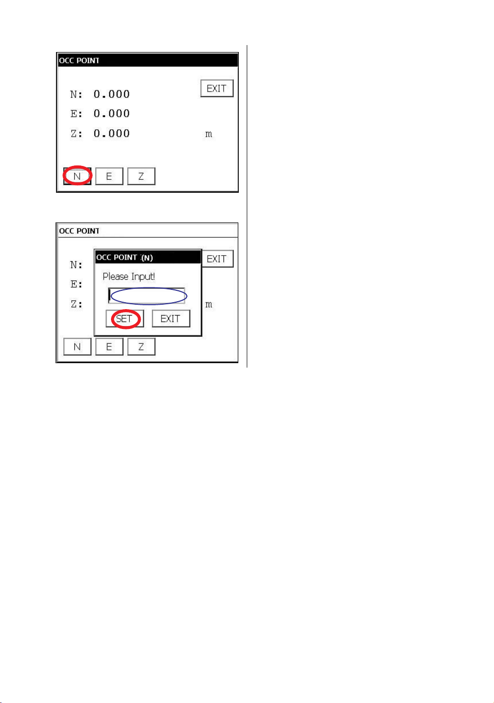
4 STANDARD MEASUREMENT MODE
4
Press the [N] key.
5
Input the N coord.
6
Press the [SET] key.*1)
7
Press the [E] key.
8
Input the E coord.
9
Press the [SET] key.*1)
10
Press the [Z] key.
11
Input the Z coord.
12
Press the [SET] key.*1)
13
Press the [EXIT] key.
*1)To return to the previous mode, press the [EXIT] key.
The display returns to coordinate
measurement mode.
87
Page 90

4 STANDARD MEASUREMENT MODE
4.4.2 Setting of the Instrument Height / Reflector(Prism) Height
Measure the coordinates by entering the instrument height / reflector height, coordinates of unknown
point will be measured directly.
[Example] : Instrument height
Confirm the angle measurement mode.
1
Press the [ ] key.
2
Press the [P1] key to get on page 2.
3
Press the [INSHT] key .
The previous data will be shown.
4
Press the [INPUT] key.
*1)To return to the previous mode, press the [EXIT] key.
88
5
Input instrument height, and press [SET]
key.*1)
6
Press the [EXIT] key.
The display returns to coordinate
measurement mode.
Page 91

4 STANDARD MEASUREMENT MODE
4.4.3 Execution of Coordinate Measuring
Measure the coordinates by entering the instrument height and reflector height, coordinates of
unknown point will be measured directly.
When setting coordinate values of occupied point, see section 4.4.1“Setting Coordinate Values of
Occupied Point” .
When setting the instrument height and reflector height, see section 4.4.2“Setting of the Instrument
Height / Reflector(Prism) Height” .
The coordinates of the unknown point are calculated as shown below and displayed:
Coordinates of occupied point : (N
Instrument height : INST.HT
Reflector height : R.HT
Vertical distance(Relative elevation) : z
Coordinates of the center of the reflector,
originated from the center point of the instrument : (n,e,z)
Coordinates of unknown point : (N
N
=N0+n
1
E
+e
1=E0
Z
+INST.HT+z - R.HT
1=Z0
Coordinates of the center of the reflector, originated from the center point of the instrument (n,e,z)
Center point of the instrument
(No, Eo, Zo+INST.HT)
,E
,Z
)
0
0
0
,E
,Z
)
1
1
1
•
•
•
Unknown point
(N
1, E1, Z1)
Occupied point (No, Eo, Zo)
Origin (o, o, o)
Confirm the angle measurement mode.
1
Set coordinates values of occupied point
and instrument/reflector height. *1)
2
Set the direction angle of known point A. *2)
3
Collimate the reflector.
4
Press the [ ] key.
Measuring starts.
*1) In case the coordinate of occupied point is not entered, (0,0,0) will be used as the default for the
occupied point.
The instrument height will be calculated as 0 when the instrument height is not entered.
The reflector height will be calculated as 0 when the reflector height is not set.
*2) Refer to section 4.2.3“Measuring from the Required Horizontal Angle” .
89
Page 92

4 STANDARD MEASUREMENT MODE
4.5 Data Output
Result of measurement is transferred from the IS series to Data Collector.
[Example: Distance measurement mode]
1
With the SETUP mode, set the communication
parameters.
Refer to Chapter 6 “PARAMETERS SETTING
MODE” .
2
After setting the communication parameters,
select the distance measurement mode.
3
Operate the data collector to measure the
distance.
Measurement will be started.
After the measurement, the result will be
shown and transferred to the Data Collector.
The following data will be output at each mode.
Mode Output
Angle mode ( V,HR or HL) ( V in percent) V, HR (or HL)
Horizontal distance mode (V,HR, HD, VD) V, HR, HD, VD
Slope distance mode (V, HR,SD) V, HR, SD,HD
Coordinate mode N, E, Z, HR
•
The display and the output at the coarse mode are the same as the contents above.
•
Output at the tracking mode is displayed as distance data only (HD,VD or SD).
90
Page 93

4 STANDARD MEASUREMENT MODE
4.6 Data Output by [REC] Key
It is also possible to output the result of measurement by pressing the [REC] key .
[Example: Distance measurement mode]
1
With the SETUP mode, set the communication
parameters.
Refer to Chapter 6 “PARAMETERS SETTING
MODE” .
2
After setting the communication parameters,
select the distance measurement mode.
3
Press the [REC] key.
Measurement will be started.
4
After the measurement, press the [Yes] key.
The data will be transferred to the Data
Collector.
91
Page 94

4 STANDARD MEASUREMENT MODE
4.7 Data output of IS series
The information of IS series regarding tracking auto-tracking are added to the protocol of Topcon Total
Station system so far.
Also you can add utility information such as battery remaining, EDM mode, auto-tracking mode, normal/
reversed face information, Tilt information if you like. For selecting, refer to Chapter 6 “PARAMETERS
SETTING MODE” .
During an utility function selection, measurement will be continued whenever tilt over. The tilt over will
not be compensated here.
In case tilt over, the tilt information will be displayed on the right-lower screen as the following marks
during the utility function is selected.
Marks Status of tilt
[t] Under tilt compensation
[?] Tilt Over
[*]
Tilt information
Tilt OFF
• Control by interface for Topcon AP-L1A system, see Chapter 5.5 “AP-L1A Communication
Emulator” .
92
Page 95

5PROGRAM MODE
Select the menu by pressing panel icon.
Main menu
Program mode menu
5 PROGRAM MODE
Press the [PROG] icon.
Edge abstraction mode
Refer to Chapter 5.6 “Edge Abstraction Mode” .
Repetition angle measurement
Refer to Chapter 5.4 “Repetition Angle Measurement (REP)” .
Missing line measurement
Refer to Chapter 5.3 “Missing Line Measurement (MLM)” .
Remote elevation measurement
Refer to Chapter 5.2 “Remote Elevation Measurement (REM)” .
Setting a direction angle for backsight orientation
Refer to Chapter 5.1 “Setting a Direction Angle for Backsight Orientation(BS)” .
Setting AP-L1A communication
Refer to Chapter 5.5 “AP-L1A Communication Emulator” .
93
Page 96

5 PROGRAM MODE
5.1 Setting a Direction Angle for Backsight Orientation(BS)
(Entering the instrument and backsight coordinate values)
This program uses the input coordinate values of the occupied point, (instrument), and backsight point
to calculate the backsight orientation direction angle.
The occupied and backsight coordinate input display appears.
After the coordinate values are entered for both points, the instrument calculates the backsight direction
angle for orientation.
Also the occupied coordinate values are stored in memory. The program does not store the backsight
coordinate values in memory.
N
Backsight point A
Direction angle
Example: Occupied point C : N coordinate 5.321m, E coordinate 8.345m
Backsight point A : N coordinate 54.321m, E coordinate 12.345m
Occupied point C
1
Press the [BS] icon.
E
94
Page 97

5 PROGRAM MODE
2
Input N and E coordinate of occupied point C.
Example : N coordinate; 5.321m
: E coordinate; 8.345m
3
Input N and E coordinate of backsight point A.
Example : N coordinate; 54.321m
: E coordinate; 12.345m
4
To memorize the occupied point, press the
[SET OCC] key.
5
Press the [YES] key.
6
Press the [SET] key.
7
Collimate the backsight.
8
Press the [YES] key.
The display returns to Program mode menu.
95
Page 98

5 PROGRAM MODE
5.2 Remote Elevation Measurement (REM)
The Remote Elevation program calculates the vertical distance (height) of a remote object relative to a
prism and it's height from a ground point, (without a prism height). When using a prism height, the
remote elevation measurement will start from the prism (reference point). If no prism height is used, the
remote elevation will start from any reference point in which the vertical angle is established. In both
procedures, the reference point should be perpendicular to the remote object.
Target K
Instrument
1) With prism height input
Prism P
G
1
Press the [REM] icon.
2
Select the [YES] button.
VD
Prism height
96
3
Input the Prism Height. (Example;1.000m)
4
To memorize the prism height, press the [SET]
key.
Page 99

5
Press the [YES] key.
6
Collimate prism.
7
Press the [Meas Prism] key.
5 PROGRAM MODE
8
Press the [SET] key.
(To measure the distance again, press the
[RE-TRY] key.)
9
Collimate target K.
Vertical angle(VA) and Vertical distance(VD)
will be shown.
97
Page 100

5 PROGRAM MODE
2)Without prism height input
1
Press the [REM] icon.
2
Select the [NO] button.
3
Collimate prism.
4
Press the [Meas Prism] key.
5
Press the [SET] key.
6
Collimate ground point G.
7
Press the [Meas Ground] key.
8
Press the [SET] key.
9
Collimate target K.
Vertical angle(VA) and Vertical distance(VD)
will be shown.
98
 Loading...