

Topcon HiPer Lite Operator's Manual
PRECISION GPS+: HiPer Lite
HiPer
Operator’s Manual


HiPer Lite
Operator’s Manual
Part Number 7010-0557
Rev A
©Copyright Topcon Positioning Systems, Inc.
All contents in this manual are copyrighted by Topcon. All
rights reserved. The information contained herein may not be
used, accessed, copied, stored, displayed, sold, modified,
published, or distributed, or otherwise reproduced without
Topcon only sells GPS products into Precision Markets.
Please go to www.topcongps.com for detailed market information.
June, 2003
express written consent from Topcon.

ECO#2049

Table of Contents
Preface .................................................................. xi
Terms and Conditions ...................................................... xi
Regulatory Information ................................................... xiv
Manual Conventions ........................................................ xvi
Chapter 1
Introduction .......................................................... 1-1
Overview .......................................................................... 1-2
Principles of Operation .................................................... 1-2
GPS Overview ........................................................... 1-2
Calculating Positions .......................................... 1-3
GPS Positioning .................................................. 1-4
Conclusion .......................................................... 1-5
Receiver Overview .................................................... 1-5
Standard Package Contents .............................................. 1-7
Cables ........................................................................ 1-7
Software .................................................................... 1-8
Literature ................................................................... 1-8
Getting Acquainted .......................................................... 1-9
Internal Components ................................................. 1-10
GPS+ antenna ..................................................... 1-10
Bluetooth Module ............................................... 1-10
Radio Modem ..................................................... 1-10
Power Board ....................................................... 1-11
GPS+ Receiver Board ......................................... 1-11
Battery ................................................................ 1-12
External Components ................................................ 1-12
Bottom Panel ...................................................... 1-12
Radome ............................................................... 1-13
i
1-866-4TOPCON www.topconpositioning.com

Table of Contents
Front Panel .................. .... ..... ............................... 1-14
Back Panel .......................................................... 1-15
Option Authorized File (OAF) ......................................... 1-16
Chapter 2
Configuration ....................................................... 2-1
Powering the HiPer Lite ................................................... 2-2
Internal batteries ........................................................ 2-2
External Batteries ...................................................... 2-3
Battery Charger ......................................................... 2-4
Turning On/Off the HiPer Lite .................................. 2-4
Connecting the HiPer Lite and a Computer ..................... 2-4
Establishing a Wireless Connection .......................... 2-5
Establishing an RS232 Cable Connection ................. 2-6
Establishing a PC-CDU Connection ......................... 2-6
HiPer Lite Configuration ................................................. 2-9
Power Management ............... ..... .... ........................... 2-14
Charging Internal Batteries ................................. 2-19
Checking Internal Battery Status ........................ 2-20
MINTER Configuration ................................................... 2-20
Radio Configuration ......................................................... 2-28
Bluetooth Module Configuration ..................................... 2-35
Collecting Almanacs ........................................................ 2-40
Chapter 3
Setup and Survey ................................................. 3-1
HiPer Lite Receiver Setup ............................................... 3-1
Step 1: Set up HiPer Lite Receiver ............................ 3-2
Step 2: Measure Antenna Height ............................... 3-2
Step 3: Collect Data ................................................... 3-4
Surveying with the HiPer Lite ......................................... 3-5
Static Survey .............................................................. 3-5
Kinematic (Stop and Go) Survey .............................. 3-8
Real-time Kinematic Survey ..................................... 3-10
ii
Topcon HiPer Lite Operator’s Manual
Set up an RTK Base Station ............................... 3-10
Setting up an RTK Rover .................................... 3-14

Table of Contents
Chapter 4
Operation .............................................................. 4-1
Using the MINTER .......................................................... 4-1
Power Key ................................................................. 4-2
Status LED ................................................................ 4-2
Reset Key .................................................................. 4-2
FN Key and Record LED .......................................... 4-2
Battery LED .............................................................. 4-6
Modem LED .............................................................. 4-6
Information Modes ............................................. .... ... 4-7
Normal ................................................................ 4-7
Extended Information Mode (EIM) .................... 4-7
Downloading Files to a Computer ................................... 4-9
Deleting Files ................................................................... 4-12
Checking an OAF ............................................................ 4-14
Loading OAFs ................................................................. 4-16
Managing HiPer Lite Memory ......................................... 4-17
Clearing the NVRAM ...................................................... 4-17
Using MINTER to Clear NVRAM ........................... 4-18
Using PC-CDU to Clear NVRAM ............................ 4-18
Changing Receiver Modes ............................................... 4-19
Sleep Mode ................................................................ 4-19
Zero Power Mode ...................................................... 4-20
Checking Firmware Version ............................................ 4-21
Loading New Firmware ................................................... 4-22
Receiver and Power Board Firmware ....................... 4-23
Bluetooth Module Firmware ..................................... 4-27
Chapter 5
Troubleshooting ................................................... 5-1
Power Problems ............................. .... ..... ......................... 5-2
Receiver Problems ........................................................... 5-3
Bluetooth Problems ......................................................... 5-8
Radio Modem Problems .................................................. 5-12
1-866-4TOPCON www.topconpositioning.com
iii

Table of Contents
Appendix A
Specifications ....................................................... A-1
HiPer Lite Specifications ................................................. A-1
Connector Specifications ................................................. A-9
Radio (Modem) RF Connector .................................. A-9
Power Connector ....................................................... A-10
Serial C-RS232 Connector ........................................ A-11
Appendix B
Safety Warnings ................................................... B-1
General Warnings ............................................................ B-1
Internal Battery Pack Warnings ....................................... B-2
Usage Warnings ............................................................... B-3
Appendix C
Warranty Terms .................................................... C-1
Index
iv
Topcon HiPer Lite Operator’s Manual

List of Figures
Chapter 1
Introduction .......................................................... 1-1
HiPer Lite Receiver ......................................................... 1-1
HiPer Lite Radome .......................................................... 1-13
HiPer Lite Front Panel ..................................................... 1-14
HiPer Lite Back Panel ..................................................... 1-15
Chapter 2
Configuration ........................................................ 2-1
PC-CDU Main Screen ..................................................... 2-7
Click File->Connect ........................................................ 2-7
Bluetooth and RS232 Connection Parameters ................. 2-8
PC-CDU Connection Established .................................... 2-8
Configuration->Receiver ................................................. 2-9
Receiver Configuration .................................................... 2-10
Receiver Configuration – MINTER Tab ......................... 2-10
Receiver Configuration – Advanced Tab ........................ 2-11
Advanced Configuration – Multipath Reduction ............ 2-12
Advanced Configuration – Loop Management ............... 2-13
Click Disconnect then Exit .............................................. 2-13
Configuration->Receiver ................................................. 2-14
Select Power Mode .......................................................... 2-14
Select Charger Mode ....................................................... 2-15
Select Power Output Modes – Ports ................................ 2-16
Select Power Output Modes – Slots ................................ 2-17
View Voltages Information ............................................. 2-17
Enable and Apply Power Settings ................................... 2-18
HiPer Lite MINTER ........................................................ 2-20
Connection Parameters – MINTER Settings ................... 2-22
v
1-866-4TOPCON www.topconpositioning.com

List of Figures
Configuration->Receiver ................................................. 2-22
Receiver Configuration – MINTER Tab ......................... 2-23
Run Modem-TPS ............................................................. 2-29
Modem-TPS Installation Wizard – Default Directory ..... 2-29
Modem-TPS Installation .................................................. 2-29
Modem-TPS Installation Complete ................................. 2-30
Uninstall Modem-TPS ..................................................... 2-30
Modem-TPS Connection Dialog Box .............................. 2-31
Modem-TPS Radio Link Tab ........................................... 2-32
Modem-TPS Serial Interface Tab .................................... 2-33
Modem-TPS Identification Tab ....................................... 2-33
About Modem-TPS ............. ..... .... .................................... 2-34
Click Disconnect then Exit .............................................. 2-34
Bluetooth Module Configuration Main Screen ................ 2-36
Select Communication Port and Click Connect ............... 2-36
BTCONF Identification Tab ............................................ 2-37
BTCONF Parameters Tab ................................................ 2-38
BTCONF Security Parameters ......................................... 2-39
BTCONF Serial Interface Tab ......................................... 2-39
Click Disconnect then Exit .............................................. 2-40
vi
Chapter 3
Setup and Survey ................................................. 3-1
HiPer Lite Antenna Offsets .............................................. 3-3
Configuration->Receiver->MINTER .............................. 3-7
Advanced->Multipath ...................................................... 3-7
Advanced->Loop Management ....................................... 3-8
Rover MINTER Configuration ........................................ 3-9
Set All Parameters to Defaults ......................................... 3-11
Receiver Configuration – Positioning .............................. 3-11
Base Tab Configuration ................................................... 3-12
Base Configuration – Ports .............................................. 3-13
HiPer Lite Rover Station Setup ........................................ 3-14
Rover Tab Configuration ................................................. 3-15
Rover Configuration – Ports ............................................ 3-17
PC-CDU Main Screen ...................................................... 3-17
Topcon HiPer Lite Operator’s Manual

List of Figures
Chapter 4
Operation .............................................................. 4-1
MINTER .......................................................................... 4-1
Connection Parameters – RTS/CTS Handshaking .......... 4-9
File->File Manager .......................................................... 4-9
Find Files to Download ....................................... ..... .... ... 4-10
Download Files ................................................................ 4-11
Download Files – Status Indicators ................................. 4-11
Click Disconnect then Exit .............................................. 4-12
Connection Parameters – RTS/CTS Handshaking .......... 4-12
File->Manager ................................................................. 4-13
Delete Files ...................................................................... 4-13
Tools->Receiver Options ................................................. 4-14
Option Manager ............................................................... 4-15
Load OAF ........................................................................ 4-16
Tools->Clear NVRAM .................................................... 4-18
Help->About .................................................................... 4-21
About PC-CDU ................................................................ 4-21
FLoader Main Screen ...................................................... 4-23
Set Device Type ............................................................... 4-24
Program Tab Settings ...................................................... 4-24
Set Device Type ............................................................... 4-25
Program Tab Settings ...................................................... 4-26
Get Device Type .............................................................. 4-27
Program Tab Settings ...................................................... 4-28
Bluetooth Firmware Load Complete ............................... 4-28
Appendix A
Specifications ....................................................... A-1
Power Connector .................................... .... ..... .... ............ A-10
RS232 Connector ............................................................. A-11
1-866-4TOPCON www.topconpositioning.com
vii

LIst of Figures
Notes:
viii
Topcon HiPer Lite Operator’s Manual

List of Tables
Chapter 1
Introduction ........................................................... 1-1
Euro Card Options ........................................................... 1-11
Chapter 2
Configuration ......................................................... 2-1
Data Recording Parameter Behavior ............................... 2-27
Chapter 3
Setup and Survey ................................................... 3-1
HiPer Lite Antenna Offset Values for GD Options ......... 3-3
Chapter 4
Operation ............................................................... 4-1
FN Key Functions and REC LED Status ......................... 4-4
Signal-to-Noise (S/N) “Good” Ratios ............................. 4-8
Appendix A
Specifications ......................................................... A-1
HiPer Lite Specifications ................................................. A-1
Spread Spectrum Modem Connector Specifications ....... A-9
Power Connector Specifications ...................................... A-10
RS232 Connector Specifications ..................................... A-11
ix
1-866-4TOPCON www.topconpositioning.com

List of Tables
Notes:
x
Topcon HiPer Lite Operator’s Manual

Preface
Thank you for purchasing this Topcon product. The materials
available in this Manual (the “Manual”) have been prepared by
Topcon Positioning Systems, Inc. (“TPS”) for owners of Topcon
products, and is designed to assist o wners with the use of the HiPer
Lite and its use is subject to these terms and conditions (the “Terms
and Conditions”).
NOTICE
Please read these Terms and Conditions
carefully.
Terms and Conditions
PROFESSIONAL USE – This product is designed to be used by a
professional. The user is required to be a professional surveyor or
have a good knowledge of surveying, in order to understand the
user and safety instructions, before operating, inspecting or
adjusting. Always wear required safety attire (safety shoes, hard
hat, etc.) when operating.
COPYRIGHT – All information contained in this Manual is the
intellectual property of, and copyrighted material of TPS. All rights
are reserved. You may not use, access, copy, store, display, create
derivative wo rks of, sell, modify, publish, distribute, or allow any
third party access to, any graphics, content, information or data in
this Manual without TPS’ ex press written consent and may only use
such information for the care and operation of your HiPer Lite. The
information and data in this Manual are a valuable asset of TPS and
1-866-4TOPCON www.topconpositioning.com
xi

Preface
are developed by the ex penditure of considerable work, time and
money, and are the result of original selection, coordination and
arrangement by TPS.
TRADEMARKS – HiPer™, HiPer Lite™, Topcon Tools™,
Topcon® and Topcon Positioning Systems™ are trademarks or
registered trademarks of TPS. Windows® is a registered trademark
of Microsoft Corporation. Bluetooth™ is a trademark owned by
Bluetooth SIG, Inc. and is used by Topcon Positioning Systems,
Inc. under license. Product and company names mentioned herein
may be trademarks of their respective owners.
xii
DISCLAIMER OF WARRANTY
– EXCEPT FOR ANY
WARRANTIES IN APPENDIX C OR A WARRA NTY CARD
ACCOMPANYING THE PR ODUCT, THIS MANUAL AND THE
HIPER LITE ARE PROVIDED “AS-IS.” THERE ARE NO
OTHER WARRANTIES. TPS DISCLAIMS ANY IMPLIED
WARRANTY OF MERCHANTABILITY OR FITNESS FOR
ANY PARTICULAR USE OR PURPOSE. TPS AND ITS
DISTRIBUTORS SHALL NOT BE LIABLE FOR TECHNICAL
OR EDITORIAL ERRORS OR OMISSIONS CONTAINED
HEREIN; NOR FOR INCIDENTAL OR CONSEQUENTIAL
DAMAGES RESULTING FROM THE FURNISHING,
PERFORMANCE OR USE OF THIS MATERIAL OR THE HiPer
Lite. SUCH DISCLAIMED D A MAGES INCLUDE BUT ARE
NOT LIMITED TO LOSS OF TIME, LOSS OR DESTRUCTION
OF DATA, LOSS OF PROFIT, SAVINGS OR REVENUE, OR
LOSS OF THE PRODUCT’S USE. IN ADDITION TPS IS NOT
RESPONSIBLE OR LIABLE FOR DAMAGES OR COSTS
INCURRED IN CONNECTION WITH OBTAINING
SUBSTITUTE PRODUCTS OR SOFTWARE, CLAIMS BY
OTHERS, INCONVENIENCE, OR ANY OTHER COSTS. IN
ANY EVENT, TPS SHALL HAVE NO LIABILITY FOR
DAMAGES OR OTHERWISE TO YOU OR ANY OT HER
Topcon HiPer Lite Operator’s Manual

Terms and Conditions
PERSON OR ENTITY IN EXCESS OF THE PURCHASE PRICE
FOR THE HIPER LITE.
LICENSE AGREEMENT – Use of any computer programs or
software supplied by TPS or downloaded from a TPS website (the
“Software”) in connection with the HiPer Lite constitutes
acceptance of these Terms and Conditions in this Manual and an
agreement to abide by these Terms and Co nditions. The user is
granted a personal, non-exclusive, non-transferable license to use
such Software under the terms stated herein and in any case only
with a single HiPer Lite or single computer. You may not assign or
transfer the Software or this license without the express written
consent of TPS. This license is effective until terminated. You may
terminate the license at any time by destroying the Software and
Manual. TPS may terminate the license if you fail to comply with
any of the Terms or Conditions. You agree to destroy the Software
and manual upon termination of your use of the HiPer Lite. All
ownership, cop yright and other inte llectual property rights in and to
the Software belong to TPS. If these license terms are not
acceptable, return any unused software and manual.
CONFIDENTIALITY – This Manual, its contents and the
Software (collectively, the “Confidential Information”) are the
confidential and proprietary information of TPS. You agre e to tre at
TPS’ Confidential Information with a de gree of care no less stringent
that the degree of care you would use in safeguarding your o wn most
valuable trade secrets. Nothing in this paragraph shall restrict you
from disclosing Confidential Information to your employees as may
be necessary or appropriate to operate or care for the HiPer Lite. Such
employees must also keep the Conf identiality Information
confidential. In the e v ent you beco me legally compelled to disclose
any of the Confidential Information, you shall give TPS immediate
notice so that it may seek a protecti v e order or other app ropriate
remedy.
1-866-4TOPCON www.topconpositioning.com
xiii

Preface
WEBSITE; OTHER STATEMENTS – No statemen t contained at
the TPS website (or any other website) or in any other
advertisements or TPS literature or made by an employee or
independent contractor of TPS modifies these Terms and
Conditions (including the Software license, warranty and limitation
of liability).
SAFETY – Improper use of the HiPer Lite can lead to injury to
persons or property and/or malfunction of the product. The HiPer
Lite should only be repaired by authorized TPS warranty service
centers. Users should review and heed the safety warnings in
Appendix B.
MISCELLANEOUS – The above Terms and Conditions may be
amended, modified, superseded, or canceled, at any time by TPS.
The above Terms and Conditions will be governed by, and
construed in accordance with, the laws of the State of California,
without reference to conflict of laws.
xiv
Regulatory Information
The following sections provide information on this product’s
compliance with government regulations.
FCC Class B Compliance
This device complies with Part 15 of the FCC rules. Operation
is subject to the following two conditions:
1. This device may not cause harmful interference, and
2. This device must accept any interference received,
including interference that may cause un desired operation.
This equipment has been tested and found to comply with the
limits for a Class B digital device, pursuant to Part 15 of the
FCC rules. These limits are designed to provide reasonable
protection against harmful interference in residential
Topcon HiPer Lite Operator’s Manual

Regulatory Information
installations. This equipment generates, uses, and can radiate
radio frequency energy, and if not installed and used in
accordance with the instructions, may cause harm ful
interference to radio communications. However, there is no
guarantee that interference will not occur in a particular
installation.
If this equipment does cause interference to radio or television
equipment reception, which can be determined by turning the
equipment off and on, the user is encouraged to try to correct
the interference by on or more of the following measures:
• Reorient or relocate the receiving antenna.
• Move the equipment away from the receiver.
• Plug the equipment into an outlet on a circuit different from
that to which the receiver is powered.
• Consult the dealer or an experienced radio/television
technician for additional suggestions.
CAUTION
Any changes or modifications to the
equipment not expressly approved by the
party responsible for compliance could void
your authority to operate such equipment.
Canadian Emissions Labeling
Requirements
This Class B digital apparatus meets all requirements of the
Canadian Interference-Causing Equipment Regulations.
Cet appareil numérique de la classe B respecte toutes les
exigences du Réglement sur le matériel brouilleur du Canada.
1-866-4TOPCON www.topconpositioning.com
xv

Preface
Manual Conventions
This manual uses the following conventions:
Example Description
File->Exit Click the File menu and click Exit.
Enter Press or click the button or key labeled Enter.
TIP
Supplementary information that can help you
configure, maintain, or set up a system.
NOTICE
Supplementary information that can have an
affect on system operation, system performance,
measurements, or personal safety.
CAUTION
Notification that an action has the potential to
adversely affect system operation, system
performance, data integrity, personal health.
WARNING
Notification that an action will result in
system damage, loss of data, loss of
warranty, or personal injury.
DANGER
xvi
UNDER NO CIRCUMSTANCES SHOULD THIS ACTION
BE PERFORMED.
Topcon HiPer Lite Operator’s Manual
Introduction
This chapter describes:
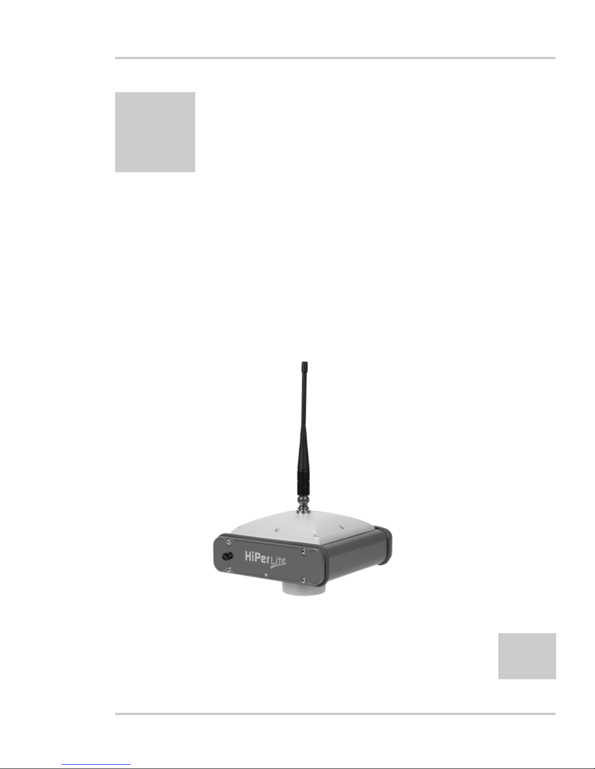
• The HiPer Lite (Figure 1-1)
• GPS and your receiver
• Common HiPer Lite functions
• Standard package contents and configurations
• HiPer Lite components
• The Option Authorized File (OAF)
Chapter 1
1-866-4TOPCON www.topconpositioning.com
Figure 1-1. HiPer Lite Receiver
1-1

Introduction
Overview
Topcon Positioning System’s HiPer Lite is a dual-frequency, GPS+
receiver built to be the most advanced and compact receiver for the
surveying market. The HiPer Lite is a multi-function, multi-purpose
receiver intended for precision markets. Precision markets means
markets for equipment, subsystems, components and software for
surveying, construction, commercial mapping, civil engineering,
precision agriculture and land-based construction and agriculture
machine control, photogrammetry mapping, hydrographic and any
use reasonably related to the foregoing.
The HiPer Lite can receive and process both L1 and L2 signals,
improving the accuracy of your survey points and positions. The
dual-frequency and GPS+ features of the HiPer Lite combine to
provide the only real time kinematic (RTK) system accurate for
short and long baselines. Several other features, including multipath
mitigation and co-op tracking, provide under-canopy and low
signal strength reception. The HiPer Lite receiver provides the
functionality, accuracy, availability , and integrity needed for fast
and easy data collection.
1-2
Principles of Operation
Surveying with the right GPS receiver can provide users accurate
and precise positioning, a requirement for any surveying project.
This section gives an overview of GPS and receiver functions to
help you understand and apply GPS principles, allowing you to get
the most out of your receiver.
GPS Overview
The Global Positioning System (GPS), run by the United States
Department of Defense (DoD), is a network of up to 28
satellites (at time of printing) orbiting the earth every 12 hours.
The Global Navigation Satellite System (GLONASS), is the
Russian Federation Ministry of Defense counterpart to GPS. At
Topcon HiPer Lite Operator’s Manual

Principles of Operation
any one time, with a standard 15 degree angle, up to 10 or 12
GPS satellites are visible from any point on earth. When a
receiver can also track GLON ASS satellites, between 10 and 16
satellites are visible.
The GPS and GLONASS network has three components:
• Space – GPS and GLONASS satellites orbiting
approximately 12,000 nautical miles above Earth and are
equipped with a clock and radio. These satellites broadcast
digital information (ephemerides, almanacs, time frequency
corrections, etc.).
• User – The community and military that use GPS/
GLONASS receivers and the corresponding satellites to
calculate positions.
• Control – Ground stations located around the Earth that
upload data, including clock corrections and new
ephemerides (satellite positions as a function of time), to
ensure the satellites transmit data properly.
GPS receivers use ephemeris and almanac data to calculate
accurate positions, and the positions of your survey points.
Calculating Positions
Once the receiver locks on to a satellite, it starts recording
measurements and receiving the various di gital information
(ephemeris, almanac, and so on) the satellites broadcast. To
calculate a position, receivers use the following basic
formula:
Velocity x Time = Distance
Where Velocity is the speed at which radio waves travel
(i.e., the speed of light) and Time is the difference between
the signal transmission time and signal reception time.
To calculate absolute 3-D positions—latitude, longitude,
altitude—the receiver must lock on to four satellites. In a
1-866-4TOPCON www.topconpositioning.com
1-3

Introduction
mixed, GPS and GLONASS scenario, receiver’s must lock
onto at least five satellites to obtain an absolute position.
To provide fault tolerance using only GPS or only
GLONASS, the recei v er must lock onto a fifth satellite. S ix
satellites will provide fault tolerance in mixed scenarios.
Usually, the number of GPS and GLONASS satellites in
view does not exceed twenty (20).
Once locked on to a satellite, the receiver collects
ephemerides and almanacs, saving this information to its
NVRAM (Non-Volatile RAM).
• GPS and GLONASS satellites broadcast ephemeris
data cyclically, with a period of 30 seconds.
• GPS satellites broadcast almanac data cyclically with a
period of 12.5 minutes; GLONASS satellites broadcast
almanac data cyclically with a period of 2.5 minutes.
1-4
GPS Positioning
Calculating an accurate position requires the following
three elements:
• Accuracy – The accuracy of a position depends upon
the number, signal integrity, and placement (also
known as Dilution of Precision, or DOP) of satellites.
–Differential GPS (DGPS) strongly mitigates
atmospheric and orbital errors, and counteracts antispoofing signals the US Department of Defense
transmits with GPS signals.
–The more satellites in view, the stronger the signal,
the lower the DOP number, providing more accurate
positioning.
• Availability – The availability of satellites affects the
calculation of valid positions. The more visible
satellites available, the more valid and accurate the
position. Natural and man-made objects can block,
Topcon HiPer Lite Operator’s Manual

Principles of Operation
interrupt, and weaken signals, lowering the number of
available satellites.
• Integrity – Fault tolerance allows a position to have
greater integrity, increasing accuracy. Several factors
combine to provide fault tolerance, including:
–Receiver Autonomous Integrity Monitoring (RAIM)
detects faulty GPS and GLONASS satellites and
removes them from the position calculation.
–Wide Area Augmentation System (WAAS) creates
and transmits DGPS correction messages.
–Five or more visible satellites for only GPS or only
GLONASS; six or more satellites for mixed scenarios.
–Current ephemerides and almanacs.
–Several algorithms to detect and correct faulty
information.
Conclusion
Surveyors can use Topcon GPS+ receivers to collect data
from a network of satellites and control stations to
triangulate precise points anywhere on Earth.
This overview simply outlines the basics of GPS and
GLONASS positioning. For more detailed information,
visit the TPS website (www.topconps.com/gpstutorial/).
Receiver Overview
When power is turned on and the receiver self-test completes,
the receiver’s 40 channels initialize and begin tracking visible
GPS satellites. Each of the receiver’s channels can be used to
track C/A-L1, P-L1, or P-L2 signals. The number of channels
available allows the receiver to track all visible GPS satellites
at any time and location. The GPS antenna receives the
different signals for processing.
1-5
1-866-4TOPCON www.topconpositioning.com

Introduction
An internal GPS antenna equipped with an optional low noise
amplifier (LN A) and the receiv er’s radio frequency (RF) device
are connected with a coaxial cable. The wide-band signal
received is down-converted, filtered, digitized, and assigned to
different channels. The receiver processor controls the process
of signal tracking.
Once the signal is locked in the channel, it is demodulated and
necessary signal parameters (carrier and code phases) are
measured. Also, broadcast navigation data are retrieved from
the navigation frame.
After the receiver locks on to four or more satellites, it is
possible to solve the so-called “absolute positioning problem”
and compute the receiver’s coordinates and time (in WGS-84).
All this information is stored in the receiver’s memory, which
can be downloaded later onto a computer and processed using a
post-processing software package. When the receiver is run in
RTK mode, raw data measurements can also be recorded into
the receiver’s internal memory. This allows the operator to
double check real-time results obtained in the field.
1-6
Depending on your options, capabilities of the HiPer Lite
receiver include:
• Co-Op Tracking
• Multipath reduction
• Wide area augmentation system (WAAS)
• Adjustable phase locked loop (PLL) and delay lock loop
(DLL) parameters
• Dual-frequency static, kinematic, real-time kinematic
(RTK), and differential GPS (DGPS) survey modes
• Auto data logging
• Setting different mask angles
• Setting different survey parameters
Topcon HiPer Lite Operator’s Manual

Standard Package Contents
• Static or dynamic modes
Standard Package Contents
The HiPer Lite comes in a real-time kinematic (RTK) package with
two HiPer Lite receiver, one as a Base Station and the other as a
Rover Station (also, refer to the re-packaging instruction card). The
contents of this package include:
• Two HiPer Lite receivers
•LitePole
• Tripod, tribrach, an d adap ter
• Topcon Tools
• Cables and cords
•Literature
Cables
Standard package cables include:
• Receiver-to-computer RS232 serial cable
• Receiver-to-SAE power cable
• SAE-to-SAE cable extension
• Alligator clips-to-SAE cable
• Power/charger cable
• Power supply W/48” SAFECO connector
1-866-4TOPCON www.topconpositioning.com
1-7

Introduction
Software
Standard HiPer Lite software includes:
• PC-CDU – controller software that can run on a
Windows-based computer. Please refer to the PC-CDU
User’s Manual for detailed information on this software.
• Modem-TPS – Topcon’ s Spread Spectrum rad io/mod e m
configuration software.
• Topcon Tools – Topcon ’s post-processing software.
Software and software information are also available on the
Topcon website (www.topcongps.com/software/index.html or
http://www.topcongps.com/software/3rdparty.html).
The following software will also be useful for operating, caring
for and using your HiPer Lite receiver, and may be required for
some applications.
1-8
• FLoader – Topcon’s firmware loader; available on the
Topcon website.
• BTCONF – Topcon’s Bluetooth module configuration
program; available on the Topcon website.
• Survey Pro GPS – optional third-party software for data
collection and display; contact your TPS dealer.
• Carlson SurvCE – optional third-party software for data
collection; contact your TPS dealer.
Literature
HiPer Lite literature includes:
• One year warranty card
• HiPer Lite Operator’s Manual
• Functional specifications
Topcon HiPer Lite Operator’s Manual

Getting Acquainted
Manuals and other product information are also available on
the Topcon website.
• www.topcongps.com/support/manuals.html
• www.topcongps.com/hardware/index.html (then click on
the appropriate product)
The following manuals will also be useful for operating and
caring for your HiPer Lite receiver. These are also available on
the Topcon website (www.topcongps.com/support/
manuals.html).
• PC-CDU User’s Manual
• FLoader User’s Manual
• MINTER User’s Manual
Getting Acquainted
The HiPer Lite is 159mm wide, 172mm deep, 88mm high, weighs
1.65kg. The receiver’s advanced design allows users to
significantly reduce the number of cables required for receiver
operation, allowing the user to perform jobs more reliably and
efficiently, especially when the receiver is moving.
The HiPer Lite is also versatile and can be configured in several
different ways. The casing allocates space for two nonremovable,
on-board Li-Ion batteries, a Bluetooth™
module, and two Euro cards. One of those cards is the GPS receiver
and the other is used for spread spectrum communications.
The HiPer Lite has standard interior receiver components and two
end panels for user interface, communication, and power supply.
For HiPer Lite specifications, see Appendix A.
1
wireless technology
1. Bluetooth is a trademark owned by Bluetooth SIG, Inc. and is used
by Topcon Positioning Systems, Inc. under license.
1-866-4TOPCON www.topconpositioning.com
1-9

Introduction
Internal Components
Features inside the HiPer Lite casing include:
GPS+ antenna
An internal, micro-strip antenna capable of receiving GPS
L1/L2 signals.
Bluetooth Module
A combination of software and hardware technology that
makes the HiPer Lite a mobile, wireless, GPS+ receiver
that supports a point-to-point serial profile. As such, the
HiPer Lite can transfer and synchronize files between the
receiver and any other Bluetooth wireless technology
device that supports serial profile, including portable
handheld devices and external controllers, Bluetooth
adapters for PC-USB/RS ports, mobile computers and
phones, IPAQs, PCMCA-to-Bluetooth adapters, etc.
1-10
With Bluetooth wireless technology, the HiPer Lite
reception and transmission distance is 10 meters (32 feet)
for interior projects and 30–50 meters (98–164 feet) for
exterior projects.
The Bluetooth module’s processor and firmware are
independent of the receiver card and power board.
Radio Modem
The HiPer Lite incorporates an internal, spread spectrum,
915 MHz modem for receiving data from a Base station or
transmitting data to a Rover station. The Base station’s
modem transmits the carrier phase and code measurements
along with the reference station information (i.e., location
and description) to the Rover station modem.
The internal radio modem comes with a number of preset
channels programmed at TPS. Complete information
Topcon HiPer Lite Operator’s Manual
 Loading...