

Page 1
/PERATORlS-ANUAL
Page 2

Page 3

POSITIONING SYSTEMS
HiPer II
Operator’s Manual
Part Number 7010-0982
Rev C
December, 2010
All contents in this manual are copyrighted by Topcon. All rights reserved.
The information contained herein may not be used, accessed, copied, stored,
displayed, sold, modified, published, distributed, or otherwise reproduced
without express written consent from Topcon.
Page 4

ECO#3997
Page 5

TOC
Table of Contents
Preface .................................................................. ii-v
Chapter 1
Introduction .......................................................... 1-1
Principles of Operation .................................................... 1-2
GNSS Overview ........................................................ 1-2
Calculating Absolute Positions ........................... 1-3
Calculating Differential Positions ...................... 1-3
Essential Components for Quality Surveying .... 1-5
Conclusion .......................................................... 1-6
HiPer II Receiver ....................................................... 1-7
HiPer II Features ....................................................... 1-9
Battery ....................................................................... 1-10
Inserting and Removing the Battery ................... 1-11
Charging the Battery ........................................... 1-13
LED Display Panel .................................................... 1-16
Audible Annunciator ................................................. 1-21
Data and Power Ports ................................................ 1-22
External Radio Antenna Connector .......................... 1-23
Connector .................................................................. 1-24
SD/SDHC and SIM Card Slots ................................. 1-24
Serial Cable ............................................................... 1-27
Other Accessories ...................................................... 1-28
Optional Accessories ................................................. 1-28
Option Authorization File (OAF) .................................... 1-29
Chapter 2
Pre-survey Preparation ........................................ 2-1
Installing Topcon Software .............................................. 2-2
Installing TRU ........................................................... 2-2
Install the Optional
SD/SDHC and SIM Cards ............................................ 2-3
P/N 7010-0982
i
Page 6

Table of Contents
Connecting to the Receiver using TRU ............................ 2-3
Establishing a Serial Cable Connection ..................... 2-4
Establishing a Wireless Connection .......................... 2-5
Collecting Almanacs and Ephemerides ............................ 2-7
POWERUP Script ............................................................ 2-8
Example ............................................................... 2-9
POWERUP Script Requirements .............................. 2-9
Installing the POWERUP Script ................................ 2-9
Uninstall the POWERUP script ................................. 2-10
Editing the POWERUP Script ................................... 2-10
Enabling the POWERUP Script ................................ 2-10
Disable POWERUP script function ........................... 2-11
Chapter 3
HiPer II Configuration .......................................... 3-1
Managing the Radio Modem ............................................ 3-2
Connecting with the Radio Modem ........................... 3-2
Configuring a Digital UHF Radio Modem ............... 3-4
Configuring the Receiver ................................................. 3-7
Chapter 4
HiPer II Receiver Setup ....................................... 4-1
Receiver Setup .................................................................. 4-1
Step 1: Set up the Receivers ...................................... 4-1
Step 2: Measure Antenna Height ............................... 4-4
Static Surveying for Base Stations ................................... 4-6
Chapter 5
Receiver and File Maintenance .......................... 5-1
Downloading Files to a Computer ................................... 5-1
Downloading Files via TRU ...................................... 5-1
Deleting Files from the Receiver Using TRU .................. 5-3
Using the Power Button to Deleting Files ........................ 5-4
Managing Receiver Memory ............................................ 5-4
Managing Receiver Options ............................................. 5-4
Checking the Receiver’s OAF ................................... 5-5
Loading an OAF ........................................................ 5-5
Loading New Firmware ................................................... 5-7
ii
HiPer II Operator’s Manual
Page 7

Table of Contents
Clearing the NVRAM ...................................................... 5-8
Using TRU to Clear the NVRAM ............................. 5-9
Chapter 6
Troubleshooting ................................................... 6-1
Check This First! ............................................................. 6-1
Troubleshooting Quick List ............................................. 6-2
Powering Problems .......................................................... 6-2
Receiver Problems ........................................................... 6-4
Bluetooth Problems ......................................................... 6-8
TRU Problems ................................................................. 6-10
Obtaining Technical Support ........................................... 6-12
Phone ......................................................................... 6-12
Email ......................................................................... 6-12
Website ...................................................................... 6-13
Appendix A
Specifications ....................................................... A-1
Receiver Specifications ................................................... A-1
General Details .......................................................... A-1
GPS Board Details .................................................... A-5
Bluetooth Module Details ......................................... A-7
Internal Topcon UHF Modem General
Specification Details .............................................. A-7
Internal UHF Satel Modem Details ........................... A-8
Optional GSM/GPRS Module Details ...................... A-9
Battery (BDC58) Specifications ............................... A-10
Charger (CDC68) Specifications .............................. A-10
Connector Specifications ................................................. A-11
UHF Radio Modem Connector ................................. A-11
Power Connector ....................................................... A-12
Serial RS232 Connector ............................................ A-13
Appendix B
Safety Warnings ................................................... B-1
General Warnings .......................................................... B-1
Battery Pack Warnings .................................................. B-2
Usage Warnings ...................................................... B-3
P/N 7010-0982
iii
Page 8

Table of Contents
Appendix C
Regulatory Information ....................................... C-1
UHF Radio Usage ............................................................ C-1
FCC Compliance .............................................................. C-2
Federal Communication Commission
Declaration of Conformity (DoC) Statement ... C-3
Canadian Emission Labeling Requirements .................... C-3
IC RF Radiation Exposure Statement ................. C-4
IC Additional statement with
Detachable Antennas ....................................... C-4
Community of Europe Compliance .................................. C-5
European Community Declaration of Conformity
with R&TTE Directive 1999/5/EC .................. C-5
Declaration of Conformity with Regard to the
R&TTE Directive 1999/5/EC ....................................... C-6
WEEE Directive ............................................................... C-8
Appendix D
Warranty Terms ................................................... D-1
iv
HiPer II Operator’s Manual
Page 9
Preface
NOTICE
Preface
Thank you for purchasing this Topcon product. The materials
available in this Manual (the “Manual”) have been prepared by
Topcon for owners of Topcon products, and are designed to assist
owners with the use of the receiver and its use is subject to these
terms and conditions (the “Terms and Conditions”).
Please read these Terms and Conditions carefully.
Terms and Conditions
USE This product is designed to be used by a professional. The user
should have a good knowledge of the safe use of the product and
implement the types of safety procedures recommended by the local
government protection agency for both private use and commercial
job sites.
COPYRIGHT All information contained in this Manual is the
intellectual property of, and copyrighted material of Topcon. All
rights are reserved. Do not use, access, copy, store, display, create
derivative works of, sell, modify, publish, distribute, or allow any
third party access to, any graphics, content, information or data in this
Manual without Topcon’s express written consent and may only use
such information for the care and operation of the receiver. The
information and data in this Manual are a valuable asset of Topcon
and are developed by the expenditure of considerable work, time and
money, and are the result of original selection, coordination and
arrangement by Topcon.
P/N 7010-0982
v
Page 10

TRADEMARKS HiPer II™, TRU™, Topcon Tools™, Topcon
Link™, and FC2500™ are trademarks or registered trademarks of
Topcon. Windows® is a registered trademark of Microsoft
Corporation. The Bluetooth® word mark and logos are owned by
Bluetooth SIG, Inc. and any use of such marks by Topcon is used
under license. Other product and company names mentioned herein
may be trademarks of their respective owners.
DISCLAIMER OF WARRANTY EXCEPT FOR ANY
WARRANTIES IN AN APPENDIX OR A WARRANTY CARD
ACCOMPANYING THE PRODUCT, THIS MANUAL AND THE
RECEIVER ARE PROVIDED “AS-IS.” THERE ARE NO OTHER
WARRANTIES. TOPCON DISCLAIMS ANY IMPLIED
WARRANTY OF MERCHANTABILITY OR FITNESS FOR ANY
PARTICULAR USE OR PURPOSE. TOPCON AND ITS
DISTRIBUTORS SHALL NOT BE LIABLE FOR TECHNICAL OR
EDITORIAL ERRORS OR OMISSIONS CONTAINED HEREIN;
NOR FOR INCIDENTAL OR CONSEQUENTIAL DAMAGES
RESULTING FROM THE FURNISHING, PERFORMANCE OR
USE OF THIS MATERIAL OR THE RECEIVER. SUCH
DISCLAIMED DAMAGES INCLUDE BUT ARE NOT LIMITED
TO LOSS OF TIME, LOSS OR DESTRUCTION OF DATA, LOSS
OF PROFIT, SAVINGS OR REVENUE, OR LOSS OF THE
PRODUCT’S USE. IN ADDITION TOPCON IS NOT
RESPONSIBLE OR LIABLE FOR DAMAGES OR COSTS
INCURRED IN CONNECTION WITH OBTAINING
SUBSTITUTE PRODUCTS OR SOFTWARE, CLAIMS BY
OTHERS, INCONVENIENCE, OR ANY OTHER COSTS. IN ANY
EVENT, TOPCON SHALL HAVE NO LIABILITY FOR
DAMAGES OR OTHERWISE TO YOU OR ANY OTHER
PERSON OR ENTITY IN EXCESS OF THE PURCHASE PRICE
FOR THE RECEIVER.
LICENSE AGREEMENT Use of any computer programs or software
supplied by Topcon or downloaded from a Topcon website (the
“Software”) in connection with the receiver constitutes acceptance of
these Terms and Conditions in this Manual and an agreement to abide
by these Terms and Conditions. The user is granted a personal, nonexclusive, non-transferable license to use such Software under the
vi
HiPer II Operator’s Manual
Page 11

Terms and Conditions
terms stated herein and in any case only with a single receiver or
single computer. You may not assign or transfer the Software or this
license without the express written consent of Topcon. This license is
effective until terminated. You may terminate the license at any time
by destroying the Software and Manual. Topcon may terminate the
license if you fail to comply with any of the Terms or Conditions.
You agree to destroy the Software and manual upon termination of
your use of the receiver. All ownership, copyright and other
intellectual property rights in and to the Software belong to Topcon.
If these license terms are not acceptable, return any unused software
and manual.
CONFIDENTIALITY This Manual, its contents and the Software
(collectively, the “Confidential Information”) are the confidential and
proprietary information of Topcon. You agree to treat Topcon’s
Confidential Information with a degree of care no less stringent that the
degree of care you would use in safeguarding your own most valuable
trade secrets. Nothing in this paragraph shall restrict you from
disclosing Confidential Information to your employees as may be
necessary or appropriate to operate or care for the receiver. Such
employees must also keep the Confidentiality Information confidential.
In the event you become legally compelled to disclose any of the
Confidential Information, you shall give Topcon immediate notice so
that it may seek a protective order or other appropriate remedy.
WEBSITE; OTHER STATEMENTS No statement contained at the
Topcon website (or any other website) or in any other advertisements
or Topcon literature or made by an employee or independent
contractor of Topcon modifies these Terms and Conditions (including
the Software license, warranty and limitation of liability).
SAFETY Improper use of the receiver can lead to injury to persons or
property and/or malfunction of the product. The receiver should only
be repaired by authorized Topcon warranty service centers. Users
should review and heed the safety warnings in an Appendix.
MISCELLANEOUS The above Terms and Conditions may be
amended, modified, superseded, or canceled, at any time by Topcon.
The above Terms and Conditions will be governed by, and construed
P/N 7010-0982
vii
Page 12
in accordance with, the laws of the State of California, without
NOTE
TIP
NOTICE
CAUTION
reference to conflict of laws.
Manual Conventions
This manual uses the following conventions:
Example Description
FileExit Click the File menu, and click Exit.
Connection Indicates the name of a dialog box or screen.
Frequency Indicates a field on a dialog box or screen, or a tab
within a dialog box or screen.
Enter Press or click the button or key labeled Enter.
Further information to note about the configuration,
maintenance, or setup of a system.
viii
Supplementary information that can help to
configure, maintain, or set up a system.
Supplementary information that can have an affect
on system operation, system performance,
measurements, or personal safety.
Notification that an action has the potential to
adversely affect system operation, system
performance, data integrity, or personal health.
HiPer II Operator’s Manual
Page 13

Manual Conventions
WARNING
DANGER
Notification that an action will result in system
damage, loss of data, loss of warranty, or personal
injury.
Under no circumstances should this action be
performed.
P/N 7010-0982
ix
Page 14

Notes:
x
HiPer II Operator’s Manual
Page 15
Introduction
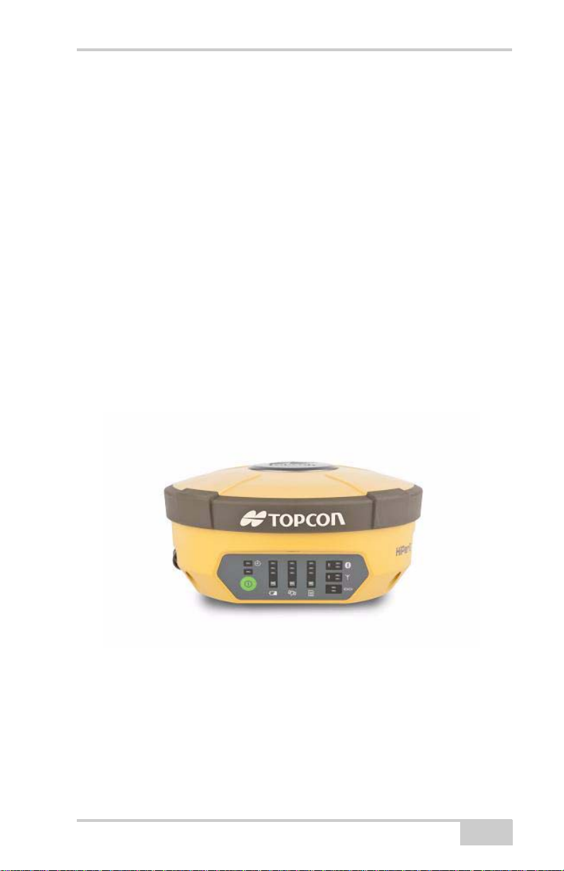
The HiPer II receiver is a multi-frequency GNSS receiver, built to be
the most advanced and compact receiver of its kind for the surveying
and construction markets.
The HiPer II can receive and process GNSS signals on the L1 and L2
frequencies of both the GPS and GLONASS satellite navigation
systems. This multi-frequency and multi-constellation capability
improves the accuracy and reliability of the survey points and
positions that are produced by the HiPer II system, especially under
difficult jobsite conditions. The HiPer II possesses several other
features, including advanced multipath mitigation, which helps
provide reception under-canopy and in low signal strength areas. The
receiver provides the functionality, accuracy, availability, and
integrity needed for fast and easy data collection.
P/N 7010-0982
Figure 1-1. HiPer II Receiver
1-1
Page 16

Introduction
Principles of Operation
Surveying with a professional-grade GNSS receiver can provide users
with accurate and precise positioning; a fundamental requirement for
any surveying project.
This section gives an overview of existing and proposed Global
Navigation Satellite Systems (GNSS) and receiver functions so that
basic operating principles can be applied.
GNSS Overview
Currently, two Global Navigation Satellite Systems (GNSS) offer
line-of-sight radio navigation, positioning, and timing services on a
global, all-weather scale to any user equipped with a GNSS tracking
receiver:
• GPS - the Global Positioning System maintained and operated by
the United States Department of Defense. For information on the
status of this system, visit the US Naval Observatory website
(http://tycho.usno.navy.mil/) or the US Coast Guard website
(http://www.navcen.uscg.gov/).
• GLONASS - the GLobal NAvigation Satellite System maintained
and operated by the Russian Federation Ministry of Defense. For
information on the status of this system, visit the Coordinational
Scientific Information Center website (http://www.glonassianc.rsa.ru/).
Despite the numerous technical differences in the implementation of
these systems, both satellite positioning systems have three essential
components:
• Space - GPS and GLONASS satellites orbit approximately
12,000 nautical miles above Earth, and are equipped with an
atomic clock and a radio. These satellites broadcast ranging
signals and various digital information (ephemerides, almanacs,
time and frequency corrections, and so forth).
• Control - Ground stations located around the Earth that monitor
the satellites and upload data, including clock corrections and
1-2
HiPer II Operator’s Manual
Page 17

Principles of Operation
new ephemerides (satellite positions as a function of time), to
ensure the satellites transmit data properly.
• User - The community and military that use GNSS receivers to
calculate positions.
Calculating Absolute Positions
When calculating an absolute position, a stationary or moving
receiver determines its three-dimensional position with respect to the
origin of an Earth-Center Earth-Fixed coordinate system. To calculate
this position, the receiver measures the distance (called pseudoranges) between it and at least four satellites. The measured pseudoranges are corrected for clock differences (receiver and satellites) and
signal propagation delays due to atmospheric effects. The positions of
the satellites are computed from the ephemeris data transmitted to the
receiver in navigation messages. When using a single satellite system,
the minimum number of satellites needed to compute a position is
four. In a mixed satellite scenario (GPS and GLONASS), the receiver
must lock onto five or more satellites to account for the different time
scales used in these systems and to obtain an absolute position.
Calculating Differential Positions
DGPS, or Differential GPS, is a relative positioning technique where
the measurements from two or more remote receivers are combined
and processed using sophisticated algorithms to calculate the
receivers' relative coordinates with high accuracy. DGPS
accommodates various implementation techniques that can be
classified according to the following criteria:
• The type of GNSS measurements used, either code-phase
differential measurements or carrier-phase differential
measurements
• If real-time or post-mission results required. Real-time
applications can be further divided according to the source of
differential data and communication link used.
With DGPS in its most traditional approach, one receiver is placed at
a known surveyed location and is referred to as the reference receiver
or base station. Another receiver is placed at an unknown location and
P/N 7010-0982
1-3
Page 18

Introduction
is referred to as the remote receiver or rover. The reference station
collects the code-phase and carrier-phase measurements from each
GNSS satellite in view.
• For real-time applications, these satellite measurements and the
reference station coordinates are then combined to form industry
standard RTCM
1
messages that are broadcast to the remote
receiver(s) using a data communication link. The remote receiver
applies the transmitted measurement information to its observed
measurements of the same satellites.
• For post-mission applications, the simultaneous measurements
from reference and rover stations are recorded to the receiver's
memory card (not sent over a communication link). Later, the
data is downloaded to a computer, combined, and processed.
Using this post-processing technique, the spatially correlated
errors - such as satellite orbital errors, ionospheric errors and
tropospheric errors - can be significantly reduced, thus improving
the position solution accuracy. This is particularly true when the
remote receiver is stationary.
Other differential positioning methods and systems also exist,
including, maritime radio beacons, commercial geostationary
satellites (as with the OmniSTAR service) and satellite based
augmentation systems (WAAS, EGNOS, MSAS). For use of these
other systems additional hardware and/or subscription fees may be
required that are separate from the HiPer II system.
The Real-time Kinematic (RTK) method is the most common method
of precision real-time surveying. RTK operation requires at least two
receivers collecting simultaneous GNSS data and a reliable lowlatency communication link between the receivers. As with DGPS
1. [RTCM FOOTNOTE] The Radio Technical Commission for Maritime
Services (RTCM) defines global standards for communication
messages and protocols that are used in the GNSS positioning industry.
In support of this standards-based approach, Topcon recommends use
of the latest RTCM message formats (v3 or greater) for all RTK
and DGPS communication needs. Several legacy correction message
formats are also provided by Topcon GNSS products in order to support
interoperability with older GNSS systems, but their use is now
deprecated.
1-4
HiPer II Operator’s Manual
Page 19

Principles of Operation
described earlier, one of the receivers is usually at a known location
(Base) and the other is at an unknown location (Rover). The Base
receiver collects precise carrier phase measurements, generates RTK
corrections and transmits this data to the Rover receiver. The Rover
processes this transmitted data with its own carrier phase
observations to compute its relative position with high accuracy, thus
achieving an RTK accuracy of up to 10mm horizontal and 15mm
vertical.
Essential Components for Quality Surveying
Achieving quality positioning results from the HiPer II requires an
understanding of the following elements:
• Accuracy - The accuracy of a position that is delivered by a
GNSS receiver primarily depends upon the observed satellite
geometry (Geometric Dilution of Precision, or GDOP) and the
measurement (ranging) errors.
– Differential positioning techniques (DGPS and RTK) can be
used to almost completely remove all major GNSS error
sources, such as atmospheric and orbital errors.
– The more satellites that are in view, the stronger the signal,
the lower the GDOP number will be, leading to the highest
positioning accuracy. For DGPS and RTK operations, it is
important to consider that the GDOP is dependent on the
number of common satellites in view at both the Base and the
Remote receivers.
– The quality of observed measurements can also affect
accuracy, and for this reason Topcon GNSS products use
sophisticated and patented techniques to produce highly
precise measurements. However, these measurements can
still be adversely affected by nearby natural and man-made
objects that block, interrupt, reflect, or partially obscure
satellite signals.
• Availability -
While a low number of satellites may adversely
affect accuracy, if very few satellites are visible this may result in
no position being available at all. A minimum of 4 GPS or 4
P/N 7010-0982
1-5
Page 20

Introduction
GLONASS, or 5 GPS+GLONASS (mixed) satellites must be
visible at all times.
• Integrity - Fault tolerance and redundancy allow a position
solution to have greater integrity, increasing its reliability for the
user. Several factors combine to provide fault tolerance,
including:
– Receiver Autonomous Integrity Monitoring (RAIM) detects
faulty GNSS satellites and removes them from the position
calculation. This is a built-in and valuable feature of the
HiPer II receiver.
– Five or more visible satellites for only GPS or only
GLONASS; six or more satellites for a mixed scenario. As
the total number of satellites increases, so does the
measurement redundancy and the inherent reliability of the
position.
– Satellite Based Augmentation Systems (WAAS, EGNOS,
and so on) creates and transmit, along with DGPS
corrections, data integrity information (for example, satellite
health warnings).
– Current ephemerides and almanacs.
Conclusion
This overview simply outlines the basics of satellite positioning. For
more detailed information, visit the Topcon website.
1-6
HiPer II Operator’s Manual
Page 21

Principles of Operation
HiPer II Receiver
When power is turned on and the receiver self-test completes, the
receiver's 72 channels initialize and will begin tracking all visible
satellites. Each of the receiver's channels can be used to track any one
of the available GPS or GLONASS signals. The number of channels
on the HiPer II allows the receiver to track all visible global
positioning satellites at any time and location.
The internal micro-centered GNSS antenna delivers a stable and lownoise signal to the receiver sub-system. This wide-band signal is
down-converted, filtered, digitized, and assigned to different
channels. The receiver processor controls the process of signal
tracking.
Once a specific satellite signal is locked into a receiver channel, it is
demodulated and necessary signal parameters (carrier and code
phases) are measured. Also, broadcast navigation data is retrieved
from the navigation frame.
Once the receiver successfully locks on to four or more satellites, its
absolute position in WGS84, along with the time offset between the
receiver clock and GPS time are computed. This information and the
measurement data can be optionally stored on the SD/SDHC card,
later downloaded onto a computer, and then processed using a postprocessing software package. Even when the receiver operates in
RTK mode, raw data measurements can still be recorded to the
receiver's storage card; this allows the operator to perform postmission verification of real-time results obtained in the field.
The HiPer II comes in one of the following configurations:
• with a Digital UHF TX/RX radio modem
• with a Digital UHF TX/RX radio modem and a GSM/GPRS
module
• with a Digital UHF TX/RX radio modem and a CDMA module
(for US customers)
P/N 7010-0982
1-7
Page 22

Introduction
Depending on your options, capabilities of the HiPer II receiver
include:
• Use of satellite-based augmentation systems (SBAS) such as
WAAS/EGNOS/MSAS for improved positioning accuracy
during autonomous operation.
• Adjustable Phase Locked Loop (PLL) and Delay Lock Loop
(DLL) parameters
• Single or dual-frequency signal tracking modes, for GPS or both
GPS and GLONASS satellites.
• Measurement-only, DGPS, or full RTK operational modes.
• Automatic data logging
• Detailed control over numerous receiver settings, such as mask
angles, static/dynamic tracking modes, startup behavior, etc.
• High frequency measurement (up to 20 Hz) and position output
rates.
• Field-upgradable internal receiver software (firmware).
• Configurable internal long-range radio for DGPS and RTK
communications.
1-8
HiPer II Operator’s Manual
Page 23

Principles of Operation
HiPer II Features
The HiPer II receiver’s advanced design reduces the number of cables
required for operation, allowing for more reliable and efficient
surveying. The HiPer II receiver includes one data port, a power port,
an LED Display Panel for viewing the current receiver status, and
also includes:
• Detachable battery
•Data port
• Interface for controlling and viewing data logging (LED display)
• External memory card slot
• Bluetooth wireless technology module
• Internal radio modem
• Optional GSM/GPRS module
• Optional CDMA module (only with the Digital UHF radio
modem)
• External UHF/GSM Antenna
• Audible Annunciator (including voice commands)
P/N 7010-0982
1-9
Page 24
Introduction
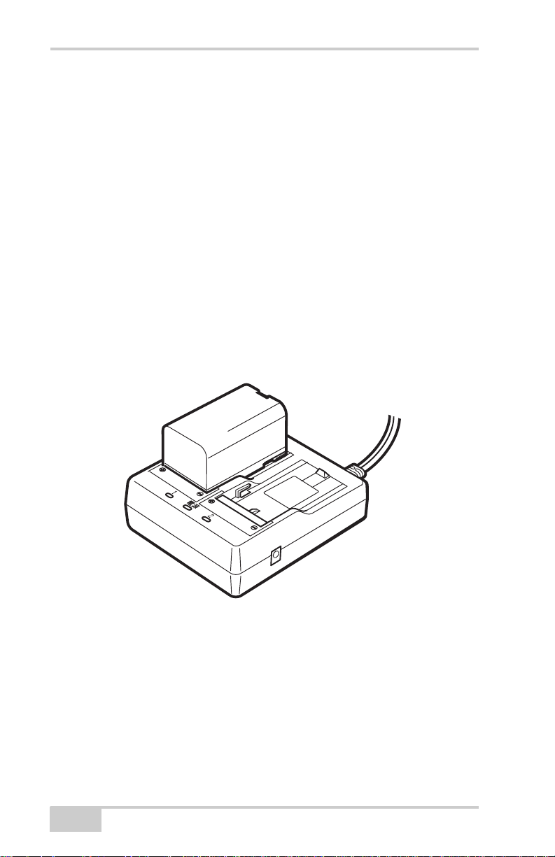
Battery
The HiPer II receiver comes equipped with two detachable Li-Ion
batteries (Figure 1-2) for powering the receiver and one CDC68
charger.
The battery is capable of running for more than 7.5 hours on a single
charge (only static observation).
The battery compartment door provides access to the main battery.
The receiver can also be powered using an external power source.
Use one BDC58 rechargeable battery at a time to power the receiver.
The HiPer II also contains an internal backup battery, which
maintains an internal RTC. The backup battery is automatically
charged from the main battery.
1-10
Figure 1-2. HiPer II Battery and Charger
HiPer II Operator’s Manual
Page 25

Principles of Operation
Inserting and Removing the Battery
• First, before removing the battery, always turn off power to the
instrument. If the battery is removed while the power is switched
on, uncontrolled system shutdown will occur and file data may be
lost as a result.
• When inserting or removing the battery, make sure that moisture,
dust, or other foreign particles do not come in contact with the
inside of the instrument.
• Remove batteries from the surveying instrument or charger
before placing into storage.
• Store the battery in a dry room where the temperature is within
the following ranges. For long-term storage, the battery should be
charged at least once every six months.
Table 1-1. Battery Storage Time
Storage Period Temperature
1 week or less -20°C to +50°C
1 week to 1 month -20°C to +45°C
1 month to 6 months -20°C to +40°C
6 months to 1 year -20°C to +35°C
• The BDC58 uses the latest advances in high density lithium-ion
battery technology. However, like all batteries, it still generates
power using a chemical reaction and as a result, has a limited
lifetime. Even when the battery is in storage and not used for long
periods, the battery capacity deteriorates with the passage of time.
This may result in the operating time of the battery shortening
despite having been charged correctly. In this event, a new
battery is required.
P/N 7010-0982
1-11
Page 26
Introduction
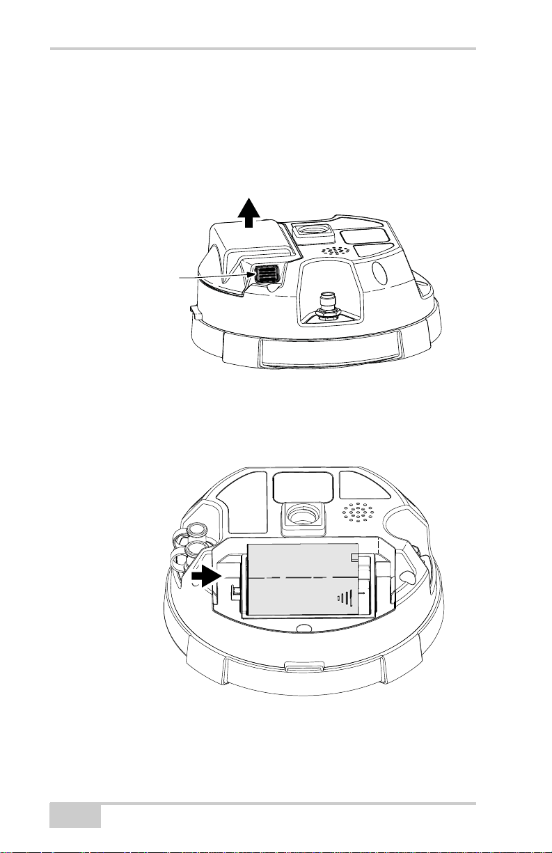
Press and Hold
Both Battery
Compartment Buttons
(One on Each Side)
Slide Battery
to the Right to
Remove
To Remove the Battery:
1. Turn the HiPer II over.
2. Push the battery buttons on both sides of the battery compartment
cover, and lift the battery cover.
Figure 1-3. Remove Battery Compartment Cover
3. Slide the battery to the right, and separate the battery from the
connector.
4. Lift up the battery, and remove it from the receiver.
1-12
Figure 1-4. Remove Battery
HiPer II Operator’s Manual
Page 27
Principles of Operation
NOTE
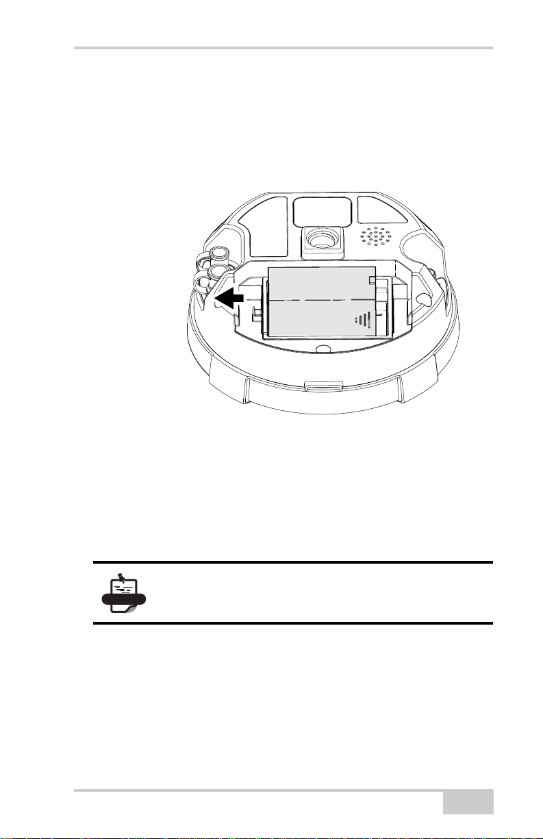
Slide Battery
to the Left to
Lock in Place
To Insert the Battery:
1. Remove the battery cover.
2. Gently slide the bottom of the battery along the battery guides
until it snaps into place (Figure 1-5 on page 1-13).
Figure 1-5. Remove Battery Compartment Cover
Charging the Battery
To charge the battery, use the included charger. It takes
approximately 4 hours to completely charge one battery, and 8 hours
to completely charge two batteries.
The battery is shipped from the factory without
power. Fully charge the Battery before surveying.
The Li-Ion batteries used in the battery packs should run at no less
than 80% capacity after 500 charging cycles. These batteries do not
need to be drained before recharging.
It takes approximately 4 hours to completely charge one battery, and
8 hours to charge two batteries using the included CDC68 charger.
P/N 7010-0982
1-13
Page 28
Introduction
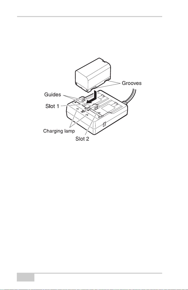
1. Connect the power cable to the charger and plug the charger into
the wall outlet.
2. Mount the battery in the charger by matching the grooves on the
battery with the guides on the charger.
Figure 1-6. Insert Battery onto Charger
3. When charging begins, the lamp light blinks.
4. The lamp light is solid when charging is complete.
1-14
HiPer II Operator’s Manual
Page 29
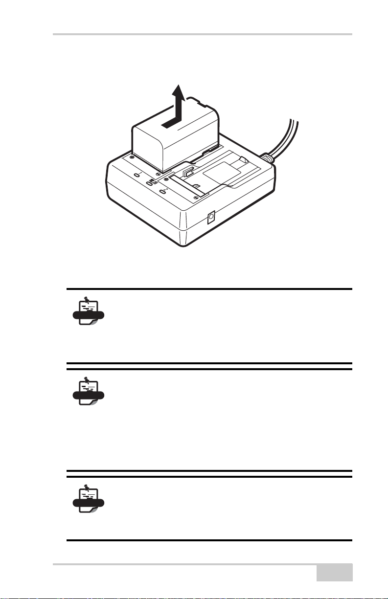
5. Remove the battery and unplug the charger.
NOTE
NOTE
NOTE
Figure 1-7. Remove Battery
Slots 1 and 2:
The charger starts charging the battery mounted
first. If two batteries are placed in the charger, the
battery in slot 1 is charged first, and then the battery
in slot 2.
Principles of Operation
P/N 7010-0982
Charging lamp:
• The charging lamp is off when the charger is
outside the charging temperature range or when
the battery is mounted incorrectly. If the lamp is
still off after the charger falls within its charging
temperature range and the battery is mounted
again, contact a local dealer.
Charging time per battery (at 25°C):
• BDC58: about 4 hours (Charging can take
longer than the times stated above when
temperatures are either especially high or low.)
1-15
Page 30
Introduction
Receiver
Health
Available Power Bar
Memory Capacity Bar
Wireless Status
Radio
Status
Serial Port
Status
File Status
Battery Status
Timer
Receiver
Health
Available Power Bar
Tracking Status (STAT)
Memory Capacity Bar
Wireless Status
Radio
Status
Serial Port
Status
File Status
Position Status Bar
Battery Status
Power
Button
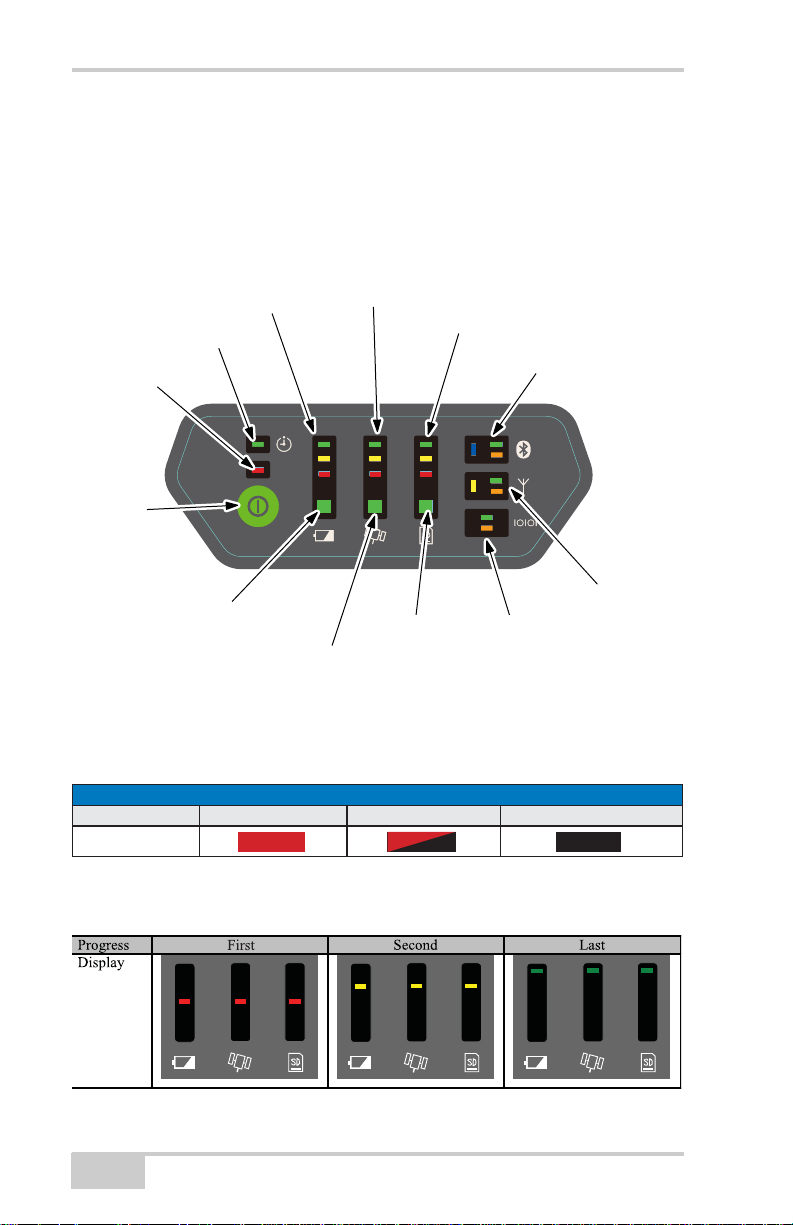
LED Display Panel
The HiPer II LED Display Panel is used to display and indicate the
receiver’s current operational status. The display offers a compact but
valuable summary of the most important receiver information for the
typical user.
The LED display table below describes the meaning of the LED icons
used in this section.
LED ICON KEY
DISPLAY SOLID BLINKING DARK
Boot During the boot process the display indicates boot progress.
1-16
Figure 1-8. HiPer II LED Display Panel
HiPer II Operator’s Manual
Page 31

Principles of Operation
AVAILABLE POWER BAR
DISPLAY INTERNAL POWER REMAINING EXTERNAL POWER REMAINING
Greater than 50%
Greater than 25%
Greater than 10%
Less than 10%
Greater than 8V
Greater than 7.25V
Greater than 6.5V
Less than 6.5V
POSITIONING STATUS BAR
R7.¿[HGVROXWLRQ
'*36RUR7.ÀRDWVROXWLRQ
6WDQGDORQHRUEDVHPRGH
,QYDOLGRUQRSRVLWLRQ
Available Power Bar indicates the remaining battery charge or
remaining voltage when using external power.
Battery Status LED indicates the currently available power sources
for the HiPer II.
BATTERY STATUS
Only the internal battery is available.
Only external power is available.
Both the battery and external power are available.
Position Status Bar indicates the current type of position computed.
P/N 7010-0982
1-17
Page 32

Introduction
TRACKING STATUS (STAT)
ORDER DISPLAY STATUS
1 Blink per tracked GPS satellite.
2 Blink per GPS satellite with <48dB signal strength.
3 Blink per tracked GLONASS satellite.
4
Blinks once when no satellites or no solution.
Dark otherwise.
STAT LED indicates the number and type of satellites currently being
tracked by the HiPer II.
Memory Capacity Bar indicates the percentage of available space on
the SD/SDHC memory card.
MEMORY CAPACITY BAR
Greater than 50%
Less than 50%
Less than 25%
Less than 10%
Memory full or SD/SDHC card is not ready.
No card is installed.
1-18
HiPer II Operator’s Manual
Page 33

Principles of Operation
FILE STATUS
A¿OHLVRSHQ
WULWLQJWRWKH¿OH
A¿OHLVQRWRSHQRUWKHUHLVQR6'6'+&FDUGLQWKHVORW
COMMUNICATION STATUS (WIRELESS/RADIO/SERIAL PORT)
Bluetooth connection is established.
Waiting for Bluetooth connection.
Bluetooth module is not powered.
Internal radio is powered.
Internal radio is not powered.
Data is being transmitted from the associated port.
Data is being received by the associated port.
File Status LED indicates the status of the current file.
Communication Status LEDs
Wireless Status LEDs indicate the status of the internal
Bluetooth module.
Radio Status LEDs indicate the status of the internal UHF
radio and GSM module.
Serial Port Status LEDs indicate the status of the serial port.
P/N 7010-0982
1-19
Page 34

Introduction
TIMER STATUS
A Timer JOB has started and is waiting to begin file operations.
The file is opened by the JOB.
The file is closed by the JOB.
POWER BUTTON FUNCTIONS
ACTION SECONDS DESCRIPTION
Power ON
Press for 1
second
The HiPer II powers ON.
Power OFF
Press for 3
seconds
The HiPer II powers OFF.
WITH POWER ON
Factory Reset
Press for 10
seconds
Resets all parameters on the
HiPer II to their default values.
Erase Memory
Press for 20
seconds
'HOHWHVDOO¿OHVIURPWKH6'6'+&FDUG
Disregard
Press for
more than 25
seconds
No action. The HiPer II will return to
normal operation.
6WDUW6WRSUHFRUGLQJ
UDZGDWDWRWKH6'
6'+&FDUG
Press 3 times
in a row
6WDUWDUDZFROOHFWLRQWRDQHZ¿OHRU
FORVHDFXUUHQWO\RSHQ¿OH
Timer LED indicates the state of the timer.
When the HiPer II is powered off and a timer JOB is in waiting,
the timer LED blinks once every two seconds momentarily.
Power Button performs multiple functions. The number of seconds
that the power button is pressed and held determines how the receiver
will behave. At specific time intervals, the receiver issues voice
messages or sounds to guide the user through the available options.
Figure 1-9 on page 1-21 further describes the power button presses
necessary to start/stop raw data recording to the SD/SDHC card.
1-20
HiPer II Operator’s Manual
Page 35

Principles of Operation
NOTE
Figure 1-9. Raw Data Collection using the Power Button
Audible Annunciator
The HiPer II receiver is equipped with a voice notification feature
that issues a series of voice messages and sounds to alert the user to
different system status’ and event conditions.
The HiPer II is preconfigured with either voice
messages or sounds at a preset volume. To modify
these settings, use the TRU software or other
application software.
The frequency of the voice messages or sounds depends on the
specific conditions; the frequency is either once (when the condition
first occurs) or repeated (every 30 seconds for a set period of time).
P/N 7010-0982
1-21
Page 36

Introduction
AUDIO EVENT INDEX
N EVENT NAME DESCRIPTION
LOGEPOCH
STARTUP
SHUTDOWN
BTNPOWER
BTNFRESET
BTNFORMAT
BTNIGNORE
BATTLOW
MEMLOW
MEMFULL
RTKFIXED
RTKFIXLOST
CONNECT
DISCONNECT
Message recorded to file
System has completed startup
Receiver is shutting down (immediate)
Power Button – Power Off
Power Button – Factory Reset
Power Button – SD Format
Power Button – Return to normal operation
Battery power is low
Remaining space on SD memory card is low
SD memory card is full
RTK solution is now Fixed
RTK solution is no longer Fixed
Bluetooth has been connected
Bluetooth has been disconnected
1
2
3
4
5
6
7
8
9
10
11
12
13
14
The following events generate messages from the HiPer II audible
annunciator:
Data and Power Ports
The HiPer II has the two ports described below (Figure 1-10 on
page 1-23):
• Serial - rimmed in black; used for communication between
the receiver and an external device. The body of the
connector on the corresponding cable is black.
• Power - rimmed in red; used to connect the receiver to an
external power source. The body of the connector on the
corresponding cable is red.
1-22
HiPer II Operator’s Manual
Page 37

Principles of Operation
Antenna
Port
Power
Port
Serial
Port
Antenna
Port
Figure 1-10. HiPer II Ports
External Radio Antenna Connector
The antennas for the receiver’s internal UHF radio (and optional
cellular modem) connect to the BNC external antenna connector
located under the HiPer II housing (Figure 1-11).
The optimal modem antenna depends on the frequency of the UHF
radio that is installed in the receiver:
• UHF: Uses a BNC RF connection and comes in two versions:
– 410-440Hz (30-070003-01)
– 440-470Hz (30-050503-01)
Figure 1-11. Modem Antenna
P/N 7010-0982
1-23
Page 38
Introduction
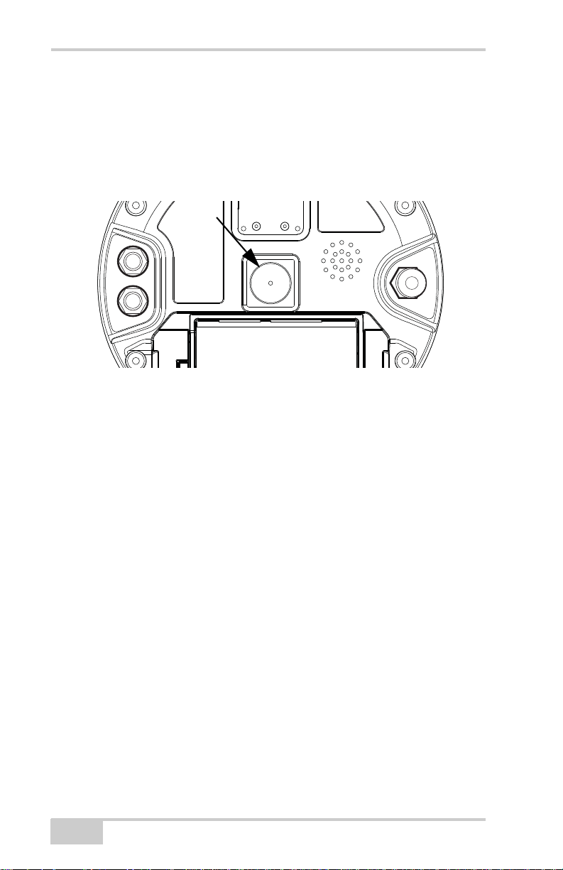
Bottom Connector
Connector
The bottom connector (Figure 1-12) connects the receiver to either a
standard 5/8'' thread pole or adapter.
Figure 1-12. HiPer II Bottom Connector
SD/SDHC and SIM Card Slots
The SD/SDHC and SIM card slots reside under the battery on the
inside edge of the battery recess.
The SD/SDHC card slot is located inside the battery recess
(Figure 1-13). Once inserted, the SD/SDHC card can be installed or
removed from the receiver by pushing the card in until it locks, then
pushing the card once more to remove it. The data that resides on the
SD/SDHC card can be accessed by removing the card and using an
external SD/SDHC card reader, or by using Topcon PC software to
download the data from the card via HiPer II’s serial port or
Bluetooth connection. A secure digital card suitable for industrial use
can be purchased from a local Topcon dealer. The SD/SDHC card is
available in FAT16 or FAT32 format so that the removable SD/
SDHC card is suitable for copying data files directly to a PC.
The SIM card slot is located inside the battery recess and allows a
standard SIM card to be inserted into the receiver. Once inserted, the
SIM card provides a unique identification for the receiver’s GSM
cellular module and enables the receiver’s GSM functionality based
1-24
HiPer II Operator’s Manual
Page 39

Principles of Operation
on the user’s subscribed cellular network services (the receiver board
accesses the GSM module which accesses the SIM card). The SIM
card usually remains inside the receiver. Details for the installed SIM
card can be accessed via TRU for configuration purposes. A SIM card
is typically supplied from a local cellular provider at the time of
network subscription.
SIM Card Slot
SD/SDHC Card Slot
Figure 1-13. HiPer II Card Slot Example
Once installed, the card(s) generally remains installed. The card can
then be accessed via the receiver board using a data port or Bluetooth
connection.
To install the SD/SDHC card (Figure 1-14):
1. Ensure the receiver is turned off.
2. Remove the battery. See “To Remove the Battery:” on page 1-12.
P/N 7010-0982
1-25
Page 40

Introduction
CAUTION
NOTICE
3. Carefully insert the SD/SDHC card, label side down, into the SD/
SDHC card slot located at the top of the battery recess.
Figure 1-14. Install SD/SDHC Card
Do not remove the card if the receiver is powered
on. Damage to data may result from improper
removal of the card.
Once the receiver is turned on, the receiver board will detect the SD/
SDHC card, and it will be ready to use as needed.
To install the SIM card (Figure 1-15):
The SIM card must support Circuit Switched Data to communicate
directly between receivers. The SIM card must have GPRS or EDGE
support to communicate with a GPS Network IP address.
For direct communication between Base and Rover
receivers, the user must install a SIM card with a
Circuit Switch Data plan and have subscriptions to
the same service provider for proper data
communication.
1. Ensure the receiver is turned off.
2. Remove the battery.
3. If needed, snap the SIM card into its holder.
1-26
HiPer II Operator’s Manual
Page 41

Principles of Operation
4. Carefully insert the holder, label side down, into the SIM card
slot located at the top of the battery recess.
Figure 1-15. Install SIM Card
Once the receiver is turned on, the receiver board will detect the SIM
card, and it will be ready to use as needed.
Serial Cable
The HiPer II package includes a serial communication cable for
configuring the receiver. Table 1-2 describes the cable included in the
HiPer II package.
Table 1-2. HiPer II Serial Cable
Cable Description Cable Illustration
Serial cable
Connects the receiver to an external
device (controller or computer) for
data transfer and receiver
configuration.
p/n 14-008005-03
P/N 7010-0982
1-27
Page 42

Introduction
Other Accessories
• Battery (BDC58) Li-ion Battery (4,300mAh, 7.2 VDC) x 2
• Battery Charger (CDC68)
• Power Cable (73113/A/B/C) from CDC68 to AC power outlet or
plug (region specific)
•Manual CD
• GPS+ Software CD
For additional details on the accessories and package options
available for the HiPer II, contact a local Topcon dealer.
Optional Accessories
Topcon offers a wide variety of accessories especially designed to
improve system flexibility and jobsite efficiency. For more details on
the optional accessories available for HiPer II, contact a local Topcon
dealer.
• Radio Antenna for Digital modem 410-470Hz (30-070003-01 or
30-050503-01)
• 10cm spacer for tripod operation
• SD Card industrial model
• Measuring Tape (22-050902-1) 3.7m HI (Calibrated)
1-28
HiPer II Operator’s Manual
Page 43

Option Authorization File (OAF)
Option Authorization File (OAF)
Topcon issues an Option Authorization File (OAF) to enable the
specific options that customers purchase. Topcon’s OAF system
allows customers to customize and configure the receiver according
to their particular needs, thus only purchasing those options they
really need.
Receivers typically ship with a temporary OAF that allow them to be
used for a predetermined period of time. When the receiver is
purchased, a new OAF permanently activates purchased options.
Receiver options remain intact when clearing the NVRAM or
resetting the receiver.
The OAF enables the following kinds of functions. For a complete list
of available options and details for HiPer II, visit the Topcon website
or consult a Topcon dealer.
• Type of signal (standard L1 GPS; optional L2, GPS,
GLONASS)
• Update rate standard 1Hz (optional 5, 10, 20Hz)
• RTK at 1Hz, 5Hz, 10Hz, and 20Hz
• RTK base operation (message output)
• Advanced Multipath Reduction (AMR)
• Receiver Autonomous Integrity Monitoring (RAIM)
P/N 7010-0982
1-29
Page 44

Introduction
Notes:
1-30
HiPer II Operator’s Manual
Page 45

Chapter 2
Pre-survey Preparation
Before beginning to survey with the HiPer II receiver, install the
following software, charge the battery, and apply the following
configurations:
Install receiver configuration software
See “Installing Topcon Software” on page 2-2.
Optional: install SD/SDHC card and/or SIM card
See “Install the Optional SD/SDHC and SIM Cards” on page 2-3.
Charge the Battery
See “Charge and Insert the Battery” on page 2-3.
Configure the Bluetooth wireless technology module
See “Establishing a Wireless Connection” on page 2-5.
Collect almanacs and ephemerides (after first-time configuration
activities as described in Chapter 3)
See “Collecting Almanacs and Ephemerides” on page 2-7.
This chapter also discusses connecting the receiver to a computer.
P/N 7010-0982
2-1
Page 46

Pre-survey Preparation
Installing Topcon Software
The GPS+ Software CD includes the TRU (Topcon Receiver Utility)
software. If installing TRU from the GPS+ Software CD, insert the
CD into the computer’s CD/DVD-ROM drive. If downloading TRU
from the website, extract the program’s files into a folder on the hard
drive.
The following sections describe installing this software, and other
sections throughout the manual describe using this software with the
HiPer II receiver.
Installing TRU
TRU is a Windows® software application designed for configuring
GNSS receivers.
Computer requirements for TRU are: Microsoft® Windows XP/
Vista/7 operating system and an RS-232C port or computer with
Bluetooth wireless technology. Use TRU to correctly configure the
receiver.
To install TRU:
1. Navigate to the TRU folder, and double-click TRU.zip.
2. Extract TRU.exe to the TRU folder.
3. Double-click TRU.exe to run the installer, and then follow the
on-screen instructions.
After installation, shortcuts appear on the desktop and in the TRU
menu.
Figure 2-1. TRU Desktop Shortcut
2-2
HiPer II Operator’s Manual
Page 47

Install the Optional SD/SDHC and SIM Cards
NOTICE
NOTICE
Install the Optional
SD/SDHC and SIM Cards
Ensure the optional SD/SDHC and SIM cards are
installed, if required. See “SD/SDHC and SIM Card
Slots” on page 1-24.
Charge and Insert the Battery
Ensure the is fully charged and inserted into the
HiPer II’s battery recess. See “Inserting and
Removing the Battery” on page 1-11.
Connecting to the Receiver using TRU
TRU provides an interface for various configuration, monitoring, and
management functions for the receiver.
To configure, manage files, or maintain the receiver, launch TRU on
a computer or data collector and connect to the receiver using one of
the following methods:
• a Bluetooth-enabled external device (computer/controller)
• an RS232 cable and a computer/controller
Once a connection between the receiver and the computer/controller
has been established, the user is able to configure the receiver and its
components, send commands to the receiver, download files from the
receiver’s memory, upload new firmware, and upload an OAF.
P/N 7010-0982
2-3
Page 48

Pre-survey Preparation
Establishing a Serial Cable Connection
To establish a connection to a receiver, take the following steps:
1. Press the power buttons on the receiver to turn it on.
2. Using the provided serial cable (Table 1-2 on page 1-27), connect
the serial port of the computer (usually COM1) to the receiver’s
serial port.
3. Run TRU.
4. Click DeviceApplication mode and select Receiver
Managing mode.
5. Click DeviceConnect. The Connection Parameters dialog box
displays. To establish a connection to the receiver, press the
Connect button. When detecting the receiver, the Detecting
Receiver dialog box displays.
Figure 2-2. Stages for Connecting the Receiver via Serial Cable
6. To close the serial connection to the receiver, click
DeviceDisconnect:
2-4
HiPer II Operator’s Manual
Page 49
Connecting to the Receiver using TRU
NOTE
To successfully connect to the HiPer II receiver, do
not check the External Receiver checkbox in the
Connection Parameters dialog box.
Establishing a Wireless Connection
The HiPer II receiver contains Bluetooth wireless technology that
allows file transfer and synchronization between the receiver and any
other external device that supports Bluetooth wireless technology; for
example, an FC-250 controller, or a computer with integrated
Bluetooth support or a Bluetooth adapter installed.
Before establishing a connection to the receiver via Bluetooth, make
sure the receiver’s Bluetooth module is powered (Wireless Status
LED blinks blue). If this LED does not blink, the receiver Bluetooth
module must first be activated. To do so, first connect to the receiver
using the serial cable (follow the steps 1-5 described in “Establishing
a Serial Cable Connection” on page 2-4).
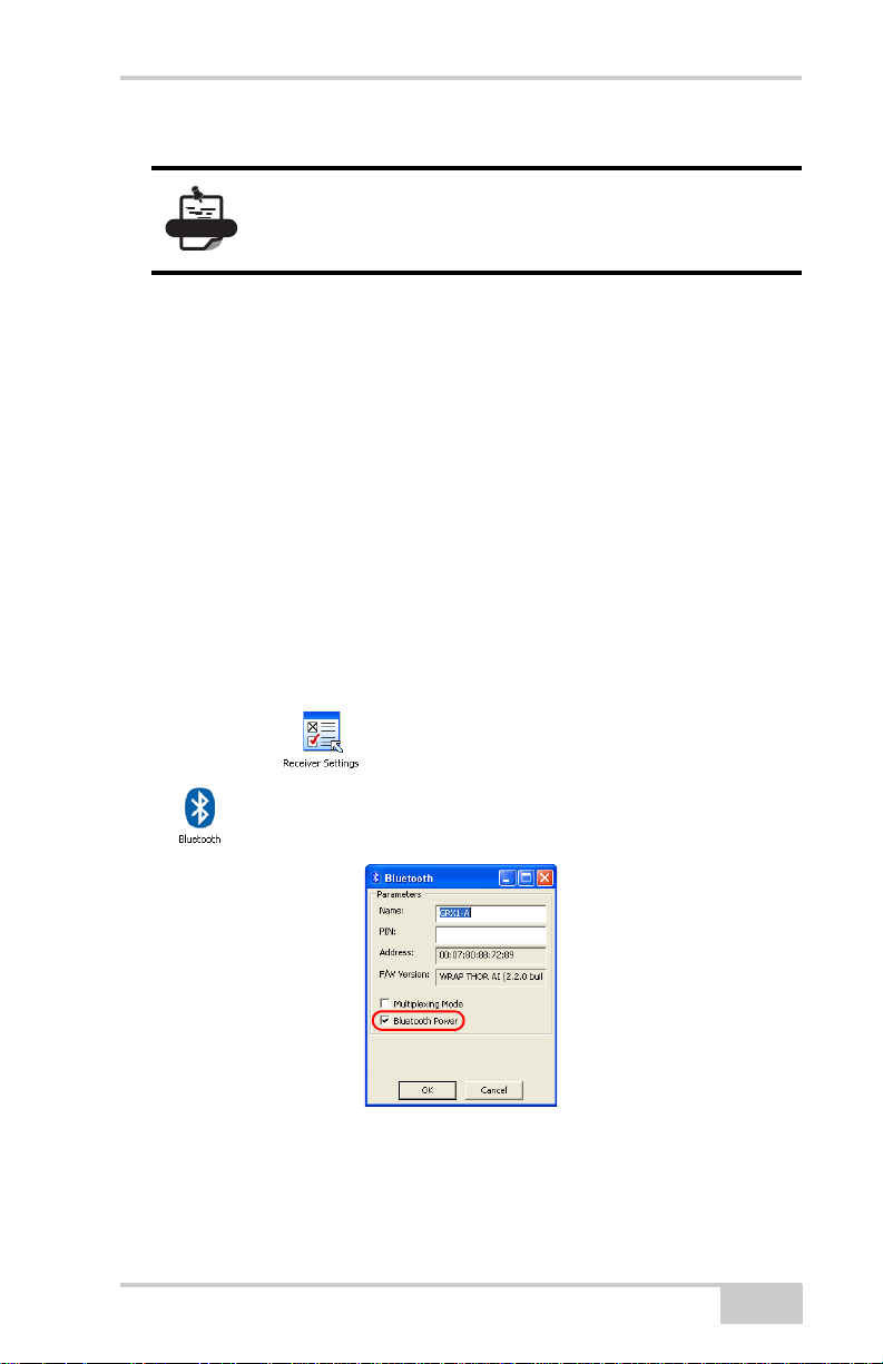
Then click the icon in the main window, and then click
the icon. The Bluetooth dialog box displays:
Check the Bluetooth Power check box. Clicking OK will activate the
receiver Bluetooth module. Wireless Status LEDs will blink blue.
P/N 7010-0982
2-5
Page 50

Pre-survey Preparation
Close the connection between a receiver and computer/controller via
RS-232 cable (see step 6 described in “Establishing a Serial Cable
Connection” on page 2-4).
To establish a connection to the receiver via Bluetooth, take the
following steps:
1. Press the power button on the receiver to turn it on.
2. Run TRU.
3. Click DeviceApplication mode and select Receiver
Managing mode.
4. Click DeviceConnect. The Connection Parameters dialog box
displays. To establish a Bluetooth connection select Bluetooth in
the Connect Using field and click button to search the
devices with Bluetooth.
Figure 2-3. Searching Bluetooth Devices
5. After finishing the search of Bluetooth-enabled devices, select the
desired receiver in the Select Port dialog box and click OK. To
establish the connection to the receiver, press the Connect button
in the Connection Parameters dialog box. When detecting the
receiver, the Detecting Receiver dialog box displays (Figure 2-4
on page 2-7).
2-6
HiPer II Operator’s Manual
Page 51

Collecting Almanacs and Ephemerides
Figure 2-4. Stages for Connecting to the Receiver via Bluetooth
6. To close the connection to the receiver, click
DeviceDisconnect:
Collecting Almanacs and
Ephemerides
Each satellite broadcasts a navigation message that includes the
ephemeris parameters of the satellite, the almanac, and various other
information. The ephemeris parameters describe the orbital motion of
the tracked satellite and are used to predict its location/trajectory. The
almanac gives the approximate orbit (course) for the transmitting
satellite as well as all other satellites in the same system.
• GPS and GLONASS satellites broadcast ephemeris data
cyclically, with a period of 30 seconds.
• GPS satellites broadcast almanac data cyclically with a period of
12.5 minutes; GLONASS satellites broadcast almanac data
cyclically with a period of 2.5 minutes.
If the receiver has an almanac, the time needed to search for and lock
onto satellite signals is considerably reduced.
P/N 7010-0982
2-7
Page 52

Pre-survey Preparation
NOTICE
The receiver regularly updates the almanac and ephemerides and
stores the most recent versions in its Non-Volatile Random Access
Memory (NVRAM).
Perform the following to collect Alamac and Ephemerides data:
1. Set up the receiver in a location with a clear view of the sky.
2. Turn on the receiver.
3. Wait for about 15 minutes while the receiver collects complete
almanac and ephemeris data from the satellites.
If 15 minutes have passed and the receiver does not
lock onto satellites, clear the NVRAM. See “Using
TRU to Clear the NVRAM” on page 5-9 for details.
The almanac and ephemerides will need to be collected or updated
under the following circumstances:
• If the receiver has been off for a long time.
• If the last known receiver position, stored in the NVRAM, is
different from the present position by several hundred kilometers.
• After loading a new OAF.
• After loading new firmware.
• After clearing the NVRAM.
POWERUP Script
The HiPer II’s POWERUP script feature uses specially formatted
ASCII text file (GRIL commands) that, once installed, enables the receiver
to perform a series of custom operations simply by pressing the
power button to turn on the receiver. i.e.:
• Automatically start static data logging to the SD/SDHC card.
• Automatically begin message output to the serial port.
• Automatically configure and start the RTK UHF Base radio.
2-8
HiPer II Operator’s Manual
Page 53

POWERUP Script
Example
An example of an easy “one button” base setup that is supported
using the POWERUP script would be to:
– Mount the receiver on a tripod and press the power button
– During RTK base operation, the receiver will also
automatically collect raw measurement data to the SD/SDHC
card.
– The receiver will automatically compute an averaged single-
point RTK base position.
After pressing the power button, the operator may simply walk away.
No cabling, external data link, or data collector is required; work on
site can begin almost immediately.
POWERUP Script Requirements
After turning on the HiPer II receiver, the POWERUP script executes
when the receiver obtains valid position coordinates and the
following requirements are satisfied.
• The POWERUP script has been installed to receiver.
• The POWERUP script function setting is ON.
• The receiver is not starting by using the timer.
• There is no enabled session timer.
Installing the POWERUP Script
To install the POWERUP script onto the HiPer II receiver:
1. Copy the POWERUP script file “powerup.gcs” to the
“POWERUP” folder on the SD card.
2. Insert the SD card into HiPer II receiver.
3. Perform a Factory Reset on the HiPer II.
P/N 7010-0982
2-9
Page 54

Pre-survey Preparation
NOTICE
4. Once the installation is successful, the “powerup.gcs” file is
removed from the SD card.
If the file attribution is Read only, the file will not
be not removed.
If there is the existing POWERUP script on the
HiPer II, it will be overwritten by the new script
file.
Uninstalling the POWERUP script
The POWERUP script can be uninstalled by using either of the
following two methods.
Method 1: Install an empty (no script) “powerup.gcs” file.
Method 2: Send the command “set,/ext/powerup/clear,y” using the
Terminal feature of TRU.
Editing the POWERUP Script
It is not possible to edit the existing POWERUP script in receiver
directly. Install (overwrite) the new POWERUP script after
modifying the script using TRU.
Enabling the POWERUP Script
It is necessary to enable the POWERUP script function in order to
allow the HiPer II to execute the POWERUP script at every startup of
the receiver. Enable the POWERUP script by using any of the
following three methods.
Method 1: Send the terminal command “set,/ext/powerup/mode,on”
Method 2: Perform a Factory Reset of the receiver.
Method 3: Enable using the TRU software.
2-10
HiPer II Operator’s Manual
Page 55

POWERUP Script
Disabling POWERUP Script
Disable the POWERUP script by using either of the following two
methods.
Method 1: Send the terminal command “set,/ext/powerup/mode,off”
Method 2: Disable by using the TRU software.
P/N 7010-0982
2-11
Page 56

Pre-survey Preparation
Notes:
2-12
HiPer II Operator’s Manual
Page 57

Chapter 3
HiPer II Configuration
Both Base and Rover receivers can be configured according to the
survey methods that will be applied in the field.
When configuring receivers for RTK surveying, use the following
checklist to ensure the receivers are properly set up.
Perform pre-survey functions as described in Chapter 2.
Configure one receiver as an RTK Base station and the other
receiver as an RTK Rover. See “Configuring the Receiver” on
page 3-7.
• For a UHF Modem see “Configuring a Digital UHF Radio
Modem ” on page 3-4:
Set up the Base receiver over a known point to begin collecting
static observation data and transmitting RTK corrections. Set up
the Rover receiver to begin collecting RTK data. See “HiPer II
Receiver Setup” on page 4-1 for more information.
When configuring receivers for post-processing surveying, use
the following checklist to ensure the receivers are properly set up.
Perform pre-survey functions as described in Chapter 2.
Configure one receiver as a Base station and the other receiver as
a Rover. See “Configuring the Receiver” on page 3-7.
Set up the Base receiver over a known point to begin collecting
static observation data. Set up the Rover receiver to begin
collecting static or kinematic observation data. See “HiPer II
Receiver Setup” on page 4-1 for more information.
P/N 7010-0982
3-1
Page 58

HiPer II Configuration
Managing the Radio Modem
Topcon’s TRU software supports the configuration of all radio
modems that are embedded in Topcon receivers.
To configure the radio modem, have the following ready:
• PC running Windows 2000 or newer
•TRU
• A Serial cable or a Bluetooth-capable PC.
Connecting with the Radio Modem
1. Turn on the receiver. Connect the computer and receiver using an
RS-232 cable or Bluetooth wireless technology.
2. Open TRU. Click Device Application Mode Modem
Managing. Then click Device Connect.
Figure 3-1. Modem Managing
3. Select the COM Port of the computer to which the receiver is
connected.
3-2
HiPer II Operator’s Manual
Page 59

Managing the Radio Modem
4. Select the COM Port the receiver is connected to. Click OK.
Figure 3-2. Select COM Port
5. All internal modems for the HiPer II are on port C. Select the
Internal Modem check box and choose ser/c from the drop-down
menu. Click Connect.
P/N 7010-0982
Figure 3-3. Connection Parameters
3-3
Page 60

HiPer II Configuration
NOTICE
6. TRU will search through port speeds and flow settings until it
finds the modem.
Figure 3-4. Detecting Modem
When the modem is found TRU will return to the main screen.
Configuring a Digital UHF Radio Modem
To comply with RF exposure requirements,
maintain at least 25cm between the user and the
radio modem.
1. On the TRU Main Screen in Modem Managing mode double-
click on the Settings icon to configure the HiPer II internal
modem.
3-4
Figure 3-5. Modem Managing
HiPer II Operator’s Manual
Page 61

Managing the Radio Modem
2. If the user has a Digital UHF modem (other name Digital
AW401), this screen will appear as the General tab to show
information on the modem model, and the product identification
Figure 3-6. Modem General Information
3. Click on the Settings tab to open a list of settings of the modem
(see Figure 3-7 on page 3-5). The settings list varies depending
on the modem model and possibly the firmware version.
The settings can be read-only (marked by the icon) or
changeable (marked by the icon).
P/N 7010-0982
Figure 3-7. UHF Modem Settings
3-5
Page 62

HiPer II Configuration
• Mode – displays whether the UHF or GSM/CDMA band is used
for communication.
Baud rate – select a baud rate for the modem’s serial port. The user
can adjust the baud rate. This is the flow rate on the serial port
connecting the modem to the GPS board. 38400 is the recommended
rate with this radio. Ensure that the baud rate selected here in TRU
matches the baud rate selected in TopSurv, this is critical to the well
functioning of the entire system.
• Flow Control – controls the flow of data between the receiver
and modem. Enables software/hardware flow control.
• Modulation – selects a modulation type for the base radio
modem. For most applications the recommended setting is
GMSK. Select either DBPSK if using the Simplex protocol or
GMSK if using Trimble or PDL.
• Protocol – sets the protocol for data transmission. Select Simplex
(GMSK proprietary protocol) to work with Digital UHF
compatible modems. Note that the same protocol must be used
for both the base and rover to communicate properly.
• Repeater – enables retransmission in the wireless cluster
(Simplex only).
• Power – sets the transmission power for the base radio modem
(from 10 mW to 1W).
• Space – sets the channel step.
• Channel – assigns an operating channel to the radio modem.
Each channel uses a unique communication frequency. Select the
desired frequency from the channel list.
Note that the same
channel must be used for both the base and rover to communicate
properly.
• Scrambler – provides more robust data communication over
high interference areas (must be used with GMSK).
• FEC – (Forward Error Correction) Enable to maximize data link
reliability. The rover radio modem has the capability to check and
correct transmission errors (if any) in an incoming data stream.
3-6
HiPer II Operator’s Manual
Page 63

Configuring the Receiver
Link Rate dependence on the modulation and the spacing value is
presented in Table 3-1.
Table 3-1. Link Rate vs. Modulation and Space Value
Modulation Space Values 12.5 kHz 25 kHz
DBPSK
(not recommended)
DQPSK Differential Quadrature
GMSK Minimal Shift Keying
4FSK Four Level Frequency
Differential Binary
Phase Shift Keying
Phase Shift Keying
with Gaussian Filtering
Shift Keying
4.8 kbps 9.6 kbps
9.6 kbps 19.2 kbps
4.8 kbps 9.6 kbps
9.6 kbps 19.2 kbps
When finished configuring the radio modem, always disconnect from
TRU before exiting to prevent conflicts with serial port management.
If needed, launch TRU and set up the receiver to run as an RTK Base
station or RTK Rover.
Configuring the Receiver
The HiPer II can be configured in several ways for collecting data for
RTK or post-processing.
• A static Base station collects measurement information and saves
this data to its internal memory.
• An RTK Base station collects measurement information,
determines differential corrections, and transmits them to the
RTK Rover(s).
• A static Rover collects observation data from the same satellites
during the same time interval as the static Base station.
• An RTK Rover collects measurement information and accepts
corrections from the RTK Base station to compute its relative
position.
To configure, manage files, or maintain the receiver, launch TRU on
a computer or data collector and connect to the receiver using one of
the following methods:
P/N 7010-0982
3-7
Page 64

HiPer II Configuration
WARNING
• a Bluetooth-enabled external device (computer)
• an RS232 cable
TRU is Topcon’s GNSS receiver configuration software. For more
information on any of the procedures in this section or on TRU, refer
to the TRU Reference Manual.
TRU configures the various parts of the receiver, saving the settings
in the receiver’s memory.
Once a connection is established between the receiver and the
computer, TRU can:
• configure the receiver and its components
• send commands to the receiver
• download files from the receiver’s memory
• load a new OAF and other configuration files to a receiver
The following Base and Rover configurations are recommended for
the most common applications; however, the user can select
configuration parameters as needed for a particular jobsite.
Do not make other changes without consulting the
TRU Reference Manual.
1. Connect the receiver and computer as described in “Connecting
to the Receiver using TRU” on page 2-3.
3-8
HiPer II Operator’s Manual
Page 65

Configuring the Receiver
Once a TRU connection with the receiver has been established,
the Tools become active (Figure 3-8).
Figure 3-8. TRU Connection Established
2. Select the Receiver Settings icon. Then use the Receiver Settings
icons to configure the connected receiver.
P/N 7010-0982
Figure 3-9. Receiver Settings
3-9
Page 66

HiPer II Configuration
3. Click the Tracking icon, and set the antenna type used with the
connected receiver (Figure 3-10).
Figure 3-10. Set Antenna Usage
4. Click the Observation tab, and set the Elevation mask to 15
degrees for satellites tracking and position computation
(Figure 3-11), also the PDOP mask for position computation,
then click OK.
Figure 3-11. Configure Receiver Positioning – Elevation Mask
5. Click the Advanced tab. Set the following parameters, and click
OK (Figure 3-12 on page 3-11).
3-10
HiPer II Operator’s Manual
Page 67

Configuring the Receiver
• Anti-jamming – if available for the connected receiver,
enables suppression of narrow-band interference for GPS,
GLONASS, L1, L2 signals, for auto-detected or manually
selected bands affected by interference.
• C/A code multipath reduction – when selected, enables the
use of a special signal processing technique for reduction of
C/A code phase multipath.
• C/A carrier phase multipath reduction – when selected,
enables the use of a special signal processing technique for
reduction of C/A carrier phase multipath.
• Cinderella – when selected, enables the Cinderella option
which sets all receiver options to their maximum allowable
values for 24 hours every other Tuesday at GPS midnight.
• Static Co-Op tracking – when selected, allows only the static
receiver to use satellites with lower signal-to-noise ratios.
Use only if the receiver’s antenna remains completely
stationary throughout the survey. Any movement may result
in losing the satellite lock.
Figure 3-12. Configure Advanced Parameters
6. For the Base receiver, click the Auto Seed icon, and set the
following parameters (Figure 3-13 on page 3-12), then click OK.
• Enable Auto Seed (not recommended for most survey users):
when selected, enables the Auto-Seed functionality for the
P/N 7010-0982
3-11
Page 68

HiPer II Configuration
base receiver. Auto-seed feature will provide users the ability
to quickly setup and begin RTK operations without using an
external interface to localize the base receiver. The user will
simply set up over a mark and power up. The base receiver
will automatically select a new position gathered by
autonomous averaging and save it for later re-occupation.
• Maximum distance: if the point has been previously
occupied and the receiver position falls within proper
tolerance, it will select a point from positions stored in
memory.
• Enable averaging mode: select to enable averaging
autonomous positions for a occupation point with the interval
set in the Position averaging interval field in seconds.
Figure 3-13. Base Configuration
• Click View the point list to open a list of previous occupations
saved in the receiver memory. This Auto Seed, Point List
contains information about all previous site occupations that are
stored in the receiver memory: names, date and time, coordinates
of phase center and/or antenna reference point, whether the point
was auto determined and protected from deleting. For details on
configuring the Auto Seed functionality, refer to the TRU
Reference Manual.
7. For the Rover receiver, click the Positioning icon, and set the
following parameters, then click OK (Figure 3-14 on page 3-13).
3-12
HiPer II Operator’s Manual
Page 69

Configuring the Receiver
• Positioning Mode – For post-processed surveys, select
Standalone; for RTK surveys, select RTK float or RTK fixed.
• Enable Solutions – Select solutions used in position
computation.
– Standalone – where the receiver computes 3D coordinates in
autonomous mode without using differential corrections.
– Code differential – where the Rover receiver computes the
current relative coordinate in differential mode using only
pseudo ranges.
– RTK float – where the Rover receiver computes the current
relative coordinates in differential mode using both pseudo
ranges and phases; however, with a float solution, the phase
ambiguity is not a fixed integer number and the “float”
estimate is used instead.
– RTK fixed – where the Rover receiver computes current
relative coordinates, with carrier phase ambiguity fixing in
differential mode.
Figure 3-14. Rover Configuration
8. For RTK surveys, click the Ports icon and set the required port
parameters for the serial port, then click OK (Figure 3-15 on
page 3-14).
P/N 7010-0982
3-13
Page 70

HiPer II Configuration
NOTICE
For post-processed surveys, keep the default values
for these parameters.
Figure 3-15. Ports Configuration
9. Click OK to save the settings and close the dialog box. Once the
receiver is configured, the configuration remains until it is
changed using TRU, TopSURV, or the NVRAM is cleared. For
more details on the settings available for configuring receivers,
refer to the TRU Reference Manual.
10. For RTK Rover receivers, click the Status icon (Figure 3-19 on
page 3-21) to ensure the receiver obtains differential corrections.
Usually, the receiver will start to output the coordinates of the
antenna’s phase center along with the solution type within 10–30
seconds. However, spread spectrum radios and GSM phones may
take as long as 60 seconds to synchronize.
The Data Link tab reflects the status of the received differential
messages and contains the following information:
• Data link quality in percentage
• Time (in seconds) elapsed since the last received message
• Total number of received correct messages (dependent on the
message type received)
3-14
HiPer II Operator’s Manual
Page 71

Configuring the Receiver
NOTICE
• Total number of received corrupt messages (dependent on the
message type received)
If the receiver is (for some reason) not receiving differential
corrections, or if none of the ports have been configured to
receive differential corrections, the Link Quality field will either
be empty or it will show 0%.
Figure 3-16. Status - Data Link
11. Continue with other configuration activities or click Device
Disconnect, then DeviceExit to quit TRU. Disconnecting
before exiting ensures proper port management.
Disconnect the receiver from TRU before exiting to
eliminate possible conflicts with the management of
the computer’s serial ports.
P/N 7010-0982
3-15
Page 72

HiPer II Configuration
Notes:
3-16
HiPer II Operator’s Manual
Page 73

Chapter 4
HiPer II Receiver Setup
After receiver survey configuration, set up each receiver, measure its
height, and begin surveying. The LED Display Panel provides quick
access for: logging data and viewing general data logging and
satellite information during a survey.
Receiver Setup
A typical GPS survey system consists of a Base station set up over a
known point and a Rover receiver set up as a mobile data collector.
After setting up the Base and Rover receivers, the antenna height
must be measured.
Before collecting data, make sure the Base and Rover receivers
contain a current almanac and current ephemeris data (see “Collecting
Almanacs and Ephemerides” on page 2-7).
Step 1: Set up the Receivers
The Base station must be set up, logging data, and transmitting data
before setting up the Rover receiver. Receiver setup for either postprocessing or RTK surveys is the same.
Set up the Base station and its components.
See “To set up the Base receiver” on page 4-1 for details.
Set up the Rover receiver.
See “To set up the Rover receiver” on page 4-3 for details.
To set up the Base receiver (Figure 4-1):
1. Install a tripod over a known control point.
2. Secure the universal tribrach onto the tripod. Place the tribrach
adapter onto the tribrach and tighten the screws.
P/N 7010-0982
4-1
Page 74
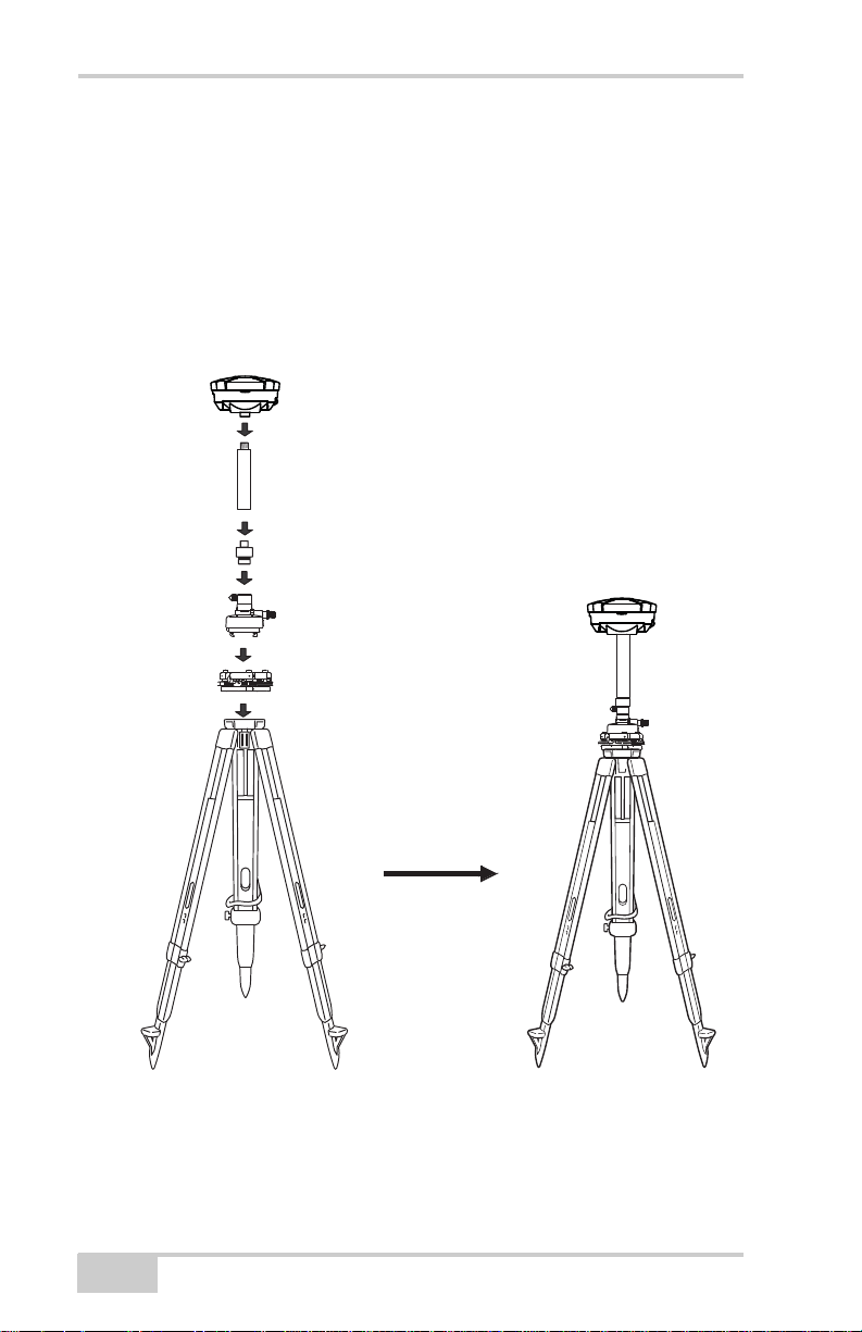
HiPer II Receiver Setup
HiPer II Receiver
Tribrach Adapter (Precision)
Universal Tribrach
Horizontal Spacer
10cm Spacer
3. Insert the horizontal spacer into the precision tribrach adapter.
4. Attach the 10cm spacer to the horizontal spacer.
5. Attach the HiPer II receiver to the 10cm spacer.
6. Attach the antenna to the antenna connector.
7. Carefully level the tripod and tighten the screws.
8. Attach any other accessories as needed (for example, a backup
power supply).
4-2
Figure 4-1. Install Tripod and Receiver over Control Point
HiPer II Operator’s Manual
Page 75

Receiver Setup
NOTICE
Lock
5/8 Inch Screw
HiPer II Receiver
To set up the Rover receiver (Figure 4-2 on page 4-3):
Use a bipod during post-process surveys to ensure
the antenna/receiver does not move during data
logging.
Attach the HiPer II receiver to the top of the rover pole with
5/8”x11” thread. Make sure that the receiver is securely affixed to the
top of the rover pole.
P/N 7010-0982
Figure 4-2. Connect HiPer II Receiver to Bipod
4-3
Page 76

HiPer II Receiver Setup
Step 2: Measure Antenna Height
The location of the antenna relative to the point being measured is
very important for both surveys in which the elevation of the points is
important and in surveys for horizontal location only. Horizontal
surveys are often larger in area than can reliably fit on a flat plane,
therefore the antenna adjustment must be done in three dimensions
and then projected onto a two dimensional plane.
The receiver calculates the coordinates of the antenna’s phase center.
To determine the coordinates of the station marker, specify the
following:
• Measured height of the antenna above the station marker
• Method of measuring the antenna height
• Model of the antenna used
Antennas have two types of measurements:
• Vertical – measured from the marker to the antenna reference
point (ARP) located on the bottom of the receiver at the base of
the mounting threads.
• Slant – measured from the marker to the lower edge of the
antenna slant height measure mark (SHMM) located on both end
panels of the receiver.
The surveying point that GPS/GLONASS to measure satellite
systems is called the “Phase Center” of the antenna. The antenna
Phase Center is analogous to the calibrated point to which a distance
meter measures inside of a prism; i.e. it cannot be directly measured
to in the field. For precision Topcon GPS/GLONASS antennas − such
as the one inside the HiPer II − the antenna Phase Center must be
modeled using a detailed calibration in order to achieved optimal
survey results. This model information consists of phase center offset
(PCO) and phase center variation (PCV) components, and is applied
internally by field software such as TopSURV for RTK operations,
and by Topcon Tools software for post-mission operations
1. This antenna calibration information (PCO and PCV data) does not
need to be entered in the field.
4-4
HiPer II Operator’s Manual
1
.
Page 77

Receiver Setup
The only information that must be supplied from field observations
when using Hiper II is i) the measured instrument height, and ii) the
measurement method used. The Topcon field and office software will
automatically make all antenna Phase Center adjustments
1
that are
necessary to deliver properly referenced marker coordinates.
1. Measure the antenna height above the control point or marker,
either the slant height or the vertical height.
You may either measure the vertical height to the Antenna
Reference Point (ARP) located at the bottom of the HiPer II, or
measure the slant height to the Slant Height Measurement Mark
(SHMM) on the side of the enclosure (Figure 4-3 on page 4-6).
2. Record the antenna height, points name, and start time in the field
notes.
1. Advanced users may choose to configure the applied Phase Center
model that is used for the Hiper II, and this may be done using Topcon
application software such as TopSURV and Topcon Tools. This
additional step is optional since Topcon software automatically contains
antenna Phase Center models for all Topcon products, including the
Hiper II.
Instead of Topcon's supplied default Phase Center model for HiPer II,
alternate or updated Phase Center models (with PCO and PCV data)
may be obtained from various government or private calibration
services. The most widely recognized of these services are the U.S.
National Geodetic Survey (NGS), the International GNSS Service
(IGS), and Geo++ GmbH of Germany. The default Phase Center
models supplied with Topcon products are typically based on absolute
calibration models from NGS.
P/N 7010-0982
4-5
Page 78

HiPer II Receiver Setup
LV LS
4-6
Figure 4-3. Antenna Height Measurement Points
HiPer II Operator’s Manual
Page 79

Static Surveying for Base Stations
Static Surveying for Base
Stations
Static surveying is the classic survey method, well suited for all kinds
of baselines (short, medium, long). At least two receiver antennas,
plumbed over survey marks, simultaneously collect raw data at each
end of a baseline during a certain period of time. These two receivers
track four or more common satellites, have a common data logging
rate (5–30 seconds), and the same elevation mask angles. The length
of the observation sessions can vary from a few minutes to several
hours. The optimal observation session length depends on the
surveyor’s experience as well as the following factors:
• The length of the baseline measured
• The number of satellites in view
• The satellite geometry (DOP)
• The antenna’s location
• The ionospheric activity level
• The types of receivers used
• The accuracy requirements
• The necessity of resolving carrier phase ambiguities
Generally, single-frequency receivers are used for baselines whose
lengths do not exceed 10 kilometers (approximately 6 miles). For
baselines of 10 kilometers or greater, use of dual-frequency receivers
is recommended.
Dual-frequency receivers have two major benefits. First, dualfrequency receivers can estimate and remove almost all ionospheric
effect from the code and carrier phase measurements, providing much
greater accuracy than single-frequency receivers over long baselines
or during ionospheric storms. Secondly, dual-frequency receivers
need less observation time to reach the required accuracy.
After the survey completes, data the receivers collect can be
downloaded onto a computer and processed using post-processing
software.
P/N 7010-0982
4-7
Page 80

HiPer II Receiver Setup
Notes:
4-8
HiPer II Operator’s Manual
Page 81

Chapter 5
Receiver and File Maintenance
When post-processing the data after completing a survey, the data in
the receiver’s memory needs to be downloaded to a computer.
Downloading and deleting files prepares the receiver’s memory for
the next survey. Occasionally, the receiver’s NVRAM may need to be
cleared to eliminate communication or tracking problems.
As project expectations expand, the receiver’s OAF may need to be
updated to provide expanded operation and functionality. The various
boards inside the receiver (GPS, power, modem, and Bluetooth)
require firmware to properly operate and provide appropriate
functionality. As Topcon releases firmware updates, loading these
updates into the receiver will ensure the receiver operates at its full
potential.
Downloading Files to a Computer
Downloading Files via TRU
TRU allows for downloading files to a computer and to also delete
files from the receiver.
1. Connect the receiver to a computer. Open TRU. See “Connecting
to the Receiver using TRU” on page 2-3 for this procedure.
P/N 7010-0982
5-1
Page 82

Receiver and File Maintenance
2. Click icon in the main window. The File Explorer dialog
box displays all logged raw data files (Figure 5-1).
Figure 5-1. File Explorer Dialog Window
3. To save a file to the computer, highlight the desired file, right
click and select Download from the pop up menu. In the Save As
dialog box navigate to or create a folder in which to download
and store the file (Figure 5-2). Click the Save button to download
and save the file.
5-2
Figure 5-2. Download a File
HiPer II Operator’s Manual
Page 83

Deleting Files from the Receiver Using TRU
4. When the process of transferring the file(s) from the receiver to
the computer begins, the Downloading window displays the
progress of the download.
Figure 5-3. Downloading in Progress
Deleting Files from the
Receiver Using TRU
To delete files from the receiver, perform steps 1and 2 described in
“Downloading Files to a Computer” on page 5-1. Then highlight a
desired file in the File Explorer dialog box, right click and select
Delete from the pop up menu. Click the Yes button to confirm of
deletion.
Figure 5-4. Deletion of a File
P/N 7010-0982
5-3
Page 84

Receiver and File Maintenance
Using the Power Button to Delete Files
All files stored on SD/SDHC card are deleted when the power button
is pressed for 20 seconds and released in less than 25 seconds (see
erase memory description in “Power Button” on page 1-20).
Managing Receiver Memory
When using the receiver in static or dynamic applications, the user
may need to know the amount of memory the receiver’s log file
occupies. The specific memory size depends on the type of data being
recorded. Use the formulas below to compute the approximate size of
the receiver’s log files. These equations are based on the default set of
messages.
• SS – the estimated size of one epoch of raw data in the receiver’s
log file (expressed in bytes).
• N – the number of observed satellites per epoch.
When recording only L1 data:
SS = 183 + 22*N
When recording L1 and L2 data:
SS = 230 + 44*N
Managing Receiver Options
The Option Authorization File (OAF) enables certain functions,
features, and options in the receiver, such as the following:
• The type of signal (L1, L1/L2, and so on) the receiver processes.
• The amount of data the receiver stores in the memory.
• The rate at which data is transmitted or received.
For a complete list of available options and details, consult with a
Topcon dealer.
5-4
HiPer II Operator’s Manual
Page 85

Managing Receiver Options
Checking the Receiver’s OAF
Use TRU to view the status of the receiver’s options.
1. Connect the receiver to a computer. Open TRU. See “Connecting
to the Receiver using TRU” on page 2-3 for this procedure.
2. Click icon in the main window. The Receiver Options
dialog box displays that allows the user to view the current
authorization options and upload new ones.
Figure 5-5. Receiver Options
Loading an OAF
Topcon dealers provide customers with OAF files. For any OAF
related questions, e-mail Topcon at
the receiver’s ID number (see the bottom of the receiver for the ID).
1. To load a new OAF, follow steps one and two in “Checking the
Receiver’s OAF” on page 5-5.
2. Click Upload OAF the bottom of the Receiver Options dialog
box (see Figure 5-5).
P/N 7010-0982
options@topcon.com and include
5-5
Page 86

Receiver and File Maintenance
3. Navigate to the location of the new Option Authorization File,
select the appropriate file and click Open (Figure 5-6).
Figure 5-6. Load OAF
4. Topcon TRU initially checks to see if the selected file is
compatible with the currently connected receiver. If the user
chose a file not intended for this receiver, the Upload OAF dialog
window displays an error icon next to the Receiver ID and
disables the Upload the File to the Receiver button
Figure 5-7. Compatibility Check of OAF
5. Press the Upload the File to the Receiver button to start loading
the file.
5-6
HiPer II Operator’s Manual
Page 87

Loading New Firmware
6. If an OAF file is uploaded to the receiver, the TRU will offer to
reset the receiver to put new authorization options into operation
(see Figure 5-8). Click the Yes button.
Figure 5-8. Reset the Receiver?
Loading New Firmware
Receiver board firmware is released as a compressed file that the user
download and decompress. This file contains the following two files:
• ramimage.ldr – the Receiver board RAM file
• main.ldp – the Receiver board Flash file
To upload firmware files to HiPer II receiver, follow the steps below:
1. Connect the receiver to a computer. Open TRU. See “Connecting
to the Receiver using TRU” on page 2-3 for this procedure.
2. Click icon in the main window. The Upload
Firmware dialog box displays. This dialog allows the user to
upload firmware files to the connected receiver.
3. Select “Receiver/modem” in the Device type field.
4. Set the Capture Method to “Soft Break” (recommended)
P/N 7010-0982
5-7
Page 88

Receiver and File Maintenance
5. Browse for and select the receiver board’s RAM file and Flash
file
Figure 5-9. Upload Firmware Dialog Box
6. Click Start to upload the selected files.
7. Click OK to complete uploading new firmware to the receiver.
Figure 5-10. Finishing Uploading Firmware
Clearing the NVRAM
The receiver’s Non-volatile Random Access Memory (NVRAM)
holds data required for satellite tracking, such as ephemeris data and
receiver position. The NVRAM also keeps the current receiver’s
settings, such as active antenna input, elevation masks and recording
interval, and information about the receiver’s internal file system.
Even though clearing the NVRAM is not a common (nor normally a
recommended) operation, there are times when clearing the NVRAM
5-8
HiPer II Operator’s Manual
Page 89

Clearing the NVRAM
can eliminate communication or tracking problems. Clearing the
receiver’s NVRAM can be interpreted as a “soft boot” in the
computer.
After clearing the NVRAM, the receiver requires time to collect new
ephemerides and almanacs (around 15 minutes).
Clearing the receiver’s NVRAM will not delete any files already
recorded in the receiver’s memory. However, it will reset the receiver
to factory default values.
In addition, the NVRAM keeps information about the receiver file
system.
Using TRU to Clear the NVRAM
1. Connect the receiver and computer. Open TRU. See “Connecting
to the Receiver using TRU” on page 2-3 for this procedure.
2. Click icon in the main window. The Tools dialog box
allows the user to reset the receiver and to clear the NVRAM
Figure 5-11. Tools Dialog Box
3. Click the Clear NVRAM button and click Yes button to continue
this procedure.
P/N 7010-0982
5-9
Page 90

Receiver and File Maintenance
Notes:
5-10
HiPer II Operator’s Manual
Page 91

Check This First!
WARNING
Troubleshooting
This chapter will help diagnose and solve some common problems
that may occur with the HiPer II.
Do not attempt to repair equipment yourself. Doing
so will void the warranty and may damage the
hardware.
Check This First!
Before contacting Topcon support, check the following:
• Check all external receiver connections carefully to ensure
correct and secure connections. Double check for worn or
defective cables.
• Check all power sources for a drained battery or incorrectly
connected battery/cables.
• Check that the most current software is downloaded onto the
computer and that the most current firmware is loaded into the
receiver. Check the Topcon website for the latest updates.
Then, try the following:
• Reset the receiver using TRU (ToolsReset receiver).
• Restore default settings using TRU (Configuration
Receiver, then click Set all parameters to defaults).
• Clear the NVRAM (see “Clearing the NVRAM” on page 5-8).
• Initialize the file system (click ToolsInitialize file system).
This will erase all files inside the SD/SDHC card in receiver.
If the problem persists, see the following sections for other solutions.
P/N 7010-0982
6-1
Page 92

Troubleshooting
Troubleshooting Quick List
For receiver power issues:
If “The receiver does not power up,” see page 6-3.
For receiver issues:
If “The receiver does not lock on to satellites for a long period of
time,” see page 6-4.
If “The receiver tracks too few satellites,” see page 6-5.
If “The receiver cannot obtain Code Differential and/or RTK
solutions,” see page 6-5.
If “The receiver does not start logging data,” see page 6-7.
For Bluetooth connection issues:
If “TRU error message: Can’t find receiver,” see page 6-8.
If “TRU error message: Open COM# port failed: Access is
denied,” see page 6-9.
If “TRU error message: Open COM# port failed: Access is
denied,” see page 6-9.
If “After searching for available devices, none are discovered,”
see page 6-9.
If “Can see the icon for the receiver’s Bluetooth module on the
computer screen, but cannot connect to it,” see page 6-10.
For modem issues:
If “TRU cannot connect to the receiver,” see page 6-10.
Powering Problems
All receivers are preset in the factory to “Auto mode” for the battery.
To check these settings, use the following procedure:
1. Connect the receiver and a computer and run TRU (see
“Connecting to the Receiver using TRU” on page 2-3).
2. Once connected, click ConfigurationReceiver.
6-2
HiPer II Operator’s Manual
Page 93

Powering Problems
TIP
3. On the General tab, view the Power and Charger fields. These
fields should be set to “Auto”. If not, change them to Auto and
click Apply.
Clearing the NVRAM returns the receiver to Auto
power mode (see “Clearing the NVRAM” on
page 5-8).
The receiver does not power up
D The attachable battery may be improperly attached.
• Check that the battery is correctly attached.
• Check that the battery contacts at the top of the attachable
battery are clean and dust free.
D The battery may be discharged.
• Connect/attach a fully charged battery and retry. See “Charge
and Insert the Battery” on page 2-3.
• Charge the battery overnight. See “Charge and Insert the
Battery” on page 2-3.
D If using an external power source, the cable may be
disconnected or damaged.
• Check that the cable is securely connected and undamaged.
D The receiver may have a defective charger or defective battery.
• If, after changing the battery or connecting an external power
source, the receiver still does not power up, contact Topcon
Customer Support for advice.
P/N 7010-0982
6-3
Page 94

Troubleshooting
Receiver Problems
The following are some of the most commonly encountered receiver
problems.
The receiver cannot establish a connection to a computer or
external controller
Cable specific problems:
D The cable is not properly plugged in.
• Check that the cable connector is attached to the correct
receiver port.
• Unplug the cable, then securely and properly reconnect it to
the receiver.
• See “HiPer II Features” on page 1-9 and “Power
Connector” on page A-12 for information on the receiver’s
connectors.
D The cable is damaged.
Use an undamaged cable. Contact a Dealer to replace the
cable.
Generic problems:
D The receiver port used for connection is not in Command mode.
1. Connect the receiver and a computer using a free port
(see “Connecting to the Receiver using TRU” on page 2-
3) and start TRU.
2. Click ConfigurationReceiverPorts.
3. Change the Input for the port used for connection to
“Command”.
The receiver does not lock on to satellites for a long period of
time
D The receiver stores an old almanac.
Update the almanac. See “Collecting Almanacs and
Ephemerides” on page 2-7 for details.
6-4
HiPer II Operator’s Manual
Page 95

Receiver Problems
D The corresponding receiver options may be disabled or expired
(L1/L2, GPS/GLONASS must be on to track satellites).
• See “Managing Receiver Options” on page 5-4 for details
on how to check current options.
• Order a new OAF with the desired options activated to
enable or extend validity of the corresponding receiver
options. Contact a dealer or visit the Topcon website for
details
• Refer to the TRU Reference Manual for a detailed
description of options.
The receiver tracks too few satellites
D The survey is conducted near obstructions (tree canopy, tall
buildings, and so forth).
• Check that the Multipath Reduction boxes have been
enabled.
1. Connect the receiver and a computer and start
TRU. See “Connecting to the Receiver using TRU”
on page 2-3.
2. Click ConfigurationAdvanced and the Multipath
Reduction tab. Enable the two boxes, and click
Apply.
• Move to an area free of obstructions, if applicable.
The receiver cannot obtain Code Differential and/or RTK
solutions
D Incorrect Base coordinates entered.
• Specify the correct coordinates for the Base station using
TRU or another suitable field data collection software.
D The receiver is not configured as a Base or Rover.
• If the receiver should function as a Base, ensure it has the
proper configuration. See Chapter 3 for details.
• If the receiver should function as a Rover, ensure it has the
proper configuration. See Chapter 3 for details.
P/N 7010-0982
6-5
Page 96

Troubleshooting
D The corresponding receiver options may be disabled or expired.
• See “Managing Receiver Options” on page 5-4 for details
on how to check current options.
• Order a new OAF with the required options activated to
enable or extend validity of the corresponding receiver
options. Contact a dealer or visit the Topcon website for
details
• Refer to the TRU Reference Manual for a detailed
description of options.
D There are not enough common satellites. In order to obtain a
fixed solution, the Base and Rover should track at least five
common satellites.
• Ensure that both the Rover and Base receivers use the
same, and updated, almanac. See “Collecting Almanacs
and Ephemerides” on page 2-7.
D A discrepancy exists between the differential standards used at
the Base and Rover receivers.
• Ensure the Base and Rover receivers use the same corrections
input/output format:
1. Connect the receiver and a computer and start TRU. See
“Connecting to the Receiver using TRU” on page 2-3.
2. Click ConfigurationReceiver and the Ports tab. Use
the same input/output format for both receivers.
D Poor satellite geometry (PDOP/GDOP values are too high).
• Conduct a survey when PDOP values are low.
D The modem battery is low.
D The transmitting and/or receiving antenna may be improperly
connected.
• Check that the radio modem’s antenna is securely and
properly connected to the antenna connector.
• Check that the radio modem’s antenna is undamaged. If
damaged, contact a Topcon dealer to replace the antenna.
6-6
HiPer II Operator’s Manual
Page 97

Receiver Problems
D The specified baud rate is incompatible with the baud rates the
modem supports. The baud rate is the rate at which the receiver
transmits differential messages to the modem and vice versa.
• Change the baud rate to that which the modem supports.
Refer to the modem’s manual for information.
D The Base and Rover modems use different radio link
parameters.
• Configure the Base and Rover radio modems according to the
procedures listed in the applicable section.
• For details on a UHF radio modem, see “Configuring a
Digital UHF Radio Modem ” on page 3-4.
D The distance between the Base and Rover is too far.
• Close the distance between the Base and Rover.
• Use repeaters to increase radio coverage.
D There may be a source of radio interference that disrupts radio
communications.
• Change the RF channel (if possible).
• Use a spectrum analyzer to detect the radio characteristics
of the interfering signal and change the system’s
configuration accordingly.
• Remove the source of jamming signal or relocate the radio
antennas (if possible).
The receiver does not start logging data
• The receiver has no SD/SDHC installed or the memory
option is disabled or expired.
• Check that the card is properly inserted. For details, see
“Install the Optional SD/SDHC and SIM Cards” on page 2-
3.
• Check that the memory option is enabled. For details, see
“Checking the Receiver’s OAF” on page 5-5.
D The receiver’s memory card has no free space.
P/N 7010-0982
6-7
Page 98

Troubleshooting
• Download and/or delete data files to free up space for new
files (see “Downloading Files to a Computer” on page 5-1
and “Deleting Files from the Receiver Using TRU” on
page 5-3).
Bluetooth Problems
The following are some of the most commonly encountered error
messages and other problems.
TRU error message: Can’t find receiver
D The receiver is turned off.
• Ensure the receiver has power and is turned on.
D If using a cable, the cable’s connectors are improperly attached.
• Check that the cable connector is attached to the correct
serial port.
• Unplug the cable, then securely and properly reconnect it to
the receiver.
D If using a cable, the cable is damaged.
• Use an undamaged cable.
• Contact a Topcon dealer to purchase a new cable.
D The COM port the receiver is attached to differs from the one
selected in TRU.
• Ensure that the serial cable is attached to the COM port
specified in the TRU communication port list.
• See “Establishing a Wireless Connection” on page 2-5 for
details.
D The receiver port used for connection is not in Command mode.
1. Connect the receiver and a computer using a free port
(see “Connecting to the Receiver using TRU” on page 2-
3) and start TRU.
2. Click ConfigurationReceiverPorts.
6-8
HiPer II Operator’s Manual
Page 99

Bluetooth Problems
TIP
3. Change the Input for the serial port used for connection
to “Command”.
This is the most common cause for this error
message. Use TRU to double check the settings for
the connection port.
D The settings for Port D may have been changed.
• The settings for Port D are: 115200 baud rate, 8 data bits, 1
stop bit, no parity, and no handshaking.
• Try enabling RTS/CTS handshaking for Port D. Do not
change other settings.
D The corresponding receiver options may be disabled or expired
(serial port D must be enabled).
• See “Managing Receiver Options” on page 5-4 for details
on how to check current options.
• Order a new OAF with the required options activated to
enable or extend validity of the corresponding receiver
options. Contact a dealer or visit the Topcon website for
details
• Refer to the TRU Reference Manual for a detailed
description of options.
TRU error message: Open COM# port failed: Access is denied
D Another application uses the computer port dedicated for
connection.
• Close the application, then re-connect.
• Connect the receiver via another, unused computer port.
After searching for available devices, none are discovered
D The receiver is not receiving power.
• Check that the receiver is getting power and is turned on.
• Check that the power cable is attached to the port marked
“PWR”.
P/N 7010-0982
6-9
Page 100

Troubleshooting
• Unplug the cable, then securely and properly reconnect it to
the receiver.
• If the power cable is damaged, contact a Dealer to purchase
a new cable.
D The receiver’s Slot 2(C) is turned off.
1. Connect the receiver and a computer using an RS232
cable (see “Establishing a Serial Cable Connection” on
page 2-4).
2. Click ConfigurationReceiverGeneral.
3. In the Turn on/off Slots area, enable the Slot 2(C) check
box.
Can see the icon for the receiver’s Bluetooth module on the
computer screen, but cannot connect to it
D Device security settings probably differ.
• Make sure the Bluetooth enabled devices use the same
security settings.
• See “Establishing a Wireless Connection” on page 2-5.
D Bluetooth module settings may have changed.
1. If the settings are changed for the Bluetooth module,
remove it from the list of discovered Bluetooth devices
using the Bluetooth manager program (supplied with the
device used to manage the receiver).
2. Repeat the search.
TRU Problems
The following is the most commonly encountered TRU problem.
TRU cannot connect to the receiver
D The receiver is turned off.
• Ensure the receiver has power and is turned on.
D If using a cable, the cable’s connectors are improperly attached.
6-10
HiPer II Operator’s Manual
 Loading...