

Page 1

4OPCON2ECEIVER
4OPCON2ECEIVER
5TILITY
5TILITY
2EFERENCE-ANUAL
2EFERENCE-ANUAL
Page 2

Page 3

POSITIONING SYSTEMS
Topcon
Receiver Utility
Part Number 7010-0908
Rev A
©Copyright Topcon Positioning Systems, Inc.
July 2008
All contents in this manual are copyrighted by Topcon. All rights reserved.
The information contained herein may not be used, accessed, copied, stored,
displayed, sold, modified, published, or distributed, or otherwise reproduced
without express written consent from Topcon.
Page 4

ECO#3418
Page 5

TOC
Table of Contents
Preface .................................................................... iii
Terms and Conditions .......................................................... iii
Manual Conventions ............................................................ vii
Chapter 1
Getting Started ....................................................... 1-1
Starting Topcon Receiver Utility (TRU) ............................. 1-1
Main Window ...................................................................... 1-2
The Menu Bar ............................................................... 1-2
The Tool Bar ........................................................... 1-3
The Status Bar ........................................................ 1-3
Application Modes ............................................................... 1-3
About Topcon Receiver Utility ........................................... 1-4
Setup .................................................................................... 1-5
Chapter 2
Connection .............................................................. 2-1
Connection Parameters ........................................................ 2-2
Detecting Hardware ............................................................. 2-4
Disconnecting Auto Detection ............................................. 2-5
Chapter 3
Simple Terminal ...................................................... 3-1
Terminal ............................................................................... 3-2
Firmware .............................................................................. 3-5
Chapter 4
Receiver Managing ................................................. 4-1
Terminal ............................................................................... 4-3
Information .......................................................................... 4-3
P/N 7040-0908
i
Page 6

Table of Contents
Options ................................................................................ 4-4
Upload OAF .................................................................. 4-5
Firmware ............................................................................. 4-7
Tools .................................................................................... 4-11
ii
Topcon Receiver Utility
Page 7

Preface
NOTICE
Preface
Thank you for purchasing your Topcon receiver, survey product or
accessory (the “Product”). The materials available in this manual (the
“Manual”) have been prepared by Topcon Positioning Systems, Inc.
(“TPS”) for owners of Topcon products. This Manual is designed to
assist owners with the use of software (the “Software”) to be used
with the Product and its use is subject to these terms and conditions
(the “Terms and Conditions”).
NOTICE
Please read these Terms and Conditions carefully.
Terms and Conditions
USE – This product is designed to be used by a professional. The user
should have a good knowledge of the safe use of the product and
implement the types of safety procedures recommended by the local
government protection agency for both private use and commercial
job sites.
COPYRIGHT – All information contained in this Manual is the
intellectual property of, and copyrighted material of TPS. All rights
are reserved. You may not use, access, copy, store, display, create
derivative works of, sell, modify, publish, distribute, or allow any
third party access to, any graphics, content, information or data in this
Manual without TPS’ express written consent and may only use such
information for the care and operation of your Product. The
information and data in this Manual are a valuable asset of TPS and
are developed by the expenditure of considerable work, time and
money, and are the result of original selection, coordination and
arrangement by TPS.
P/N 7010-0908
iii
Page 8

Preface
TRADEMARKS – HiPer®, Topcon®, and Topcon Positioning
Systems™ are trademarks of TPS. Windows® is a registered
trademark of Microsoft Corporation. The Bluetooth® word mark and
logos are owned by Bluetooth SIG, Inc. and any use of such marks by
Topcon Positioning Systems, Inc. used under license. Product and
company names mentioned herein may be trademarks of their
respective owners.
DISCLAIMER OF WARRANTY
– EXCEPT FOR ANY
WARRANTIES IN AN APPENDIX OR A WARRANTY CARD
ACCOMPANYING THE PRODUCT, THIS MANUAL, THE
PRODUCT, AND ANY ACCOMPANYING SOFTWARE ARE
PROVIDED “AS-IS.” THERE ARE NO OTHER WARRANTIES.
TPS DISCLAIMS ANY IMPLIED WARRANTY OF
MERCHANTABILITY OR FITNESS FOR ANY PARTICULAR
USE OR PURPOSE. TPS AND ITS DISTRIBUTORS SHALL NOT
BE LIABLE FOR TECHNICAL OR EDITORIAL ERRORS OR
OMISSIONS CONTAINED HEREIN; NOR FOR INCIDENTAL
OR CONSEQUENTIAL DAMAGES RESULTING FROM THE
FURNISHING, PERFORMANCE OR USE OF THIS MATERIAL,
THE SOFTWARE, OR THE PRODUCT. SUCH DISCLAIMED
DAMAGES INCLUDE, BUT ARE NOT LIMITED TO, LOSS OF
TIME, LOSS OR DESTRUCTION OF DATA, LOSS OF PROFIT,
SAVINGS OR REVENUE, OR LOSS OF THE PRODUCT’S USE.
IN ADDITION, TPS IS NOT RESPONSIBLE OR LIABLE FOR
DAMAGES OR COSTS INCURRED IN CONNECTION WITH
OBTAINING SUBSTITUTE PRODUCTS OR SOFTWARE,
CLAIMS BY OTHERS, INCONVENIENCE, OR ANY OTHER
COSTS. IN ANY EVENT, TPS SHALL HAVE NO LIABILITY
FOR DAMAGES OR OTHERWISE TO YOU OR ANY OTHER
PERSON OR ENTITY IN EXCESS OF THE PURCHASE PRICE
FOR THE PORDUCT.
iv
Topcon Receiver Utility
Page 9

Terms and Conditions
LICENSE AGREEMENT – Use of the Software and any other
computer programs or software supplied by TPS or downloaded from
a TPS website (the “Software”) to be used with a Topcon Product
constitutes acceptance of these Terms and Conditions in this Manual
and an agreement to abide by these Terms and Conditions. The user is
granted a personal, non-exclusive, non-transferable license to use
such Software under the terms stated herein and in any case only with
a single Product or single computer. You may make one (1) backup
copy of the Software. Otherwise, the Software may not be copied or
reproduced. You may not assign or transfer the Software or this
license without the express written consent of TPS. This license is
effective until terminated. You may terminate the license at any time
by destroying the Software and Manual. TPS may terminate the
license if you fail to comply with any of the Terms or Conditions.
You agree to destroy the Software and manual upon termination of
your use of the Product. All ownership, copyright and other
intellectual property rights in and to the Software belong to TPS. If
these license terms are not acceptable, return any unused Software
and the Manual.
CONFIDENTIALITY – This Manual, its contents and the Software
(collectively, the “Confidential Information”) are the confidential and
proprietary information of TPS. You agree to treat TPS’ Confidential
Information with a degree of care no less stringent than the degree of
care you would use in safeguarding your own most valuable trade
secrets. Nothing in this paragraph shall restrict you from disclosing
Confidential Information to your employees as may be necessary or
appropriate to operate or care for the Product. Such employees must
also keep the Confidentiality Information confidential. In the event you
become legally compelled to disclose any of the Confidential
Information, you shall give TPS immediate notice so that it may seek a
protective order or other appropriate remedy.
P/N 7010-0908
v
Page 10

Preface
WEBSITE; OTHER STATEMENTS – No statement contained at
the TPS website (or any other website) or in any other advertisements
or TPS literature or made by an employee or independent contractor
of TPS modifies these Terms and Conditions (including the Software
License Agreement, Disclaimer of Warranty and limitation of
liability).
SAFETY – Improper use of a Topcon Product can lead to injury to
persons or property and/or malfunction of the Product. The Product
should only be repaired by authorized TPS warranty service centers.
Users should review and heed the safety warnings in the manual
accompanying the Product.
MISCELLANEOUS – The above Terms and Conditions may be
amended, modified, superseded, or canceled, at any time by TPS. The
above Terms and Conditions will be governed by, and construed in
accordance with, the laws of the State of California, without reference
to conflict of laws.
vi
Topcon Receiver Utility
Page 11

Manual Conventions
TIP
NOTICE
Manual Conventions
This manual uses the following conventions:
Example Explanation
FileExit Tap/press the File menu then tap/press Exit.
Ctrl+M Press the ‘Ctrl’ and ‘M’ keys.
Export Tap/press the button or key labeled Export.
Name Indicates a field or tab on a dialog box or screen.
Export OAF Indicates the name of a dialog box or screen.
TIP
Supplementary information that can help you configure,
maintain, or set up a system.
NOTICE
P/N 7010-0908
Supplementary information that can have an affect on
system operation, system performance, measurements, or
personal safety.
vii
Page 12

Preface
Notes:
viii
Topcon Receiver Utility
Page 13

Chapter 1
Getting Started
Topcon Receiver Utility (the Application) is Topcon’s hardware
configuration software available for installation on desktop
computers and hand-held controllers.
This manual describes the Mobile version of the software.
The Application is primarily designed for advanced users who need
to configure the receiver hardware, or peripheral devices (internal,
and external modems, Bluetooth boards, etc.).
The Application currently has two modes, Terminal and Receiver
Managing, which include the following functionality:
• Manual mode
• Receiver Info dialog
• Authorization options management
• Uploading OAF files to a receiver
• Uploading GPS firmware (to the power board, GPS receiver,
internal Bluetooth board, and modem)
• Sending commands (Clear NVRAM, Reset Receiver)
Starting Topcon Receiver Utility (TRU)
The Application can be installed on a PC with Microsoft Windows
2000 or later, or into controllers with Microsoft Windows CE.NET
4.2 or later, or Windows Mobile 5.0 or later. Two type of installers
are available: one for PC and one for Mobile devices.
To install Topcon Receiver Utility onto the controller, Run the
Mobile Installer on the PC. The Installer automatically detects the
mobile platform connected to the PC (CPU, OS, specific hardware),
P/N 7010-0908
1-1
Page 14
Getting Started
and installs an appropriate edition of the Application on to the
controller. After installation, shortcuts on the desktop and in the
Program menu are created.
To start TRU, double-click the shortcut or launch the Application
from the Start menu. The main application window displays
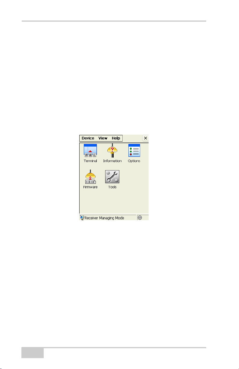
(Figure 1-1).
Main Window
The TRU main window consists of a menu bar, tool area, and a status
bar.
Figure 1-1. Main Window
The Menu Bar
The menu bar has the following components:
• Device – contains options which allow connecting to a device,
changing connection, hardware specific parameters, and the
application mode.
• View – shows or hides the status bar.
• Help – shows information on the current version and edition of
the Application.
1-2
Topcon Receiver Utility
Page 15
Application Modes
The Tool Bar
The tool area contains icons for the tools included in the current
mode. The tool area is inactive until a connection to a device is
established (the connection icon in the status bar is green).
The Status Bar
The status bar shows the current mode, and the connection status icon
(the green icon indicates that TRU is connected, the gray indicates
that there is no connection).
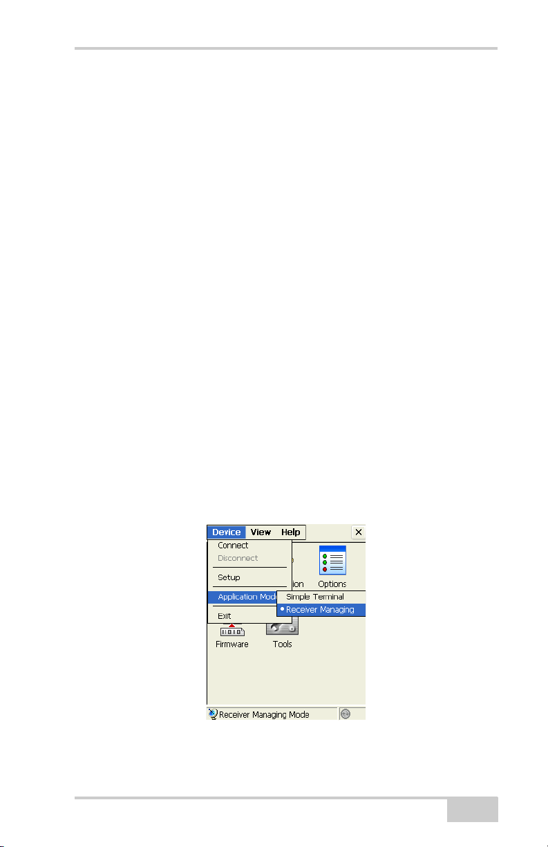
Application Modes
Topcon Receiver Utility has two main modes:
• Simple Terminal – In this mode, TRU is used only as a terminal.
This mode is also used for firmware updating of inoperative
receivers. For details on this mode, see “Simple Terminal” on
page 3-1.
• Receiver Managing (default) – In this mode, TRU is used for
configuring receiver hardware. For details on this mode, see
“Receiver Managing” on page 4-1.
You can choose the application mode from the Device menu:
Figure 1-2. Application Modes
P/N 7010-0908
1-3
Page 16

Getting Started
About Topcon Receiver Utility
Click on the Help menu to display the TRU dialog box. The TRU
dialog box displays the following fields:
• TRU Version – version number of software and date created.
• Edition – application edition.
• Copyright information – name of publishing company.
Figure 1-3. About Topcon Receiver Utility
Table 1-1 lists Application editions for Mobile devices currently
available.
Table 1-1. TRU Editions and Supported Platforms
# Edition CPU OS
1 Universal ARMV4 CE.NET
4.2-5.99
2 FC-100 ARMV4 CE.NET
4.2-5.99
3 FC-200 ARMV4I CE.NET
5.0-5.99
4 FC-2200 ARMV4I CE.NET
5.0-5.99
5 GMS-2 ARMV4I CE.NET
5.0-5.99
6 GMS-2 ARMV4I CE.NET
5.0-5.99
7 Universal ARMV4I Windows
Mobile
5.0-6.99
1-4
Top con
controllers
-AnyNo
FC-100/
2000
FC-110/
120/200
FC-2200 - AveLink
GMS-2 - GMS-2
GMS-2 Pro - Microsoft
FC-110/
120/200
3rd party
controllers
-No
- Microsoft
Any Microsoft
Topcon Receiver Utility
Bluetooth
Page 17

TIP
TIP
NOTICE
When installing the Application, the Mobile Installer will
automatically select the appropriate edition for the
controller.
NOTICE
It is guaranteed that the Application will work on any
Topcon controller listed in Table 1-1. We also support 3rd
party controllers, but there is no guarantee that the
Application will work on any 3rd party controller. Every
mobile device has its own and unique OS edition, and the
OS may not have components necessary for the
Application to function properly.
Setup
Setup
By default, the Application does not change the computer default
settings. To change defaults, you may select Device Setup from the
main menu. Select DeviceSetup from the main menu.
The Setup dialog box contains at least one General tab that allows
changing general-purpose parameters (Figure 1-4).
Figure 1-4. Setup/General-purpose Settings
P/N 7010-0908
1-5
Page 18

Getting Started
NOTICE
• Adjust serial port settings – when enabled, allows the Application
to change both controller’s and receiver’s serial port settings
(baud rate, flow control, etc.) to improve connection rate with the
receiver. Otherwise, the Application will detect and use current
settings of the receiver’s serial port.
NOTICE
This parameter effects operations in Receiver Managing
mode only.
On some platforms (GMS-2 and GMS-2 Pro) there is an additional
tab on the Setup dialog box with hardware-specific parameters
(Figure 1-5). The GMS tab controls power parameters of the internal
GPS receiver.
Figure 1-5. Setup / GMS-specific Settings
• Current power state – shows the current power state of the
internal GPS board of GMS-2/GMS-2 Pro, either ON or OFF.
• Power ON/OFF – turns on/off the GPS receiver power.
• Reset the receiver – performs a hardware reset of the internal
GPS receiver.
• Turn power ON when connecting to the internal receiver – check
mark this box for the Application to turn ON the internal GPS
board, when connecting to it.
1-6
Topcon Receiver Utility
Page 19

• Turn power OFF when connecting to the internal receiver –
check mark this box for the Application to turn OFF the internal
GPS board, when connecting to it.
• Turn power OFF on exit – check mark this box for the
Application to always turn OFF the internal GPS receiver power
on exit.
Setup
P/N 7010-0908
1-7
Page 20

Getting Started
Notes:
1-8
Topcon Receiver Utility
Page 21

Chapter 2
Connection
To establish a connection to the device, select DeviceConnect
from the main menu (Figure 2-1).
Figure 2-1. Connect Device
The Connection Parameters dialog box displays (see Figure 2-2 on
page 2-2).
P/N 7010-0908
2-1
Page 22

Connection
NOTICE
NOTICE
Connection Parameters
The Connection Parameters dialog box displays different
parameters, depending on the current application mode (Figure 2-2).
Figure 2-2. Connection Parameters for Simple Terminal and Receiver Managing
Modes
• Connect Using – select either Serial Port or Bluetooth device for
communication.
NOTICE
Bluetooth transport may not be available in the following
situations: the device-specific Bluetooth stack is not
supported by the Application, or the Bluetooth power is
turned off. If the Bluetooth power is off, please turn on the
Bluetooth power before using the Bluetooth manager.
NOTICE
If the Application edition for the specified platform doesn’t
support the installed Bluetooth stack, please use virtual
serial ports provided by Bluetooth manager for your
Bluetooth radio.
• Port name – shows physical and friendly name for the port. The
Application remembers the last used transport, and the last
2-2
Topcon Receiver Utility
Page 23

Connection Parameters
Context Menu
on Select a
Port Screen
successful port/device name for every transport, so it is easy to
connect to the same device.
If there is a friendly name for the port/device, you will see both
the friendly and physical name. Otherwise, only the physical
name is displayed. Press the list button to choose a port from the
Select a Port dialog (Figure 2-3).
• Connect – press to choose a port. The Select a Port dialog box
displays.
The Select a Port dialog box also displays both friendly and
physical names (if available).
Figure 2-3. Select a Port / Context Menu
On the Select a Port dialog box, click and hold on either a Friendly or
Port name to either select that port or get device information
(Figure 2-4 on page 2-4) on that port.
Use the context menu to refresh the contents of the Select a Port
dialog box, and open the Device Info dialog box to view information
about the selected serial port or Bluetooth device.
P/N 7010-0908
2-3
Page 24

Connection
Figure 2-4. Device Information
The Device Info dialog box shows both the physical and friendly
names of the serial port or Bluetooth device. The Class of Device for
Bluetooth devices also displays.
Detecting Hardware
Pressing the Connect button on the Connection Parameters dialog
box (see Figure 2-2 on page 2-2) establishes a connection to the
device you selected.
When the Application is in Simple Terminal mode, it just opens the
port. The Application won’t either try to detect the hardware
connected to the port, or change the port settings.
When the Application is in Receiver Managing mode, it will attempt
to detect the device connected to the port.
When detecting a receiver, the detecting a receiver dialog box
(Figure 2-5 on page 2-5) displays. An ActiveSync animated icon and
a Cancel button displays. Additional parameters display when using
serial transport, i.e., baud rate and flow control as shown in
Figure 2-5 on page 2-5
2-4
Topcon Receiver Utility
Page 25

Disconnecting Auto Detection
TIP
Figure 2-5. Detecting a Receiver
Press the Cancel button to terminate the process.
The Application always remembers the last successful port settings.
When you try to establish a new connection, the Application first tries
to use the last selected settings. The connection is established right
away if you are connecting to the same device.
Disconnecting Auto Detection
When in Receiver Managing mode the Application periodically
checks if the device is still connected by obtaining the receiver ID. If
connection to the device is lost, the following error message displays
(Figure 2-6).
Figure 2-6. Error Message – Connection to Receiver is Lost
The Application then closes the established connection and makes the
tool area inactive. The Application will not try to reconnect to the
device. You must choose an appropriate application mode and
transport, then initialize a new connection by selecting
DeviceConnect from the main menu.
TIP
Disconnection auto detection does not work when in
Simple Terminal mode or in Receiver Managing mode
while using the Terminal or Firmware Upload tools.
P/N 7010-0908
2-5
Page 26

Connection
NOTICE
NOTICE
When using a Bluetooth connection the OS can notify the
Application that the connection has physically been
broken (e.g., the remote device was switched off, or it was
moved too far from the controller). In that case, TRU also
closes the established connection irrespective of the
current application mode or active tool.
2-6
Topcon Receiver Utility
Page 27

Chapter 3
Simple Terminal
In Simple Terminal mode, Topcon Receiver Utility (TRU) does not:
• detect a device
• adjust port settings
• send any data to the port
This mode is intended for advanced users. Everything is decided by
the user in this pure manual mode.
Simple Manual mode can be used for the following:
• when you want to connect to a device that TRU doesn’t support.
• when you need to export firmware files to an inoperative receiver
that cannot even be detected (e.g., if the previous firmware
update has not been completed, and the receiver cannot be
detected in Receiver Managing mode).
If you choose Simple Terminal mode, you will see the following
icons on the desktop (Figure 3-1):
Figure 3-1. Simple Terminal – Main Window
P/N 7010-0908
3-1
Page 28

Simple Terminal
TIP
Table 3-1 describes the tool icons.
Table 3-1. Tool Icons
Button Description
Simple terminal icon
Firmware updating icon
TIP
To make the tool area active, first establish a port
connection on the controller using the Connect option from
the Device menu.
Terminal
Click the Te rm ina l icon to open the Term in al dialog box
(Figure 3-2).
Figure 3-2. Simple Terminal Screen
3-2
Topcon Receiver Utility
Page 29

Terminal
NOTICE
Menu Icon
Status
Bar
Main
View
Combo Box/
Drop-Down List
• The Terminal screen allows you to send commands through the
selected port using the edit area at the bottom of the dialog box,
and the Send button. The combo box remembers previous
commands, which can be selected from the drop-down list at the
bottom of the dialog.
• The status bar in the lower part of the dialog shows the current
state of transport for specific signals.
• The menu icon in the lower right corner of the Term in al dialog
box opens the pop-up menu of four options (Figure 3-3).
• Clear View – clears the main view.
• Send File – sends a file, that contains either commands or binary
data.
NOTICE
The Send File option sends files as is. The Application will
not change encoding or charset, add carriage returns, or
line feed characters.
• Escape Functions – opens the Escape dialog box to send
transport specific commands.
P/N 7010-0908
Figure 3-3. Terminal Pop-up Menu
3-3
Page 30

Simple Terminal
NOTICE
Figure 3-4. Escape Dialog Box – Send Transport Specific Commands
• Port Settings – opens the Port Settings dialog box to adjust port
settings (see Figure 3-5 on page 3-4).
Figure 3-5. Port Settings Dialog Box – (for serial transport)
NOTICE
When the Application is in Simple Terminal mode, it does
not change port settings.
3-4
Topcon Receiver Utility
Page 31

Firmware
NOTICE
NOTICE
Port settings depend on the OS. Usually the OS for the PC
remembers the previous port state, so if the port baud rate
was changed, the assigned value will be kept. CE.NET and
Windows Mobile will usually reset port settings by default.
I.e., the next time you open a serial port, you should adjust
port settings again.
Firmware
Click the Firmware icon to upload the firmware files to a nonfunctioning receiver. The Upload Firmware dialog box displays.
Figure 3-6. Upload Firmware
• Device – selects the device from the drop-down list, either
Receiver/Modem or Power Board.
• Firmware – press the folder icon to select the firmware files
that correspond to the device.
• Capture Method – only the Power On capture method is
available.
• Start – press to begin uploading firmware to the receiver in
Receiver Managing mode.
P/N 7010-0908
3-5
Page 32

Simple Terminal
NOTICE
NOTICE
Normally firmware updating is performed in Receiver
Managing mode. However, if a receiver becomes
inoperative, e.g., the previous receiver firmware updating
was not successful; only the Simple Terminal mode will be
available for use.
The firmware updating process in Simple Terminal mode is similar to
that discussed in Chapter 4, “Receiver Managing”. There is only one
exception; when it is in Simple Terminal mode, only the Power ON
capture method is available.
3-6
Topcon Receiver Utility
Page 33

Chapter 4
Receiver Managing
Receiver Managing mode is intended for configuring Topcon GNSS
receivers and firmware updating of GNSS receivers, internal
modems, power, and Bluetooth boards.
When in Receiver Managing mode, the Application tries to detect a
receiver at the time of connection. If there is no receiver, or if it
doesn’t respond, a connection cannot be established.
In Receiver Managing mode, you will see the following icons in the
tools area (Figure 4-1):
P/N 7010-0908
Figure 4-1. Receiver Managing – Main Window
4-1
Page 34

Receiver Managing
TIP
Table 4-1 describes the icons in Receiver Managing mode.
Table 4-1. Receiver Managing Tools Icons
Icon Description
Opens the Terminal. to adjust port settings.
View receiver information.
Current receiver options and allows uploading OAF files.
Updates firmware.
Opens a dialog that allows clearing NVRAM, or resetting the
receiver.
TIP
Initially, the Tools area is inactive. To make the tools area
active, first establish a port connection on the PC using the
Connect option from the Device menu (For details on
connection, see Chapter 2.)
4-2
Topcon Receiver Utility
Page 35

Terminal
NOTICE
Terminal
The same terminal dialog displays as that shown in Simple Terminal
mode (see Figure 3-2 on page 3-2).
There is only one difference between Simple Terminal and Receiver
Managing modes. While in Simple Terminal mode you have to
manually adjust port settings (for a serial cable connection). In
Receiver Managing mode the Application itself adjusts the port
settings automatically.
Information
Click on the Information icon to view receiver information. The
Receiver Info dialog box displays (Figure 4-2 on page 4-4) basic
information about the currently connected receiver (hardware and
firmware versions, RAM size, batteries condition, etc.):
• Name – shows the name of a parameter.
• Value – shows the current value of the parameter.
• Refresh – refreshes the parameter list.
• Save to File – saves the parameter names and their values to a
Unicode text file. By default the TRU sets the <receiver ID>.txt
file name.
NOTICE
Parameters not supported by the receiver are not shown.
P/N 7010-0908
4-3
Page 36

Receiver Managing
Figure 4-2. Receiver Information
Options
Click on the Options icon to manage receiver options. The Receiver
Options dialog box displays (Figure 4-3 on page 4-5) that allows you
to view the current authorization options and upload new ones.
The Receiver Options dialog box (Figure 4-3) has the following
parameters:
• Option Name – displays the current names for the receiver
options.
• Current – indicates whether the option is in force at the present or
not.
• Purchased – indicates whether the option is purchased or not.
• Leased – indicates whether the option is leased or not.
• Exp. Date – indicates the date the leased option will be disabled,
if applicable.
• Refresh – refreshes contents of the options.
• Upload OAF – uploads a new OAF file. By default, TRU offers
to use the <receiver ID>.tpo file name. The Upload OAF dialog
box displays (Figure 4-4 on page 4-5).
4-4
Topcon Receiver Utility
Page 37

Options
• Save to File – saves the dialog contents to a Unicode text file. By
default, TRU sets the <receiver ID>.opt.txt file name
(Figure 4-4).
Figure 4-3. Receiver Options
Upload OAF
After pressing the Upload OAF button from the Receiver Options
dialog box, you will be asked to enter the full path name of a file that
contains new authorization options for the receiver.
Then Upload OAF dialog displays information about the selected
OAF file (Figure 4-4). You can select another OAF if needed.
Figure 4-4. Upload OAF
P/N 7010-0908
4-5
Page 38

Receiver Managing
Topcon Receiver Utility (TRU) initially checks to see if the file you
selected is compatible with the currently connected receiver.
If you chose a file not intended for this receiver, TRU displays an
error icon next to the Receiver ID and disables the Upload OAF
button (Figure 4-5).
Figure 4-5. Selecting Wrong OAF
1. After you press the Upload OAF button, the contents of the
dialog box will change. It will show the options that have been
installed with the new OAF, and the progress bar (Figure 4-6).
Figure 4-6. Options Uploading in Progress
If you are updating authorization options for a TruPath receiver, or
another receiver model that supports the new Digest cipher, neither
option names, nor the result will be displayed. When the OAF file is
4-6
Topcon Receiver Utility
Page 39

Firmware
NOTICE
NOTICE
uploaded to the receiver, the TRU will display a message box
informing you about the results (Figure 4-7).
Figure 4-7. Reset the Receiver
If an OAF file is uploaded to the receiver, the Application will offer
to reset the receiver to put new authorization options into operation
(Figure 4-7).
Firmware
To upload firmware files to Topcon receivers, press the Firmware
icon. The Upload Firmware dialog box displays (Figure 4-8 on
page 4-8). This dialog allows you to upload firmware files to the
receiver that is connected to the computer and has the following
parameters:
NOTICE
NOTICE
P/N 7010-0908
Don’t use a Bluetooth connection (either native Bluetooth
connection, or via a virtual serial port) when updating
firmware. The Firmware updating procedure resets the
receiver to switch it into firmware updating mode.
Resetting the Receiver may break the Bluetooth
connection and this in turn may interrupt the firmware
uploading process.
Be extremely attentive when selecting firmware updating
parameters, especially when updating modem firmware.
Some modem models don’t allow terminating of the
firmware updating process. So if you choose incorrect
4-7
Page 40

Receiver Managing
TIP
parameter combinations, or interrupt the firmware
updating process, it may damage your equipment. If this
happens, and you cannot update firmware using even the
Power On capture, you will need to have the hardware
serviced.
Figure 4-8. Upload Firmware
• Device – select either Receiver/Modem or Power B o a rd from the
Device drop-down list.
TIP
If you are updating firmware for a power board, you must
select Power Board from the combo box. Otherwise (if you
are updating GPS, modem, or Bluetooth firmware), you
must select the Receiver/Modem option.
• Firmware – specify the full path to firmware files corresponding
to the device by pressing the folder icon or enter the full path
manually.
4-8
Topcon Receiver Utility
Page 41

TIP
TIP
NOTICE
NOTICE
If you are updating power board firmware, you should
specify only the path to the RAM file (it usually has an .ldr
extension). Otherwise, you should specify full paths to both
RAM and Flash files (the flash file usually has an .ldp
extension).
NOTICE
Attention GMS-2, and GMS-2 Pro users. Firmware for the
GMS receiver board consists of one RAM file and two
Flash files (usually Master.ldp, and Slave.ldp). You have to
update receiver firmware in two iterations. The first time
you should select the RAM file and the first Flash file. Once
firmware is successfully uploaded, you should select the
same RAM file, and the other Flash file, and repeat
firmware upgrading.
Firmware
•Capture Method – select either the Soft Break, or the Powe r O N
capture method. If you select the Soft Break method, the receiver
will be switched into firmware updating mode through the
software. If you select the Power ON capture method, after you
press the Start button, you will need to press the reset button on
the receiver, or turn it off, then on again.
NOTICE
Attention GMS-2, and GMS-2 Pro users. If you are
updating firmware using the Power ON capture method
when connecting to the internal GMS receiver, you will not
have to reset the receiver. The Application does it
automatically.
• Start – press to begin uploading firmware to the receiver in
Receiver Managing mode. After you press the button, it toggles
to Cancel. Pressing this button terminates the firmware updating
process.
P/N 7010-0908
4-9
Page 42

Receiver Managing
NOTICE
NOTICE
If the firmware updating process for a device has not been
completed, the device may become inoperative.
After the firmware updating process has been successful (uploaded),
the following message displays (Figure 4-9):
Figure 4-9. Successful Updating Firmware
Otherwise, one of the following error messages found in Table 4-2
will display.
To detect and fix the problem, please use troubleshooting procedures
described in Table 4-2 below.
Table 4-2. Firmware Updating Error Messages, and Troubleshooting
Error Message Troubleshooting
Unknown error Repeat firmware updating. If the error
repeats, please contact your dealer or
manufacturer. It usually means that
there is a hardware problem, or your
Flash file was corrupted.
The RAM file is not compatible with
the hardware
The Flash file is not compatible with
the hardware
The specified device requires a newer
version of the loader
The RAM (.ldr) file you selected is not
compatible with your hardware. Please
select appropriate .ldr file and repeat
firmware updating.
The Flash (.ldp) file you selected is not
compatible with your hardware. Please
select the appropriate .ldp file and
repeat firmware updating.
The version of the Application you are
using cannot upload firmware to your
device. You need to receive a more
recent Application version from your
dealer.
4-10
Topcon Receiver Utility
Page 43

Tools
Table 4-2. Firmware Updating Error Messages, and Troubleshooting
Error Message Troubleshooting
The RAM file, checksum is incorrect Repeat firmware updating. If the error
repeats, it means that the RAM file you
have was corrupted, and it needs to be
replaced with correct RAM file.
No response from the device Usually this means that the device was
disconnected from the controller. Make
sure that a cable is reliably attached to
both the device, and the controller, and
repeat firmware updating.
Tools
The Tools icon opens the Send Command dialog box that allows you
to reset the receiver and to clear the NVRAM.
Figure 4-10. Send Command
• Reset Receiver – leaves all files intact. Resetting the receiver is
similar to a hot resetting of the computer, but without going
through a power cycle.
After a receiver reset operation, the receiver requires a few
seconds to a few minutes to begin tracking satellites and logging
data.
P/N 7010-0908
4-11
Page 44

Receiver Managing
• Clear NVRAM – this command will not delete any files from the
receiver memory. It will reset the receiver parameters to factory
default values (such as active antenna input, elevation mask and
recording interval, and information about the receiver’s internal
file system).
After clearing the NVRAM, the receiver will require some time
to collect new ephemerides and almanacs (around 15 minutes).
Clearing the NVRAM can be interpreted as a “cold reset” of your
computer.
4-12
Topcon Receiver Utility
Page 45

Notes:
Notes
Page 46

Notes:
Notes
Page 47

Page 48

Topcon Positioning Systems, Inc.
7400 National Drive, Livermore, CA 94550
800∙443∙4567 www.topconpositioning.com
ISO 9001:2000
FM 68448
Topcon Receiver Utility Reference Manual
P/N: 7010-0908 Rev A 08/08
©2008 Topcon Corporation All rights reserved. No unauthorized duplication.
 Loading...