

USER MANUAL
COMPU-VISION
CV-5000
CV-5000


INTRODUCTION
Thank you for purchasing the TOPCON Compu-Vision CV-5000.
INTENDED USE / INDICATIONS FOR USE
This instrument is used to measure the refractive power of the eye and to test binocular
functionality.
FEATURES
This instrument has the following features:
The compact design enables you to see the patient's face.
The distance acuity chart can be controlled by a personal computer.
The PD (pupli distance) and the anterior eye alignment can be checked even in a dark
optometry room.
"Help", "Mouse Navigation" and other functions support the optometrist.
PURPOSE OF THIS MANUAL
To ensure safe and effective use of the instrument, carefully read "DISPLAY FOR SAFE USE"
and "SAFETY CAUTIONS" and then use the instrument as instructed.
Keep the user manual at hand for future reference.
INTENDED PATIENT POPULATION
The patient who undergoes an examination by this instrument must maintain concentra-
tion for a few minutes and keep to the following instructions:
To fix the face to the forehead rest.
To understand and follow instructions when undergoing an examination.
CAUTION : Federal laws restricts this device to the sale by or on the order of a physician.
1. No part of this manual may be copied or reprinted, in whole or in part, without prior written
permission.
2. The contents of this manual are subject to change without prior notice and without legal
obligation.
3. The contents of this manual are correct to the best of our knowledge. Please inform us of
any ambiguous or erroneous descriptions, missing information, etc.
4. Original Instructions
This instruction manual was originally written in English.
1

DISPOSAL
This symbol is applicable for EU member countries only.
To avoid potential negative consequences for the environment and possibly human
health, this instrument should be disposed of (i) for EU member countries - in
accordance with WEEE (Directive on Waste Electrical and Electronic Equipment),
or (ii) for all other countries, in accordance with local disposal and recycling laws.
Dispose of the instrument according to local disposal and recycling laws.
ENVIRONMENTAL CONDITIONS FOR USE
Temperature : 10°C - 40°C
Humidity : 30% - 90% (non-condensing)
Air pressure : 700hPa - 1060hPa
STORAGE, USAGE PERIOD
1. Storage (without wrapping (without package))
* Temperature: 10°C - 40°C
Humidity: 10% - 95% (without dew condensation)
Air pressure: 700hPa - 1060hPa
* THIS INSTRUMENT DOES NOT MEET THE TEMPERATURE REQUIREMENTS OF
ISO 15004-1 FOR STORAGE. DO NOT STORE THIS INSTRUMENT IN CONDITIONS
WHERE THE TEMPERATURE MAY RISE ABOVE 40°C OR FALL BELOW 10°C.
2. Storage (with wrapping (with package))
Temperature: -20°C - 50°C
Humidity: 10% - 95%
3. Transportation (with wrapping (with package))
Temperature: -40°C - 70°C
Humidity: 10% - 95%
4. When storing the instrument, ensure that the following conditions are met:
(1) The instrument should not be splashed with water.
(2) Store the instrument away from the environment where air pressure, temperature,
humidity, ventilation, sunlight, dust, salty/sulfurous air, etc. could cause damage.
(3) Do not store or transport the instrument on a slope or uneven surface or in an area
where it is subject to vibrations or instability.
(4) Do not store the instrument where chemicals are stored or gas is generated.
5. Usage period
8 years from delivery providing regular maintenance is performed (according to the self-certification [Topcon data])
CHECKPOINTS FOR MAINTENANCE
Maintenance by user
1. Before use, ensure that the measuring head is installed securely.
2. Regularly maintain and check the instrument and its parts.
3. When using the instrument after a prolonged period of inactivity, confirm normal and safe
operation beforehand.
4. When the lens is soiled, wipe it with the accessory silicone cloth.
5. When this instrument is not in use, apply the dust cover to it.
6. Refer to "7. MAINTENANCE" on P.156 for details.
2

HOW TO READ THIS USER MANUAL
• Before using the CV-5000 instrument, read the cautions described on P.1 to P.8.
• For connecting to other devices, read "6.1.1 CONNECTING PERIPHERAL DEVICES" on P.120.
• For quick start up, refer to "3. BASIC OPERATIONS" on P.54 first.
• For setup, refer to "6. CONVENIENCE FUNCTIONS" on P.119.
• The following symbols are used in this manual. Please understand these symbols and their
meaning and use the instrument correctly.
: Describes the convenience functions and the cautions to ensure safe use.
: Describes the location of supplemental or additional information.
• The following abbreviations indicate the devices relevant to the instrument.
Abbreviation Device
RM Auto refractometer
KR Auto kerato-refractometer
CL Computerized lensmeter
EZ EZ meter
ACP Auto chart projector
MC Mirror chart
PC Pixel chart
3
DISPLAY FOR SAFE USE
To encourage safe and proper use and to prevent danger to the operator and others or potential
damage to property, important cautionary messages are placed on the instrument body and
inserted in the user manual.
We suggest that everyone using the instrument understand the meaning of the following displays,
icons and text before reading the "SAFETY CAUTIONS" and observe all listed instructions.
DISPLAYS
Display Meaning
ICONS
WARNING
CAUTION
Injury refers to cuts, bruises, burns, electric shock, etc. which do not require hospital-
ization or extended medical treatment.
Physical damage refers to extensive damage to the building, nearby equipment and/
or surrounding furniture.
Icon Meaning
Incorrect handling by ignoring this display may lead to a risk of
death or serious injury.
Incorrect handling by ignoring this display may lead to personal
injury or physical damage.
Prohibition:
Specific content is expressed with words or a picture near the
icon.
Mandatory Action:
Specific content is expressed with words or a picture near the
icon.
Caution:
Specific content is expressed with words or a picture near the
icon.
4
GENERAL SAFETY INFORMATION
WARNING
Ensuring the Safety of Patients and Operators
Be careful not to bump the patient's eyes or nose with the instrument during operation.
The patient may be injured.
Preventing Electric Shocks and Fires.
To avoid fire and electric shock, install the instrument in a place free of water and other liquids.
To avoid fire and electric shock, do not put cups or other containers with liquids near the instrument.
To avoid electric shock, do not insert metal objects into any openings, etc.
To avoid fire in the event of an instrument malfunction, immediately turn off the power switch
and unplug the cable if you see smoke coming from the instrument or if you detect other problems. Don't install the instrument where it is difficult to disconnect the power plug from the
outlet. Ask your dealer for repairs.
5
CAUTIONS
Ensuring the Safety of Patients and Operators
This instrument should only be used by skilled operators.
When moving the measuring head up and down, be careful not to bump it against the patient's
face.
The patient may be injured.
To prevent the instrument from tipping over or falling and to avoid injury, do not install the
instrument on an uneven, unsteady or sloping surface.
Preventing Electric Shocks and Fires.
To avoid damage to the instrument or an injury caused by electric shock, turn off the power
switch and unplug the power cord before cleaning the instrument.
Electromagnetic Compatibility (EMC)
This instrument has been tested (with 100V/120V/230V) and found to comply with IEC606011-2 Ed.3.0: 2007.
This instrument radiates radio frequency energy within standard and may affect other devices
in the vicinity.
If you have discovered that turning on/off the instrument affects other devices, we recommend
you change its position, keep a proper distance from other devices, or plug it into a different
outlet.
Please consult the dealer from whom you purchased the instrument if you have any additional
questions.
6
MAINTENANCE
To ensure the safety and performance of this instrument, all maintenance work, unless specified in
this manual, shall be conducted by trained service engineers.
The following maintenance tasks may be performed by the user.
For details, see the relevant parts of this manual as specified below.
Replacing the face shield/forehead rest
The forehead rest and face shield on this instrument may be replaced by the user.
: Refer to " INSTALLING AND REMOVING THE FACE SHIELD AND FOREHEAD
REST" on P.38 for handling instructions.
Replacing the fuse
The fuses on this instrument may be replaced by the user.
: For details, refer to " REPLACING THE FUSE" on P.157.
Inspecting the instrument
It is recommended to inspect the mounting section of the CV-5000 and the system table periodically to ensure they are attached properly.
: Refer to " INSPECTING THE MEASURING HEAD MOUNTING SECTION" on P.159.
ESCAPE CLAUSE
TOPCON shall not take any responsibility for damage due to fire, earthquakes, actions
by third persons and other accidents, or damage due to negligence and misuse by the
user and any use under unusual conditions.
TOPCON shall not take any responsibility for damage derived from inability to properly
use this instrument, such as loss of business profit and suspension of business.
TOPCON shall not take any responsibility for damage caused from using this instru-
ment in a manner other than that described in this user manual.
Diagnoses made shall be the responsibility of the user and TOPCON shall not take
any responsibility for the results of such diagnoses.
7
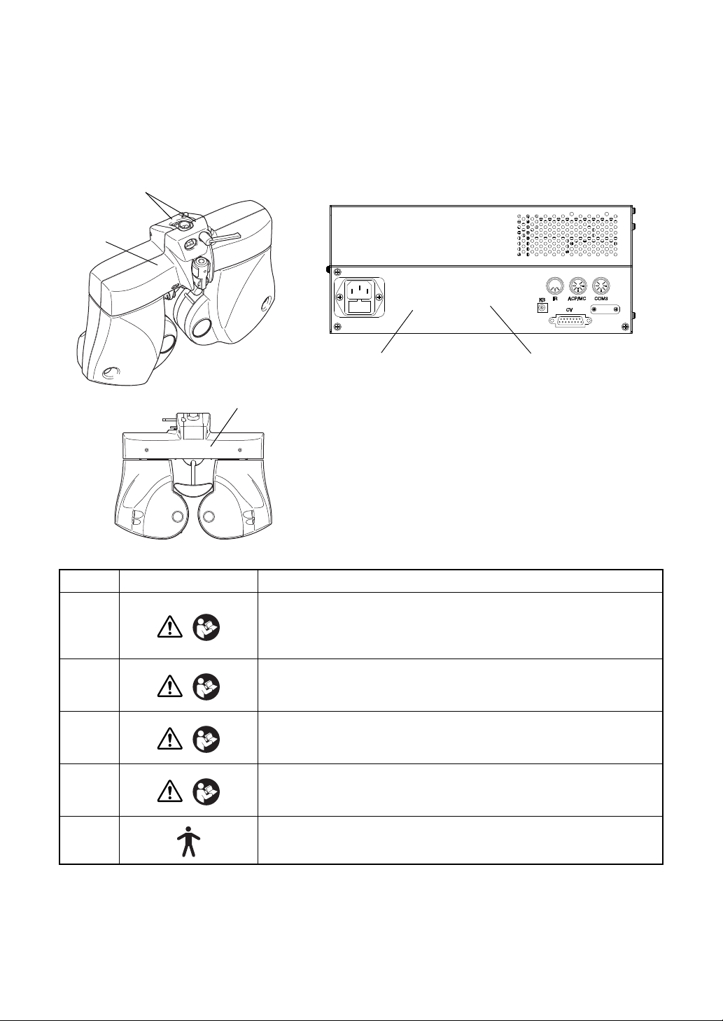
WARNING DISPLAYS AND POSITIONS
3
4
12
5
To ensure safety, the machine provides warning displays.
Use the instrument correctly by observing the display instructions. If any of the following display
labels are missing, contact your TOPCON dealer or your local Topcon office listed on the back
cover of this manual.
No. Label Meaning
WARNING
1
2
3
4
5
Electoric shock may cause bums or a possible fire. Turn the power
switch OFF and unplug the power cord before replacing the fuses.
Replace only with fuses of the correct rating.
WARNING
To avoid injury caused by electric shock, do not open the cover.
Ask your dealer for service.
CAUTION
Do not put your hand between the mounting arm and the instrument. Your hand may be pinched.
CAUTION
To avoid injury due to contact, do not bring the patient’s face close
to the near-point rod.
Degree of protection against electric shock
: TYPE B APPLIED PART
8

CONTENTS
INTRODUCTION ...............................................................................................................1
HOW TO READ THIS USER MANUAL ............................................................................ 3
DISPLAY FOR SAFE USE ............................................................................................... 4
GENERAL SAFETY INFORMATION ................................................................................ 5
MAINTENANCE ................................................................................................................ 7
ESCAPE CLAUSE ............................................................................................................ 7
WARNING DISPLAYS AND POSITIONS ......................................................................... 8
1.BEFORE USE
1.1 CHECKING THE ACCESSORIES .................................................................................. 15
OPTIONAL ACCESSORIES ...................................................................................... 16
PRODUCTS SOLD SEPARATELY ........................................................................... 17
1.2 COMPONENT NAMES AND FUNCTIONS .................................................................... 18
1.2.1 MAIN UNIT(Measuring head) .................................................................................18
COMPOSITION OF PARTS WHICH CONTACT THE HUMAN BODY ..................... 19
1.2.2 CV POWER SUPPLY UNIT WITH EXTERNAL PERSONAL COMPUTER
(POWER SUPPLY UNIT) ................................................................................................ 20
1.2.3 TEST SCREEN ......................................................................................................22
MENU BAR/TOOLBAR ............................................................................................ 23
DATA DISPLAY UNIT ..............................................................................................32
VISUAL ACUITY CHART OPERATION UNIT .........................................................36
FUNCTION BUTTON ..............................................................................................36
CONTROL WINDOW ..............................................................................................37
2.INSTALLATION
2.1 INSTALLING THE MEASURING HEAD .........................................................................38
LEVEL ADJUSTMENT ............................................................................................... 38
INSTALLING AND REMOVING THE FACE SHIELD AND FOREHEAD REST ........ 38
ASSEMBLY/INSTALLATION OF NEAR-POINT ROD AND NEAR-POINT CARD .... 39
2.2 CONNECTING THE MEASURING HEAD, PERSONAL COMPUTER ........................... 40
2.3 CONNECTING THE VISUAL ACUITY CHART .............................................................. 41
CONNECTING A DEVICE TO RS-232C (ACP-8, MC-3.) ......................................... 41
CONNECTING A DEVICE TO INFRARED COMMUNICATION
(ACP-8, MC-3.) ............................................................................................................... 41
CONNECTING A DVI DEVICE (PC-50S, PC-50SB, MC-4S) .................................... 41
2.4 INSTALLATION OF CV-5000 SOFTWARE ....................................................................42
9

2.5 SETTINGS OF DISPLAY PROPERTIES (ONLY WHEN A DVI DEVICE IS
USED AS A VISUAL ACUITY CHART) ................................................................................48
2.6 INITIAL SETTINGS (REGISTERING THE VISUAL ACUITY CHART OR OTHERS) .....51
3.BASIC OPERATIONS
3.1 FLOW OF OPERATIONS ...............................................................................................54
3.2 PREPARATION BEFORE MEASUREMENT ..................................................................54
3.2.1 PREPARATION FOR TEST ...................................................................................54
3.2.2 DATA INPUT ...........................................................................................................56
3.3 TEST ...............................................................................................................................59
SELECT THE TEST CHART AND EXECUTE THE TEST. ....................................... 59
SELECT THE PROGRAM COURSE AND EXECUTE THE TEST. ........................... 59
SELECT THE TEST NAME AND EXECUTE THE TEST. ......................................... 60
3.4 PRESCRIPTION .............................................................................................................61
3.5 OUTPUTTING THE RESULT .........................................................................................61
3.6 RESETTING ....................................................................................................................61
4.GENERAL OPTOMETRY PROCEDURE
4.1 DATA INPUT ...................................................................................................................62
4.2 FAR-POINT REFRACTIVE POWER MEASUREMENT .................................................62
REFRACTIVE POWER MEASUREMENT BY USING CROSS CYLINDER ............. 62
REFRACTIVE POWER MEASUREMENT USING ASTIGMATISM TEST CHART ... 63
4.3 NEAR-POINT REFRACTIVE POWER MEASUREMENT ............................................... 63
4.4 BINOCULAR MEASUREMENT ......................................................................................64
FAR-POINT PHORIA ................................................................................................. 64
NEAR-POINT PHORIA .............................................................................................. 64
5.OPERATION FOR TESTS
5.1 VISUAL ACUITY TEST/SPHERICAL POWER/CYLINDER POWER CORRECTION ....65
5.1.1 VISUAL ACUITY MEASUREMENT ........................................................................65
5.1.2 R/G TEST ...............................................................................................................66
5.1.3 ASTIGMATISM TEST ............................................................................................. 68
5.1.4 CROSS CYLINDER TEST (JACKSON CROSS) .................................................... 69
5.1.5 CROSS CYLINDER TEST (TOPCON CROSS) .....................................................71
5.1.6 SMART CROSS TEST ...........................................................................................73
5.1.7 BALANCE TEST (POLARIZATION) ....................................................................... 75
5.1.8 BALANCE TEST (POLARIZATION: 2-COLOR) ..................................................... 76
5.1.9 BALANCE TEST (PRISM) ......................................................................................78
10

5.2 PHORIA TEST ................................................................................................................80
5.2.1 PHORIA TEST (POL. CROSS) ...............................................................................80
5.2.2 PHORIA TEST (CROSS RING) .............................................................................. 82
5.2.3 PHORIA TEST (MADDOX) ..................................................................................... 83
5.2.4 HORIZONTAL PHORIA MEASUREMENT (PRISM SEPARATION) ......................86
5.2.5 VERTICAL PHORIA MEASUREMENT (PRISM SEPARATION) ............................88
5.3 OTHER BINOCULAR FUNCTION TESTS ..................................................................... 90
5.3.1 FIXATION DISPARITY TEST (POL. CROSS WITH FIXATION TARGET) ............90
5.3.2 CONVERGENCE/DIVERGENCE ........................................................................... 92
5.3.3 Vertical vergence ....................................................................................................95
5.3.4 STEREO TEST ....................................................................................................... 97
5.3.5 COINCIDENCE TEST (H) (Only for ACP-8) ...........................................................99
5.3.6 COINCIDENCE TEST (V) ..................................................................................... 101
5.3.7 WORTH 4 DOTS TEST ........................................................................................103
5.3.8 SHEARD'S CRITERIA ..........................................................................................105
5.4 NEAR-POINT TEST ......................................................................................................107
5.4.1 ADD TEST ............................................................................................................107
5.4.2 MONOCULAR ADD TEST ....................................................................................108
5.4.3 MINUS LENS AMPLITUDE MEASUREMENT ..................................................... 110
5.4.4 POSITIVE RELATIVE ACCOMMODATION MEASUREMENT ............................112
5.4.5 NEGATIVE RELATIVE ACCOMMODATION MEASUREMENT ...........................114
5.4.6 AC/A ......................................................................................................................116
6.CONVENIENCE FUNCTIONS
6.1 USING THE DATA OF PERIPHERAL DEVICES .........................................................119
6.1.1 CONNECTING PERIPHERAL DEVICES .............................................................120
6.1.2 SETTING FOR CONNECTION .............................................................................121
SETTING FOR SERIAL CONNECTION .................................................................. 121
6.1.3 IMPORTING THE DATA FROM OTHER DEVICES .............................................123
SETTING THE DATA CAPTURING METHOD ........................................................ 123
DISPLAY RM/CL DATA LIST .................................................................................. 124
LOAD LAST DATA FROM RM/CL ........................................................................... 126
LOAD LAST DATA FROM SELECTED SOURCE ................................................... 126
When you select [RM] ............................................................................................126
When you select [CL] .............................................................................................126
When you select [RM+CL] .....................................................................................126
IMPORT DATA FILE ................................................................................................ 126
6.1.4 INPUTTING OTHER DATA EXCEPT "SUBJECTIVE" MANUALLY .....................127
6.2 TESTS ...........................................................................................................................128
6.2.1 CHECKING THE TEST METHOD ........................................................................ 128
11

HELP/MINI HELP UTILITY ...................................................................................... 128
MOUSE NAVIGATION UTILITY .............................................................................. 129
6.2.2 CONVENIENCE FUNCTIONS DURING TEST ....................................................129
SELECTING THE CHANGING STEP FOR LENS ................................................... 129
CHANGING THE AUXILIARY LENS ....................................................................... 130
SELECTING THE TYPE OF OCCLUSION .............................................................. 131
SETTING THE VISUAL ACUITY VALUE DIRECTLY .............................................. 132
SETTING THE CYLINDER AXIS DIRECTLY .......................................................... 133
CANCELLING THE PRISM TEMPORARILY ........................................................... 133
SELECTING THE POLARIZATION LENS ............................................................... 134
DISPLAYING/HIDING THE REFERENCE DATA .................................................... 134
CHANGING THE REFERENCE DATA .................................................................... 135
CHANGING THE MAIN DATA ................................................................................. 135
CHANGING THE MAIN DATA AND REFERENCE DATA TO EACH OTHER ........ 136
TRANSPOSING THE SYMBOL OF CYLINDER POWER
(POWER CONVERSION) ............................................................................................. 136
RECORDING AND DISPLAYING THE PRESCRIPTION DATA ............................. 137
CANCELING THE NEAR-POINT CORRECTION TEMPORARILY ......................... 137
6.2.3 OPERATING THE VISUAL ACUITY CHART .......................................................138
APPLYING THE MASK TO THE TEST CHART ...................................................... 138
SETTING THE R/G FILTER TO THE TEST CHART ............................................... 138
CHANGING THE TEST CHART WITHOUT CHANGING THE TEST ..................... 138
ADJUSTMENT OF NEAR-POINT CARD ................................................................ 139
Target name on the patient side ............................................................................139
6.2.4 TILTING DOWNWARD .........................................................................................140
6.3 REGISTRATION ........................................................................................................... 141
6.3.1 CUSTOMIZING THE CHART PAGE .................................................................... 141
CHANGING THE TEST CHART LAYOUT ON THE CHART PAGE ....................... 141
CHANGING THE TEST RELATED TO THE TEST CHART .................................... 142
CHANGING THE TEST CHART USED IN CROSS CYLINDER TEST ................... 145
6.3.2 CUSTOMIZE THE TEST PROCEDURE .............................................................. 146
6.4 EXPLANATION .............................................................................................................150
6.4.1 DATA TO BE PRINTED ........................................................................................ 150
6.4.2 USING THE PATIENT EDUCATION TOOLS FOR THE PATIENT ......................151
OPERATIONS ENABLED BY THE EXPLANATION TOOLS .................................. 151
Human eye ............................................................................................................151
Progressives .......................................................................................................... 154
Accommodation .....................................................................................................154
Eye Message .........................................................................................................155
12

7.MAINTENANCE
DAILY CHECKUPS .................................................................................................. 156
ORDERING CONSUMABLES ................................................................................. 156
USER MAINTENANCE ITEMS ................................................................................ 156
REPLACING THE FUSE ......................................................................................... 157
CLEANING ............................................................................................................... 158
Cleaning parts which contact the patient ...............................................................158
Cleaning the lens ................................................................................................... 158
INSPECTING THE MEASURING HEAD MOUNTING SECTION ........................... 159
Point for inspection ................................................................................................159
8.SETTING
8.1 BASIC OPERATION FOR "SETTINGS" MENU ...........................................................160
8.2 "SETTINGS" MENU LIST .............................................................................................163
8.2.1 General settings .................................................................................................... 167
8.2.2 Function settings ...................................................................................................169
8.2.3 Examination settings ............................................................................................. 172
8.2.4 Chart settings ........................................................................................................176
Chart page registration ............................................................................................ 178
Cross cylinder chart reg. .......................................................................................... 181
8.2.5 Course registrations ..............................................................................................182
8.2.6 Data I/O settings ................................................................................................... 185
System configurations .............................................................................................. 187
8.2.7 Screen settings ..................................................................................................... 192
CUSTOMIZE TOOLBAR .......................................................................................... 194
8.2.8 Update ..................................................................................................................196
8.3 SETTING ON Windows .................................................................................................198
8.3.1 SETTING WHEN USING THE PRINT FUNCTION .............................................. 198
Setting of IE (Internet Explorer) .............................................................................198
8.3.2 WHEN USING THE PRE-INSTALLED SHARED FOLDER .................................. 198
9.APPENDICES
9.1 LIST OF AUXILIARY LENS AND MOUSE NAVIGATION ............................................199
AUXILIARY LENS .................................................................................................... 199
MOUSE NAVIGATION ............................................................................................. 201
9.2 SHAPE OF PLUG .........................................................................................................203
SYMBOL .................................................................................................................. 203
9.3 CORNEAL ALIGNING DEVICE ....................................................................................204
Conversion value (When the measured refractive power is plus notation) ............205
13

Conversion value (When the measured refractive power is minus notation) .........205
10.TROUBLE SHOOTING
TROUBLE SHOOTING GUIDE ............................................................................... 206
11.SPECIFICATIONS AND PERFORMANCE
DIMENSIONS AND WEIGHT .................................................................................. 218
PURPOSE OF USE ................................................................................................. 219
OPERATING PRINCIPLE ........................................................................................ 219
PATIENT’S ENVIRONMENT ................................................................................... 220
ELECTRIC RATING ................................................................................................. 220
ELECTROMAGNETIC COMPATIBILITY ................................................................. 221
REQUIREMENT TO THE EXTERNAL CONNECTION DEVICES .......................... 224
SYSTEM CLASSIFICATION .................................................................................... 225
Index ...................................................................................................................................226
14
1. BEFORE USE
1.1 CHECKING THE ACCESSORIES
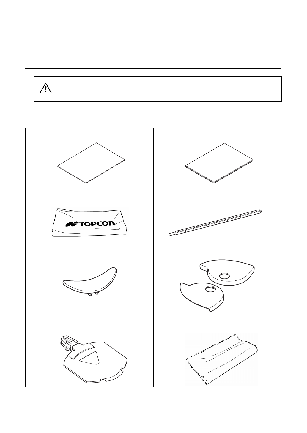
CAUTION
Upon unpacking, make sure that all the following standard accessories are included. Figures
in ( ) are the quantities.
Instruction manual User manual (1)
Dust cover (1) Near-point rod (1)
Forehead rest (1) Face shield (2)
Install the devices (RM, CL and others), which will be connected with
the optional accessories, out of the CV-5000 patient's environment.
INSTRUCTION MANUAL
USER MANUAL
Near-point card and card holder (1 each) Silicone cloth (1)
15
1. BEFORE USE

Fuses (2) Power cord (1)
The shape is different according to the destination.
Measuring head connection cable (1) Install CD (1)
Use the standard accessories except the following units in the patient's environment.
• User manual
• Dust cover
• Silicone cloth
OPTIONAL ACCESSORIES
The optional accessories must be connected by a service engineer. If you have purchased any optional accessories, contact a service engineer.
• Communication cable (DIN/DIN)
This cable is used to connect the visual acuity chart.
Both ends of the cable are the DIN connector type.
• Communication cable (DIN/D-sub)
This cable is used to connect the power supply unit, KR, CL and others to a personal computer. One end of the cable is the DIN connector type and the other is the D-SUB 9-pin type.
• Infrared communication unit
This unit is used to perform infrared communication with the visual acuity chart.
• Pixel Chart (PC-50S)
This visual acuity chart operates in linkage with the CV system.
• Pixel Chart (PC-50SB)
This visual acuity chart operates in linkage with the CV system.
• Mirror Chart (MC-4S)
This visual acuity chart operates in linkage with the CV system.
16
1. BEFORE USE

PRODUCTS SOLD SEPARATELY
The commercial products sold separately are necessary to use the CV system. Use the
device complying with UL60950/UL60950-1 or IEC60950/IEC60950-1.
• Personal computer (including the main unit, display, keyboard and mouse)
Your personal computer must meet the following specifications.
OS: Windows XP Professional (32 bits)/Windows 7 Professional (32 bits/64 bits)
CPU: Clock frequency is 1GHz or more.
Memory: 1GB or more (32-bit OS)/2GB or more (64-bit OS)
HDD: Free capacity of 500MB or more
Serial port: 1 or more
Display: Resolution of SXGA (1280 x 1024) or more
At least one serial port is necessary to connect to the power supply unit.
To connect to RM/CL, more serial ports for the connected devices are necessary.
To connect Pixel Chart or Mirror Chart (optional) as a visual acuity chart, a free DVI
connector is necessary.
To connect another CV-5000 system, the LAN connecter is needed.
17
1. BEFORE USE
1.2 COMPONENT NAMES AND FUNCTIONS
(4)
(13)
(9)
(6)
(5)
(3)
(1)
(12)
(2)
(15)
(10)
(8)
(11)
(7)
(14)
CAUTION
Use all the components in the patient's environment.
To avoid electric shock, do not touch the external connection terminal
and the patient at the same time.
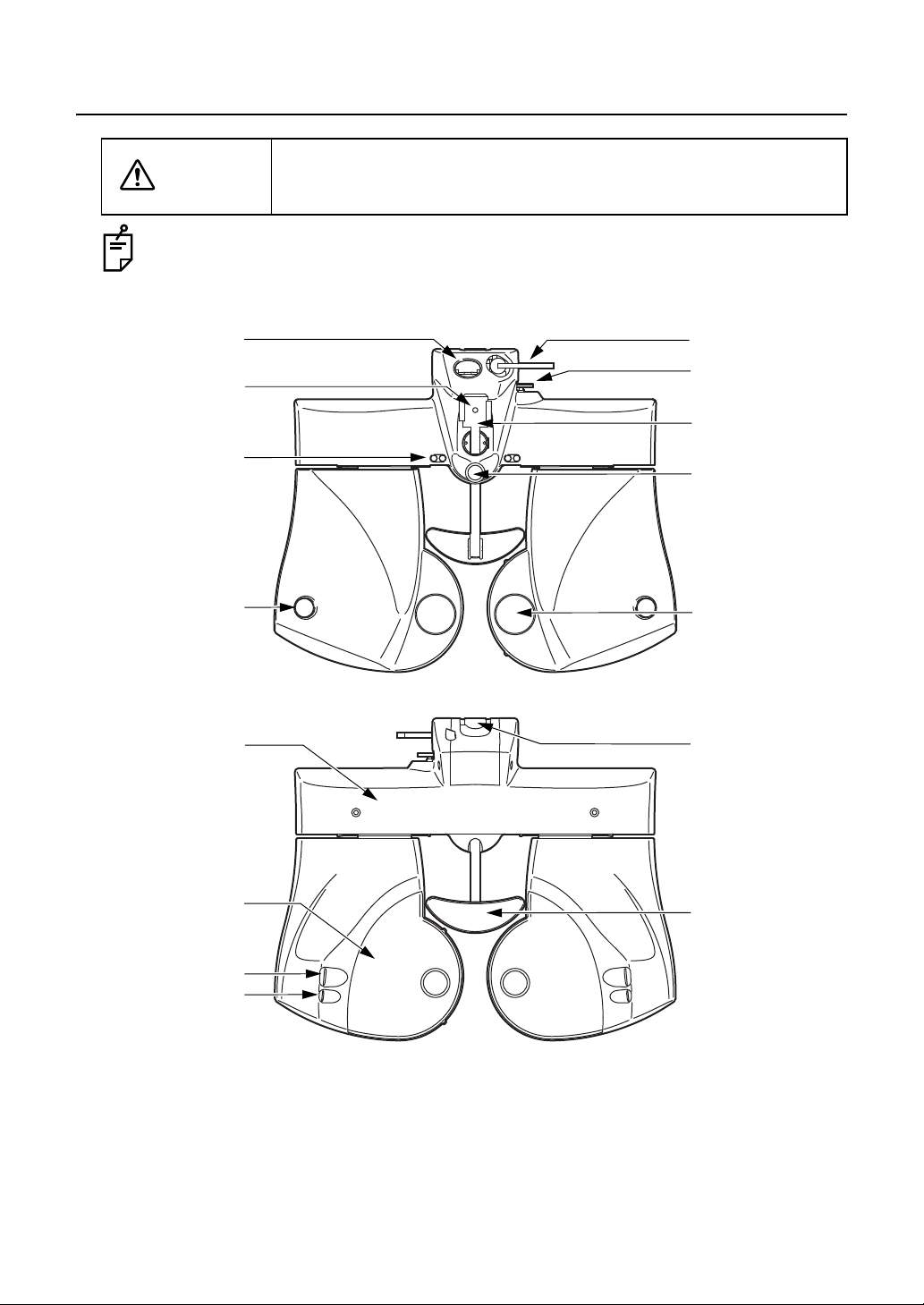
1.2.1 MAIN UNIT(Measuring head)
(1) Examination window ............... The patient's eyes are observed through this window, and
the display lenses are set here.
(2) Corneal vertex
distance window...................... The position of the patient's cornea can be observed
18
1. BEFORE USE
through this window.

(3) Forehead rest knob................. The position of the forehead rest can be adjusted by mov-
ing this knob backward/ forward.
(4) Leveling knob.......................... Levels the measuring head.
(5) Near-point rod holder.............. The near-point rod is inserted and attached here.
(6) Clamp screw ........................... Retains the near-point rod.
(7) Forehead rest.......................... The patient's forehead rests here.
(8) Cornea alignment scale .......... Measures the corneal vertex position.
(9) Level ....................................... Indicates the horizontal position for the level adjustment.
(10) Face shield.............................. The patient's face rests here.This cover can be removed.
(11) Cornea illumination ................. Illuminates the anterior eye segment to check the PD easily
even during examination in a dark room.
(12) Near-point illumination ............Illuminates the near-point target.
(13) Tilt locking lever ......................Adjusts the angle of the tilted measuring head and fixes it.
(14) Arm mounting shaft................. Mounts the instrument on the arm, etc.
(15) PD cover ................................. The cover for holding when tilting the head.
COMPOSITION OF PARTS WHICH CONTACT THE HUMAN BODY
Forehead rest : Polypropylene resin (Type B applied part)
Face shield : Polypropylene resin
19
1. BEFORE USE
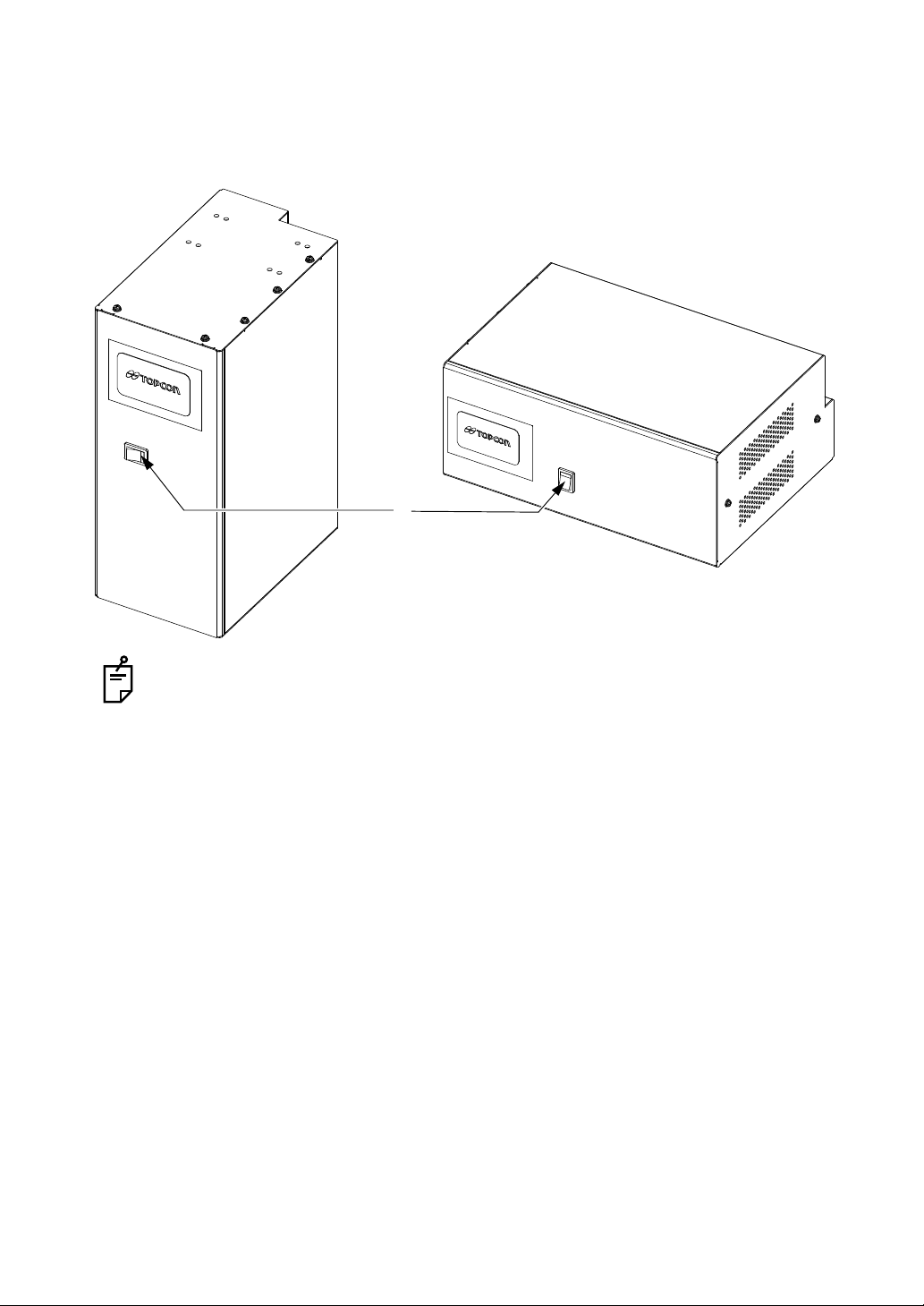
1.2.2 CV POWER SUPPLY UNIT WITH EXTERNAL PER-
(1)
SONAL COMPUTER (POWER SUPPLY UNIT)
Front surface
The orientation of the printer should be changed to match the type of installation.
(1) Power switch........................... Turns on/off the power.
20
1. BEFORE USE
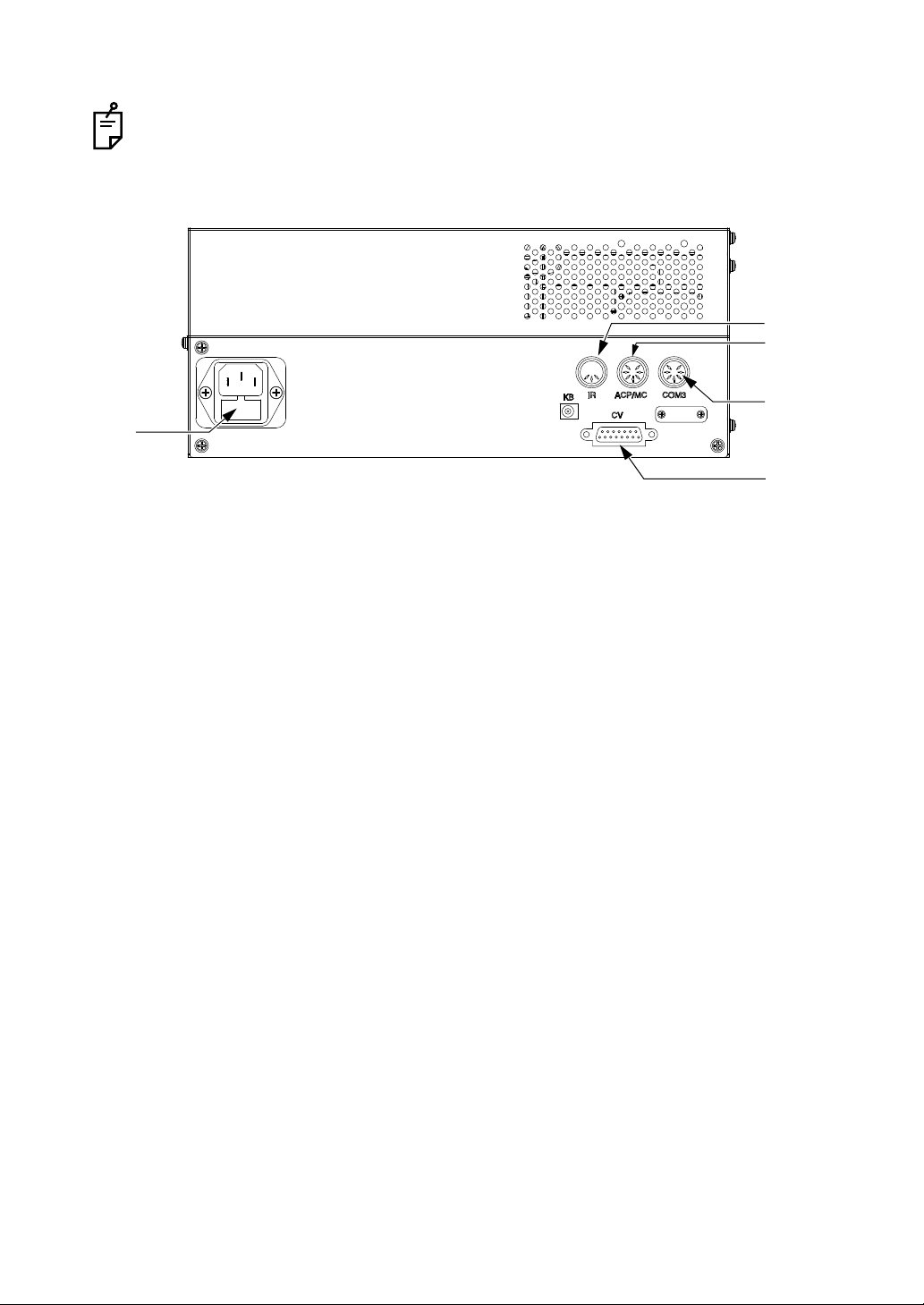
Rear panel
(3)
(4)
(5)
(6)
(2)
Only use the connector described in this chapter.
(2) Fuse holder............................. The fuse is set in this holder.
(3) IR connector............................ Used to connect the infrared communication unit (option).
(4) ACP/MC connector .................Used to connect the visual acuity chart with a serial con-
nection.
(5) COM3 connector..................... Used to connect a personal computer.
(6) CV connector .......................... Used to connect the measuring head.
21
1. BEFORE USE
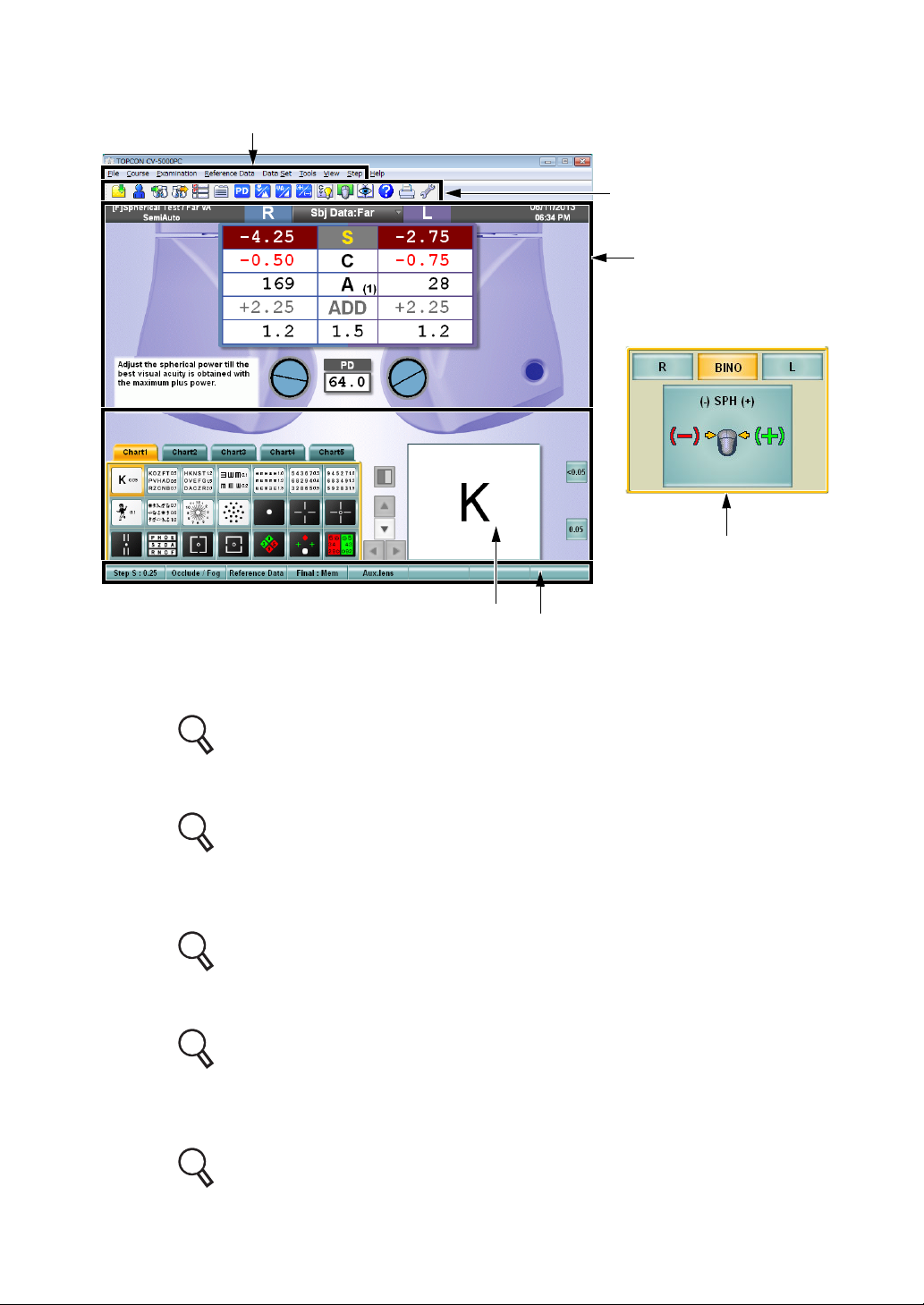
1.2.3 TEST SCREEN
(1)
(2)
(3)
(4)
(5)
(6)
(1) Menu bar
The menu for operation is displayed.
Refer to " MENU BAR/TOOLBAR" on P.23 for details.
(2) Toolbar
The buttons for operation are displayed.
Refer to " MENU BAR/TOOLBAR" on P.23 for details.
(3) Data display unit
The near- and far-point data, subjective and objective data, "Mini Help", etc. are displayed.
Refer to " DATA DISPLAY UNIT" on P.32 for details.
(4) Visual acuity chart operation unit
The chart page, the test chart icon, etc. are displayed.
Refer to " VISUAL ACUITY CHART OPERATION UNIT" on P.36 for details.
(5) Function button
The function selector buttons for the lens changing step, occlusion/fogging, etc. are
displayed.
Refer to " FUNCTION BUTTON" on P.36 for details.
22
1. BEFORE USE
(6) Control window
The buttons, mouse navigation and others for operation are displayed.
Refer to " FUNCTION BUTTON" on P.36 for details.
MENU BAR/TOOLBAR
You can access almost all functions from the menu bar. The buttons, which are frequently
used in tests, are displayed on the toolbar. Click each button, and you can use the indicated
function.
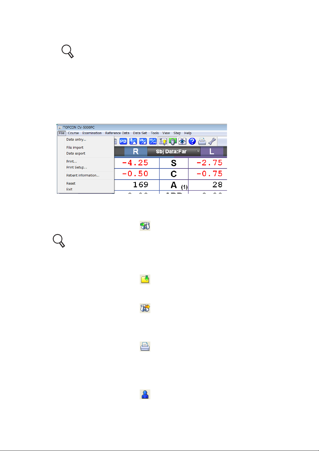
(1) File
• Data entry
The data of the connected device such as RM or CL is input.
This function is the same as the [ ] button ([Data entry] button) on the toolbar.
Refer to "6.1.3 IMPORTING THE DATA FROM OTHER DEVICES" on P.123 for
details.
• File import
The file data output from the external database software is captured.
This function is the same as the [ ] button ([File import] button) on the toolbar.
• Data export
Data are output through "Export".
This function is the same as the [ ] button ([Data export] button) on the toolbar.
• Print
The test results are printed.
It is possible to output data according to the setting.
This function is the same as the [ ] button ([Print] button) on the toolbar.
• Print Setup
Use this item to set a printer.
• Patient information
Edits the patient ID No./name/Age.
This function is the same as the [ ] button ([Patient information] button) on the toolbar.
23
1. BEFORE USE
• Reset
Sets the system to the initial test status again.
This function is the same as the [ ] button ([Reset] button) on the toolbar.
• Exit
Finishes the CV-5000PC software.
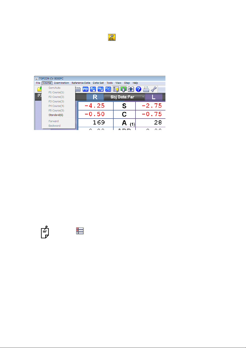
(2) Course
• SemiAuto
The "SemiAuto" mode is accessed.
• P1 Course (1) - P5 Course (5)
The test of P1 - P5 course starts.
• Standard
The test of "Standard" course starts.
• Forward
During the test of P1 - P5 or "Standard" course, the system shifts to the next step.
This function is the same as the [Forward] button on the control window.
• Backward
During the test of P1 - P5 or "Standard" course, the system returns to the preceding step.
This function is the same as the [Backward] button on the control window.
24
1. BEFORE USE
Click the [ ] button ([Course list] button) on the toolbar, and the list of the
registered courses is displayed. You can select a course from this list and start the
test.
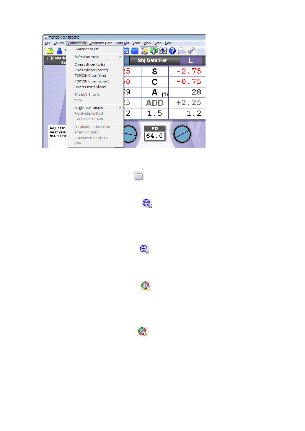
(3) Examination
• Examination list
The list of tests is displayed.
This function is the same as the [ ] button ([Examination list] button) on the toolbar.
• Cross cylinder (axis)
The cylinder axis measurement mode of cross cylinder test (Jackson cross) is accessed.
This function is the same as the [ ] button ([Cross cylinder (axis)] button) on the
toolbar.
• Cross cylinder (power)
The cylinder power measurement mode of cross cylinder test (Jackson cross) is
accessed.
This function is the same as the [ ] button ([Cross cylinder (power)] button) on the
toolbar.
• TOPCON Cross (axis)
The cylinder axis measurement mode of cross cylinder test (TOPCON cross) is accessed.
This function is the same as the [ ] button ([TOPCON cross (axis)] button) on the
toolbar.
• TOPCON Cross (power)
The cylinder power measurement mode of cross cylinder test (TOPCON cross) is
accessed.
This function is the same as the [ ] button ([TOPCON cross (power)] button) on the
toolbar.
• Smart Cross Cylinder
The smart cross test starts.
• Sheard's Criteria
The Sheard's criteria test starts.
You can also start this test with the function button after the phoria test.
25
1. BEFORE USE

• AC/A
The AC/A ratio test starts.
You can also start this test with the function button after the phoria test.
• Single ratio contrast
When a LC (liquid crystal) visual acuity chart is connected, it is possible to display a
contrast chart.
You can select the contrast from the following values.
100%, 50%, 25%, 12.5%, 10%, 5% and 2.5%
• Plural ratio contrast
When you connect a LC visual acuity chart and select a chart of 3 lines and 5 columns,
the characters are displayed from the left in the order of contrast 25%, 12.5%, 10%, 5%
and 2.5%.
• Exit contrast exam
Finishes the contrast test.
• Astigmatism simulation
When a LC visual acuity chart (excluding PC-50SB) is connected and the astigmatism
test chart is displayed, the astigmatism simulation is executed.
• Prism simulation
When a LC visual acuity chart is connected and the phoria test chart is displayed, the
phoria simulation is executed.
• Coincidence simulation
When a LC visual acuity chart is connected and the aniseikonia test chart is displayed,
the aniseikonia simulation is executed.
(4) Reference Data
• Show
The reference data is displayed.
• Hide
The reference data is hidden.
26
1. BEFORE USE
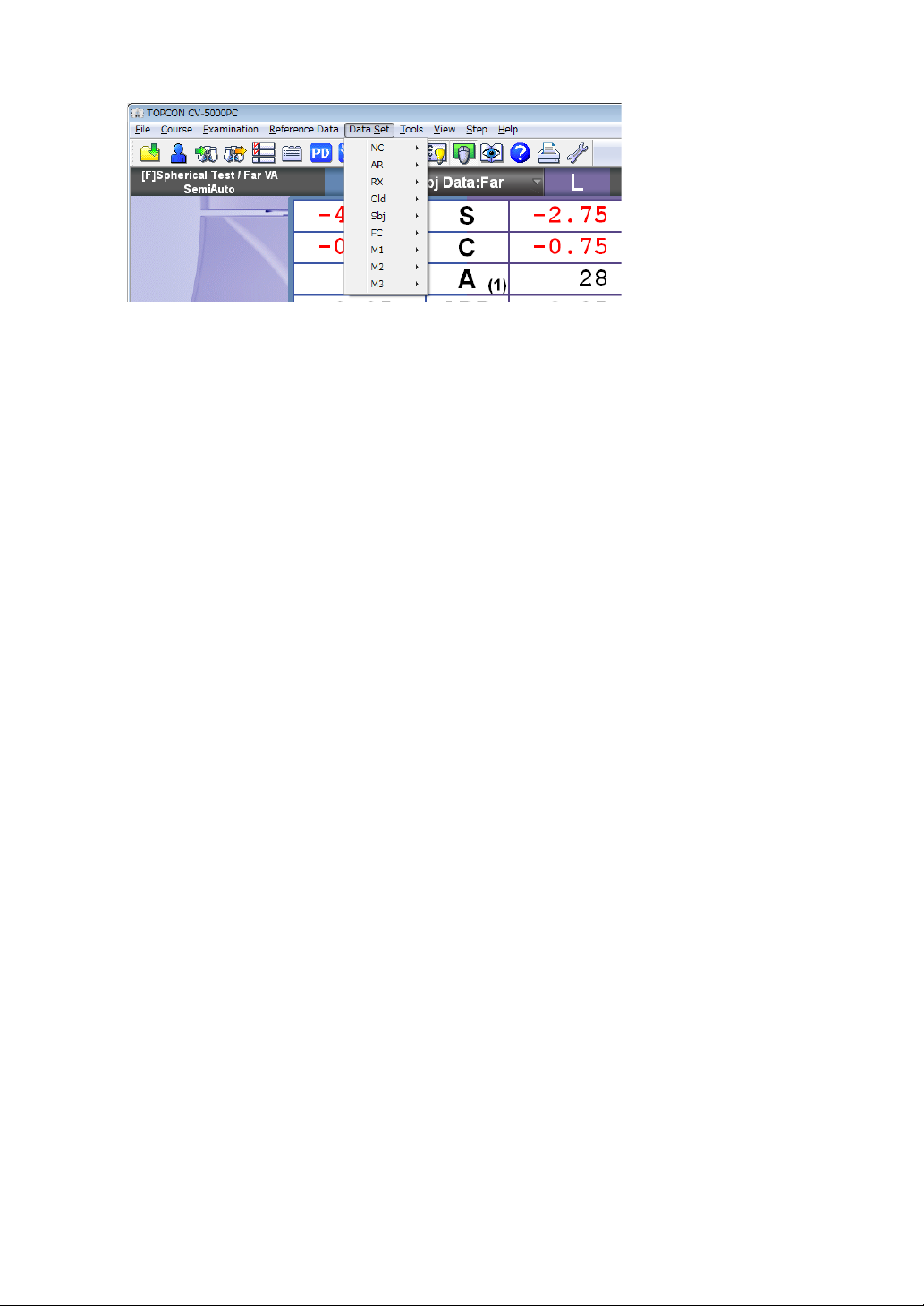
(5) Data Set
• NC
• Set :The unaided eye data is set and you can execute the comparison test.
• RM
• Set :The objective data is set and you can execute the comparison test.
• Memory :The selected data is stored as the objective data.
• CL
• Set :The eyeglass data is set and you can execute the comparison test.
• Memory :The selected data is stored as the eyeglass data.
• Old
• Set :The last prescription data is set and you can execute the comparison test.
• Memory :The selected data is stored as the last prescription data.
• Sbj
• Set :The subjective data is set and you can execute the comparison test.
• Memory :The selected data is stored as the subjective data.
• FC
• Set :The prescription data is set and you can execute the comparison test.
• Memory :The selected data is stored as the prescription data.
• M1
• Set :The M1 data is set and you can execute the comparison test.
• Memory :The selected data is stored as the M1 data.
• M2
• Set :The M2 data is set and you can execute the comparison test.
• Memory :The selected data is stored as the M2 data.
• M3
• Set :The M3 data is set and you can execute the comparison test.
• Memory :The selected data is stored as the M3 data.
27
1. BEFORE USE
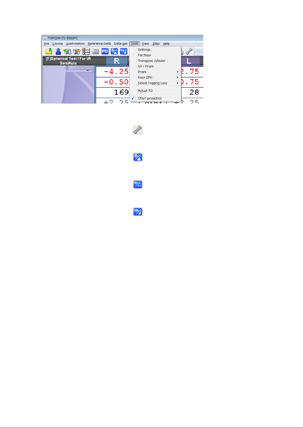
(6) Tools
• Settings
The settings menu is displayed.
This function is the same as the [ ] button ([Settings] button) on the toolbar.
• Far/Near
Changes the far- and near-point test modes each other.
This function is the same as the [ ] button ([Far/Near] button) on the toolbar.
• Transpose cylinder
Changes "+" and "-" of the cylinder power that is displayed on the main data.
This function is the same as the [ ] button ([Transpose cylinder] button) on the toolbar.
• VA/ Prism
Changes the displayed contents of the main data to the visual acuity/prism.
This function is the same as the [ ] button ([VA/Prism] button) on the toolbar.
• Prism
The side button functions in phoria test are displayed as the side menu.
• Mem + Clear
Stores the prism set in the measuring head and cancels the prism temporarily.
• Restore
Sets the stored prism data in the measuring head again.
• All Clear
Deletes the stored prism data and cancels the prism set in the measuring head.
• Base/Polar
Changes the notation of the prism refractive power.
• Near SPH
Sets the displayed data of the spherical power column on the main data in near-point test
mode.
• Far SPH
The far-point spherical power is always displayed on the main data in both far- and
near-point test modes.
• Near SPH
In near-point test mode, the near-point spherical power (far-point spherical power +
ADD) is displayed on the main data.
In far-point test mode, the far-point spherical power is displayed.
28
1. BEFORE USE

• Select Fogging Lens
You can change the occlusion type temporarily. It is possible to select a type from the
following items.
Close, +0.75D, +1.50D, +2.00D and Manual Fog
• Adjust PD
The mode to operate PD is accessed.
This function is the same as the [ ] button ([Adjust PD] button) on the toolbar.
• Chart projection
Turns ON/OFF the illumination of the visual acuity chart.
Test mode Function
Far-point test Turns ON/OFF the display of visual acuity chart.
Near-point test Turns ON/OFF the near-point illumination.
This function is the same as the [ ] button ([Chart projection] button) on the toolbar.
(7) View
• Aux. Lens
Changes "Show/Hide" of the auxiliary lens list.
• Help
Select the chart button and then this menu. The detailed "Help" is displayed on the chart
page.
Select this menu while "Help" is displayed, and the screen returns to the chart page.
This function is the same as the [ ] button ([Help] button) on the toolbar.
• Explanatory tool
The explanation tools are displayed.
This function is the same as the [ ] button ([Explanatory tool] button) on the toolbar.
Refer to "6.4.2 USING THE PATIENT EDUCATION TOOLS FOR THE PATIENT"
on P.151 for details.
1. BEFORE USE
29

• Control window
Changes "Show/Hide" of the control window.
This function is the same as the [ ] button ([Control window] button) on the toolbar.
Refer to " CONTROL WINDOW" on P.37 for details.
• Too lb ar
• Main
Changes "Show/Hide" of the main toolbar.
• Reset
Changes "Show/Hide" of the reset toolbar.
• Customize Toolbar
Refer to " CUSTOMIZE TOOLBAR" on P.194 for details.
• Status Bar
Changes "Show/Hide" of the status bar.
(8) Step
• SPH
Sets the spherical power changing step by operating the mouse. You can select the step
from the following items.
0.25D and 3.00D
• CYL
Sets the cylinder power changing step by operating the mouse. You can select the step
from the following items.
0.25D and 1.00D
• AXS
Sets the cylinder axis changing step by operating the mouse. You can select the step
from the following items.
1 and 5
In addition, you can set the cylinder axis to one of the following values.
0, 45, 90 and 135
30
1. BEFORE USE

• PRISM
Sets the prism changing step by operating the mouse. You can select the step from the
following items.
0.1, 0.2, 0.5 and 1.0
• PD
Sets the PD changing step by operating the mouse. You can select the step from the
following items.
0.5 and 1.0
(9) Help
• Version Information
Displays the version number and copyright.
31
1. BEFORE USE

DATA DISPLAY UNIT
(3)
(1)
(2)
(4)
(6)
(5) (6)
(3)
(1)-2 (1)-1 (1)-3
(1) Title bar
Displays the contents of the main data, test name, date and time.
(1)-1 Main data title
Displays the values in use and the far or near point test.
By clicking this tab, the list shown below will display.
Click the displayed list to select the data to be set in the measuring head.
Type Notation
Value in subjective measurement (CV-5000) Subjective
Objective value measured by RM, KR, etc. RM data
Eyeglass value measured by CL CL data
The refined power for the eyeglass that is prescribed
according to the value measured subjectively
The value without the correction lens Unaided
Last prescription data registered in database Old data
Data 1 stored in this instrument Memory1
Data 2 stored in this instrument Memory2
Data 3 stored in this instrument Memory3
32
1. BEFORE USE
Final data

(1)-2 Test name
(2)-1 (2)-3
(2)-4
(2)-2
Displays the current test and program
There are two types of programs to select from:
• Custom program :Click the [Course list] button to select. The measure-
ments can be performed in the sequence that was pro-
grammed .
• Semi-Auto program :By clicking the desired chart on the chart page, it will be
displayed. Measurements can be performed using each
chart individually.
For the custom program, the charts can be selected and customized by pressing [Settings]
Refer to "6.3.2 CUSTOMIZE THE TEST PROCEDURE" on P.146 for customizing the program course.
For the "Semi-Auto" course, each chart can be customized by [Settings]. To
customize the "Semi-Auto" course, change the test parameters registered in the
test chart icons.
Refer to "6.3.1 CUSTOMIZING THE CHART PAGE" on P.141 for details.
(1)-3 Time and lapse of test
Displays the date, time and lapse time since the test started. Only one of them
(date or lapse time since the test started) can be displayed by [Settings].
Refer to "8.2.7 Screen settings" on P.192.
(2) Main data
Displays the data and visual acuity value set in the measuring head.
33
1. BEFORE USE

(2)-1 Right eye data
Displays the lens data, which are set for the right eye of the measuring head.
Fit the mouse cursor to each area, and the value is highlighted. The value can
be changed by operating the mouse.
When the value is highlighted, you can enter a value directly through the keyboard.
The colors for the values of the spherical, cylinder and addition refractive powers are changed according to the value or occluding status.
(2)-2 Left eye data
Displays the data in the same way as the right eye.
(2)-3 Data item
The data items are displayed between the right and left eye data.
The changing step quantity of the mouse operation is displayed on [Function
button].
The step quantity of axis is displayed here in ( ).
In the far-point test, the addition refractive power item is shadowed, and in the
near point test, the spherical power item is shadowed.
The shadowed item cannot be selected.
Fit the mouse cursor to each item, and the both eyes values are highlighted.
The data of both eyes can be changed at the same time by operating the
mouse.
(2)-4 Visual acuity/prism
Displays the set visual acuity result or prism data.
If prism is shown by the base direction notation (XY), the refractive power of horizontal/vertical prism is displayed.
If prism is shown by the polar coordinate notation (r/), the refractive power and
angle of prism are displayed.
34
1. BEFORE USE
Refer to "8.2.7 Screen settings" on P.192 for changing the prism refractive power notation.

(3) Reference data
(3)-1
(3)-2
The objective data and lens data measured by the external devices are displayed for
comparison.
(3)-1 Reference data display area No.1
This data display area is used to compare or refer to data.
Click the title being requested, and the button list for RM Data or CL Data is displayed.
Click the item requested and the corresponding data will be displayed accordingly.
(3)-2 Reference data display area No.2
The function is the same as "Reference data display area No.1".
(4) Mini Help
Displays a simple explanation about the current test.
You can select "Displayed" or "Not displayed" by [Settings]. Refer to "8.2.7
Screen settings" on P.192 for details.
(5) PD
Displays the PD value. When you fit the mouse cursor to the PD value on the test
screen, the value is highlighted. You can change the value by operating the mouse.
The status generated by this operation is not the same as when clicking the
[Adjust PD] button. The cornea illumination is not turned on and the cross lens
is not set in the measuring head.
(6) Auxiliary lens
Displays the status of the auxiliary lens set in the measuring head, the cross cylinder
lens or TOPCON cross lens during the cylinder test. In addition, for the lens having
the axis in the open status, you can check the cylinder axis.
Click the auxiliary lens on the test screen, and it is possible to change the
occlusion.
Click the right mouse button, and it is possible to change the occlusion type.
Refer to " CHANGING THE AUXILIARY LENS" on P.130 for changing the
auxiliary lens.
Refer to " SELECTING THE TYPE OF OCCLUSION" on P.131 for changing
the occlusion.
35
1. BEFORE USE

VISUAL ACUITY CHART OPERATION UNIT
(1)
(2)
(3) (4)(4)
(1) Chart page
Click the test chart icon. The selected test chart will be shown on the test chart check
display section and the test relevant to the icon will start.
The mouse operation mode and auxiliary lens used in the test will be set automatically.
Click the right mouse button for the test chart icon. Only the chart is changed
without changing the test.
(2) Chart page selector tab
The test chart icons can be registered for up to five pages. You can change the chart
page by clicking the tab.
(3) Test chart check display
The test chart icon selected on the chart page is also displayed in another larger win-
dow once it has been selected. For the operation of the visual acuity test icon, the
character mask can be enabled by directly clicking the test chart.
(4) Side button
Use these auxiliary buttons, to access the necessary functions for the chart or test.
FUNCTION BUTTON
The displayed buttons are automatically changed depending on the function.
36
1. BEFORE USE

CONTROL WINDOW
Click the [Control window] button, and this is displayed.
The displayed buttons are changed to correspond to the functions.
Click the right or left mouse button on the mouse navigation, and it is possible to change the
value as displayed.
37
1. BEFORE USE

2. INSTALLATION
Level
Leveling knob
The service engineer must install the instrument. To make any changes or modify the connection,
contact your TOPCON dealer or the local TOPCON office listed on the back cover.
2.1 INSTALLING THE MEASURING HEAD
LEVEL ADJUSTMENT
Before using the instrument, check if it is horizontal, using the level. If the bubble is not
between the two red lines, turn the leveling knob to make the instrument horizontal.
INSTALLING AND REMOVING THE FACE SHIELD AND FOREHEAD REST
The face shield is attached by putting it on the face shield magnet properly.
To remove the forehead rest, when viewing from the side, pull it upward.
To mount the forehead rest, carry out the removal procedure in reverse.
38
2. INSTALLATION

ASSEMBLY/INSTALLATION OF NEAR-POINT ROD AND NEAR-
Near-point rod
Near-point card
POINT CARD
Insert the near-point card into the end of the near-point rod. The near-point card is designed to
slide on the near-point rod.
Insert the near-point rod into its holder and tighten the clamp screw securely. When the nearpoint rod is not in use, set it upright. (Tighten the clamp screw securely.)
CAUTION
NOTICE
NOTICE
To avoid injury due to contact, do not bring the patient’s face close to
the near-point rod.
The near-point card can be bent to only one direction. Do not bend it
forcefully in an other direction. The near-point card may be broken.
Install the near-point card to the near-point rod according to the seal,
which is adhered on the card to show its installation direction.
Install the near-point card toward the measuring head in the direction where it can be bent.
So that the card will swing downward after placing the near-point rod in the vertical position.
For the near-point card, refer to " ADJUSTMENT OF NEAR-POINT CARD" on P.139.
39
2. INSTALLATION

2.2 CONNECTING THE MEASURING HEAD, PERSONAL
(1)
(2)
Measuring head
(3)
Personal computer
COMPUTER
WARNING
CAUTION
CAUTION
This chapter will explain the procedure for connecting the measuring head and the personal computer to the power supply unit.
To avoid fire and electric shock in case of leakage, be sure to use a
grounded outlet. Do not connect to outlets that are not grounded.
To avoid electric shock, do not handle the plugs with wet fingers.
Do not to connect additional a power strip (it shall be not only in
patient environment also in outside of patient environment).
1 Make sure that the power switches of the power supply unit and the personal computer
are OFF.
2 As shown below, connect the measuring head, the personal computer and power cord to
the power supply unit.
(1) Measuring head connection cable
(2) Power cord
Refer to the instruction manual of your personal computer for connecting the
communication cable and the personal computer.
(3) Communication cable (DIN/D-sub)
3 Connect the power cord plug to a grounded outlet.
40
2. INSTALLATION
Item

2.3 CONNECTING THE VISUAL ACUITY CHART
Infrared communication unit
Visual acuity chart (ACP-8, MC-3)
Power supply unit
Image cable
Personal computer
Visual acuity chart
CAUTION
Install the visual acuity chart out of the CV-5000 patient's environment.
There are three types of the methods to connect the visual acuity chart. Use the connection
method applicable to the purchased chart.
CONNECTING A DEVICE TO RS-232C (ACP-8, MC-3.)
Communication cable (DIN/DIN)
or
Communication cable (DIN/D-sub)
Power supply unit
Visual acuity chart (ACP-8, MC-3)
CONNECTING A DEVICE TO INFRARED COMMUNICATION
(ACP-8, MC-3.)
CONNECTING A DVI DEVICE (PC-50S, PC-50SB, MC-4S)
Connect the image cable to the DVI terminal of the personal computer.
Refer to the instruction manual of your personal computer for details.
41
2. INSTALLATION

2.4 INSTALLATION OF CV-5000 SOFTWARE
1 Turn on the personal computer.
2 Insert the CV-5000 install CD to the optical drive of the personal computer.
The [CV-5000 Installer] screen starts.
3 Click the [Start Setup] button.
The setup screen of CV-5000 is displayed.
42
2. INSTALLATION

4 The setup screen of the CV-5000 software appears.
Place a check mark for "Create shortcut icon on the Desktop." The short cut is made on
the desktop.
Place a check mark for "Create shortcut icon on the Startup." The short cut is made on
"Startup".
Click the [Start Setup] button.
After the installation is completed, the setup screens of "CV-5000 Flash Tool", "IO Module", "PC-50S", "PC-50SB" and "MC-4S" are displayed without observing special order.
The screens of Step 5 - 9 are displayed without observing special order.
5 The setup screen of "CV-5000 Flash Tool" appears.
Click the [Start Setup] button.
43
2. INSTALLATION

6 The setup screen of "IO Module" appears.
Click the [Start Setup] button.
7 The setup screen of "MC-4S" appears.
Click the [Start Setup] button.
44
2. INSTALLATION

8 The setup screen of "PC-50S" appears.
Click the [Start Setup] button.
9 The setup screen of "PC-50SB" appears.
Click the [Start Setup] button.
45
2. INSTALLATION

10 Place a check mark for the language to be added. Then, click the [Start Setup] button.
The installation of the CV-5000 language module is executed.
When it is not necessary to add a language, click the [Cancel] button and proceed to the
next step.
After the installation is completed, the setup screen for updating the measuring head
firmware appears.
11 Select the serial communication port to which the CV power supply unit is connected
and click the [Connect] button.
Check the version and then click the [Start Setup] button.
The firmware of the measuring head is updated.
After the installation is completed, the setup screen for updating the CV power supply
unit firmware appears.
46
2. INSTALLATION

12 Select the serial communication port to which the CV power supply unit is connected
and click the [Connect] button.
Check the version and then click the [Start Setup] button.
The firmware of the CV power supply unit is updated.
13 Click the [OK] button.
The installation is completed.
47
2. INSTALLATION

2.5 SETTINGS OF DISPLAY PROPERTIES (ONLY WHEN A DVI DEVICE IS USED AS A VISUAL ACUITY CHART)
Set a display that is not a visual acuity chart as the main display.
1 Click the right mouse button on the desktop and select "Screen Resolution".
The "Change the appearance of your displays" window appears.
2 Click the [Identify] button.
3 Check the number displayed on the visual acuity chart.
4 According to the displayed number, select a display that is not a visual acuity chart from
the red frame.
5 When the selected display is set as the main display, "This is currently your main dis-
play." is shown.
48
2. INSTALLATION

6 When the selected display is not the main display, place a check mark for "Make this my
main display".
49
2. INSTALLATION

7 Click the [OK] button and close the window.
Example: When "1" is displayed on the personal computer monitor and, "2" on the visual
acuity chart:
Set the monitor of "1" as the main display.
The displayed monitor names and others are changed according to the hardware
configuration of the personal computer.
Refer to the instruction manual of the personal computer, graphic board or graphic
adapter for details.
50
2. INSTALLATION

2.6 INITIAL SETTINGS (REGISTERING THE VISUAL ACU-
ITY CHART OR OTHERS)
1 Turn on the power supply unit and start the CV-5000 software through the personal com-
puter.
The dialog box, which shows that the number of the COM port to be connected with the
CV system is not set, is displayed.
Click the [OK] button, and the "Initial Settings" screen appears.
2 Select a visual acuity chart to be connected.
Select "Device" (device name), "Type" (type name) and "Interface" (connection method)
of the distance visual acuity chart and "Device" (device name), "Type" (type name) and
"Near exam distance" of the near-point visual acuity chart.
51
2. INSTALLATION

When you select "IR control" as the connection type and click the [ ] but-
ton at the right, the test signal is sent to the visual acuity chart. This function
is convenient when checking that communication can be executed correctly
by the selected channel.
When you select "PC-50S", "PC-50SB" or "MC-4S" from the far-point chart
devices, "Interface" is changed to "Chart monitor selection". Click the [ ]
button at the right. You can check the monitor that corresponds to the name
in the "Chart monitor selection" list being displayed.
3 elect proper values for "Vertex distance", "Unit of exam distance" and "Visual acuity for-
mat".
"Vertex distance" and "Unit of exam distance" can also be set by "General settings".
For the details of each item, refer to P.167 ("Vertex distance") and P.168 ("Unit of exam
distance").
"Visual acuity format" can also be set by "Chart settings". For the details, refer to
P.177.
52
2. INSTALLATION

4 Select the port number of the connected personal computer on the column of "Serial port
for CV power supply unit".
Refer to the instruction manual of your personal computer for the port number of the
connected personal computer.
5 Click the [OK] button.
The test screen appears.
53
2. INSTALLATION

3. BASIC OPERATIONS
(Refer to "3.3".)
(Refer to "3.3".)
(Refer to "3.3".)
(Refer to "3.5".)
(Refer to "3.6".)
(Refer to "3.2.1".)
(Refer to "3.2.2".)
Turn on the power
Data input
Te st
Select the test chart and execute the test.
Select the program course and execute the test.
Select the test name and execute the test.
Printing
Resetting
CAUTION
To avoid electric shock, do not touch the external connection terminal
and the patient at the same time.
3.1 FLOW OF OPERATIONS
3.2 PREPARATION BEFORE MEASUREMENT
3.2.1 PREPARATION FOR TEST
1 Turn on the power and start the software.
2 Set the measuring head in front of the patient.
54
3. BASIC OPERATIONS
Press the power switches of the power supply unit and personal computer to turn on
them and start the CV-5000 software through the personal computer.
When you want to perform the tests on condition that the power is already ON,
start the CV-5000 software.
When the CV-5000 software has already started, click the [Reset] button to reset
the system.
Wipe the forehead rest, examination window and face shield prior to placing the patient
behind the instrument.

3 Click the [Adjust PD] button.
Forehead rest knob
Corneal aligning window
Examination window
The cornea illumination will illuminate the anterior segment of the patient.
The cross lens is set on the measuring head.
Have the patient view the far-point visual acuity chart.
4 Look into the front of the examination window from the operators side.
Operate the mouse to adjust the PD so that the pupil center of the patient is aligned with
the cross center.
When the pupil center is not aligned horizontally Operate the mouse to align the
pupil center with the center.
When one eye is not aligned vertically Ask the patient to move his/her face verti-
cally.
After aligning, click the [Adjust PD] button again to finish the PD adjustment.
5 Adjust the vertex distance (VD).
Look into the corneal aligning window. While watching the corneal alignment scale, turn
the forehead rest knob to adjust the distance between the patient's corneal vertex and
the lens to the desired value.
Refer to "9.3 CORNEAL ALIGNING DEVICE" on P.204 for details.
3. BASIC OPERATIONS
55

3.2.2 DATA INPUT
Input the patient's data to add it to the data list.
When TOPCON products such as RM, KR or CL are connected to the CV-5000, it is possible to read the data.
Refer to "6.1.3 IMPORTING THE DATA FROM OTHER DEVICES" on P.123 for details.
This chapter will explain how to input the measured values printed from the peripheral device
manually.
1 Click the right mouse button for the main data title. Then, click the button of the desired
data in the data list.
56
3. BASIC OPERATIONS

Click "Memory 1", "Memory 2" and "Memory 3" to save temporally the current
data. To save the data, input them first. Click the right mouse button for the
main data title to display the data list and then click the button of the input
data.
The data list (registration mode) displays the following data.
Example Meaning Operation by clicking
This data is being displayed as the main
data.
This is the data being displayed.
This data can be input
and saved.
This data cannot be
saved.
This is displayed as the main data
and it is possible to input the data.
Inactive
2 Input the value obtained from the peripheral device on the test screen.
Fit the mouse cursor to the data to be input and change the value by operating the
mouse.
If you want to input other data subsequently, select the desired data from the
data list and input it.
3 Return the main data to the subjective data.
Click the main data title and click the [Subjective] button in the data list.
If the subjective value is not changed after resetting, the data registered last is
copied as the subjective value.
4 Display the reference data.
If the reference data is not displayed on the screen, click the [Reference Data] button
from the function buttons.
The input data is displayed on the reference data display area.
57
3. BASIC OPERATIONS

5 Exchange the reference data.
Click the title bar of the reference data display area. Then, click the desired data in the
data list.
The selected data is displayed on the reference data display area.
58
3. BASIC OPERATIONS

3.3 TEST
Execute the test applicable to the patient.
SELECT THE TEST CHART AND EXECUTE THE TEST.
Select the test chart icon on the chart page and execute the test.
Click the test chart icon. The selected chart is displayed on the test chart check display area
and the test relevant to the icon starts.
The data, patient's eye and the auxiliary lens to be used in the test are automatically set.
When you select a test chart to execute the test, you can easily change the test order.
Arrange the test chart icons in the desired order from the upper left to the right and select them
in a left-to-right sequence. So, you can execute the tests in the desired order.
Refer to "6.3.1 CUSTOMIZING THE CHART PAGE" on P.141 for details.
SELECT THE PROGRAM COURSE AND EXECUTE THE TEST.
Register the test sequence and save it as a course. The tests are executed in the registered
order.
Even if you are in the program course, you can randomly execute another test, which is
not included in the course, by clicking the test chart icon on the chart page. In this case,
click the [Forward] button on the control window to restore the system to the original step
in the program course.
1 Click the [Course list] button.
The course selection window is displayed on the screen.
You can select the course registered by [Course registrations] on the "Settings" menu.
3. BASIC OPERATIONS
59

Refer to "6.3.2 CUSTOMIZE THE TEST PROCEDURE" on P.146 for [Course
registrations].
2 Click the course name.
3 Execute the test.
The first test step registered in the selected course is executed.
To advance to the next test, click the [Forward] button on the control window. Click the
[Backward] button on the control window, and the system returns to the previous test.
4 When the last test of the program course has been completed, the following message is
displayed.
To finish the program course, click the [YES] button.
SELECT THE TEST NAME AND EXECUTE THE TEST.
The specified test starts.
1 Click the [Examination list] button.
The test name selection window is displayed on the screen.
The test names are classified into three groups, [SCA], [Prism] and [Bino].
The test names can be selected by clicking the tab.
• SCA :Includes the tests to correct the spherical refraction, cylinder refraction and
binocular balance.
• Prism :Includes the phoria tests.
• Bino :Includes the binocular function tests excluding the phoria tests.
The displays of far- and near-point tests are changed by clicking the [Far/Near] button.
2 Click the test name.
60
3. BASIC OPERATIONS

3.4 PRESCRIPTION
Click the [Final: Mem] button from the function buttons to copy the subjective data to the Final data
and then modify the data if desired.
Refer to " RECORDING AND DISPLAYING THE PRESCRIPTION DATA" on P.137 for
setting the prescription data.
After setting the Final data, adjust the power for the final prescription.
3.5 OUTPUTTING THE RESULT
To print the test results through the printer connected to the personal computer, click the [Print]
button.
Refer to "6.4.1 DATA TO BE PRINTED" on P.150 for the output data.
In addition to the printing function, you can assign the following functions to the [Print] button:
Function to output the data through serial communication;
Function to output the file data.
Refer to "8.2.2 Function settings" on P.169 for details of the setting method.
3.6 RESETTING
After the test has been completed, click the [Reset] button.
The test screen, test chart and the measuring head are cleared and re-initialized. The system is
ready to conduct an examination for the next patient.
When further testing is not required, shut down the personal computer and turn off the
power supply unit.
61
3. BASIC OPERATIONS

4. GENERAL OPTOMETRY PROCEDURE
By making use of the measured values of RM or CL, you can perform an accurate subjective
refractive power measurement efficiently.
This section will explain the flow of the typical subjective refractive power measurement (far-point/
near-point) and the binocular (far-point phoria/near-point phoria) measurement.
4.1 DATA INPUT
Input the measured data of other devices manually or capture them automatically.
Refer to "3.2.2 DATA INPUT" on P.56 for manual input.
Refer to "6.1.3 IMPORTING THE DATA FROM OTHER DEVICES" on P.123 for auto-
matic capture.
4.2 FAR-POINT REFRACTIVE POWER MEASUREMENT
REFRACTIVE POWER MEASUREMENT BY USING CROSS CYLINDER
Click the [Couse list] button, and the list is displayed. The test sequence of the "Standard"
course on the list is shown below. The tests for "Checking the corrected visual acuity" are done
with the order of "Right eye - Left eye". "Binocular balance test" and after are done with both
eyes.
(1) Checking the spherical power: R/G test ......................... Refer to P.66.
(2) CC test (Cylinder axis/Cylinder power)............................ Refer to P.69, P.71 and P.73.
(3) Checking the spherical power: R/G test ......................... Refer to P.66.
(4) Checking the corrected visual acuity .............................. Refer to P.65.
(5) Binocular balance test ....................................................Refer to P.75, P.76 and P.78.
(6) Checking prescription visual acuity/prescription power ..Refer to P.137
62
4. GENERAL OPTOMETRY PROCEDURE

REFRACTIVE POWER MEASUREMENT USING ASTIGMATISM
TEST CHART
Clear the cylinder power and set only the spherical power in advance.
(1) Astigmatism chart test (Cylinder axis/Cylinder power) ....Refer to P.68.
(2) Checking the spherical power: R/G test ......................... Refer to P.66.
(3) Checking the corrected visual acuity .............................. Refer to P.65.
(4) Binocular balance test ....................................................Refer to P.75, P.76 and P.78.
(5) Checking prescription visual acuity/prescription power ..Refer to P.137.
4.3 NEAR-POINT REFRACTIVE POWER MEASUREMENT
Click the [Course list] button, and the list is displayed. The test sequence of the "Standard" course
on the list is shown below.
Prior to the near tests, conduct the far-point refractive power measurement.
(1) Binocular ADD measurement with cross grid ............Refer to P.107.
(2) Checking the near-point visual acuity ........................Refer to P.65
63
4. GENERAL OPTOMETRY PROCEDURE

4.4 BINOCULAR MEASUREMENT
FAR-POINT PHORIA
Start the test by using the result of the far-point refractive power refinement.
(1) Far-point vertical phoria measurement (Polarization cross test/Cross ring test/Prism
separation method) ........... Refer to P.80, P.82 and P.83.
(2) Far-point horizontal phoria measurement (Polarization cross test/Cross ring test/Prism
separation method) ........... Refer to P.80, P.82 and P.86.
(3) Refining the necessary prism power with the Sheard's criteria ...... Refer to P.105.
NEAR-POINT PHORIA
Start the test by using the result of the near-point refractive power refinement.
(1) Near-point vertical phoria measurement (Prism separation method) Refer to P.83.
(2) Near-point horizontal phoria measurement (Prism separation method) .. Refer to P.86.
(3) Refining the necessary prism power with the Sheard's criteria ..... Refer to P.105.
64
4. GENERAL OPTOMETRY PROCEDURE

5. OPERATION FOR TESTS
This chapter will explain the tests and operations that can be performed with the CV-5000 instrument.
This manual will explain the operation when the ACP-8 (A) is used as the far-point chart
and NC-3 (E), as the near-point chart in the test.
5.1 VISUAL ACUITY TEST/SPHERICAL POWER/CYLIN-
DER POWER CORRECTION
5.1.1 VISUAL ACUITY MEASUREMENT
Measure the patient's visual acuity.
1 Select a visual acuity chart.
To perform the visual acuity measurement, select the visual acuity chart icon from the
chart page.
In near-point test, select a proper target from the near-point card targets manually.
Example of the test chart icons on chart page
Far-point
chart
ACP-8(A) NC-3(E)
Far-point test chart icon Near-point
chart
Near-point test chart icon
65
5. OPERATION FOR TESTS

The following items are automatically changed as shown below.
When the mouse operation mode
is set to "Spherical power"
When the mouse operation mode is set to "ADD"
Item Description
The test is perfomed with rigth eye, left eye or both eyes.
Test eye
Auxiliary lens Not set.
Mouse operation
mode
Mouse Navigation
When the test chart is selected, the status of last test is succeeded.
In far-point test, the mode to operate the spherical power is
set.
In near-point test, the mode to operate ADD is set.
2 Measure the visual acuity.
Measure the patient's visual acuity.
To display the visual acuity test chart having the different visual acuity values in far-point
test, select a test chart again on the chart page or click [ ] and [ ] buttons. In nearpoint test, rotate the near-point card targets to select a corresponding acuity chart.
3 Record the visual acuity value.
Click the button applicable to the patient's visual acuity among the side buttons. The
value is recorded as the patient's visual acuity.
Each time you click the visual acuity button, the recorded value is overwritten for correction purposes.
For the visual acuity value button, refer to " SETTING THE VISUAL ACUITY
VALUE DIRECTLY" on P.132.
5.1.2 R/G TEST
Measure the spherical refraction for the patient.
1 Fog the patient's eye.
To make use of the fogging method, operate the mouse to shift the spherical power to
the plus side in the amount of fogging power desired.
It is possible to preset the fogging quantity when the R/G test chart is selected.
Set the fogging quantity on the parameter setting screen. To access the parameter setting screen, select "Settings", "Chart settings", "Chart page registration"
and click the [Modify] button.
5. OPERATION FOR TESTS
66

2 Select the R/G test chart.
When the mouse operation mode
is set to "Spherical power"
When the mouse operation mode is set to "ADD"
To perform the R/G test, select the R/G test chart icon on the chart page.
In near-point test, set a proper target from the near-point card targets manually.
Example of the test chart icons on chart page
Far-point
chart
ACP-8(A) NC-3(E) -
The following items are automatically changed as shown below.
Item Description
Test eye
Auxiliary lens Not set.
Mouse operation
mode
Mouse Navigation
Far-point test chart icon Near-point
chart
The test is performed with right eye, left eye and both eyes.
When the test chart is set, the last status is succeeded.
In far-point test, the mode to operate the spherical power is
set.
In near-point test, the mode to operate ADD is set
Near-point test chart icon
3 Correct the spherical power.
Ask the patient which side the characters are seen better, on the red or green side.
When the characters on the red side are seen better, click the "R" button for the mouse
navigation. When the characters on the green side are seen better, click the "G" button.
Adjust until the characters on both sides are seen equally.
67
5. OPERATION FOR TESTS

5.1.3 ASTIGMATISM TEST
Search for the approximate astigmatic correction value of the patient.
1 Prepare for the test.
Before beginning this test, carry out the following operation:
Set the cylinder axis "180" and cylinder power "0.00". Perform fogging in the plus direction and then shift the power in the minus direction. Adjust the spherical power to the
lowest so that the visual acuity may be 0.5 to 0.6 (20/40 to 20/30, 6/18 to 6/9).
2 Select the astigmatism test chart.
To perform the astigmatism test, select the astigmatism test chart icon on the chart page.
In the near-point test, select the proper target from the near-point card targets manually.
Example of the test chart icons on chart page
Far-point
chart
ACP-8(A) NC-3(E)
The following items are automatically changed as shown below.
Item Description
Test eye
Auxiliary lens Not set.
Mous operation
mode
Mouse Navigation
Far-point test chart icon Near-point
chart
When any other item except "binocular" is the last test object,
the status of last test is succeeded. When "binocular" are the
last test object, the right eye of the patient is selected.
The mode to operate the cylinder axis is set.
Near-point test chart icon
68
5. OPERATION FOR TESTS

3 Correct the cylinder axis.
If the mouse operation mode is not set for "Cylinder axis", click the [Power/Axis] button
on the control window to change the mode.
Ask the patient whether he/she sees a darker bolder line than others. If there is no such
line, the patient does not have astigmatism. If he/she sees a darker bolder line, have
him/her answer with the numerals between 1 and 6. Operate the mouse to set "The
numeral of the answer x 30" to the cylinder axis. The cylinder axis is changed to the
positive direction by clicking the "+" button for the mouse navigation and, to the negative
direction by clicking the "-" button.
4 Correct the cylinder power.
Click the [Power/Axis] button to change the mouse operation mode to "Cylinder power".
Change the cylinder power until all the lines are seen with equal clarity. The cylinder
power is changed to the positive direction by clicking the "+" button for the mouse navigation and, to the negative direction by clicking the "-" button.
5.1.4 CROSS CYLINDER TEST (JACKSON CROSS)
Measure the patient's astigmatism accurately by using the Jackson cross cylinder lens.
1 Prepare for the test.
Before beginning this test, adjust the spherical power so that the characters on the red
and green sides are seen equally in the R/G test. Additionally, set the cylinder power/
axis measured objectively or execute the astigmatism test to set the approximate cylinder power/axis.
For the R/G test, refer to "5.1.2 R/G TEST" on P.66.
For the astigmatism test, refer to "5.1.3 ASTIGMATISM TEST" on P.68.
2 Select the cross cylinder test chart.
To perform the cross cylinder (Jackson cross) test, select the cross cylinder test chart
icon on the chart page.
After selecting the test chart, if the test name is not "[F] Jackson Cross Cylinder" at the
upper left on the screen, click the [Jackson CC] button or [Manual CC] button from the
function buttons.
Example of the test chart icons on chart page
Far-point
chart
ACP-8(A) NC-3(E) -
Far-point test chart icon Near-point
chart
Near-point test chart icon
5. OPERATION FOR TESTS
69

The following items are automatically changed as shown below.
[Cross cylinder: Reverse]
button
Item Description
When any other item except "binocular" is the last test object,
Test eye
Auxiliary lens
Mouse operation
mode
Mouse Navigation
the status of last test is succeeded. When "binocular" are the
last test object, the right eye of the patient is selected.
The Jackson cross cylinder lens is
selected for the eye being tested.
The green and red frames around the
lens indicate the front and rear of the
cross cylinder.
The mode to operate the cylinder axis is set.
3 Measure the cylinder axis.
Click the [Cross cylinder: Reverse] button on the control
window. Have the patient answer which frame he/she can
see the chart better, on the red or green side.
When the chart is seen better with the green frame, click
the "G" button for the mouse navigation. When the chart is
seen better with the red frame, click the "R" button.
Make adjustments until the patient sees the chart almost
equally with both red and green frames.
4 Measure the cylinder power.
After measuring the cylinder axis, proceed to the cylinder power measurement.
To proceed to this measurement, click the [Power/Axis] button on the control window.
The procedure is the same as the cylinder axis measurement. Make adjustments until
the patient sees the chart almost equally through the CC lens having red or green frame.
Click the [Power/Axis] button. The system returns to the cylinder axis measurement
mode.
70
5. OPERATION FOR TESTS

5.1.5 CROSS CYLINDER TEST (TOPCON CROSS)
Measure the patient's astigmatism accurately by using the TOPCON cross
cylinder lens. The TOPCON cross cylinder lens is made so that the front
and rear of the Jackson cross cylinder lens can be viewed at the same time.
By seeing the green and red in the periphery around the lens, you can check
the views of the front and rear at the same time.
1 Prepare for the test.
Before beginning this test, adjust the spherical power so that the characters on the red
and green sides may be seen equally in the R/G test. Additionally, set the cylinder
power/axis measured objectively or execute the astigmatism test to set the approximate
cylinder power/axis.
For the R/G test, refer to "5.1.2 R/G TEST" on P.66.
For the astigmatism test, refer to "5.1.3 ASTIGMATISM TEST" on P.68.
2 Select the cross cylinder test chart.
To perform the cross cylinder (TOPCON cross) test, select the cross cylinder test chart
icon on the chart page. Then, click the [Topcon CC] button from the function buttons.
Example of the test chart icons on chart page
Far-point
chart
ACP-8(A) NC-3(E) -
Far-point test chart icon Near-point
chart
Near-point test chart icon
71
5. OPERATION FOR TESTS

The following items are automatically changed as shown below.
Item Description
When any other item except "binocular" is the last test object,
Test eye
Auxiliary lens
the last status is succeeded. When "binocular" are the last
test object, the right eye of the patient is selected.
The TOPCON cross cylinder lens is set to the
test eye.
Mouse operation
mode
Mouse Navigation
The mode to operate the cylinder axis is set.
3 Measure the cylinder axis.
Have the patient answer which frame side on the CC lens he/she can see better, on the
red or green side.
When the chart is seen better with the green frame, click the "G" button for the mouse
navigation. When the chart is seen better with the red frame, click the "R" button.
Make adjustment until the patient sees the green and red frame sections almost equally.
4 Measure the cylinder power.
After measuring the cylinder axis, proceed to the cylinder power measurement.
To proceed to this measurement, click the [Power/Axis] button on the control window.
The procedure is the same as the cylinder axis measurement. Make adjustment until
the patient sees the chart almost equally through the CC lens having red and green
frames.
Click the [Power/Axis] button. The system returns to the cylinder axis measurement.
72
5. OPERATION FOR TESTS

5.1.6 SMART CROSS TEST
Image of the cylinder axis
move during test
(Temporary-real value)
Measure astigmatism accurately with the Jackson cross cylinder lens semi-automatically.
In general, the cross cylinder test forces the patient to compare
the targets having slightly different powers repeatedly. Consequently the patient becomes tired from stress.
In the smart cross test, the cylinder power and axis, which are
input as the initial values, are regarded as the "Temporary-real
values". By referring to the temporary-real axis value, the system calculates the axis whose view is most different on the front
and rear of the cross cylinder lens. First, the patient's comparison begins with this calculated axis. Then, the axis is moved to
the opposite side against the temporary real value and the system asks the patient to compare the views of the chart. The
axis movement is automatically conducted. As the move width
is made smaller, the system searches for the "Real cylinder
axis". This test is performed to reduce the fatigue on the
patient.
At the final stage of the axis test, the type of the used cross cylinder lens is automatically changed from "0.50D" to "0.25D"
to reduce uneasiness of the patient. The test finishes with a lower cross-cylinder power resulting
in a clearer end result and less fatigue for the patient.
1 Prepare for the test.
In some cases, measurement cannot be done. Before beginning the test, set the cylinder power and axis measured objectively.
2 Select the cross cylinder test chart.
Select the cross cylinder test chart icon on the chart page. Then, click the [Smart CC]
button from the function buttons.
Far-point
chart
ACP-8(A) NC-3(E) -
Example of the test chart icons on chart page
Far-point test chart icon Near-point
chart
Near-point test chart icon
73
5. OPERATION FOR TESTS

The following items are automatically changed as shown below.
[Cross cylinder: Reverse]
button
Item Description
When any other item except "binocular" is the last test object,
Test eye
Auxiliary lens
the last status is succeeded. When "binocular" are the last
test object, the right eye of the patient is selected.
The Jackson cross cylinder lens is set
to the test eye. The green and red
frames around the lens indicate the
front and rear of the cross cylinder.
Mouse operation
mode
Mouse Navigation
The mode to operate the cylinder axis is set.
3 Perform measurement.
Click the [Cross cylinder: Reverse] button on the control
window. Have the patient answer which frame the chart is
seen better, red or green.
When the chart is seen better with the green frame, click
the [Red<Green] button on the mouse navigation. When
the chart is seen better with the red frame, click the
[Red>Green] button. When the chart is seen equally with
the green and red frames, click the [Red=Green] button.
Repeat the above operation until the test is finished.
The program operates the cylinder axis and power and changes the tests automatically.
When the test is finished, the message "This exam has been finished." is displayed.
74
5. OPERATION FOR TESTS

5.1.7 BALANCE TEST (POLARIZATION)
To make the patient's binocular vision clear, adjust the spherical power according to the visual
acuity balance of each eye.
1 Select the balance test (polarization) chart.
To perform the balance test (polarization), select the balance test (polarization) chart
icon on the chart page.
Example of the test chart icons on chart page
Far-point
chart
ACP-8(A) NC-3(E) -
The following items are automatically changed as shown below.
Item Description
Test eye Changed to the binocular mode.
Auxiliary lens
Mouse operation
mode
Mouse Navigation
Far-point test chart icon Near-point
chart
The polarized filter is set.
The mode to operate the spherical power is selected.
Near-point test chart icon
75
5. OPERATION FOR TESTS

2 Adjust the balance.
Adjust the visual acuity balance between the right and left eyes.
The patient sees the upper row of letters with the right eye and the lower row of letters
with the left eye. Have the patient compare the top and bottom row of letters and answer
which row of letters is seen better, upper or lower.
When he/she sees better with the right eye, click the [R] button on the control window.
When he/she sees better with the left eye, click the [L] button. Then, click the "+" button
for the mouse navigation to add "+0.25D" to the spherical power.
In this state, have the patient compare the top and bottom row of letters again.
Finish the test in one of the following situations:
When the upper and lower row of letters are seen equally;
The test results just before the eye that sees better has been changed.
5.1.8 BALANCE TEST (POLARIZATION: 2-COLOR)
To make the patient's binocular vision clear, adjust the spherical power so that the refind end point
of each eye will be equal when the patient sees an object with both eyes.
1 Select the balance test (polarization: 2-color) chart.
To perform the balance test (polarization: 2-color), select the balance test (polarization:
2-color) chart on the chart page.
Example of the test chart icons on chart page
Far-point
chart
ACP-8(A) NC-3(E) -
Far-point test chart icon Near-point
chart
Near-point test chart icon
76
5. OPERATION FOR TESTS

The following settings are automatically changed as shown below.
Item Description
Test eye Changed to the binocular mode.
The polarized filter is set.
Auxiliary lens
Mouse operation
mode
Mouse Navigation
The mode to operate the spherical power is selected.
2 Check the refined status of the right eye.
Adjust the refined status of the right eye on condition that the patient sees the chart binocularly. Click the [R] button on the control window.
The patient sees the squares arranged in the vertical direction with the right eye and, the
ones in the horizontal direction with the left eye.
First, have the patient compare the characters of the red and green squares in the vertical direction and answer which square the character is seen better, on the red or green
side. When the characters in the red square are seen better, click the "R" button for the
mouse navigation. When the characters in the green square are seen better, click the
"G" button.
In this state, have the patient compare and answer again.
When the characters in the vertical direction are seen almost equally, the refinement of
the right eye is finished.
3 Check the adjusted status of the left eye.
Click the [L] button on the control window.
Following the same procedure as the right eye, have the patient compare the characters
of the squares arranged in the horizontal direction to check the refined status of the left
eye.
When the characters in the horizontal position are seen almost equally, the adjustment
of the left eye is finished.
4 Check the adjusted status of both eyes.
Click the [BINO] button on the control window.
Following the same procedure as mentioned prior, have the patient compare the characters of the red and green squares in the up-and-down and right-and-left directions to
check the adjusted status of both eyes.
When the characters in the green and red squares are seen almost equally through the
whole process, the test is finished.
5. OPERATION FOR TESTS
77

5.1.9 BALANCE TEST (PRISM)
To make the patient's binocular vision clear, adjust the spherical power according to the visual
acuity balance of each eye. The only difference compared to the "Balance test (Polarization)" is
that a general visual acuity chart is used as the test chart.
1 Select "[F] Bino. Balance (Prism)" from "Examination list".
To execute this test, specify the test name from "Examination list".
Click the [Examination list] button to display "Examination list".
Click the [SCA] tab and select "[F] Bino. Balance (Prism)" from the displayed list.
To perform the near-point test, select the test chart icon shown below.
Far-point
chart
ACP-8(A) - NC-3(E)
In the far-point test, the chart where the characters are arranged on one horizontal line
or the visual acuity chart to which the horizontal mask is applied is set.
In near-point test, select the corresponding chart from the near-point card targets manually.
Far-point test chart icon Near-point
chart
Near-point test chart icon
78
5. OPERATION FOR TESTS

The following settings are automatically changed as shown below.
When the mouse operation mode
is set to "Spherical power"
When the mouse operation mode is set to "ADD"
Item Description
Test eye Changed to the binocular mode.
The base-up prism of "6 prism" is set
to the right eye.
Auxiliary lens
Mouse operation
mode
Mouse Navigation
In far-point test, the mode to operate the spherical power is
selected.
In near-point test, the mode to operate ADD is selected.
(The left illustrations are the status as
seen from the user side as the CV5000 software screen.)
2 Adjust the balance.
Adjust the visual acuity balance between the right and left eyes.
The image the patient sees is separated top and bottom because of the prism inserted at
the right eye. The patient sees the upper section with the right eye and the lower section
with the left eye. Have the patient compare which section is seen better, upper or lower.
When he/she sees better with the right eye, click the [R] button on the control window.
When he/she sees better with the left eye, click the [L] button. Then, click the "+" button
for the mouse navigation to add "+0.25D" to the spherical power.
In this state, have the patient compare the upper and lower sections again.
Finish the test in one of the following situations:
When the upper and lower sections are seen equally;
The test results just before the eye that sees better has been changed.
79
5. OPERATION FOR TESTS

5.2 PHORIA TEST
When the mouse operation mode
is set to "Horizontal prism"
When the mouse operation
mode is set to "Vertical prism"
5.2.1 PHORIA TEST (POL. CROSS)
Measure heterophoria of the patient by using the "Pol. Cross" chart.
1 Select the "Phoria Test (Pol. Cross)" chart.
To perform "Phoria Test (Pol. Cross)", select the "Phoria Test (Pol. Cross)" chart icon on
the chart page.
Example of the test chart icons on chart page
Far-point
chart
ACP-8(A) NC-3(E) -
The following settings are automatically changed as shown below.
Item Description
Test eye
Auxiliary lens
Mouse operation
mode
Far-point test chart icon Near-point
chart
Changed to the binocular mode.
When the mouse operation mode is set to "Horizontal prism",
the left eye is the object of the mouse operation.
When the mouse operation mode is set to "Vertical prism",
the right eye is the object of the mouse operation.
The polarized filter is selected.
In initial status, the mode to operate "Horizontal prism" is set.
Near-point test chart icon
Mouse Navigation
80
5. OPERATION FOR TESTS

2 Check if the patient has heterophoria.
When the patient sees the test chart through the polarized filter, only the vertical lines
are seen with the right eye and only the horizontal lines, with the left eye.
If the patient does not have heterophoria, he/she sees the vertical line crossing the horizontal line at the center.
If the patient has horizontal phoria, the vertical and horizontal lines are disassociated in
the horizontal direction in his/her vision.
If the patient has vertical phoria, the vertical and horizontal lines are disassociated in the
vertical direction in his/her vision.
3 Measure the horizontal phoria value.
If the patient has horizontal phoria, measure its value.
If the mouse operation mode is not set to "Horizontal prism", click the [H/V] button on the
control window to change the mode.
Ask the patient which direction the vertical line is in relation to the horizontal line, right or
left.
When the vertical line is disassociated to the left, click the left mouse button for the
mouse navigation until the vertical line reaches the center.
When the vertical line is disassociated to the right, click the right mouse button for the
mouse navigation until the vertical line reaches the center.
4 Measure the vertical phoria value.
If the patient has vertical phoria, measure its value.
Click the [H/V] button on the control window to change the mouse operation mode to
"Vertical prism".
Ask the patient which direction the horizontal line is in relation to the vertical line, upward
or downward.
When the horizontal line is disassociated upward, click the left mouse button for the
mouse navigation until the horizontal line reaches the center.
When the horizontal line is disassociated downward, click the right mouse button for the
mouse navigation until the horizontal line reaches the center.
81
5. OPERATION FOR TESTS

5.2.2 PHORIA TEST (CROSS RING)
When the mouse operation mode
is set to "Horizontal prism"
When the mouse operation
mode is set to "Vertical prism"
Measure heterophoria of the patient by using the "Cross Ring" chart.
1 Select the "Phoria Test (Cross Ring)" chart.
To perform a "Phoria Test (Cross Ring)", select the "Phoria Test (Cross Ring)" chart icon
on the chart page.
Example of the test chart icons on chart page
Far-point
chart
ACP-8(A) NC-3(E) -
The following settings are automatically changed as shown below.
Item Description
Test eye
Auxiliary lens
Mouse operation
mode
Far-point test chart icon Near-point
chart
Changed to the binocular mode.
When the mouse operation mode is set to "Horizontal prism",
the left eye is the object of the mouse operation.
When the mouse operation mode is set to "Vertical prism",
the right eye is the object of the mouse operation.
The red lens is set to the right eye and
the green lens, to the left eye.
(The left illustrations are the status as
seen from the operator side as the
CV-5000 software screen.)
In initial status, the mode to operate "Horizontal prism" is set.
Near-point test chart icon
Mouse Navigation
82
5. OPERATION FOR TESTS

2 Check if the patient has heterophoria.
When the patient sees the test chart through the red and green lenses, only the cross is
seen with the right eye and only the ring, with the left eye.
If the patient does not have heterophoria, the cross center overlaps the ring center in his/
her vision.
If the patient has horizontal phoria, the centers of cross and ring are disassociated in the
horizontal direction in his/her vision.
If the patient has vertical phoria, the centers of cross and ring are disassociated in the
vertical direction in his/her vision.
3 Measure the horizontal phoria value.
If the patient has horizontal phoria, measure its value.
If the mouse operation mode is not set to "Horizontal prism", click the [H/V] button on the
control window to change the mode.
Ask the patient which direction the cross is in relation to the ring, right or left.
When the cross is disassociated to the left against the ring, click the left mouse button
for the mouse navigation until the vertical center lines of cross and ring overlap each
other.
When the cross is disassociated to the right against the ring, click the right mouse button
for the mouse navigation until the vertical center lines of cross and ring overlap each
other.
4 Measure the vertical phoria value.
If the patient has vertical phoria, measure its degree.
Click the [H/V] button on the control window to change the mouse operation mode to
"Vertical prism".
Ask the patient which direction the cross is disassociated in relation to the ring, upward
or downward.
When the cross is disassociated downward in relation to the ring, click the left mouse
button for the mouse navigation until the horizontal center lines of cross and ring overlap
each other.
When the horizontal line is disassociated upward in relation to the ring, click the right
mouse button for the mouse navigation until the horizontal center lines of cross and ring
overlap each other.
5.2.3 PHORIA TEST (MADDOX)
Measure heterophoria of the patient by using the fixation target and Maddox rod.
1 Prepare for the test.
The measurement of this test cannot be conducted correctly in a bright room. Perform
this test in a semi-dark room.
When you use the TOPCON visual acuity charts, ACP-8 and MC-3, the fixation target is
displayed. The fixation target may noy provide the luminance required for the test as the
dot light source depending on the lighting of the test room. In this case, utilize a sufficient light source such as a penlight.
5. OPERATION FOR TESTS
83

2 Select the "Phoria Test (Maddox)" chart.
When the mouse operation mode
is set to "Horizontal prism"
When the mouse operation
mode is set to "Vertical prism"
To perform "Phoria Test (Maddox)", select the fixation target chart icon on the chart
page.
Example of the test chart icons on chart page
Far-point
chart
ACP-8(A) NC-3(E) -
The following settings are automatically changed as shown below.
Item Description
Test eye
Auxiliary lens
Far-point test chart icon Near-point
chart
Changed to the binocular mode.
When the mouse operation mode is set to "Horizontal prism",
the left eye is the object of the mouse operation.
When the mouse operation mode is set to "Vertical prism",
the right eye is the object of the mouse operation.
When the mouse operation mode is
set to "Horizontal prism", the horizontal Maddox rod lens is set to the right
eye.
When the mouse operation mode is
set to "Vertical prism", the vertical
Maddox rod lens is set to the left eye.
Near-point test chart icon
Mouse operation
mode
Mouse Navigation
84
5. OPERATION FOR TESTS
In initial status, the mode to operate "Horizontal prism" is set.

3 Check if the patient has heterophoria.
Click the [H/V] button on the control window. You can change the check procedures for
horizontal phoria and vertical phoria.
When checking horizontal phoria, the horizontal Maddox rod lens is set to the right eye
and the dot light source is seen as a vertical line by the right eye.
If the patient does not have a horizontal phoria, the luminous point of the dot light source
that is seen by the left eye is on the vertical line that is seen by the right eye. If the
patient has horizontal phoria, the luminous point of the dot light source that is seen by
the left eye is separated from the line seen by the right eye.
When checking vertical phoria, the vertical Maddox rod lens is set to the left eye and the
dot light is seen as a horizontal line by the left eye.
If the patient does not have vertical phoria, the luminous point of the dot light source that
is seen by the right eye is on the horizontal line that is seen by the left eye. If the patient
has vertical phoria, the luminous point of the dot light source that is seen by the right eye
is separated from the line seen by the left eye.
4 Measure the horizontal phoria value.
If the patient has horizontal phoria, measure its value.
If the mouse operation mode is not set to "Horizontal prism", click the [H/V] button on to
change the mode.
Ask the patient which side of the luminous point of the dot light exists, at the right or left
of the line.
When the dot light is at the right of the line, click the left mouse button for the mouse
navigation until the dot light and line overlap each other.
When the dot light is at the left of the line, click the right mouse button for the mouse
navigation until the dot light source and line overlap each other.
5 Measure the vertical phoria value.
If the patient has vertical phoria, measure its degree.
Click the [H/V] button to change the mouse operation mode to "Vertical prism".
Ask the patient which side the luminous point of the dot light exists, above or under the
line.
When the dot light source is under the line, click the left mouse button for the mouse
navigation until the dot light and line overlap each other.
When the dot light source is above the line, click the right mouse button for the mouse
navigation until the dot light and line overlap each other.
85
5. OPERATION FOR TESTS

5.2.4 HORIZONTAL PHORIA MEASUREMENT (PRISM SEP-
ARATION)
Measure horizontal phoria of the patient by using the chart where characters are arranged on one
vertical line.
1 Select the chart where characters are positioned on one vertical line.
To perform the horizontal phoria measurement (prism separation), select the icon of the
chart where characters are positioned on one vertical line on the chart page.
If this icon does not exist on the chart page, click the [Examination list] button to display
"Examination list".
Touch the [Prism] tab and select "[F] Lateral Phoria (Von Graefe) [#8]" from "Exam list".
Example of the test chart icons on chart page
Far-point
chart
ACP-8(A) - NC-3(E)
In far-point test, the chart where the characters are arranged on one vertical line or the
visual acuity chart to which the vertical mask is applied is set.
In near-point test, set a proper target from the near-point card targets manually.
Far-point test chart icon Near-point
chart
Near-point test chart icon
86
5. OPERATION FOR TESTS

The following items are automatically changed as shown below.
Item Description
Test eye
Auxiliary lens
Mouse operation
mode
Mouse Navigation
Changed to the binocular mode. The left eye is the object of
the mouse operation.
The base-up prism of "6 prism" is set
to the right eye.
(The left illustrations are the status as
seen from the operator side as the
CV-5000 software screen.)
The mode to operate "Horizontal prism" is set.
2 Check if the patient has heterophoria.
The image the patient sees is separated vertically because of the prism inserted over the
right eye. The patient sees the upper section with the left eye and the lower section with
the right eye.
If the patient does not have heterophoria, the characters on the upper and lower sections appear aligned.
If the patient has horizontal phoria, the characters of the upper and lower sections are
disassociated in the horizontal direction.
3 Measure the horizontal phoria value.
If the patient has horizontal phoria, measure its degree.
Ask the patient which direction the upper character line is disassociated against in relation to the lower character line, right or left.
When the upper character line is disassociated to the right, click the left mouse button
for the mouse navigation until the upper and lower character lines appear aligned.
When the upper character line is disassociated to the left, click the right mouse button
for the mouse navigation until the upper and lower character lines appear aligned.
5. OPERATION FOR TESTS
87

5.2.5 VERTICAL PHORIA MEASUREMENT (PRISM SEPARA-
TION)
Measure vertical phoria of the patient by using the chart where characters are arranged on one
horizontal line.
1 Select the chart where characters are arranged on one horizontal line.
To perform the vertical phoria measurement (prism separation), select the icon of the
chart where characters are arranged on one horizontal line on the chart page.
If this icon does not exist on the chart page, click the [Examination list] button to display
"Examination list".
Click the [Prism] tab and select "[F] Vertical Phoria (Von Graefe) [#12A]" from "Exam
list".
Example of the test chart icons on chart page
Far-point
chart
ACP-8(A) - NC-3(E)
The chart where the characters are arranged on one horizontal line or the visual acuity
chart to which the horizontal mask is applied is set.
In near-point test, set a proper target from the near-point card targets manually.
Far-point test chart icon Near-point
chart
Near-point test chart icon
88
5. OPERATION FOR TESTS

The following items are automatically selected as shown below.
Item Description
Test eye
Auxiliary lens
Mouse operation
mode
Mouse Navigation
Changed to the binocular mode. The right eye is the object of
the mouse operation.
The base-in prism of "10 prism" is set
to the left eye.
(The left illustrations are the status as
seen from the operator side as the
CV-5000 software screen.)
The mode to operate "Vertical prism" is set.
2 Check if the patient has heterophoria.
The image the patient sees is separated horizontally because of the prism inserted over
the left eye. The patient sees the right section with the right eye and the left section with
the left eye.
If the patient does not have heterophoria, the characters on the horizontal sections
appear aligned.
If the patient has vertical phoria, the characters of the right and left sections are disassociated in the vertical direction.
3 Measure the vertical phoria value.
If the patient has vertical phoria, measure its value.
Ask the patient which direction the right character line is disassociated to in relation to
the left character line, upward or downward.
When the right character line is disassociated downward, click the left mouse button for
the mouse navigation until the right and left character lines appear aligned.
When the right character line is disassociated upward, click the right mouse button for
the mouse navigation until the right and left character lines appear aligned.
5. OPERATION FOR TESTS
89

5.3 OTHER BINOCULAR FUNCTION TESTS
5.3.1 FIXATION DISPARITY TEST (POL. CROSS WITH FIXA-
TION TARGET)
Measure fixation disparity of the patient by using the cross chart with fixation target.
1 Prepare for the test.
This test must be executed without any disassociation of the eyes. Before this test, correct any disassociation of the eyes by conducting a "Phoria test".
For phoria test, refer to "5.2.1 PHORIA TEST (POL. CROSS)" on P.80.
2 Select the cross chart with fixation target.
To perform the fixation disparity test (cross with fixation target), select the icon for the
cross chart with fixation target on the chart page.
Example of the test chart icons on chart page
Far-point
chart
ACP-8(A) NC-3(E) -
Far-point test chart icon Near-point
chart
Near-point test chart icon
90
5. OPERATION FOR TESTS

The following items are automatically selected as shown below.
When the mouse operation mode
is set to "Horizontal prism"
When the mouse operation
mode is set to "Vertical prism"
Item Description
Changed to the binocular mode.
When the mouse operation mode is set to "Horizontal prism",
Test eye
Auxiliary lens
the left eye is the object of the mouse operation.
When the mouse operation mode is set to "Vertical prism",
the right eye is the object of the mouse operation.
The polarized filter is set.
Mouse operation
mode
Mouse Navigation
In initial status, the mode to operate "Horizontal prism" is set.
3 Check if the patient has fixation disparity.
When the patient sees the test chart through the polarized filter, the following status is
his/her vision: The fixation target at the cross center is seen by both eyes. In addition,
the reversed "L" shape made by the vertical and horizontal lines is seen by the left eye.
The "L" shape is seen by the right eye.
If the patient does not have fixation disparity, he/she sees a cross made by the straight
vertical and horizontal lines.
If the patient has fixation disparity in the horizontal direction, the vertical lines are deviated in the horizontal direction in his/her vision.
If the patient has fixation disparity in the vertical direction, the horizontal lines are deviated in the vertical direction in his/her vision.
Chart seen by
left eye
Chart seen by
Chart seen by
right eye
both eyes
without fixa-
tion disparity
Example for
the eye having fixation
disparity in
horizontal
direction
5. OPERATION FOR TESTS
Example for
the eye having fixation
disparity in
vertical direction
91

4 Measure the fixation disparity degree in the horizontal direction.
If the patient has fixation disparity in the horizontal direction, measure its value.
If the mouse operation mode is not set to "Horizontal prism", click the [H/V] button on the
control window to change the mode.
Have the patient view the vertical lines. Ask the patient which direction the upper vertical
line is compared to the lower vertical line, right or left.
When the upper vertical line is at the left against the lower vertical line, click the left
mouse button for the mouse navigation until the upper and lower vertical lines appear
aligned.
When the upper vertical line is at the right against the lower vertical line, click the right
mouse button for the mouse navigation until the upper and lower vertical lines appear
aligned.
5 Measure the fixation disparity value in the vertical direction.
If the patient has fixation disparity in the vertical direction, measure its value.
If the mouse operation mode is not set to "Vertical prism", click the [H/V] button to
change the mode.
Have the patient view the horizontal lines. Ask the patient which direction the right horizontal line appears, under or above the left horizontal line.
When the right horizontal line is under the left horizontal line, click the left mouse button
for the mouse navigation until the right and left horizontal lines appear aligned.
When the right horizontal line is above the left horizontal line, click the right mouse button for the mouse navigation until the right and left horizontal lines appear aligned.
5.3.2 CONVERGENCE/DIVERGENCE
Measure the convergence and divergence of the patient. The result is used as a reference value
when the heterophoria of the patient is corrected.
The result of the test is recorded by clicking the function buttons.
1 Prepare for the test.
This test must be executed in the condition that abnormal refraction has been completely corrected. If abnormal refraction is not corrected yet, correct it before this test.
2 Select "Convergence/Divergence" from "Examination list".
To perform this test, specify the test name from "Examination list".
Click the [Examination list] button to display "Examination list".
Click the [Bino] tab and select "[F] Convergence/Divergence[#9, 10, 11]" from the list.
92
5. OPERATION FOR TESTS

To perform the near-point test, select the test chart icon shown below.
Far-point
chart
ACP-8(A) - NC-3(E)
In far-point test, the chart where the characters are arranged on one vertical line or the
visual acuity chart to which the vertical mask is applied is set.
In near-point test, set a proper target from the near-point card targets manually.
The following items are automatically changed as shown below.
Item Description
Test eye Changed to the binocular mode.
Auxiliary lens Not set.
Mouse operation
mode
Far-point test chart icon Near-point
chart
The mode to operate "Horizontal prism" is set.
According to the progress of the test, the following two types
are alternately displayed.
Near-point test chart icon
Mouse Navigation
Function button In far-point test, blur is not generated in the case of diver-
gence. So, the [Blurred (BI)] button at the leftmost of the
function buttons is displayed in the invalid status.
93
5. OPERATION FOR TESTS

3 Measure divergence.
First, measure the divergence of the patient.
Have the patient view the chart where characters are arranged on one vertical line.
[Checking the blur point] (Only for near point)
Instruct the patient to respond whenever he/she sees the blurred characters on the
chart. Using the indicated button, operate the mouse navigation slowly by one click.
When the patient says "I see the blurred characters", stop the mouse operation. Check
if the patient still sees the blurred characters though the user tries to adjust the focus
correctly. When the patient says positively "I see the blurred characters", click the
[Blurred (BI)] button to record the measured value.
[Checking the break point]
Instruct the patient to respond whenever he/she sees the characters on two lines, which
are, in fact, arranged vertically on one line in the chart. Using the indicated button, operate the mouse navigation slowly by one click.
When the patient says "I see the characters on two lines", click the [Break (BI)] button to
record the measured value.
[Checking the recovery point]
Instruct the patient to respond whenever he/she sees the characters on one line again.
Using the indicated button, operate the mouse navigation slowly by one click.
When the patient says "I see the characters on one line", click the [Recovery (BI)] button
to record the measured value.
4 Measure convergence.
Measure the convergence of the patient.
Before proceeding to the convergence measurement, click the [Clear] button to cancel
the prism set currently.
[Checking the blur point]
Instruct the patient to respond whenever he/she sees the blurred characters on the
chart. Using the indicated button, operate the mouse navigation slowly by one click.
When the patient says "I see the blurred characters", stop the mouse operation. Check
if the patient still sees the blurred characters while the operator tries to adjust the focus
correctly. When the patient says positively "I see the blurred characters", click the
[Blurred (BO)] button to record the measured value.
[Checking the break point]
Instruct the patient to respond whenever he/she sees the characters on two lines, which
are, in fact, arranged on one line horizontally in the chart. Using the indicated button,
operate the mouse navigation slowly by one click.
When the patient says "I see the characters on two lines", click the [Break (BO)] button
to record the measured value.
[Checking the recovery point]
Instruct the patient to respond whenever he/she sees the characters on one line again.
Using the indicated button, operate the mouse navigation slowly by one click.
When the patient says "I see the characters on one line", click the [Recovery (BO)] button to record the measured value.
94
5. OPERATION FOR TESTS

5.3.3 Vertical vergence
Measure the vertical vergence of the patient. The result of the test is recorded by pressing the
function buttons.
1 Prepare for the test.
This test must be executed in the condition that refractive error has been completely corrected. If refractive error is not corrected yet, correct it before this test.
2 Select "[F] Vertical Prism to Break and Recover [#12B]" from "Examination list".
To perform this test, specify the test name from the "Examination list".
Click the [Examination list] button to display "Examination list".
Clink the [Bino] tab and then select "[F] Vertical Prism to Break and Recover [#12B]"
from the list.
To perform the near-point test, select the test chart icon shown below.
Far-point
chart
ACP-8(A) - NC-3(E)
In far-point test, the chart where the characters are arranged on one horizontal line or
the visual acuity chart to which the horizontal mask is applied is set.
In near-point test, set a proper target from the near-point card targets manually.
Far-point test chart icon Near-point
chart
Near-point test chart icon
95
5. OPERATION FOR TESTS

The following items are automatically selected as shown below.
Item Description
Test eye
Auxiliary lens Not set.
Mouse operation
mode
Mouse Navigation
Function button
Changed to the binocular mode. The right eye is the object of
the mouse operation.
The mode to operate "Vertical prism" is set.
According to the progress of the test, the following two types
are alternately displayed.
3 Measure the upper divergence of the left eye.
First, measure the upper divergence of the left eye for the patient.
Have the patient view the chart where characters are arranged on one horizontal line.
[Checking the break point]
Instruct the patient to respond whenever he/she sees the characters on two lines, which
are, in fact, arranged horizontally on one line in the chart. Using the indicated button,
operate the mouse navigation slowly by one click.
When the patient says "I see the characters on two lines", click the [Break (BU)] button
to record the measured value.
[Checking the recovery point]
Instruct the patient to respond whenever he/she sees the characters on one line again.
Using the indicated button, operate the mouse navigation slowly by one click.
When the patient says "I see the characters on one line", click the [Recovery (BU)] button to record the measured value.
96
5. OPERATION FOR TESTS

4 Measure the upper divergence of the right eye.
Measure the upper divergence of the right eye for the patient.
Before proceeding to the upper divergence measurement of the right eye, click the
[Clear] button to cancel the prism set currently.
[Checking the break point]
Instruct the patient to respond whenever he/she sees the characters on two lines, which
are, in fact, arranged horizontally on one line in the chart. Using the indicated button,
operate the mouse navigation slowly by one click.
When the patient says "I see the characters on two lines", click the [Break (BD)] button
to record the measured value.
[Checking the recovery point]
Instruct the patient to respond whenever he/she sees the characters on one line again.
Using the indicated button, operate the mouse navigation slowly by one click.
When the patient says "I see the characters on one line", click the [Recovery (BD)] button to record the measured value.
5.3.4 STEREO TEST
Check if the patient has the stereoscopic vision.
1 Select the stereoscopic vision test chart.
To perform the stereoscopic vision test, select the icon for the stereoscopic vision test on
the chart page.
Example of the test chart icons on chart page
Far-point
chart
ACP-8(A) NC-3(E) -
Far-point test chart icon Near-point
chart
Near-point test chart icon
97
5. OPERATION FOR TESTS

The following items are automatically changed as shown below.
Item Description
Test eye Changed to the binocular mode.
The polarized filter is set.
Auxiliary lens
Mouse operation
mode
Mouse Navigation
Function button
The last status is succeeded.
The display is changed according to the contents of the last
test.
2 Check the stereoscopic vision.
When the patient sees the test chart through the polarized filter, the center point and
upper and lower lines are seen on two different planes.
If the patient recognizes the different planes, he/she can see a solid body of parallax
13’12".
To record the test result, click the [13’12"] button.
When the patient cannot recognize the relief and sunk status, click the [Unknown] button.
3 Reverse the polarized filter angle and check the stereoscopic vision again.
When the mouse operation mode is set anything except "Prism", the polarization auxiliary lens reverse button is displayed as a side button. Click this
button. The polarized filter is reversed and the orientation of the two planes
are reversed.
If the patient recognizes the two different planes, he/she can see a solid
body of parallax 13’12".
To record the test result, click the [13’12"] button.
When the patient cannot recognize the two different planes, click the
[Unknown] button.
98
5. OPERATION FOR TESTS
 Loading...