

Page 1
USER MANUAL
COMPUTERIZED LENSMETER
CL-300
Page 2

1
INTRODUCTION
Thank you for purchasing the TOPCON Computerized Lensmeter CL-300.
FEATURES
This instrument has the following features:
• High accuracy measurements with ease of operation
• The LCD touch panel will facilitate operation
PURPOSE OF THIS MANUAL
This Instruction Manual covers an overview of the TOPCON Computerized Lensmeter CL300, basic operations, troubleshooting, maintenance and cleaning.
To ensure the efficient, safe use, read through “DISPLAYS AND SYMBOLS FOR SAFE USE”
and “GENERAL SAFETY INFORMATION” and use the instrument correctly.
Keep this Instruction Manual within reach for future reference.
Page 3

2
1. No part of this manual may be copied or reprinted, in whole or in part, without
prior written permission.
2. The contents of this manual are subject to change without prior notice and without legal obligation.
3. The contents of this manual are correct to the best of our knowledge. Please
inform us of any ambiguous or erroneous descriptions, missing information, etc.
2012 TOPCON CORPORATION
ALL RIGHTS RESERVED
Page 4

3
CONTENT
INTRODUCTION ........................................................................................................1
GENERAL SAFETY INFORMATION.......................................................................... 5
HOW TO READ THIS MANUAL .................................................................................6
GENERAL MAINTENANCE INFORMATION .............................................................6
USER MAINTENANCE...............................................................................................6
DISCLAIMERS ........................................................................................................... 6
DISPLAYS AND SYMBOLS FOR SAFE USE............................................................7
SYMBOLS .................................................................................................................. 7
WARNING INDICATIONS AND POSITIONS .............................................................8
COMPONENTS
ACCESSORIES..........................................................................................................9
COMPONENT NAMES.............................................................................................10
COMPARTMENT SPACE.........................................................................................11
OPERATION METHOD OF CONTROL ...................................................................11
CONTROL PANEL COMPONENTS.........................................................................12
MEASUREMENT SCREEN ......................................................................................14
SETUP SCREEN......................................................................................................17
PREPARATION
INSTALLATION ........................................................................................................18
SETTING THE PAPER.............................................................................................19
AUTO POWER SAVE FUNCTION ...........................................................................20
USING THE INSTRUMENT
CHECKING BEFORE MEASURING ........................................................................21
SETTING OF A LENS ..............................................................................................21
MEASURING A SINGLE FOCAL LENS ...................................................................22
MEASURING A PROGRESSIVE LENS ...................................................................24
MEASURING BI-FOCAL AND TRI-FOCAL LENSES...............................................28
MEASURING BI-FOCAL AND TRI-FOCAL LENSES (MEASURING THE DIOPTER
POWER OF LENSES WITH THE CONCAVE SIDE UP) .........................................29
MEASURING A CONTACT LENS ............................................................................30
A:STEP MODE ......................................................................................................... 32
UV TRANSMISSION MEASUREMENT....................................................................32
AXIS MARKING
(CARTRIDGE SPECIFICATION/STEEL NEEDLE SPECIFICATION) .....................34
PRINTING ADDITIONAL TEXTBOX (WITH PRINTER SPECIFICATION) ..............37
SETTING A SEQUENCE NO. ..................................................................................38
LENS PROTECTION PAD .......................................................................................38
MEASURING PD (PD FITTING) (WITH PD SPECIFICATION)................................ 39
HOW TO OUTPUT DATA.........................................................................................41
Page 5

4
SETTING FUNCTIONS ON SETUP SCREEN
OPERATING THE SETUP SCREEN........................................................................42
LIST OF SETUP ITEMS ...........................................................................................45
MAINTENANCE ........................................................................................................49
BEFORE REQUESTING SERVICE
CAUTION MESSAGES ............................................................................................51
CHECK ITEMS .........................................................................................................51
SPECIFICATIONS
SPECIFICATIONS....................................................................................................52
WITH PRINTER SPECIFICATION ...........................................................................52
OPTIONAL ACCESSORIES.....................................................................................52
GENERAL INFORMATION ON USAGE AND MAINTENANCE
ENVIRONMENTAL CONDITIONS FOR USE ..........................................................53
STORAGE, USAGE PERIOD AND OTHERS ..........................................................53
SAFETY DESIGNATIONS PER IEC 60601-1 STANDARD .....................................53
MAINTENANCE AND CHECKS ............................................................................... 54
DISPOSAL................................................................................................................54
INTENDED USER PROFILE ....................................................................................54
ELECTROMAGNETIC COMPATIBILITY..................................................................55
SHAPE OF PLUG .....................................................................................................59
USING THE INSTRUMENT AS A SYSTEM
ON - LINE SYSTEM .................................................................................................60
Page 6

5
GENERAL SAFETY INFORMATION
Preventing Electric Shocks and Fire
To avoid fire and electric shocks, do not place a cup or vessel containing water/fluid on the
instrument.
To avoid electric shocks, do not insert objects through vent holes or gaps or force them
inside the machine body.
To avoid electric shocks, do not attempt disassembling, rebuilding or repairing. For repairs,
call your dealer.
To avoid fire/electric shocks, do not install the instrument in a place where it may get wet.
If there is a malfunction or if the instrument produces smoke, immediately turn OFF the
POWER switch and unplug the power cable. To a avoid a possible fire due to malfunction,
call your dealer and ask for repairs.
Ensuring the Safety of Patients and Operators
To avoid injury by falling, do not install the instrument on a slope or in an unstable place.
Preventing Electric Shocks and Fire
Do not open the cover. For repairs, contact your Topcon dealer.
[The instrument may injure someone by electric shock.]
Electromagnetic Compatibility (EMC)
This instrument has been tested (with 100-240V) and found to comply with IEC60601-1-2:
2001. This instrument radiates radio frequency energy within standard and may affect other
devices in vicinity. If you have found out by turning on/off the instrument that it affects other
devices, it is recommended to change the direction, keep a proper distance against other
devices or change the outlet. If you have a question, consult with the selling agent.
WARNINGS
CAUTIONS
Page 7

6
HOW TO READ THIS MANUAL
• Read the instructions on pages 5 to 8 before using the machine.
• If you would like an overview of the system, begin by reading "USING THE INSTRUMENT"(page 21).
• For setting various functions, see "SETTING FUNCTIONS ON SETUP SCREEN" on page
42.
GENERAL MAINTENANCE INFORMATION
USER MAINTENANCE
To maintain the safety and performance of the equipment, never attempt to repair or perform
maintenance. These tasks should be performed by an authorized service representative.
Maintenance tasks that can be performed by the user are as follows; for details, follow the
manual’s instructions.
CLEANING COVER GLASSES
For details, see page 50 of this manual.
DISCLAIMERS
• TOPCON shall not take any responsibility for damages due to fire, groundquake, actions by
third person, or the negligence and misuse by the user and used under unusual conditions.
• TOPCON shall not take any responsibility for damage derived from the inability to use this
equipment, such as a loss of business profit and suspension of business.
• TOPCON shall not take any responsibility for damage caused by operations other than
those described in this Instruction Manual.
Page 8
7
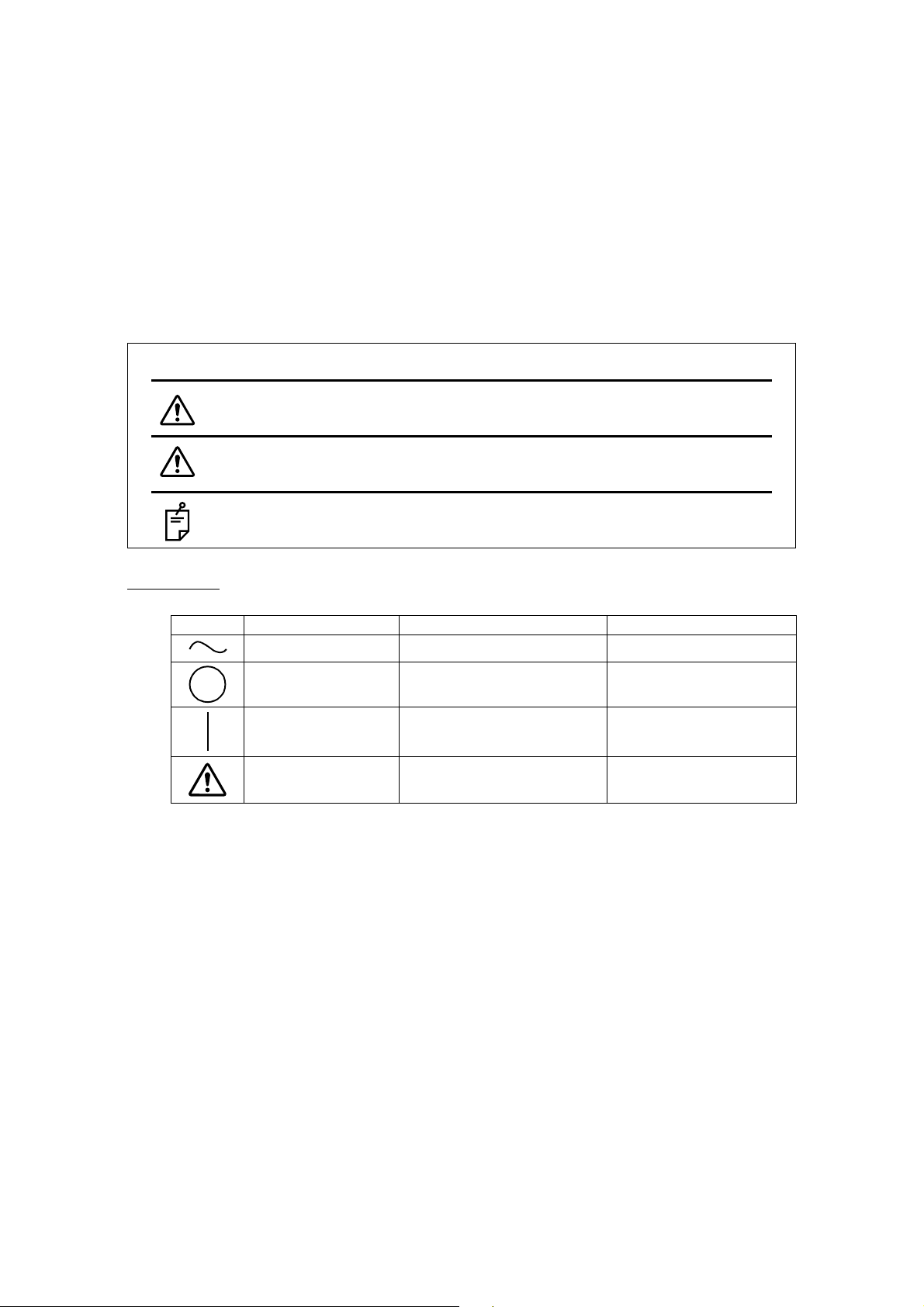
DISPLAYS AND SYMBOLS FOR SAFE USE
In order to encourage the safe use of this product, warnings labels are placed on the product and
written in the instruction manual.
We suggest that everyone understands the meaning of the following displays and icons before
reading the “GENERAL SAFETY INFORMATION” and text.
DISPLAYS
SYMBOLS
Display Meaning
Indicates a potentially hazardous situation which, if not
avoided, could result in death or serious injury.
Indicates a potentially hazardous situation which, if not
avoided, may result in minor or moderate injury.
Useful functions to know and attentions to prevent
troubles are noted.
Symbol IEC/ISO Publication Description Description (French)
IEC 60417-5032 Alternating Current Courant alternatif
IEC 60417-5008
Off (power: disconnection
from the main power supply)
Éteint (courant: coupure
avec le secteur)
IEC 60417-5007
On (power: connection to
the main power supply)
Allumé (courant: raccordement sur le secteur)
ISO 7010-W001 General warning sign
Symbole d'avertissement
général
WARNINGS
CAUTIONS
NOTES
Page 9
8
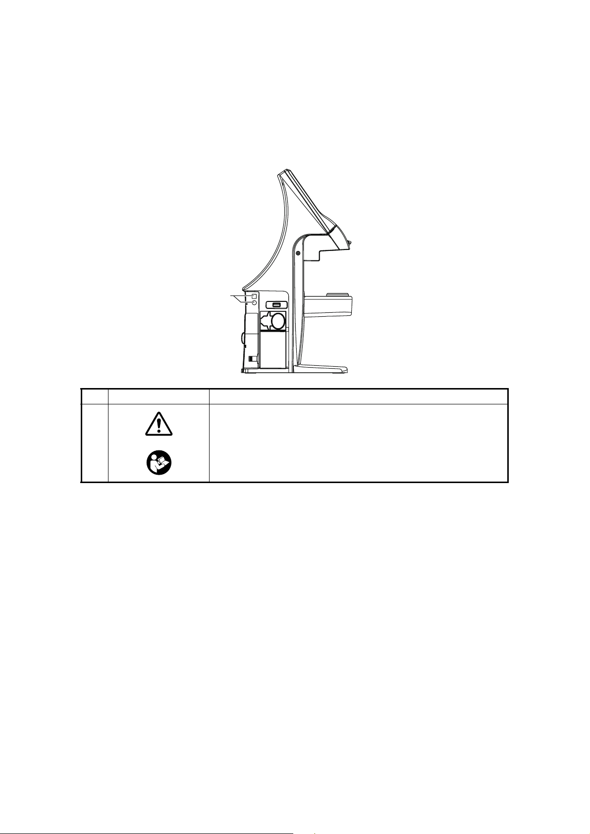
WARNING INDICATIONS AND POSITIONS
To insure safety, warning labels are provided.
Use the equipment correctly by following the warning instructions. If any of the following labels
are missing, please contact us at the address stated on the back cover.
No. Label Meaning
1
WARNING
To avoid injury caused by electric shock, do not open the cover.
Ask your dealer for service.
WARNING
To avoid injury, do not touch the AC adapter jack while using the
AC adapter.
1
Page 10

9
COMPONENTS
COMPONENTS
ACCESSORIES
The following are standard accessories. Make sure that all these items are included (quantity).
)1( dap noitcetorp sneL)1( elbac rewoP
)1( htolc nociliS) Model name: BPM040S09F021( retpada CA
)1( revoc tsuD)1( troppus snel tcatnoC
Printer paper (2)
(with printer specification)
User manual (1)
Instruction manual (1)
Guarantee sheet (1)
I
NSTRUCTION
MANUA
L
CO
M
PUTER
IZ
ED
LENS
METE
R
CL-300
Page 11
10
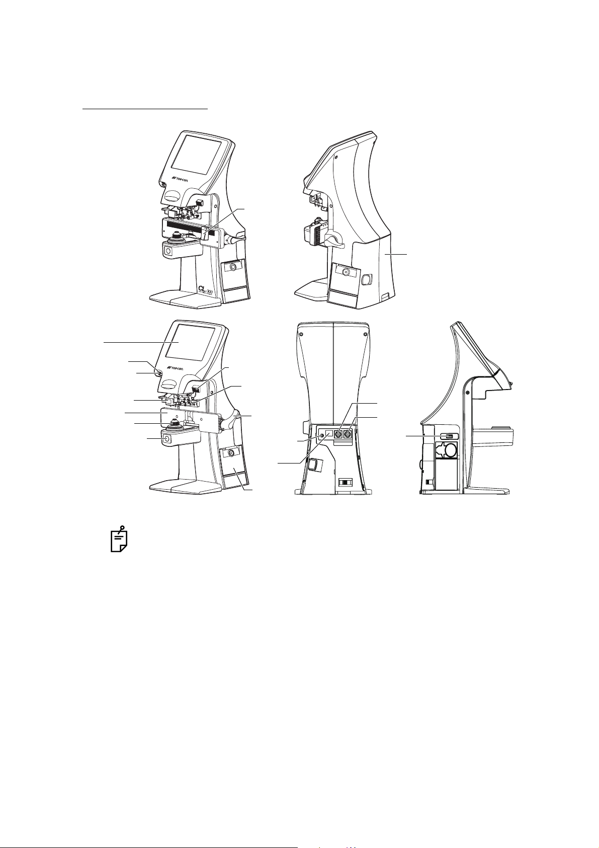
COMPONENTS
COMPONENT NAMES
• Use a LAN cable within 30m.
• The USB is for maintenance, not used normally.
• Power LED
Orange lamp ON: Power OFF
Green lamp ON: Power ON
Green lamp blinks: Under power save
• The model without PD and LAN function is not provided nose-pad and LAN.
IN OUT
Axis marker lever
LCD
Lens retainer
Lens table
Lens support
MEMORY button
Power switch
IN
OUT
RS-232C
Marking ink
cartridge
Lens table
lever
USB
AC adapter
jack
Power LED
Printer
cover
*LAN
*The model without LAN is also provided.
with PD Back side
Port cover
Nose reset
Page 12
11
COMPONENTS
COMPARTMENT SPACE
A space for keeping the contact lens holder, printer paper, etc. is secured in the back.
OPERATION METHOD OF CONTROL
The control panel is a touch panel. Do not use any sharp tools; e.g. ball point pen.
Tap To select any relevant item. Continue to press Used for long button press.
Touch the screen softly with a finger. Continue to touch the screen softly with a finger.
Page 13
12
COMPONENTS
CONTROL PANEL COMPONENTS
THE FUNCTION BUTTONS
The control panel is designed as a touch panel for performing various operations and settings.
It displays images and shows information, including set conditions and measurement results.
SINGLE MODE
R/L MODE
S button
Measurement mode
Settings button
R button
CLEAR button
PRINT button
UV buttonPrism button
+/- button
STEP button
R buttonL button
Page 14
13
COMPONENTS
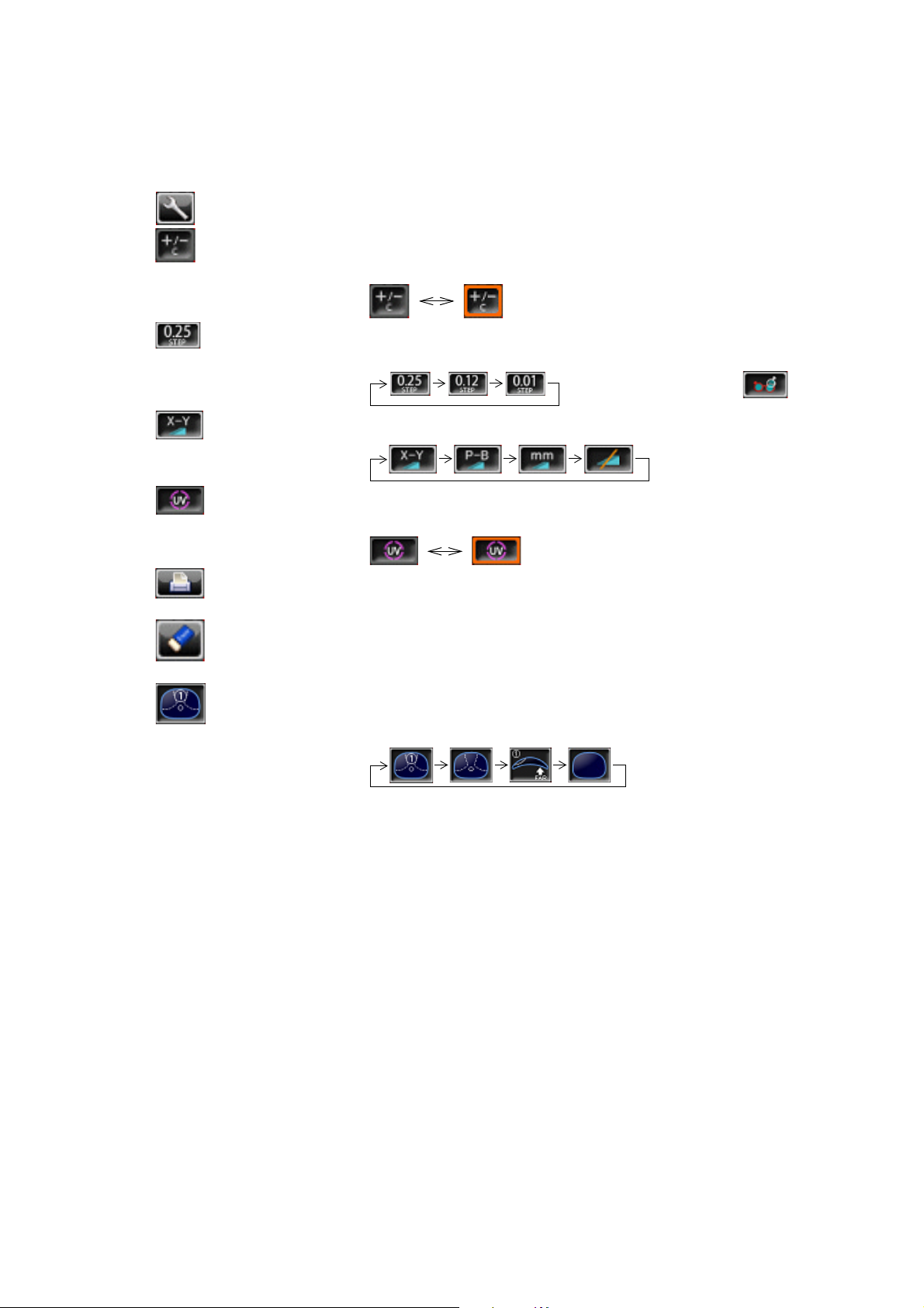
BUTTON NAMES
Settings button Displays the SETUP screen.
+/- button Used to change the degree (performed when an orange frame
is displayed).
STEP button Used to change the step of measurement value.
(Press it long time for A:step setting.)
Long button press:
Prism button Used to change the prism display.
UV button Used to change ON/OFF of UV measurement.
(performed when an orange frame is displayed).
PRINT button Press to obtain a print out readings.
Press to output data trough RS-232C.
CLEAR button Used to delete all data in memory.
To delete R and L separately, hold the button down.
Measurement mode button
Used to change the setting of measurement mode.
Page 15
14
COMPONENTS
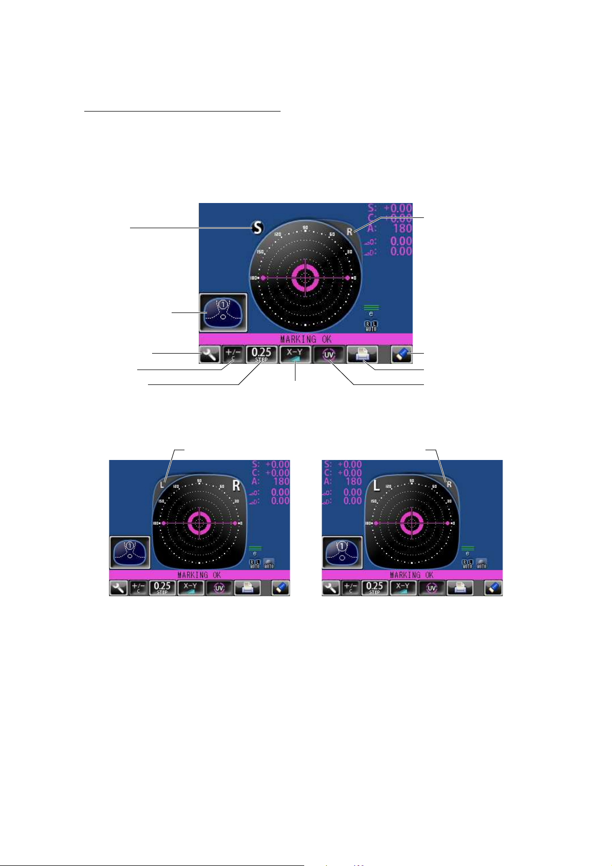
MEASUREMENT SCREEN
SINGLE MODE
R/L MODE
• When saved, S/R/L changes the color and stops.
• When the measurement value turns white, the measurement is finished.
• When the measurement value is yellow, the measurement of a multi-focal lens is being performed.
Lens measurement value
Target
Message bar
OFF CENTER
ERROR
ALIGNMENT OK
MARKING OK
Setup icon
Refer to
LIST OF SETUP ITEMS
Measurement value of
right-eye lens
Measurement value of
left-eye lens
Page 16
15
COMPONENTS
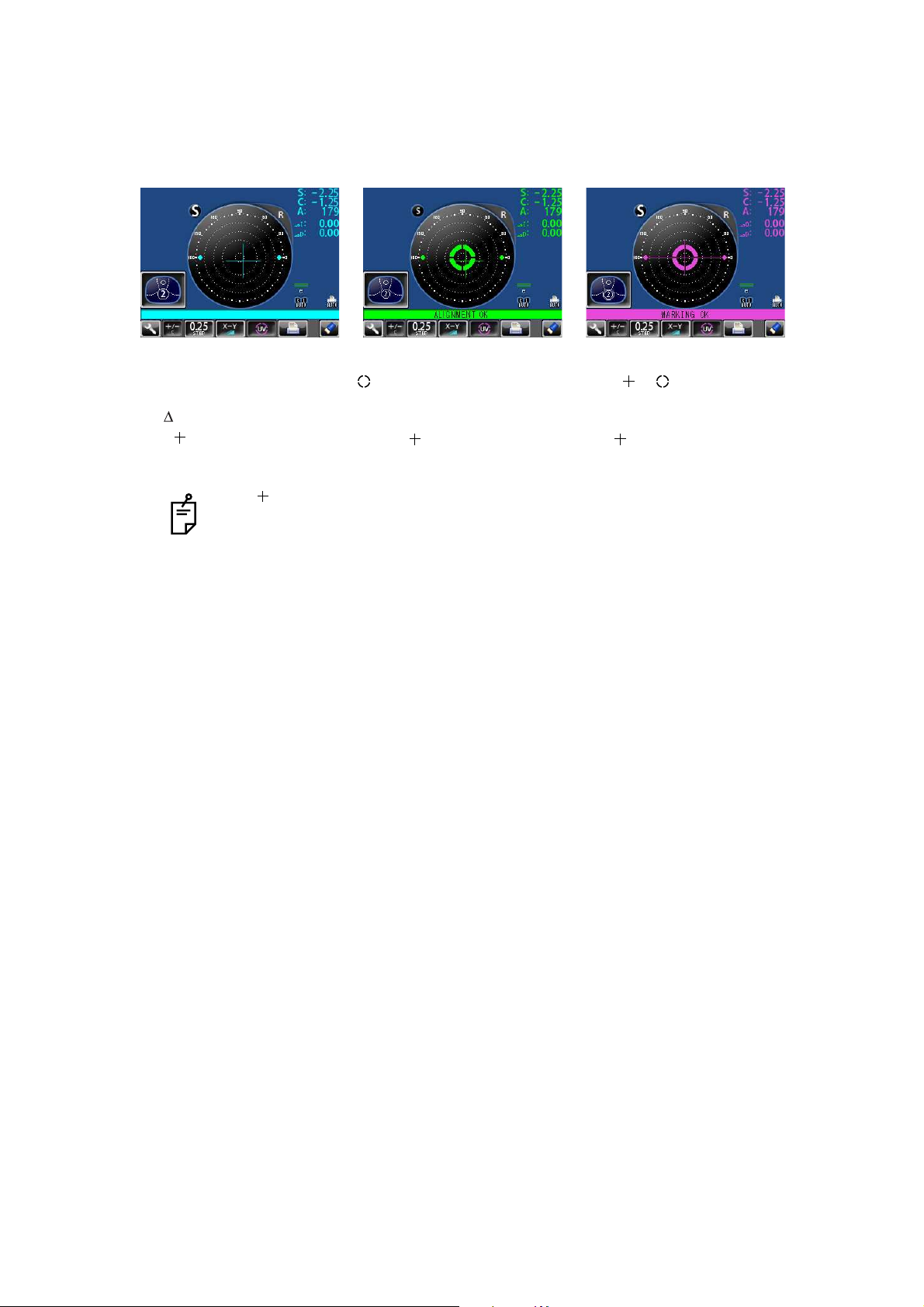
TARGET
Optical center's off.
[OFF CENTER] is displayed
when the optical center is off
by 4 or more.
Blue: , measurement value
[ALIGNMENT OK]
mark appears when the
lens is ready for measurement.
Green: , measurement value
[MARKING OK]
Place in mark, the lateral
line will extend, getting the
instrument ready for marking.
Pink: , measurement value
The target indicates optical center position.
And it varies depending on the symbol used in the spherical equivalent power.
Be noted that the target motion is different from that of Topcon telescopic lensmeters.
For axis marking procedures, don't use target's position but the prism value.
Refer the instruction in Page 27.
Page 17
16
COMPONENTS
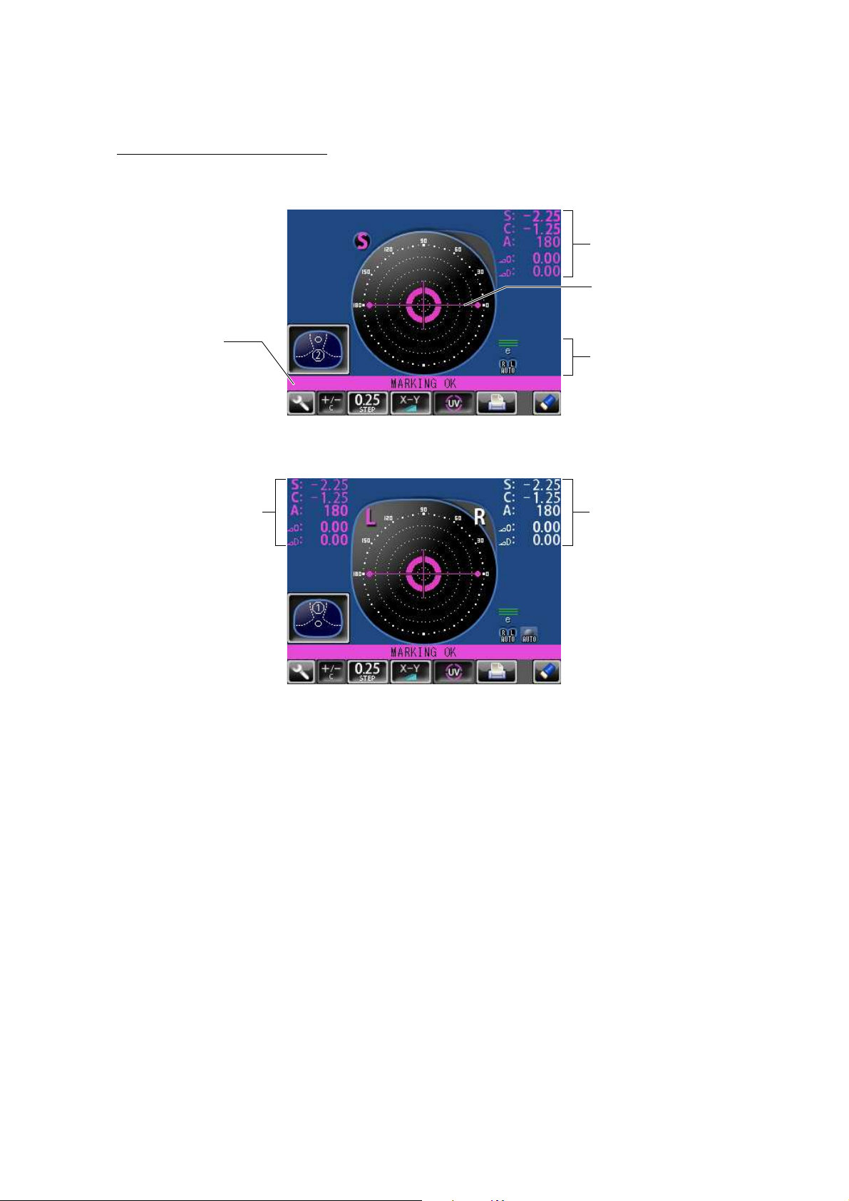
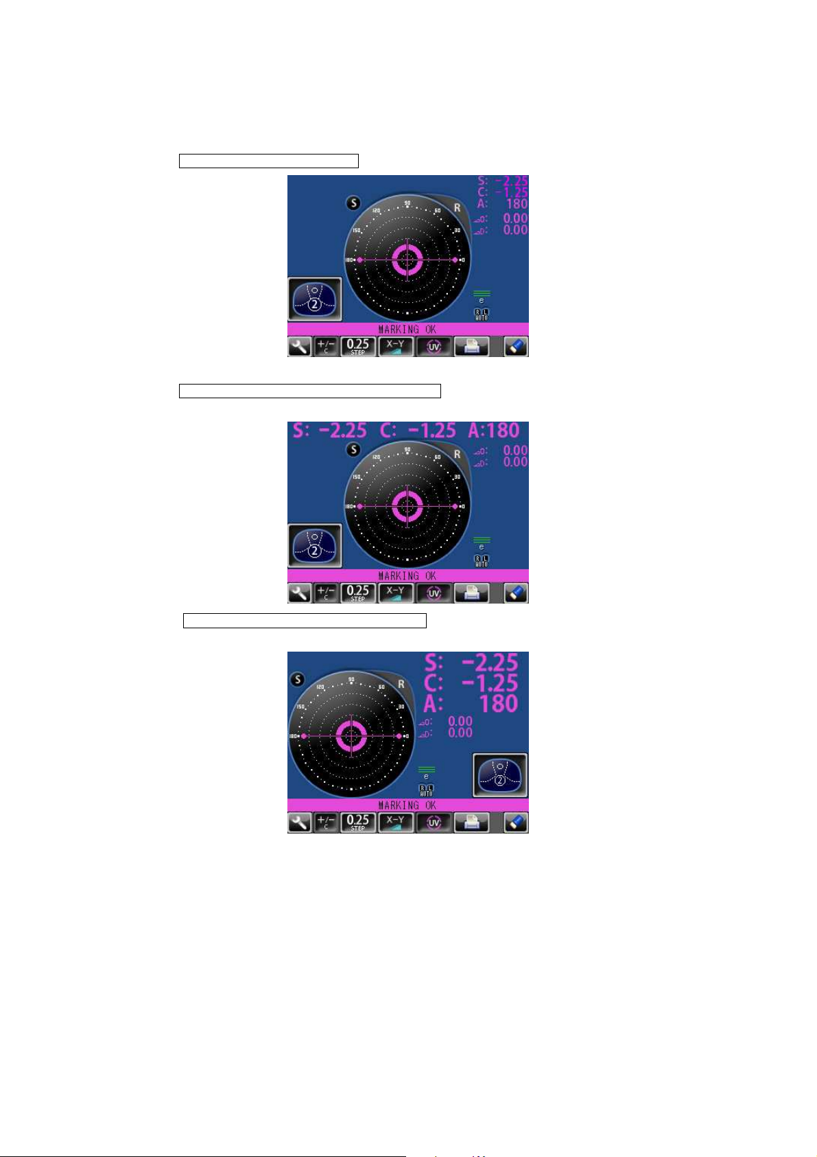
RESULT DISPLAY
When is selected, the display is normal.
When is selected, the SCA display is horizontally
enlarged.
When is selected, the SCA display is vertically
enlarged. The graphic moves to the opposite side.
INITIAL/DISPLAY/NORMAL
INITIAL/DISPLAY/HORIZONTAL LARGE
INITIAL/DISPLAY/VERTICAL LARGE
Page 18

17
COMPONENTS
SCREEN PRINT DISPLAY: (WHEN ENLARGED)
For framed lenses, of which both R and L are memorized, pressing the PRINT button enlarges
the SCA of both eyes. To return to the original state, tap the button.
SETUP SCREEN
The Setup screen is displayed by tapping the Settings button on Measurement screen.
• When the setting is , printing is performed automatically after saving the measurement value of both eyes.
• By tapping the button, the measurement screen is returned, leaving measurement values as saved.
• By tapping the button, the measurement screen is returned, clearing measurement values.
The button which is not allowed change.
PRINT/AUTO PRINT/ON
Page 19
18
PREPARATION
PREPARATION
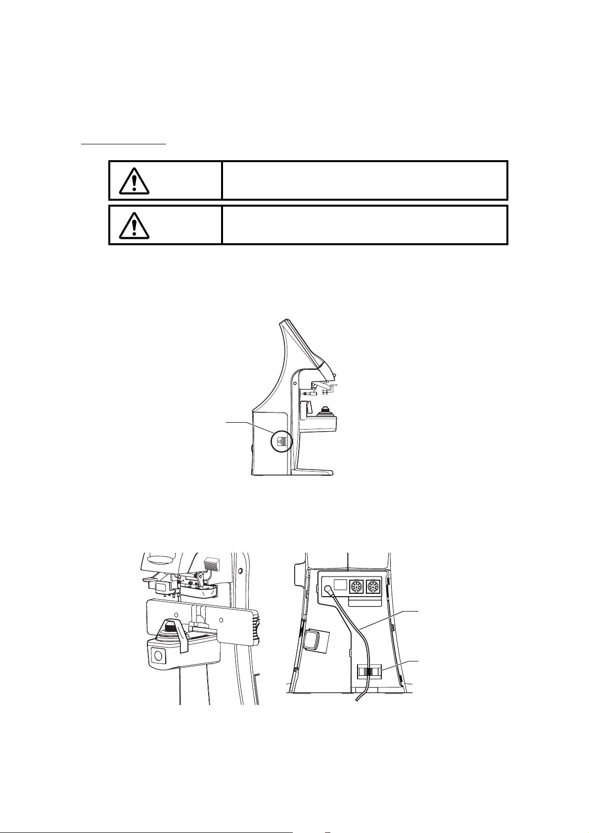
INSTALLATION
1 Remove the tape from the lens support.
2 Remove the tape from the marking ink cartridge.
3 Remove the port cover. Push the etched mark and move the cover to the arrow direction.
4 Plug in the power cable to the AC adapter.
5 Pass the cable through the cable clamp.
6 Connect the AC adapter plug to the AC adapter jack located on the rear panel of the main
body.
WARNING
To avoid fire/electric shocks, connect the power plug to a 3P
AC outlet (with ground) and secure grounding.
CAUTION
To avoid injury by falling, do not install the instrument on a
slope or in an unstable place.
Etched mark
IN OUT
AC adapter cable
Cable clamp
Page 20
19
PREPARATION
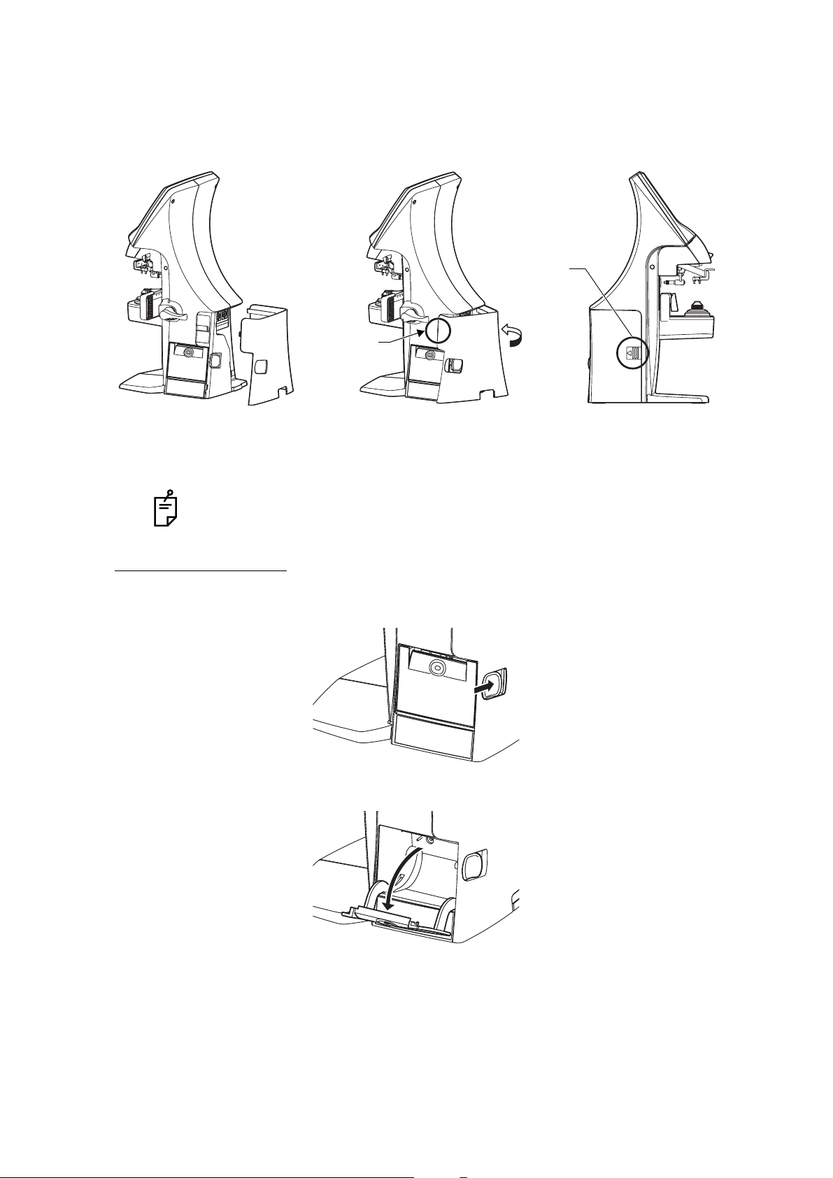
7 Setting the Port Cover.
SETTING THE PAPER
1 Press the PRINTER button and open the cover.
2 Open the printer cover to the limit.
By connecting an AC adapter, the main body starts automatically.
The stop to be
fitted first
Etched mark
Fit the stop of the figure above to the
main body. After fitting the stop, turn
the cover along the arrow direction.
Fit the stop by push
-
ing the etched mark
.
Page 21

20
PREPARATION
3 Insert the printer paper in the direction shown below and pull out the paper end to your
side by 7 to 8cm.
4 Bring the paper into the center, then close the printer cover.
AUTO POWER SAVE FUNCTION
1 When switch/tap operations are not done for about 10 minutes, or if no patient lens is set,
power save starts automatically.
2 During power save, the screen saver is actuated.
3 When the Memory button is pressed continuously for more than 2 seconds, the
backlight of the monitor goes off and the Power switch LED blink.
4 For reset, either tap the monitor, or press the Memory button, or press the Power switch
. Incidentally, press the Power switch short, or if pressed and held long, the
power is shut off
5 If auto power save function is not required, select .
6 To actuate power save manually, press the Memory button longer than 2 seconds.
• Printer feed function: Hold PRINTER button down.
• In case the printer cover is not firmly closed, printing will not start.
• A 58mm wide paper roll (example: TP-50KJ-R [Nippon Paper Co.]) is recommended.
Other paper rolls may cause abnormal printing noise or unclear print.
INITIAL/AUTO OFF/NO
Page 22
21
USING THE INSTRUMENT
USING THE INSTRUMENT
CHECKING BEFORE MEASURING
1 Check to see that there is no lens on the lens support.
2 Turn on the power switch.
3 Display will appear on the screen in a few seconds.
SETTING OF A LENS
A SINGLE LENS SETTING
1 Place the lens with the concave surface facing down on the lens support.
2 Lift and place down the lens retainer.
3 When holding a sharp-curve lens, provide your hand in case the lens falls.
A FRAMED LENS SETTING
1 Place the flamed lens on the lens support.
2 Turn the lens table lever and place the glass frame
against the lens table for measurement.
Alignment
Right and left....Place the frame against the lens
table, and move the frame right
and left finely.
Vertically ..........Move the table finely with the
lens table lever.
3 Lift and place down the lens retainer.
The ERROR screen will appear when there is a
lens left on the lens support or dust left on the
cover glass. Remove the lens or dust.
By tapping the screen, the error screen is cleared.
Page 23
22
USING THE INSTRUMENT
MEASURING A SINGLE FOCAL LENS
When a measurement mode button is , a single focal lens can be measured.
,
1 Move the lens and move the target near the center.
2 ALIGNMENT OK will be displayed when the target image center is within the minimum cir-
cle (0.5 or smaller).
3 The MARKING OK is displayed when the target image center is reached. If is dis-
played, "single focal lens" is memorized automatically.
When BEEP function is ON, the buzzer will sound.
(Note) The target may move in a contrary manner immediately after the lens is placed.
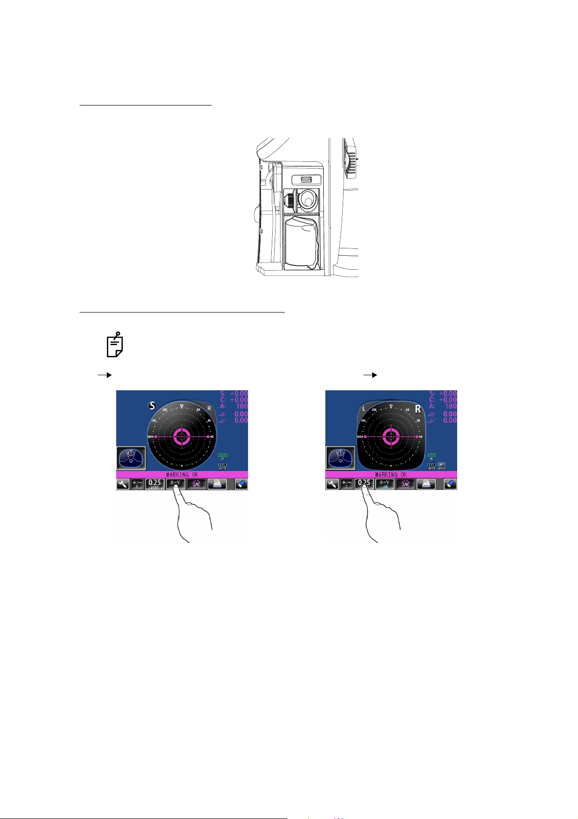
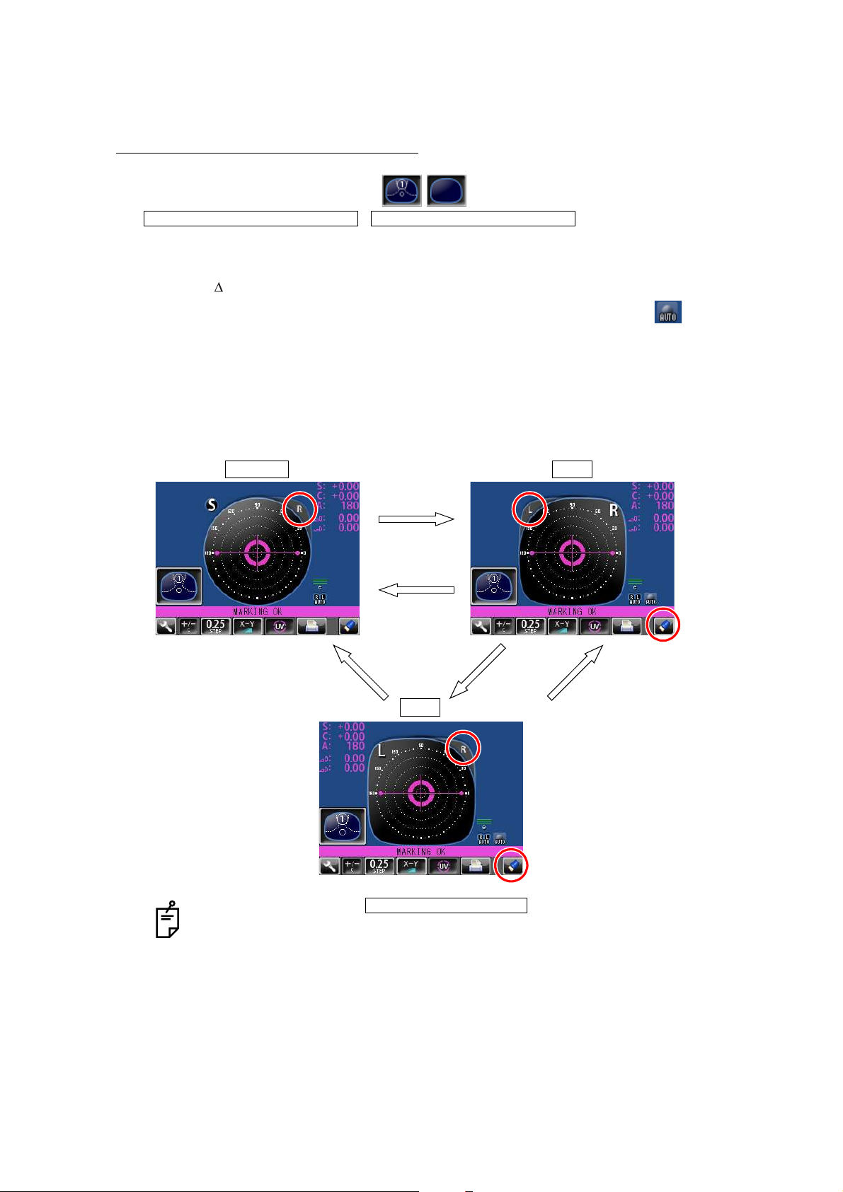
WHEN R/L DESIGNATION IS REQUIRED:
Tap the R button. The R/L display screen is displayed.
By tapping the L button, L is displayed. By tapping the CLEAR button, S is returned.
• When the setting is , the Single Lens screen is
returned by tapping the CLEAR button.
• By tapping the CLEAR button, saved measurement values are cleared.
INITIAL/PROGRESSIVE/AUTO INITIAL/PROGRESSIVE/OFF
Single lens R lens
L lens
R button
CLEAR button
L button R buttonCLEAR button
INITIAL/AUTO R/L/ R/L
Page 24
23
USING THE INSTRUMENT
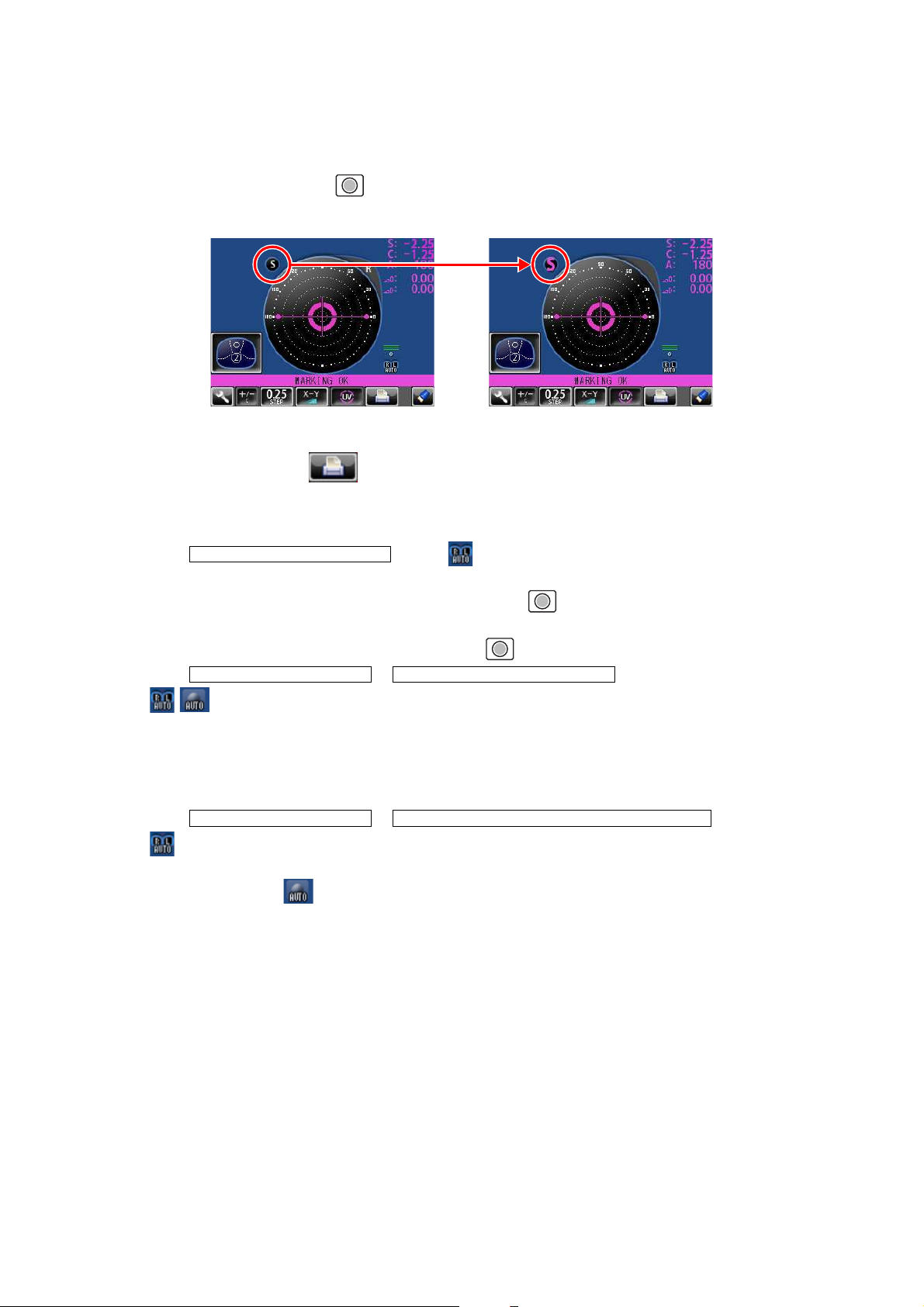
MANUAL SAVING:
Press the Memory button . The flicker-zooming “S” stops at the zoomed-up state and the
color is changed. (When R/L is displayed, R and L are changed.)
• When printing
Tap the PRINT button . When connecting with computer, data is transmitted.
MEASURING A FRAMED LENS
• When is set. ( is not displayed):
Tap the R button.
First align the right lens and press the Memory button .
Tap the L button.
Align the left lens and press the Memory button .
• When & is set.
( are displayed):
*Measurement of framed lens.
First, align the right lens to display “MARKING OK”. Then the result is automatically memorized, when the right lens is hold.
Removing the right lens will automatically move to the L measurement.
Align the left lens, then the result is automatically memorized, when the left lens is hold.
• When & is set.
( are displayed):
*Measurement of single lens/framed lens
Tap the R button. ( is displayed)
At first, align the right lens to display "MARKING OK". Then the result is automatically memorized, when the right lens is hold.
Removing the right lens will automatically move to the L measurement.
Align & hold the left lens. The result is automatically memorized.
INITIAL/AUTO R/L OFF
INITIAL/AUTO R/L / R/L INITIAL/AUTO MEMORY/ON
INITIAL/AUTO R/L/ R/L INITIAL/AUTO MEMORY/ S:OFF R/L:ON
Page 25
24
USING THE INSTRUMENT
MEASURING A PROGRESSIVE LENS
When a measurement mode button is or , a progressive lens can be measured.
When auto progressive recognition mode is on.
Discrimination of single focal lens and progressive focal lens can be done, which is not
easily possible from appearance.
When progressive only is set.
The auto progressive recognition measurement can be omitted. Start measurement from
step 3 below.
1 Measure the lower frame center
(position in the measurement mode button );
If the measurement is finished, Measurement mode button
changes to .
2 Measure the frame center
(position in the measurement mode button );
If the difference is over 0.50D or more, the screen changes.
3 Measure progressive lens for distance vision. (Excluding horizontal prism prescription
lenses) By moving the frame in all directions along the arrow mark displayed on the
screen, align with .
INITIAL/PROGRESSIVE/AUTO
INITIAL/PROGRESSIVE/PROGRESSIVE ONLY
The figure blinks and
the size changes.
The figure blinks and
the size changes.
1
2
Page 26

25
USING THE INSTRUMENT
4 When the distance vision measurement is obtained and saved, the screen automatically
changes to the near vision measurement display.
(The distance vision region can be easily detected, as you repeat moving and stopping
the lens little by little at measuring.)
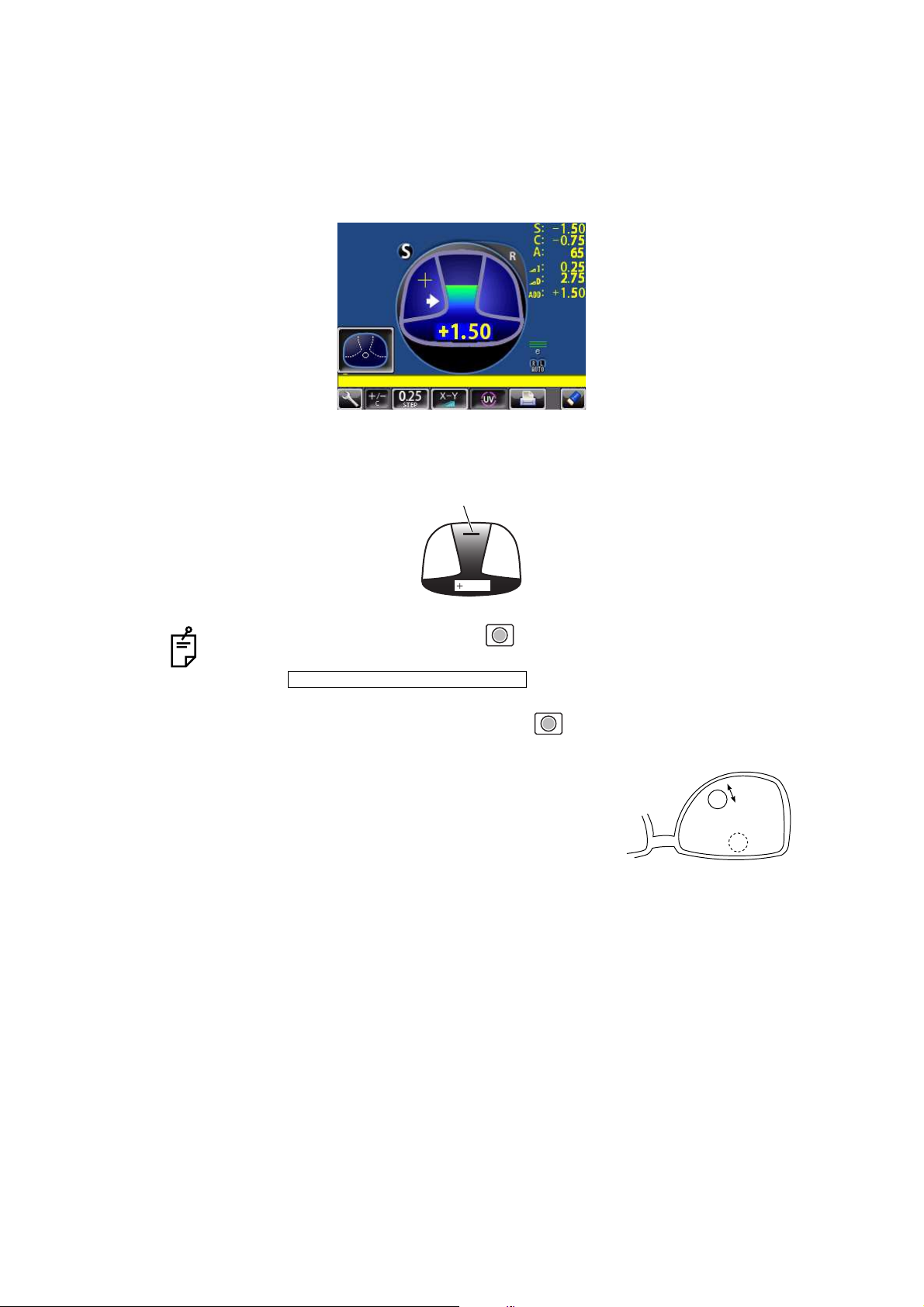
5 Measure progressive lens for near vision.
While watching the screen, draw out the lens table forward: the bar-meter extends and the
“+” appears. To bring this “+” to the bar-meter center, swing the lens right-left and extend
the bar-meter.
• By pressing the Memory button , you may manually store
the result of distance vision power measurement. The screen
will then switch to the near vision measurement.
When is selected as the
default setting, the result of the distance vision measurement is
not automatically stored. With this setting, you must press the
Memory button to save the distance vision.
• For high-power lenses, sometimes the distance vision region
cannot be easily detected. In this case, obtain the measurement in the approxi-
mate position that is shown on the above, and then press Memory button .
• For horizontal prism prescription lenses, press the MEMORY button at the
distance reference point.
INITIAL/FAR MEMORY/OFF
10mm approx.
10mm approx.
eye point
Page 27
26
USING THE INSTRUMENT
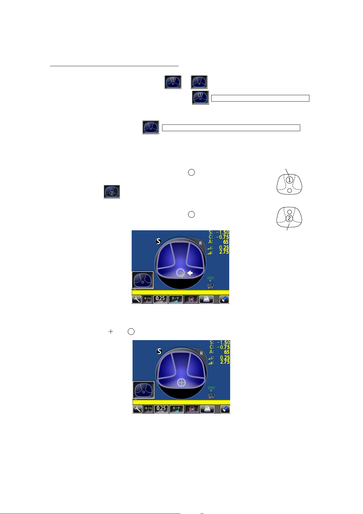
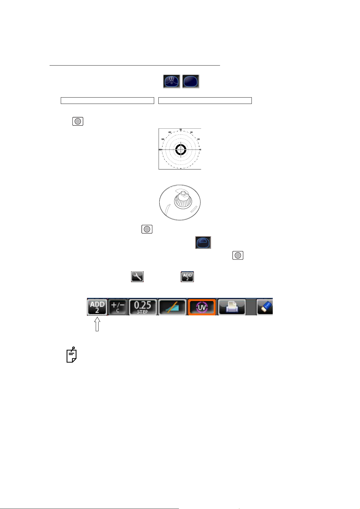
6 The condition illustrated below indicates that a position outside of the progressive zone is
being measured. Move the lens in the direction of the arrow to bring the "+" into the center
of the progressive zone.
7 The “+” becomes larger as it comes closer to the near vision position.
8 The ADD power is saved, the progressive lens measurement is completed.
• By pressing the MEMORY button , you may manually store the result of
near vision power measurement.
When is selected as the default setting, the
result of the near vision measurement is not automatically stored. With this setting, you must press the MEMORY button to save the near vision.
• When measuring a lens mounted in a large frame,
the ADD power may be higher because some lenses
increase the ADD power at a position below the near
vision region. Accordingly, if the lens is measured at
a point lower than the near vision eye point, the ADD
power reading may be higher. If you want to know
the accurate prescription, it is advisable to check the
measurement position at the hidden mark.
1.42
Knock-out black
INITIAL/NEAR MEMORY/OFF
Page 28

27
USING THE INSTRUMENT
#52*'4+%#.4#0)'241)4'55+8'4'%1)0+6+10
If a progressive lens is position so that the lens is outside of the progressive zone, the icon
of a screen bottom will change to . By tapping the button, the screen will auto-
matically switch to the distance vision measurement screen.
This appears when measuring the aspherical range of the progressive lens.
/'#574+0)#070241%'55'&241)4'55+8'.'05
As each unprocessed lens has a mark on the measuring point. Do measurement on the
mark position.
When the button is displayed, auto saving is not available.
• The measuring point for the distance or near vision region may be narrowed by
marks. Take care that the luminous flux may not be shaded during measurement.
ADD values will flicker when the luminous flux is shaded by marks or off the progressive zone at the time of measuring the near vision region.
An EX lens may not be provided with accurate meas
urements when measured
in the boundary.
• When the Setup screen appeared in the middle of measurement, measurement
values are cleared when the Measurement screen is returned.
distance vision region marked
Near vision region marked
Page 29
28
USING THE INSTRUMENT
MEASURING BI-FOCAL AND TRI-FOCAL LENSES
When a measurement mode button is , bi-focal and tri-focal lenses can be measured.
,
1 Align the distance vision in the center of the target image and press the MEMORY button
.
2 Move the lens into the near vision region (bi-focal segment).
3 Press the Memory button (Near Vision Measurement Start button in this case).
The measurement mode button is changed to .
4 Measure the bi-focal power and press the MEMORY button again.
To measure the 2nd near vision of tri-focal lenses, storing the 1st mid vision power auto-
matically changes the button to the button. Tap the button starts the near vision
measurement.
When the Setup screen appeared in the middle of measurement, measurement
values are cleared when the Measurement screen is returned.
INITIAL/PROGRESSIVE/AUTO INITIAL/PROGRESSIVE/OFF
ADD : +1.75
+2.50
Page 30
29
USING THE INSTRUMENT
MEASURING BI-FOCAL AND TRI-FOCAL LENSES (MEASURING THE
DIOPTER POWER OF LENSES WITH THE CONCAVE SIDE UP)
Measurement is possible when the measurement mode is .
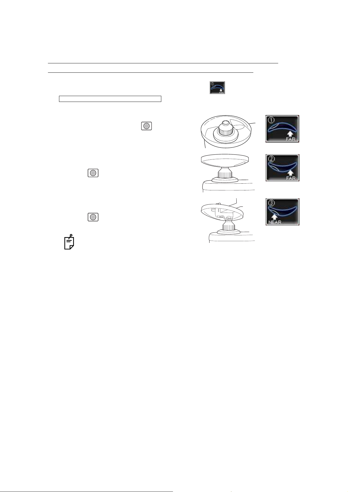
1 Set the lens with the concave side down as
usual, align the distance vision region, and
press the MEMORY button .
2 Set the lens with the concave side up, align the
distance vision region, and press the MEMORY
button .
3 Leaving the lens with the concave side up, align
the near vision region and press the MEMORY
button .
When the Setup screen appeared in the
middle of measurement, measurement
values are cleared when the Measurement screen is returned.
INITIAL/PROGRESSIVE/REVERSE
Lens position Screen
Page 31

30
USING THE INSTRUMENT
MEASURING A CONTACT LENS
MEASURING A HARD CONTACT LENS
1 Replace the lens support with the contact lens support.
2 Select . Setup icon will be displayed on the
screen.
3 Put the contact lens on contact lens support with special tweezer.
INITIAL/LENS/HARD CONTACT
Tweezer
Page 32

31
USING THE INSTRUMENT
MEASURING A SOFT CONTACT LENS WITHOUT ASTIGMATISM
1 Use the contact lens support for measuring as measuring a hard contact lens.
2 Select . Setup icon will be displayed on the
screen.
3 Pinch the soft contact lens with special tweezers to remove moisture from the lens. Put
the lens between paper and move three times to remove moisture from the surface.
4 If there is moisture dews on the surface when the contact lens is held to the light, put the
lens in the special solution again, and repeat the above. Moreover, take care about turning
inside out. When in the normal position, the lens looks like a bowl. However, when the
lens turns inside out, the rim looks warped. If the lens is ready for measurement, place it
on the contact lens holder and observe the shape (with tweezers) for alignment. After 30
seconds or more, the lens power changes since the internal moisture evaporates, therefore, measure it as quickly as possible.
A soft contact lens cannot be accurately measured because of its structure.
Although you can measure a soft contact lens power in following way, consider the
results an average and not the exact value.
If there is moisture on the soft contact lens surface, it is not possible to measure
because the luminous flux malfunctions.
Use the hard contact mode when measuring a toric soft contact lens.
When Contact Lens is selected, the measurement mode button is changed to
, and this cannot be changed.
INITIAL/LENS/SOFT CONTACT
Page 33

32
USING THE INSTRUMENT
A:STEP MODE
Select and hold STEP button down, change to the A:STEP
button.
The axial angle is rounded to 5°.
It is convenient for inputting the result by doing measurement with the trial lens left in the
temporary frame.
For release, press the button long.
Return to the STEP button , the 5° rounding is reset.
UV TRANSMISSION MEASUREMENT
UV Transmission Measurement is available when the UV button is orange-framed .
If not orange-framed, tap the UV button and make it orange-framed.
1 Move the lens and move the target near the center.
2 ALIGNMENT OK is displayed when the target image center is within the smallest circle
(within 0.5 ).
3 MARKING OK is displayed when the target image center is reached.
4 Press the Memory button .
5 The SCA value is saved, and the UV transmission measurement value is displayed in a
few seconds.
STEP of the measurement value is the state before changing to the temporary
frame (A:step).
After pressing the Memory button , do not move the lens until an UV transmission measurement value is displayed.
INITIAL/A:STEP/5
UV transmission
measurement value
Page 34

33
USING THE INSTRUMENT
CORRECTING THE UV TRANSMISSION
If UV transmission is not 100% after removing the lens, perform correction.
1 Confirm that no lens is put on the lens support.
2 Press and hold the UV button.
3 When correction is finished, the buzzer beeps.
During the UV transmission measurement/correction, do not look into the LED
irradiation part.
LED irradiation part
Page 35

34
USING THE INSTRUMENT
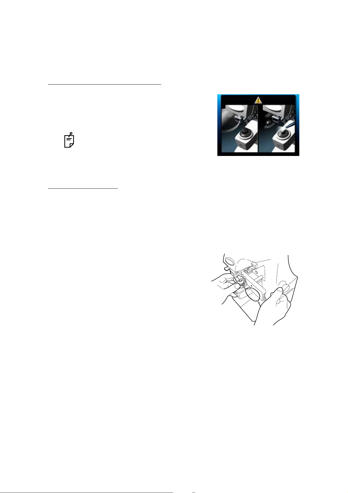
AXIS MARKING
(CARTRIDGE SPECIFICATION/STEEL NEEDLE SPECIFICATION)
Using the cartridge, one light touch to the lens can put a clear ink mark.
MARKING A LENS WITHOUT ASTIGMATISM
1 Move the lens until the centering mark coincides with the target image completely, and
MARKING OK will appear.
2 Depress the marking lever to mark the lens.
Centering mark
Line extends laterally to the target
Page 36

35
USING THE INSTRUMENT
MARKING A LENS WITH ASTIGMATISM
• Axis marking, maintaining the axis as prescribed
Align the target image with the center mark, approximating the axis angle mark to the angle as
prescribed. Finally, adjust by the numerical display of axis angle A:.
• Marking a cylindrical axis
Match the center mark with the target image, approximating the axis angle mark to 180
degrees.
Adjust A of the axis angle to 180 degrees.
Before performing alignment, set auto memory to off.
Confirm is not displayed at the setup icon.
Axis angle mark (every 5°)
Check here
Axis angle mark (every 5°)
Adjust to 180°.
Page 37

36
USING THE INSTRUMENT
MARKING A LENS WITH PRISM POWER
• When the prescription is displayed with X-Y (orthogonal
coordinates) ( )
Tap the prism button and get display.
Carry out aligning according to the prism value as
prescribed and as displayed on the screen.
I in prism value: Base In
O in prism value: Base Out
U in prism value: Base Up
D in prism value: Base Down
• When the prescription is displayed with P-B (polar coordinates) ( )
Tap the prism button and get display.
Carry out aligning according to the prism value as
prescribed and as displayed on the screen.
P: Prism value
B: Base orientation
• When the unit is mm ( )
Tap the prism button and get display.
The marks show the optical center
reaches the center of measurement by moving the
lens in the arrow directions by the distance as displayed.
: 3.0mm
: 2.0mm The position is shown in the right figure.
Take care that the polar coordinates are not the
same as the value on the angular scale in the
target image.
• 0 will be displayed if the spherical power S is around 0.
• When the prism value is more than 10 (vertical direction), the measurement
value is recognized as a reference value. For reference value, * (asterisk) is displayed at the measurement result. Measurement values recognized as reference value: SCA value, prism value, ADD value
INITIAL/PRISM/X-Y
INITIAL/PRISM/P-B
INITIAL/PRISM/mm
Page 38

37
USING THE INSTRUMENT
PRINTING ADDITIONAL TEXTBOX (WITH PRINTER SPECIFICATION)
On the print out with the measuring data, the user can input his own text, like office name,
address or special message. The available space is three line of 24 characters each.
Tap the .
Text enter screen will appear.
Tap the desired enter window, tap the button and input with keyboard.
Setting is completed by tapping the OK button.
PRINT/NAME/INPUT
Enter window
Printing the
additional textbox
Printout
Page 39

38
USING THE INSTRUMENT
SETTING A SEQUENCE NO.
Setting is carried out when writing a sequence No. on printing paper and transferring the
serial No., using RS-232C.
Tap the , and the screen as shown below will appear.
Enter numerals and fix by tapping the OK button.
No printing or counting is carried out in case of 0000.
Press MEMORY button , PRINT button and CLEAR button in this order,
and counting will be carried out. (except for single lens).
LENS PROTECTION PAD
The attached lens protection pad allows a soft contact with the measuring lens.
1 Fit the lens protection pad according to the instructions.
2 Select , and the measurement result will be automati-
cally compensated.
If the OK button is tapped without filling all 4 digits, the empty digit is saved as "0."
Example) OK
is saved.
INITIAL/SEQ.NO./INPUT
1 2
0 0 1 2
INITIAL/LENS/NORMAL(PAD)
Page 40

39
USING THE INSTRUMENT
MEASURING PD (PD FITTING) (WITH PD SPECIFICATION)
1 Select .
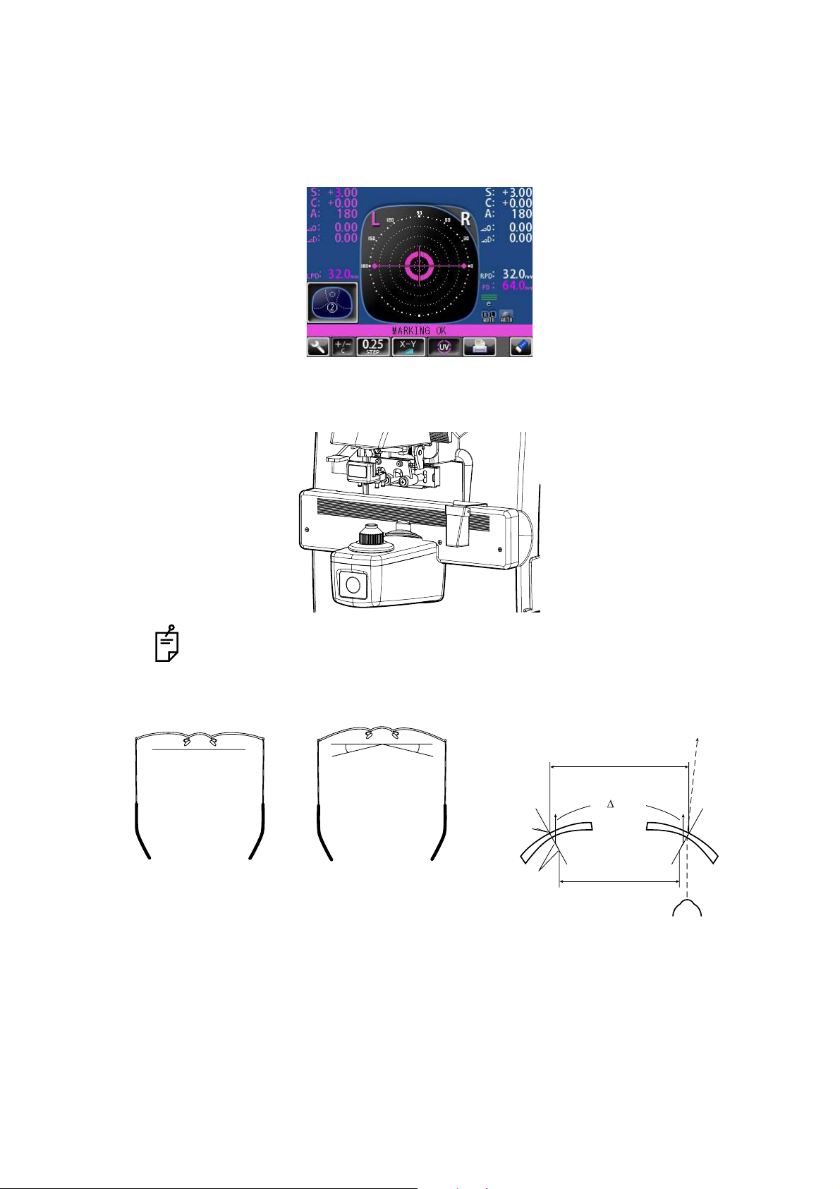
2 Put the spectacle frame onto the nose rest.
3 Align the lens until marking is OK. OK if the spectacle frame is horizontal along the lens
table line. If the spectacle frame has a camber, align it horizontally.
4 Press the lens retainer since the lens is in contact with the lens support sideways.
Let your hand go with the spectacle frame to prevent PD value shifting.
5 Press Memory button.
Errors will appear when the spectacle frame is not horizontally aligned.
INITIAL/PD/ON
Nose rest
Lens support
RPD
Page 41
40
USING THE INSTRUMENT
6 Follow the similar steps to measure the lens on the opposite side.
Totaled PD will be displayed.
7 Bring the nose rest to the extreme right and fold it. It will stick to the lens table by means of
a magnet.
Range 25~45mm on one side (minimum 0.5mm)
8 Difference may occur by the measurement technique and with low-power lenses having a
large camber angle.
If the measured PD value differs from that of marking PD.
No camber angle A camber angle
Since the optical center of the glasses mounted for
the infinite far is searched, the measured PD value
of CL-300 is called the PD/fitting value.
Marking
Principal point
PD fitting
(by PD mechanism)
Marking PD
0 flux
When the pupil is on the markin
g
position in the case of a concav
e
lens, a prism is added outside.
Page 42

41
USING THE INSTRUMENT
HOW TO OUTPUT DATA
OUTPUT USING RS232C
This instrument can output data to a PC, etc. via the RS232C interface.
1 Connect the RS232C cable to RS232C OUT.
2 Connect the other end of the cable to the PC., etc.
3 Confirm that set up of data communication settings.
For details, refer to “DATA COMMUNICATION (COMM.)” on page 47.
4 Perform measurements.
5 Tap the PRINT button of the control panel.
Data is outputted to the connected external device.
OUTPUT USING LAN
This instrument can output data to a PC, etc. via the LAN interface.
1 Connect the network cable to LAN OUT.
2 Connect the other end of the cable to the PC., etc.
3 Confirm that set up of LAN connection settings.
For details, refer to “LAN CONNECTION (LAN)” on page 48.
4 Perform measurements.
5 Tap the PRINT button of the control panel.
Data is outputted to the connected external device.
Page 43

42
SETTING FUNCTIONS ON SETUP SCREEN
SETTING FUNCTIONS ON SETUP SCREEN
OPERATING THE SETUP SCREEN
Various functions can be set on the SETUP screen.
PREPARATONS FOR SETTING
1 Make sure that the power cable is connected.
For connection, refer to “PREPARATION” on page 18.
2 Turn ON the POWER switch.
3 Tap the SETTINGS button on the control panel.
The SETUP screen is displayed.
SETTINGS button
Index
Return button
Back Page button Next Page button
Page display
Descriptions Current condition button
By tapping a current condition button,
the options buttons are displayed.
Page 44

43
SETTING FUNCTIONS ON SETUP SCREEN
OUTLINE OF SETUP SCREEN OPERATIONS
1 Tap and select the subject of setting.
2 Operate the or , as necessary, and display
the page to confirm/change.
3 Tap the Current condition button of the item to be changed and find the options button.
4 Tap the options button and change the setting.
INDEX
NEXT PAGE button BACK PAGE button
Options button
Page 45

44
SETTING FUNCTIONS ON SETUP SCREEN
• Instead of the options button, ten-key and keyboard would be displayed.
TEN-KEY:
Tap ten-key on the screen and enter the figure. If there are several windows to enter, tap the
window to enter the figure by ten-key. Setting is complete by tapping .
KEYBOARD:
Tap keyboard on the screen and enter characters. If there are several windows to enter, tap
the desired window, then enter the character by keyboard. Setting is complete by tapping
.
5 After entering all setting items, save the setting items and return to the Measurement
screen by tapping the Return button .
To return the setting to the previous status, turn off the power before tapping the
Return button .
OK
Enter window
OK
Enter window
Page 46

45
SETTING FUNCTIONS ON SETUP SCREEN
LIST OF SETUP ITEMS
Setup items are categorized into 5 large indexes.
"Initial"..................items related to the initial status after power on
"Print"...................items related to output from the internal printer
"Comm"................items related to data input/output with the external device
"LAN" ...................items related to output using the LAN
"Special"...............items related to maintenance (for service engineer only)
INITIAL (INITIAL SETTING)
Initial contains settings related to the initial status after power on.
Descriptions Options button Contents of setup Display of
Setup icon/
Display of button
Default
LENS NORMAL Measures a normal lens. NORMAL
NORMAL (PAD) Measures a normal lens wearing the
lens protection pad.
SOFT CONTACT Measures a soft contact lens.
HARD CONTACT Measures a hard contact lens.
DISPLAY HORIZONTAL LARGE Horizontally enlarges the SCA display. NORMAL
VERTICAL LARGE Vertically enlarges the SCA display.
NORMAL Normal display
PROGRESSIVE OFF Auto progressive recognition mode
OFF.
AUTO
AUTO Auto progressive recognition mode
ON.
PROGRESSIVE
ONLY
Always begins with the Progressive
zone center search mode of the progressive lens.
REVERSE Measures the diopter power with the
concave side up.
FAR MEMORY ON Auto memory of distance vision mea-
surement.
ON
OFF Manual memory of distance vision
measurement.
NEAR MEMORY ON Auto memory of near vision measure-
ment
ON
OFF Manual memory of near vision mea-
surement
Page 47

46
SETTING FUNCTIONS ON SETUP SCREEN
AUTO R/L R/L Measurement of framed lens:
Auto R/L switching
S/R/L
S/R/L Measurement of single lens/framed
lens: Auto R/L switching
OFF S/R/L switching
AUTO MEMORY ON Auto memory is ON when the lens
optical axis is aligned.
S : OFF
R/L : ON
S : OFF R/L : ON Auto memory OFF at measurement of
single lens. It is ON at measurement
of framed lens.
OFF Auto memory OFF.
UV ON UV measurement is ON OFF
OFF UV measurement is OFF
UV STEP 1% STEP UV measurement is ON: Step 1% 1% STEP
5% STEP UV measurement is ON: Step 5%
BEEP ON Buzzer sounds when a measured
value is stored or a button is pushed.
ON
OFF Buzzer OFF
STEP 0.25 0.25-step measurement. 0.25
0.12 0.12-step measurement.
0.01 0.01-step measurement.
A:STEP 5 Rounds axial angle settings to 5°
1
PRISM NO DISPLAY No prism display. X-Y
X-Y Rectangular coordinate display
P-B Polar coordinate display
mm mm display at PD/OFF
CYLINDER MIX Mixed display MIX
+ Plus-fixed display
- Minus-fixed display
Page 48

47
SETTING FUNCTIONS ON SETUP SCREEN
SETTING OF INTERNAL PRINTER (PRINT)
Print contains settings related to output from the internal printer.
DATA COMMUNICATION (COMM.)
Comm contains settings related to data input/output with the external device.
AUTO OFF YES Power save ON YES
NO Power save OFF
BRIGHTNESS LEVEL1 Level of LCD brightness
level 1(dark) level 6 (bright)
LEVEL6
LEVEL2
LEVEL3
LEVEL4
LEVEL5
LEVEL6
ABBE NORMAL 50-60 Abbe NORMAL
MID 40-50 Abbe
LOW 30-40 Abbe
PD ON PD value display ON
OFF No PD value display
SEQ.NO. INPUT Serial No. print mode
Descriptions Options button Contents of setup Display of
Setup icon/
Display of button
Default
PRINTER ON Printer output ON ON
OFF Printer output OFF
AUTO PRINT ON Auto memory output (S: When the
lens is removed)
R/L: When both lenses are the same
class (1st/2nd near vision of distance
vision)
ON
OFF Manual memory output
NAME SET Printing additional textbox
Descriptions Options button Contents of setup Display of
Setup icon/
Display of button
Default
RS-232C NEW FORMAT External output (NEW FORMAT) STD1
OLD FORMAT External output (OLD FORMAT)
STD1 External output (STD FORMAT)
Page 49

48
SETTING FUNCTIONS ON SETUP SCREEN
LAN CONNECTION (LAN)
LAN contains settings related to data input/output via LAN.
SPECIAL
SPECIAL is the mode for service engineer only; it can not be accessed.
Descriptions Options button Contents of setup Display of
Setup icon/
Display of button
Default
IP ADDRESS INPUT Set the IP address of CL-300.
Set the subnet mask of CL-300.
Set the default gateway of CL-300.
• When not used, set 0.0.0.0.
SETTING1 INPUT Set the IP address of the PC to output
data.
Set the shared name of the PC to output data.
SETTING2 INPUT Set the folder name of the PC to out-
put data.
• The holder name which can be set
up is in the directly under hierarchy
of a shared name.
Set the name of the user who makes
access to the PC to output data.
Set a password to make access to the
PC to output data.
For models without LAN function, LAN connection is not possible.
Page 50

49
MAINTENANCE
MAINTENANCE
REPLACING THE MARKING INK CARTRIDGE
(THE SAME APPLIES TO STEEL NEEDLE SPECIFICATION)
1 To replace the marking ink cartridge, remove the top screw. Pull out the cartridge while
applying pressure to it so as the spring not jump out from the inside.
Work the lens holder/stopper under the lowered condition.
2 To set the cartridge, insert the spring and keep the cartridge top well above the marking
ink holder, and then fasten the screw.
When not in use, put the dust cover over the cartridge (to prevent insect damage).
Steel needle
(optional accessory)
Screw
Marking ink holder
Spring
Marking ink
cartridge
Page 51

50
MAINTENANCE
SUPPLY OF INK FOR THE OPTIONAL STEEL NEEDLE
1 Replenish ink when poor marking happens.
2 Slide laterally and pull out the inkpot.
3 Slide off cover from the inkpot.
4 Infiltrate supply ink into the sponge well.
CLEANING COVER GLASSES
If the glass is dirty as indicated by arrows, it will affect
measurement accuracy adversely. If this occurs, clean
them with the attached silicon cloth.
Remove the lens support before cleaning the cover glass.
If the mark illustrated right appears at the lower part on
the screen, it means that the cover glass is dirty.
Carry out the following operation;
1 Wipe off the cover glass for cleaning.
2 Press CLEAR and TRANS buttons simultaneously and the instrument will restart. If the
measurement screen appears, continue the operation.
CLEANING THE INSTRUMENT
1 Wipe cover with damp cloth at regular interval. Never use cleanser or other chemicals.
Page 52

51
BEFORE REQUESTING SERVICE
BEFORE REQUESTING SERVICE
CAUTION MESSAGES
CHECK ITEMS
CLEAN THE COVER GLASS Carry out cleaning of the cover glass.
DIOPTER OVER
PRISM OVER
ERROR
Check to see that the lens is in the measurable scope.
Check to see that the lens is free from any flaw, dust or oil.
Clean both glasses and turn power on again.
PAPER END Printer paper is out. Load new paper.
CLOSE PRINTER COVER Close printer cover.
UV CALIBRATION NG Is the lens left on lens support?
Remove the lens from the lens support, and perform calibra-
tion again.
PRINTER HEAD OVER HEAT It is possible that the temperature of a printer head is rising.
Please turn off the power, and switch on a power supply
again after waiting for a while.
PRINTER CUTTER ERROR Please check whether the printer cover has closed or
whether there is not any foreign object in a printer.
PRINTER THERMISTOR NG Call service engineer.
INITIAL ERROR
(ERROR CODE)
Call service engineer. The error code of four digits is dis-
played.
The instrument does not get
ready for operation even if the
power switch is turned on.
Re-plug the power cord.
Operation of a button is not
effective.
Power supply cannot be turned
off even if you push the power
switch.
Press and hold the power switch for 10 seconds or more.
Then, the power supply turns off.
S, C values are wrong. Is the lens place with power on?
Remove the lens and turn on power again.
Is the measuring beam blocked by, dust, marks, grease, etc.
in the measured lens?
Marking is poor. Replace the marking ink cartridge. For a lens with sharp sur-
face curve, use the optional steel needle marking set.
The screen went out all of a
sudden.
The auto shut-off function is on.
Tap the control power, and the instrument will resume.
Pushed the PRINT button but
the printer does not work.
Is printer paper set properly?
Not inside out?
Page 53

52
SPECIFICATIONS
SPECIFICATIONS
SPECIFICATIONS
WITH PRINTER SPECIFICATION
Printer : Thermal printer, paper width 58mm, Printing additional textbox, AUTO PRINT
OPTIONAL ACCESSORIES
Steel needle marking set (steel needle x3, supply ink, inkpot, holder)
ORDERING CONSUMABLE SUPPLIES AND SPARES
When ordering consumable supplies, please tell the Product name, Part code number, necessary quantity and this Machine type.
Measurable scope
S: 0~ 25D, C: 0~ 10D, ADD: 0~+10D (0.01/0.12/0.25)
P: 0~13 (horizontal) 0~18 (vertical) (0.01/0.12/0.25),
A: 1~180° (1°)
Cylinder mode MIX/-/+
Prism mode No display / X-Y (Rectangular coordinates) /
P-B (polar coordinates) / mm
Contac
t lens Contact lenses are measurable.
Progressive focal lens Single focal/progressive lens recognition, distance vision detection,
ADD power bar-meter display
Display screen Color LCD 320x240 dots 5.7 Type
S, C, A, P, ADD, ADD R/L display, Enlarged SCA display.
Frame Auto R/L function
Menu screen Easy-to-watch screen with icon display
Lens diameter
5-100mm
Power supply 100-240V~ 50-60Hz 1.2A (Auto shut-off in 10 minutes)
Dimensions, weight 197 (W)x220 (D)x404 (H) 3.8kg approx.
* Subject to changes in design and/or specifications, without advanced notice.
Product name Part code No. Remark
Consumables Marking ink cartridge
(3 cartridges/set, white)
42028 4020 Standard accessory
Lens protection pad 42036 5500 Standard accessory
yrossecca dradnatS1004 00844repap retnirP
Steel needle marking set 42039 4010 Optional accessory
yrossecca lanoitpO1004 93024kni ylppuS
Marking ink cartridge
(3 cartridges/set, red)
42039 4030 Optional acces
sory
Page 54

53
GENERAL INFORMATION ON USAGE AND
GENERAL INFORMATION ON USAGE AND
MAINTENANCE
ENVIRONMENTAL CONDITIONS FOR USE
Indoor use Altitude up to 2,000m
Pollution degree II Temperature range: 5-40°C
Maximum relative humidity 80% for temperatures up to 31°C decreasing linearly to 50% relative humidity at 40°C
STORAGE, USAGE PERIOD AND OTHERS
1. Environmental conditions for use
Indoor use Altitude up to 2,000m
Pollution degree II Temperature range: 5-40°C
Maximum relative humidity 80% for temperatures up to 31°C decreasing linearly 50% relative humidity at 40°C
2. When storing the instrument, ensure that the following conditions are met:
(1) The instrument should not be splashed with water.
(2) Store the instrument where air pressure, temperature, moisture, ventilation, sunlight,
dust, salt/sulfurous air, etc. do not give any negative side effect.
(3) Do not store or transport the instrument on a slope or uneven surface or in an area
where it is subject to vibrations or instability.
(4) Do not store the instrument where chemicals are stored or gas is generated.
3. Usage period
8 years from delivery providing regular maintenance is performed (according to the self-certification [TOPCON data]).
SAFETY DESIGNATIONS PER IEC 60601-1 STANDARD
• Type of protection against electric shocks: Class I equipment
Class I equipment does not depend on basic insulation only for protection against electric
shocks. It can also be earthed; therefore, the metal parts with which one comes into contact
do not become conductive if the basic insulation fails.
• Degree of protection against harmful ingress of water: IPx0
CL-300 has no protection against ingress of water. (The degree of protection against harmful
ingress of water defined in IEC 60529 is IPx0)
• Classification according to the method(s) of sterilization or disinfection recommended by the
manufacturer: not applicable.
• Classification according to the degree of safety of application in the presence of a flammable
anaesthetic mixture with air or with oxygen or nitrous oxide: Equipment not suitable for use in
the presence of a flammable anaesthetic mixture with air or with oxygen or nitrous oxide. CL300 should be used in environments where no flammable anesthetics and/or flammable gases
are presents.
• Classification according to the mode of operation: Continuos operation.
Continuos operation is the operation under normal load for an unlimited period, without the
specified limits of temperature being exceeded.
Page 55

54
GENERAL INFORMATION ON USAGE AND MAINTENANCE
MAINTENANCE AND CHECKS
1. Regularly maintain and check all equipment and parts.
2. When using the instrument after a prolonged period of inactivity, confirm normal and safe
operation beforehand.
3. Take care not mar the cover glass with fingerprints and dirt.
4. When this instrument is not in use, apply the dust cover to it.
5. When the cover glass gets dirty, clean it following the "CLEANING COVER GLASSES" of
the User Manual.
DISPOSAL
Dispose of the instrument according to local disposal and recycling laws.
INTENDED USER PROFILE
This lensmeter is an electric instrument and it must be used in accordance with its Instruction
Manual.
This symbol is applicable for EU member countries only.
To avoid potential negative consequences for the environment and possibly human
health, this instrument should be disposed of (i) for EU member countries - in
accordance with WEEE (Directive on Waste Electrical and Electronic Equipment),
or (ii) for all other countries, in accordance with local disposal and recycling laws.
Page 56

55
GENERAL INFORMATION ON USAGE AND
ELECTROMAGNETIC COMPATIBILITY
This product conforms to the EMC Standard (IEC 60601-1-2:2001).
a) MEDICAL ELECTRICAL EQUIPMENT needs special precautions regarding EMC and needs to
be installed and put into service according to the EMC information provided in the ACCOMPANYING DOCUMENTS.
b) Portable and mobile RF communications equipment can affect MEDICAL ELECTRICAL
EQUIPMENT.
c) The use of ACCESSORIES, transducers and cables other than those specified, with the
exception of transducers and cables sold by the manufacturer of the EQUIPMENT or SYSTEM
as replacement parts for internal components, may result in increased EMISSIONS or
decreased IMMUNITY of the EQUIPMENT or SYSTEM.
d) The EQUIPMENT or SYSTEM should not be used adjacent to or stacked with other equipment.
IF adjacent or stacked use is necessary, the EQUIPMENT or SYSTEM should be observed to
verify normal operation in the configuration in which it will be used.
e) The use of the ACCESSORY, transducer or cable with EQUIPMENT and SYSTEMS other than
those specified may result in increased EMISSION or decreased IMMUNITY of the EQUIPMENT or SYSTEM.
Item Article code Model No. Length (m)
RS-232C cross cable 418120002 - 4.9
LAN CABLE - - 5.1
Guidance and manufacturer's declaration - electromagnetic emissions
The CL-300 is intended for use in the electromagnetic environment specified below.
The customer or the user of the CL-300 should assure that it is used in such an environment.
Emissions test Compliance Electromagnetic environment - guidance
RF emissions
CISPR 11
Group 1 The CL-300 uses RF energy only for its internal
function. Therefore, its RF emissions are very low
and are not likely to cause any interference in
nearby electronic equipment.
RF emissions
CISPR 11
Class A The CL-300 is suitable for use in all establish-
ments other than domestic and those directly connected to the public low-voltage power supply
network that supplies buildings used for domestic
purposes.
Harmonic emissions
IEC61000-3-2
Class A
Voltage fluctuations/
flicker emissions
IEC61000-3-3
Complies
Page 57

56
GENERAL INFORMATION ON USAGE AND MAINTENANCE
Guidance and manufacturer's declaration - electromagnetic immunity
The CL-300 is intended for use in the electromagnetic environment specified below.
The customer or the user of the CL-300 should assure that it is used in such an environment.
Immunity test IEC 60601
test level
Compliance
level
Electromagnetic environment -
guidance
Electrostatic
discharge (ESD)
IEC 61000-4-2
±6 kV contact
±8 kV air
±6 kV contact
±8 kV air
Floors should be wood, concrete
or ceramic tile. If floors are covered with synthetic material, the
relative humidity should be at
least 30%.
Electrical fast
transient/burst
IEC 61000-4-4
±2 kV for power
supply lines
±1 kV for
input/output lines
±2 kV for power
supply lines
±1 kV for
input/output lines
Mains power quality should be
that of a typical commercial or
hospital environment.
Surge
IEC 61000-4-5
±1 kV
differential mode
±2 kV
common mode
±1 kV
differential mode
±2 kV
common mode
Mains power quality should be
that of a typical commercial or
hospital environment.
Voltage dips, short
interruptions and
Voltage variations
on power supply
input lines
IEC 61000-4-11
<5%
U
t
(>95% dip in Ut)
for 0.5 cycle
40%
U
t
(60% dip in Ut)
for 5 cycles
70%
U
t
(30% dip in Ut)
for 25 cycles
<5% U
t
(>95% dip in Ut)
for 5 sec.
<5% U
t
(>95% dip in Ut)
for 0.5 cycle
40%
U
t
(60% dip in Ut)
for 5 cycles
70%
U
t
(30% dip in Ut)
for 25 cycles
<5% U
t
(>95% dip in Ut)
for 5 sec.
Mains power quality should be
that of a typical commercial or
hospital environment. If the user
or the CL-300 requires continued
operation during power mains
interruptions, it is recommended
that the CL-300 be powered from
an uninterruptible power supply
or battery.
Power frequency
(50/60 Hz)
magnetic field
IEC 61000-4-8
3 A/m 3 A/m Power frequency magnetic fields
should be at levels characteristic
of a typical location in a typical
commercial or hospital environment.
NOTE
U
t
is the a.c. mains voltage prior to application of the test level.
Page 58

57
GENERAL INFORMATION ON USAGE AND
Guidance and manufacturer's declaration - electromagnetic immunity
The CL-300 is intended for use in the electromagnetic environment specified below.
The customer or the user of the CL-300 should assure that it is used in such an environment.
Immunity test IEC 60601
test level
Compliance
level
Electromagnetic environment-
guidance
Conducted RF
IEC 61000-4-6
Radiated RF
IEC 61000-4-3
3 Vrms
150kHz to 80MHz
3 V/m
80MHz to 2.5GHz
3 V
3 V/m
Portable and mobile RF communications equipment should be used no
closer to an y part of the CL-300,
including cables, than the recommended separation distance calculated from the equation applicable to
the frequency of the transmitter.
Recommended separation distance
80MHz to 800MHz
800MHz to 2.5GHz
where
P is th e ma xim um ou tpu t
power rating of the transmitter in watts
(W) according to the transmitter manufacturer and
d is the recommended
separation distance in meters (m).
Field strengths from fixed RF transmitters, as determined by an electro-
magnetic site survey,
a
should be less
than the compliance level in each frequency range.
b
Interference may occur in the vicinity
of equipment marked with the following symbol:
NOTE 1 At 80 MHz and 800 MHz, the higher frequency range applies.
NOTE 2 These guidelines may not apply in all situations. Electromagnetic propagation is
affected by absorption and reflection from structures, objects and people.
a
Field strengths from fixed transmitters, such as base stations for radio (cellular/cordless) telephones and
land mobile radios, amateur radio, AM and FM radio broadcast and TV broadcast cannot be predicted
theoretically with accuracy. To assess the electromagnetic environment due to fixed RF transmitters, an
electromagnetic site survey should be considered. If the measured field strength in the location in which
the CL-300 is used exceeds the applicable RF compliance level above, the CL-300 should be observed
to verify normal operation. If abnormal performance is observed, additional measures may be necessary,
such as reorienting or relocating the CL-300.
b
Over the frequency range 150 kHz to 80 MHz, field strengths should be less than 3 V/m.
d
1.2 P=
d
1.2 P=
d
2.3 P=
Page 59

58
GENERAL INFORMATION ON USAGE AND MAINTENANCE
Recommended separation distance between portable and mobile RF
communications equipment and the CL-300
The CL-300 is intended for use in an electromagnetic environment in which radiated RF disturbances are controlled. The customer or the user of the CL-300 can help prevent electromagnetic interference by maintaining a minimum distance between portable and mobile RF
communications equipment (transmitters) and the CL-300 as recommended below, according
to the maximum output power of the communications equipment.
Rated maximum
output power of
transmitter
W
Separation distance according to frequency of transmitter
m
150kHz to 80MHz 80MHz to 800MHz 800MHz to 2.5GHz
0.01 0.12 0.12 0.23
0.1 0.38 0.38 0.73
1 1.2 1.2 2.3
10 3.8 3.8 7.3
100 12 12 23
For transmitters rated at a maximum output power not listed above, the recommended separation distance
d in metres (m) can be estimated using the equation applicable to the frequency of
the transmitter, where P is the maximum output power rating of the transmitter in watts (W)
according to the transmitter manufacturer.
NOTE 1 At 80 MHz and 800 MHz, the separation distance for the higher frequency range
applies.
NOTE 2 These guidelines may not apply in all situations. Electromagnetic propagation is
affected by absorption and reflection from structures, objects and people.
d 1.2
P
= d 1.2
P
= d = 2.3 P
Page 60

59
GENERAL INFORMATION ON USAGE AND
SHAPE OF PLUG
Country Voltage/frequency Shape of plug
Mexico 110V/50Hz Type C&E
Argentina 220V/60Hz Type A
Peru 220V/60Hz Type A
Venezuela 110V/50Hz Type C&E
Bolivia & Paraguay 220V/60Hz Type A (Most common)
Type H (infrequently)
Chile 220V/60Hz Type A
Colombia 110V/50Hz Type C
Brazil 220V/60Hz
127V/60Hz
Type A
Type C
Ecuador 110V/50Hz Type C&E
USA 120V/60Hz Type A (Hospital Grade)
Canada 120V/60Hz Type A (Hospital Grade)
Page 61

60
USING THE INSTRUMENT AS A SYSTEM
USING THE INSTRUMENT AS A SYSTEM
This product can perform data transfer with other devices.
For connectable devices and conditions for connection, ask your dealer/service engineer.
ON - LINE SYSTEM
The data of computerized lensmeter can be transferred to the instruments through RS232C interface, and also measuring data of the instruments can be transferred to computerized visiontester.
CL CV Computer
Page 62

When calling please give us the following information about
your unit:
• Machine type: CL-300
• Manufacturing No. (Shown on the rating plate on the back
of the instrument)
• Period of Usage (Please give us the date of purchase).
• Description of Problem (as detailed as possible).
COMPUTERIZED LENSMETER CL-300
USER MANUAL
Version of 2012 (2012.02-100LW0)
Date of issue: 15, February, 2012
Published by TOPCON CORPORATION
75-1 Hasunuma-cho, Itabashi-ku, Tokyo, 174-8580 Japan.
j2012 TOPCON CORPORATION
ALL RIGHTS RESERVED
Page 63

CL-300
COMPUTERIZED LENSMETER
42028 90050
Printed in Japan 2012.02-100LW0
Page 64

2
1. No part of this manual may be copied or reprinted, in whole or in part, without
prior written permission.
2. The contents of this manual are subject to change without prior notice and without legal obligation.
3. The contents of this manual are correct to the best of our knowledge. Please
inform us of any ambiguous or erroneous descriptions, missing information, etc.
2012 TOPCON CORPORATION
ALL RIGHTS RESERVED
Page 65

3
CONTENT
INTRODUCTION ........................................................................................................1
GENERAL SAFETY INFORMATION.......................................................................... 5
HOW TO READ THIS MANUAL .................................................................................6
GENERAL MAINTENANCE INFORMATION .............................................................6
USER MAINTENANCE...............................................................................................6
DISCLAIMERS ........................................................................................................... 6
DISPLAYS AND SYMBOLS FOR SAFE USE............................................................7
SYMBOLS .................................................................................................................. 7
WARNING INDICATIONS AND POSITIONS .............................................................8
COMPONENTS
ACCESSORIES..........................................................................................................9
COMPONENT NAMES.............................................................................................10
COMPARTMENT SPACE.........................................................................................11
OPERATION METHOD OF CONTROL ...................................................................11
CONTROL PANEL COMPONENTS.........................................................................12
MEASUREMENT SCREEN ......................................................................................14
SETUP SCREEN......................................................................................................17
PREPARATION
INSTALLATION ........................................................................................................18
SETTING THE PAPER.............................................................................................19
AUTO POWER SAVE FUNCTION ...........................................................................20
USING THE INSTRUMENT
CHECKING BEFORE MEASURING ........................................................................21
SETTING OF A LENS ..............................................................................................21
MEASURING A SINGLE FOCAL LENS ...................................................................22
MEASURING A PROGRESSIVE LENS ...................................................................24
MEASURING BI-FOCAL AND TRI-FOCAL LENSES...............................................28
MEASURING BI-FOCAL AND TRI-FOCAL LENSES (MEASURING THE DIOPTER
POWER OF LENSES WITH THE CONCAVE SIDE UP) .........................................29
MEASURING A CONTACT LENS ............................................................................30
A:STEP MODE ......................................................................................................... 32
UV TRANSMISSION MEASUREMENT....................................................................32
AXIS MARKING
(CARTRIDGE SPECIFICATION/STEEL NEEDLE SPECIFICATION) .....................34
PRINTING ADDITIONAL TEXTBOX (WITH PRINTER SPECIFICATION) ..............37
SETTING A SEQUENCE NO. ..................................................................................38
LENS PROTECTION PAD .......................................................................................38
MEASURING PD (PD FITTING) (WITH PD SPECIFICATION)................................ 39
HOW TO OUTPUT DATA.........................................................................................41
Page 66

4
SETTING FUNCTIONS ON SETUP SCREEN
OPERATING THE SETUP SCREEN........................................................................42
LIST OF SETUP ITEMS ...........................................................................................45
MAINTENANCE ........................................................................................................49
BEFORE REQUESTING SERVICE
CAUTION MESSAGES ............................................................................................51
CHECK ITEMS .........................................................................................................51
SPECIFICATIONS
SPECIFICATIONS....................................................................................................52
WITH PRINTER SPECIFICATION ...........................................................................52
OPTIONAL ACCESSORIES.....................................................................................52
GENERAL INFORMATION ON USAGE AND MAINTENANCE
ENVIRONMENTAL CONDITIONS FOR USE ..........................................................53
STORAGE, USAGE PERIOD AND OTHERS ..........................................................53
SAFETY DESIGNATIONS PER IEC 60601-1 STANDARD .....................................53
MAINTENANCE AND CHECKS ............................................................................... 54
DISPOSAL................................................................................................................54
INTENDED USER PROFILE ....................................................................................54
ELECTROMAGNETIC COMPATIBILITY..................................................................55
SHAPE OF PLUG .....................................................................................................59
USING THE INSTRUMENT AS A SYSTEM
ON - LINE SYSTEM .................................................................................................60
Page 67

5
GENERAL SAFETY INFORMATION
Preventing Electric Shocks and Fire
To avoid fire and electric shocks, do not place a cup or vessel containing water/fluid on the
instrument.
To avoid electric shocks, do not insert objects through vent holes or gaps or force them
inside the machine body.
To avoid electric shocks, do not attempt disassembling, rebuilding or repairing. For repairs,
call your dealer.
To avoid fire/electric shocks, do not install the instrument in a place where it may get wet.
If there is a malfunction or if the instrument produces smoke, immediately turn OFF the
POWER switch and unplug the power cable. To a avoid a possible fire due to malfunction,
call your dealer and ask for repairs.
Ensuring the Safety of Patients and Operators
To avoid injury by falling, do not install the instrument on a slope or in an unstable place.
Preventing Electric Shocks and Fire
Do not open the cover. For repairs, contact your Topcon dealer.
[The instrument may injure someone by electric shock.]
Electromagnetic Compatibility (EMC)
This instrument has been tested (with 100-240V) and found to comply with IEC60601-1-2:
2001. This instrument radiates radio frequency energy within standard and may affect other
devices in vicinity. If you have found out by turning on/off the instrument that it affects other
devices, it is recommended to change the direction, keep a proper distance against other
devices or change the outlet. If you have a question, consult with the selling agent.
WARNINGS
CAUTIONS
Page 68

6
HOW TO READ THIS MANUAL
• Read the instructions on pages 5 to 8 before using the machine.
• If you would like an overview of the system, begin by reading "USING THE INSTRUMENT"(page 21).
• For setting various functions, see "SETTING FUNCTIONS ON SETUP SCREEN" on page
42.
GENERAL MAINTENANCE INFORMATION
USER MAINTENANCE
To maintain the safety and performance of the equipment, never attempt to repair or perform
maintenance. These tasks should be performed by an authorized service representative.
Maintenance tasks that can be performed by the user are as follows; for details, follow the
manual’s instructions.
CLEANING COVER GLASSES
For details, see page 50 of this manual.
DISCLAIMERS
• TOPCON shall not take any responsibility for damages due to fire, groundquake, actions by
third person, or the negligence and misuse by the user and used under unusual conditions.
• TOPCON shall not take any responsibility for damage derived from the inability to use this
equipment, such as a loss of business profit and suspension of business.
• TOPCON shall not take any responsibility for damage caused by operations other than
those described in this Instruction Manual.
Page 69

7
DISPLAYS AND SYMBOLS FOR SAFE USE
In order to encourage the safe use of this product, warnings labels are placed on the product and
written in the instruction manual.
We suggest that everyone understands the meaning of the following displays and icons before
reading the “GENERAL SAFETY INFORMATION” and text.
DISPLAYS
SYMBOLS
Display Meaning
Indicates a potentially hazardous situation which, if not
avoided, could result in death or serious injury.
Indicates a potentially hazardous situation which, if not
avoided, may result in minor or moderate injury.
Useful functions to know and attentions to prevent
troubles are noted.
Symbol IEC/ISO Publication Description Description (French)
IEC 60417-5032 Alternating Current Courant alternatif
IEC 60417-5008
Off (power: disconnection
from the main power supply)
Éteint (courant: coupure
avec le secteur)
IEC 60417-5007
On (power: connection to
the main power supply)
Allumé (courant: raccordement sur le secteur)
ISO 7010-W001 General warning sign
Symbole d'avertissement
général
WARNINGS
CAUTIONS
NOTES
Page 70

8
WARNING INDICATIONS AND POSITIONS
To insure safety, warning labels are provided.
Use the equipment correctly by following the warning instructions. If any of the following labels
are missing, please contact us at the address stated on the back cover.
No. Label Meaning
1
WARNING
To avoid injury caused by electric shock, do not open the cover.
Ask your dealer for service.
WARNING
To avoid injury, do not touch the AC adapter jack while using the
AC adapter.
1
Page 71

9
COMPONENTS
COMPONENTS
ACCESSORIES
The following are standard accessories. Make sure that all these items are included (quantity).
)1( dap noitcetorp sneL)1( elbac rewoP
)1( htolc nociliS) Model name: BPM040S09F021( retpada CA
)1( revoc tsuD)1( troppus snel tcatnoC
Printer paper (2)
(with printer specification)
User manual (1)
Instruction manual (1)
Guarantee sheet (1)
I
NSTRUCTION
MANUA
L
CO
M
PUTER
IZ
ED
LENS
METE
R
CL-300
Page 72

10
COMPONENTS
COMPONENT NAMES
• Use a LAN cable within 30m.
• The USB is for maintenance, not used normally.
• Power LED
Orange lamp ON: Power OFF
Green lamp ON: Power ON
Green lamp blinks: Under power save
• The model without PD and LAN function is not provided nose-pad and LAN.
IN OUT
Axis marker lever
LCD
Lens retainer
Lens table
Lens support
MEMORY button
Power switch
IN
OUT
RS-232C
Marking ink
cartridge
Lens table
lever
USB
AC adapter
jack
Power LED
Printer
cover
*LAN
*The model without LAN is also provided.
with PD Back side
Port cover
Nose reset
Page 73

11
COMPONENTS
COMPARTMENT SPACE
A space for keeping the contact lens holder, printer paper, etc. is secured in the back.
OPERATION METHOD OF CONTROL
The control panel is a touch panel. Do not use any sharp tools; e.g. ball point pen.
Tap To select any relevant item. Continue to press Used for long button press.
Touch the screen softly with a finger. Continue to touch the screen softly with a finger.
Page 74

12
COMPONENTS
CONTROL PANEL COMPONENTS
THE FUNCTION BUTTONS
The control panel is designed as a touch panel for performing various operations and settings.
It displays images and shows information, including set conditions and measurement results.
SINGLE MODE
R/L MODE
S button
Measurement mode
Settings button
R button
CLEAR button
PRINT button
UV buttonPrism button
+/- button
STEP button
R buttonL button
Page 75

13
COMPONENTS
BUTTON NAMES
Settings button Displays the SETUP screen.
+/- button Used to change the degree (performed when an orange frame
is displayed).
STEP button Used to change the step of measurement value.
(Press it long time for A:step setting.)
Long button press:
Prism button Used to change the prism display.
UV button Used to change ON/OFF of UV measurement.
(performed when an orange frame is displayed).
PRINT button Press to obtain a print out readings.
Press to output data trough RS-232C.
CLEAR button Used to delete all data in memory.
To delete R and L separately, hold the button down.
Measurement mode button
Used to change the setting of measurement mode.
Page 76

14
COMPONENTS
MEASUREMENT SCREEN
SINGLE MODE
R/L MODE
• When saved, S/R/L changes the color and stops.
• When the measurement value turns white, the measurement is finished.
• When the measurement value is yellow, the measurement of a multi-focal lens is being performed.
Lens measurement value
Target
Message bar
OFF CENTER
ERROR
ALIGNMENT OK
MARKING OK
Setup icon
Refer to
LIST OF SETUP ITEMS
Measurement value of
right-eye lens
Measurement value of
left-eye lens
Page 77

15
COMPONENTS
TARGET
Optical center's off.
[OFF CENTER] is displayed
when the optical center is off
by 4 or more.
Blue: , measurement value
[ALIGNMENT OK]
mark appears when the
lens is ready for measurement.
Green: , measurement value
[MARKING OK]
Place in mark, the lateral
line will extend, getting the
instrument ready for marking.
Pink: , measurement value
The target indicates optical center position.
And it varies depending on the symbol used in the spherical equivalent power.
Be noted that the target motion is different from that of Topcon telescopic lensmeters.
For axis marking procedures, don't use target's position but the prism value.
Refer the instruction in Page 27.
Page 78

16
COMPONENTS
RESULT DISPLAY
When is selected, the display is normal.
When is selected, the SCA display is horizontally
enlarged.
When is selected, the SCA display is vertically
enlarged. The graphic moves to the opposite side.
INITIAL/DISPLAY/NORMAL
INITIAL/DISPLAY/HORIZONTAL LARGE
INITIAL/DISPLAY/VERTICAL LARGE
Page 79

17
COMPONENTS
SCREEN PRINT DISPLAY: (WHEN ENLARGED)
For framed lenses, of which both R and L are memorized, pressing the PRINT button enlarges
the SCA of both eyes. To return to the original state, tap the button.
SETUP SCREEN
The Setup screen is displayed by tapping the Settings button on Measurement screen.
• When the setting is , printing is performed automatically after saving the measurement value of both eyes.
• By tapping the button, the measurement screen is returned, leaving measurement values as saved.
• By tapping the button, the measurement screen is returned, clearing measurement values.
The button which is not allowed change.
PRINT/AUTO PRINT/ON
Page 80

18
PREPARATION
PREPARATION
INSTALLATION
1 Remove the tape from the lens support.
2 Remove the tape from the marking ink cartridge.
3 Remove the port cover. Push the etched mark and move the cover to the arrow direction.
4 Plug in the power cable to the AC adapter.
5 Pass the cable through the cable clamp.
6 Connect the AC adapter plug to the AC adapter jack located on the rear panel of the main
body.
WARNING
To avoid fire/electric shocks, connect the power plug to a 3P
AC outlet (with ground) and secure grounding.
CAUTION
To avoid injury by falling, do not install the instrument on a
slope or in an unstable place.
Etched mark
IN OUT
AC adapter cable
Cable clamp
Page 81

19
PREPARATION
7 Setting the Port Cover.
SETTING THE PAPER
1 Press the PRINTER button and open the cover.
2 Open the printer cover to the limit.
By connecting an AC adapter, the main body starts automatically.
The stop to be
fitted first
Etched mark
Fit the stop of the figure above to the
main body. After fitting the stop, turn
the cover along the arrow direction.
Fit the stop by push
-
ing the etched mark
.
Page 82

20
PREPARATION
3 Insert the printer paper in the direction shown below and pull out the paper end to your
side by 7 to 8cm.
4 Bring the paper into the center, then close the printer cover.
AUTO POWER SAVE FUNCTION
1 When switch/tap operations are not done for about 10 minutes, or if no patient lens is set,
power save starts automatically.
2 During power save, the screen saver is actuated.
3 When the Memory button is pressed continuously for more than 2 seconds, the
backlight of the monitor goes off and the Power switch LED blink.
4 For reset, either tap the monitor, or press the Memory button, or press the Power switch
. Incidentally, press the Power switch short, or if pressed and held long, the
power is shut off
5 If auto power save function is not required, select .
6 To actuate power save manually, press the Memory button longer than 2 seconds.
• Printer feed function: Hold PRINTER button down.
• In case the printer cover is not firmly closed, printing will not start.
• A 58mm wide paper roll (example: TP-50KJ-R [Nippon Paper Co.]) is recommended.
Other paper rolls may cause abnormal printing noise or unclear print.
INITIAL/AUTO OFF/NO
Page 83

21
USING THE INSTRUMENT
USING THE INSTRUMENT
CHECKING BEFORE MEASURING
1 Check to see that there is no lens on the lens support.
2 Turn on the power switch.
3 Display will appear on the screen in a few seconds.
SETTING OF A LENS
A SINGLE LENS SETTING
1 Place the lens with the concave surface facing down on the lens support.
2 Lift and place down the lens retainer.
3 When holding a sharp-curve lens, provide your hand in case the lens falls.
A FRAMED LENS SETTING
1 Place the flamed lens on the lens support.
2 Turn the lens table lever and place the glass frame
against the lens table for measurement.
Alignment
Right and left....Place the frame against the lens
table, and move the frame right
and left finely.
Vertically ..........Move the table finely with the
lens table lever.
3 Lift and place down the lens retainer.
The ERROR screen will appear when there is a
lens left on the lens support or dust left on the
cover glass. Remove the lens or dust.
By tapping the screen, the error screen is cleared.
Page 84

22
USING THE INSTRUMENT
MEASURING A SINGLE FOCAL LENS
When a measurement mode button is , a single focal lens can be measured.
,
1 Move the lens and move the target near the center.
2 ALIGNMENT OK will be displayed when the target image center is within the minimum cir-
cle (0.5 or smaller).
3 The MARKING OK is displayed when the target image center is reached. If is dis-
played, "single focal lens" is memorized automatically.
When BEEP function is ON, the buzzer will sound.
(Note) The target may move in a contrary manner immediately after the lens is placed.
WHEN R/L DESIGNATION IS REQUIRED:
Tap the R button. The R/L display screen is displayed.
By tapping the L button, L is displayed. By tapping the CLEAR button, S is returned.
• When the setting is , the Single Lens screen is
returned by tapping the CLEAR button.
• By tapping the CLEAR button, saved measurement values are cleared.
INITIAL/PROGRESSIVE/AUTO INITIAL/PROGRESSIVE/OFF
Single lens R lens
L lens
R button
CLEAR button
L button R buttonCLEAR button
INITIAL/AUTO R/L/ R/L
Page 85

23
USING THE INSTRUMENT
MANUAL SAVING:
Press the Memory button . The flicker-zooming “S” stops at the zoomed-up state and the
color is changed. (When R/L is displayed, R and L are changed.)
• When printing
Tap the PRINT button . When connecting with computer, data is transmitted.
MEASURING A FRAMED LENS
• When is set. ( is not displayed):
Tap the R button.
First align the right lens and press the Memory button .
Tap the L button.
Align the left lens and press the Memory button .
• When & is set.
( are displayed):
*Measurement of framed lens.
First, align the right lens to display “MARKING OK”. Then the result is automatically memorized, when the right lens is hold.
Removing the right lens will automatically move to the L measurement.
Align the left lens, then the result is automatically memorized, when the left lens is hold.
• When & is set.
( are displayed):
*Measurement of single lens/framed lens
Tap the R button. ( is displayed)
At first, align the right lens to display "MARKING OK". Then the result is automatically memorized, when the right lens is hold.
Removing the right lens will automatically move to the L measurement.
Align & hold the left lens. The result is automatically memorized.
INITIAL/AUTO R/L OFF
INITIAL/AUTO R/L / R/L INITIAL/AUTO MEMORY/ON
INITIAL/AUTO R/L/ R/L INITIAL/AUTO MEMORY/ S:OFF R/L:ON
Page 86

24
USING THE INSTRUMENT
MEASURING A PROGRESSIVE LENS
When a measurement mode button is or , a progressive lens can be measured.
When auto progressive recognition mode is on.
Discrimination of single focal lens and progressive focal lens can be done, which is not
easily possible from appearance.
When progressive only is set.
The auto progressive recognition measurement can be omitted. Start measurement from
step 3 below.
1 Measure the lower frame center
(position in the measurement mode button );
If the measurement is finished, Measurement mode button
changes to .
2 Measure the frame center
(position in the measurement mode button );
If the difference is over 0.50D or more, the screen changes.
3 Measure progressive lens for distance vision. (Excluding horizontal prism prescription
lenses) By moving the frame in all directions along the arrow mark displayed on the
screen, align with .
INITIAL/PROGRESSIVE/AUTO
INITIAL/PROGRESSIVE/PROGRESSIVE ONLY
The figure blinks and
the size changes.
The figure blinks and
the size changes.
1
2
Page 87
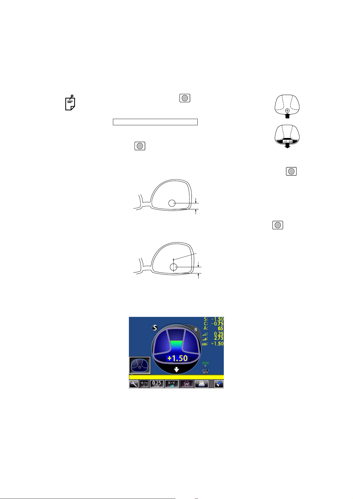
25
USING THE INSTRUMENT
4 When the distance vision measurement is obtained and saved, the screen automatically
changes to the near vision measurement display.
(The distance vision region can be easily detected, as you repeat moving and stopping
the lens little by little at measuring.)
5 Measure progressive lens for near vision.
While watching the screen, draw out the lens table forward: the bar-meter extends and the
“+” appears. To bring this “+” to the bar-meter center, swing the lens right-left and extend
the bar-meter.
• By pressing the Memory button , you may manually store
the result of distance vision power measurement. The screen
will then switch to the near vision measurement.
When is selected as the
default setting, the result of the distance vision measurement is
not automatically stored. With this setting, you must press the
Memory button to save the distance vision.
• For high-power lenses, sometimes the distance vision region
cannot be easily detected. In this case, obtain the measurement in the approxi-
mate position that is shown on the above, and then press Memory button .
• For horizontal prism prescription lenses, press the MEMORY button at the
distance reference point.
INITIAL/FAR MEMORY/OFF
10mm approx.
10mm approx.
eye point
Page 88

26
USING THE INSTRUMENT
6 The condition illustrated below indicates that a position outside of the progressive zone is
being measured. Move the lens in the direction of the arrow to bring the "+" into the center
of the progressive zone.
7 The “+” becomes larger as it comes closer to the near vision position.
8 The ADD power is saved, the progressive lens measurement is completed.
• By pressing the MEMORY button , you may manually store the result of
near vision power measurement.
When is selected as the default setting, the
result of the near vision measurement is not automatically stored. With this setting, you must press the MEMORY button to save the near vision.
• When measuring a lens mounted in a large frame,
the ADD power may be higher because some lenses
increase the ADD power at a position below the near
vision region. Accordingly, if the lens is measured at
a point lower than the near vision eye point, the ADD
power reading may be higher. If you want to know
the accurate prescription, it is advisable to check the
measurement position at the hidden mark.
1.42
Knock-out black
INITIAL/NEAR MEMORY/OFF
Page 89

27
USING THE INSTRUMENT
#52*'4+%#.4#0)'241)4'55+8'4'%1)0+6+10
If a progressive lens is position so that the lens is outside of the progressive zone, the icon
of a screen bottom will change to . By tapping the button, the screen will auto-
matically switch to the distance vision measurement screen.
This appears when measuring the aspherical range of the progressive lens.
/'#574+0)#070241%'55'&241)4'55+8'.'05
As each unprocessed lens has a mark on the measuring point. Do measurement on the
mark position.
When the button is displayed, auto saving is not available.
• The measuring point for the distance or near vision region may be narrowed by
marks. Take care that the luminous flux may not be shaded during measurement.
ADD values will flicker when the luminous flux is shaded by marks or off the progressive zone at the time of measuring the near vision region.
An EX lens may not be provided with accurate meas
urements when measured
in the boundary.
• When the Setup screen appeared in the middle of measurement, measurement
values are cleared when the Measurement screen is returned.
distance vision region marked
Near vision region marked
Page 90

28
USING THE INSTRUMENT
MEASURING BI-FOCAL AND TRI-FOCAL LENSES
When a measurement mode button is , bi-focal and tri-focal lenses can be measured.
,
1 Align the distance vision in the center of the target image and press the MEMORY button
.
2 Move the lens into the near vision region (bi-focal segment).
3 Press the Memory button (Near Vision Measurement Start button in this case).
The measurement mode button is changed to .
4 Measure the bi-focal power and press the MEMORY button again.
To measure the 2nd near vision of tri-focal lenses, storing the 1st mid vision power auto-
matically changes the button to the button. Tap the button starts the near vision
measurement.
When the Setup screen appeared in the middle of measurement, measurement
values are cleared when the Measurement screen is returned.
INITIAL/PROGRESSIVE/AUTO INITIAL/PROGRESSIVE/OFF
ADD : +1.75
+2.50
Page 91

29
USING THE INSTRUMENT
MEASURING BI-FOCAL AND TRI-FOCAL LENSES (MEASURING THE
DIOPTER POWER OF LENSES WITH THE CONCAVE SIDE UP)
Measurement is possible when the measurement mode is .
1 Set the lens with the concave side down as
usual, align the distance vision region, and
press the MEMORY button .
2 Set the lens with the concave side up, align the
distance vision region, and press the MEMORY
button .
3 Leaving the lens with the concave side up, align
the near vision region and press the MEMORY
button .
When the Setup screen appeared in the
middle of measurement, measurement
values are cleared when the Measurement screen is returned.
INITIAL/PROGRESSIVE/REVERSE
Lens position Screen
Page 92

30
USING THE INSTRUMENT
MEASURING A CONTACT LENS
MEASURING A HARD CONTACT LENS
1 Replace the lens support with the contact lens support.
2 Select . Setup icon will be displayed on the
screen.
3 Put the contact lens on contact lens support with special tweezer.
INITIAL/LENS/HARD CONTACT
Tweezer
Page 93

31
USING THE INSTRUMENT
MEASURING A SOFT CONTACT LENS WITHOUT ASTIGMATISM
1 Use the contact lens support for measuring as measuring a hard contact lens.
2 Select . Setup icon will be displayed on the
screen.
3 Pinch the soft contact lens with special tweezers to remove moisture from the lens. Put
the lens between paper and move three times to remove moisture from the surface.
4 If there is moisture dews on the surface when the contact lens is held to the light, put the
lens in the special solution again, and repeat the above. Moreover, take care about turning
inside out. When in the normal position, the lens looks like a bowl. However, when the
lens turns inside out, the rim looks warped. If the lens is ready for measurement, place it
on the contact lens holder and observe the shape (with tweezers) for alignment. After 30
seconds or more, the lens power changes since the internal moisture evaporates, therefore, measure it as quickly as possible.
A soft contact lens cannot be accurately measured because of its structure.
Although you can measure a soft contact lens power in following way, consider the
results an average and not the exact value.
If there is moisture on the soft contact lens surface, it is not possible to measure
because the luminous flux malfunctions.
Use the hard contact mode when measuring a toric soft contact lens.
When Contact Lens is selected, the measurement mode button is changed to
, and this cannot be changed.
INITIAL/LENS/SOFT CONTACT
Page 94

32
USING THE INSTRUMENT
A:STEP MODE
Select and hold STEP button down, change to the A:STEP
button.
The axial angle is rounded to 5°.
It is convenient for inputting the result by doing measurement with the trial lens left in the
temporary frame.
For release, press the button long.
Return to the STEP button , the 5° rounding is reset.
UV TRANSMISSION MEASUREMENT
UV Transmission Measurement is available when the UV button is orange-framed .
If not orange-framed, tap the UV button and make it orange-framed.
1 Move the lens and move the target near the center.
2 ALIGNMENT OK is displayed when the target image center is within the smallest circle
(within 0.5 ).
3 MARKING OK is displayed when the target image center is reached.
4 Press the Memory button .
5 The SCA value is saved, and the UV transmission measurement value is displayed in a
few seconds.
STEP of the measurement value is the state before changing to the temporary
frame (A:step).
After pressing the Memory button , do not move the lens until an UV transmission measurement value is displayed.
INITIAL/A:STEP/5
UV transmission
measurement value
Page 95

33
USING THE INSTRUMENT
CORRECTING THE UV TRANSMISSION
If UV transmission is not 100% after removing the lens, perform correction.
1 Confirm that no lens is put on the lens support.
2 Press and hold the UV button.
3 When correction is finished, the buzzer beeps.
During the UV transmission measurement/correction, do not look into the LED
irradiation part.
LED irradiation part
Page 96

34
USING THE INSTRUMENT
AXIS MARKING
(CARTRIDGE SPECIFICATION/STEEL NEEDLE SPECIFICATION)
Using the cartridge, one light touch to the lens can put a clear ink mark.
MARKING A LENS WITHOUT ASTIGMATISM
1 Move the lens until the centering mark coincides with the target image completely, and
MARKING OK will appear.
2 Depress the marking lever to mark the lens.
Centering mark
Line extends laterally to the target
Page 97

35
USING THE INSTRUMENT
MARKING A LENS WITH ASTIGMATISM
• Axis marking, maintaining the axis as prescribed
Align the target image with the center mark, approximating the axis angle mark to the angle as
prescribed. Finally, adjust by the numerical display of axis angle A:.
• Marking a cylindrical axis
Match the center mark with the target image, approximating the axis angle mark to 180
degrees.
Adjust A of the axis angle to 180 degrees.
Before performing alignment, set auto memory to off.
Confirm is not displayed at the setup icon.
Axis angle mark (every 5°)
Check here
Axis angle mark (every 5°)
Adjust to 180°.
Page 98

36
USING THE INSTRUMENT
MARKING A LENS WITH PRISM POWER
• When the prescription is displayed with X-Y (orthogonal
coordinates) ( )
Tap the prism button and get display.
Carry out aligning according to the prism value as
prescribed and as displayed on the screen.
I in prism value: Base In
O in prism value: Base Out
U in prism value: Base Up
D in prism value: Base Down
• When the prescription is displayed with P-B (polar coordinates) ( )
Tap the prism button and get display.
Carry out aligning according to the prism value as
prescribed and as displayed on the screen.
P: Prism value
B: Base orientation
• When the unit is mm ( )
Tap the prism button and get display.
The marks show the optical center
reaches the center of measurement by moving the
lens in the arrow directions by the distance as displayed.
: 3.0mm
: 2.0mm The position is shown in the right figure.
Take care that the polar coordinates are not the
same as the value on the angular scale in the
target image.
• 0 will be displayed if the spherical power S is around 0.
• When the prism value is more than 10 (vertical direction), the measurement
value is recognized as a reference value. For reference value, * (asterisk) is displayed at the measurement result. Measurement values recognized as reference value: SCA value, prism value, ADD value
INITIAL/PRISM/X-Y
INITIAL/PRISM/P-B
INITIAL/PRISM/mm
Page 99

37
USING THE INSTRUMENT
PRINTING ADDITIONAL TEXTBOX (WITH PRINTER SPECIFICATION)
On the print out with the measuring data, the user can input his own text, like office name,
address or special message. The available space is three line of 24 characters each.
Tap the .
Text enter screen will appear.
Tap the desired enter window, tap the button and input with keyboard.
Setting is completed by tapping the OK button.
PRINT/NAME/INPUT
Enter window
Printing the
additional textbox
Printout
Page 100

38
USING THE INSTRUMENT
SETTING A SEQUENCE NO.
Setting is carried out when writing a sequence No. on printing paper and transferring the
serial No., using RS-232C.
Tap the , and the screen as shown below will appear.
Enter numerals and fix by tapping the OK button.
No printing or counting is carried out in case of 0000.
Press MEMORY button , PRINT button and CLEAR button in this order,
and counting will be carried out. (except for single lens).
LENS PROTECTION PAD
The attached lens protection pad allows a soft contact with the measuring lens.
1 Fit the lens protection pad according to the instructions.
2 Select , and the measurement result will be automati-
cally compensated.
If the OK button is tapped without filling all 4 digits, the empty digit is saved as "0."
Example) OK
is saved.
INITIAL/SEQ.NO./INPUT
1 2
0 0 1 2
INITIAL/LENS/NORMAL(PAD)
 Loading...