

Page 1
INSTRUCTION
MANUAL
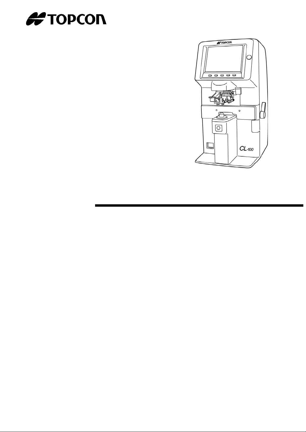
COMPUTERIZED LENSMETER
CL
-
100
Page 2

INTRODUCTION
Thank you for purchasing the TOPCON
Computerized Lensmeter CL-100.
This Instruction Manual covers an overview of the TOPCON
Computerized Lensmeter CL-100’s basic operations,
troubleshooting, maintenance and cleaning.
To get the best usage from the instrument, please read the “Safety indications”
and “Safety precautions”.
Keep this Manual within reach for future reference.
Precautions
• This is a precision instrument. It is expected that the instrument is used
under normal room temperature and humidity condition.
• Install the instrument on a level, stabilized desk. Do not exposed to direct
sunlight.
• Instrument must be kept clean at all times. Turn off and cover the instrument
when it is not in use.
• For accurate measurements, make sure there is no dust or oil on the lens to
be tested or on any portion in which the lens comes into contact with.
• Topcon is not responsible for any unauthorized disassembling and
remodeling of the instrument.
• If the equipment is used in a manner other than that specified by the
manufacturer, the warranty provided for the equipment may be impaired.
1
Page 3
DISPLAY FOR SAFE USE
In order to encourage the safe use of this product, important warnings are put on the product and
written in the instruction manual.
We suggest that everyone understands the meaning of the following displays and icons before
reading the “Safety Cautions” and text.
DISPLAY
CAUTION
• Personal
injury refers to hurt, burn, electric shock, etc.
• Property damage refers to extensive damage to building or equipment and furniture.
Ignoring this display may lead to personal
injury or property damage.
MEANING
ICONS MEANING
This icon indicates a Hazard Warning.
Specific content is expressed with words or an icon either
inserted in the icon itself or located close to the icon
SAFETY CAUTIONS
CAUTION
Icons Prevention item Page
To prevent electrical shock, turn off the power switch and
disconnect power cord before replacing fuses.
Replace fuses with the same rating and type.
2
23
Page 4
USAGE AND MAINTENANCE
Usage:
The lensmeter is an electric equipment and the usage must be based on the
Instruction Manual.
USER MAINTENANCE:
To maintain the safety and performance of the equipment, never attempt to do the
maintenance of parts specified herein, which should be taken care of by our servicemen.
The maintenance items that can be covered by users are the following; for details, follow
the instructions.
Operating the fuse:
The fuse is replaceable.
For details, see page 23 of this manual.
ESCAPE CLAUSE
• TOPCON shall not take any responsibility for damages due to fire, earthquake,
actions by third person, or the negligence and missuse by the user and used under
unusual conditions.
• TOPCON shall not take any responsibility for damage derived from the inability to
use this equipment, such as a loss of business profit and suspension of business.
• TOPCON shall not take any responsibility for damage caused by operations other
than those described in this Instruction Manual.
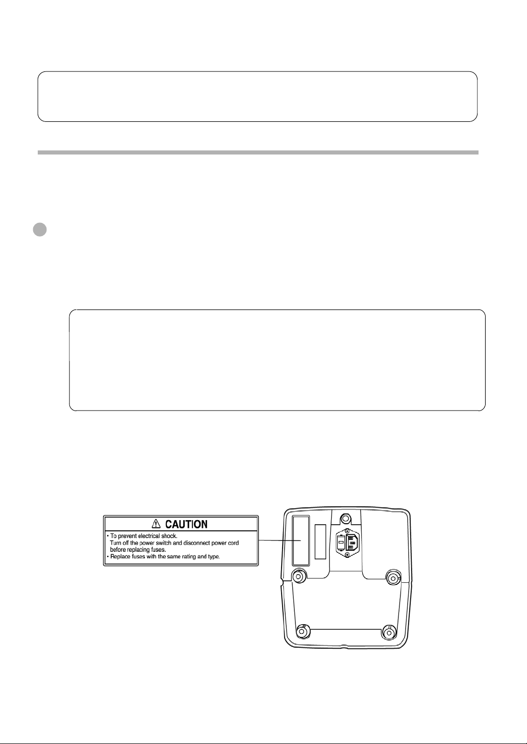
WARNING INDICATIONS AND POSITIONS
To insure safety, warning labels are provided.
Use the equipment correctly by following the warning instructions. If any of the following
labels are missing, please contact us at the address stated on the back cover.
3
Page 5

CONTENT
INTRODUCTION
DISPLAY FOR SAFE USE
SAFETY PRECAUTIONS
USAGE AND MAINTENANCE
ESCAPE CLAUSE
WARNING INDICATIONS AND
POSITIONS
COMPONENTS
COMPONENT NAMES
ACCESSORIES
TV MONITOR
1
2
AXIS MARKING
PRINTING THE ADDITIONAL
TEXTBOX (WITH - PRINTER TYPE)
19
21
2
SETTING A SEQUENCE NO.
22
3
ABBE COMPENSATION
3
FUNCTION
LENS PROTECTION PAD
22
22
3
MAINTENANCE
MAINTENANCE
23
5
BEFORE REQUESTING
5
SERVICE
CAUTION MESSAGES
25
MONITOR SCREEN
MENU SCREEN
MENU LIST
USING THE INSTRUMENT
PREPARATION
SETTING THE PAPER
(WITH - PRINTER TYPE)
MEASURING
4
10
10
11
6
8
9
CHECK ITEMS
SPECIFICATIONS
SPECIFICATIONS
WITH - PRINTER TYPE
OPTIONAL ACCESSORIES
25
26
26
26
USING THE INSTRUMENT
AS A SYSTEM
ON - LINE SYSTEM
27
Page 6
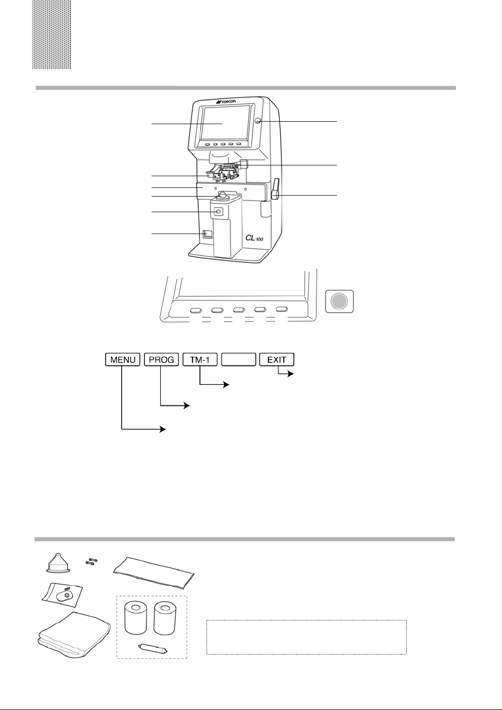
COMPONENTS
COMPONENT NAMES
TV Monitor
Lens retainer
Lens table
Lens support
MEMORY button
Power supply
(3)
(2)(1)
(5)(4)
BRIGHT control dial
Axis marker lever
Lens table lever
(6)
(1) Mode buttons Pressed to change the mode, and when pressed;
Returns to the initial state.
Pressed on to connect the spectral transmittance
meter (optional).
if a progressive lens is known, this begins the far vision
power measurement.
brings the Menu screen.
(2) TRANS button Used to change (+) to (−) and vice versa in displayed cylinder
value.
(3) R/L button Used to designate R for right lens or L for left lens.
(4) CLEAR button Used to delete memory data.
(5) PRINT button Press to output RC-232C data.
Press to print out the measurement data. (with printer-type)
(6) MEMORY button ● Used to store the measurement data.
ACCESSORIES
(A)
(E)
(B)
(C)
(D)
(F)
(A) Contact lens support .....................1 set
(B) Lens protection pad.......................1 set
(C) Dust cover .....................................1 pc.
(D) Silicon cloth ...................................1 pc.
(E) Fuse............................................. 2 pcs.
WITH-PRINTER TYPE
(F) Printer paper ................................ 2 rolls
(G) Printer paper shaft ........................1 pc.
(G)
5
COMPONENTS
Page 7
TV MONITOR
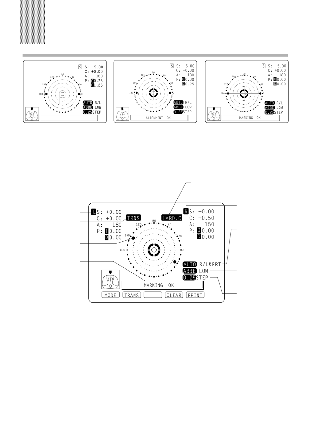
MONITOR SCREEN
Optical center’s off.
[OFF CENTER] is displayed
when the optical center is off
by 4∆ or more.
Left-eye lens
Transpose
Axial angle (every 5°)
OFF CENTER
ERROR
ALIGNMENT OK
MARKING OK
[ALIGNMENT OK] appears
when the lens is ready for
measurement.
Place + in center [MARKING
OK] appears, and the lateral
line will extend, getting the
instrument ready for marking.
HARD.C (HARD CONTACT)
SOFT.C (SOFT CONTACT)
PAD (LENS PROTECTION PAD)
Right-eye lens
(Inversion indicates a
storage status.)
AUTO R/L on status
(auto memory and auto R/L
switching)
When AUTO is displayed
inversion, R/L is automemory
off.
AUTO PRINT waiting status
When a high-refraction
lens diopter is
compensated
Step
6
TV MONITOR
Page 8
Enlargement:
When MENU/DISPLAY/HORIZONTAL LARGE is selected, the SCA display is
horizontally enlarged to make it easier to see.
When MENU/DISPLAY/VERTICAL LARGE is selected, the SCA display is vertically
enlarged to make it easier to see. The graphic moves to the opposite side.
Screen print display: (when enlaraged )
For framed lenses, of which both R and L are memorized, pressing the PRINT button
enlarges the SCA of both eyes. To return to the original state, press the EXIT button.
7
TV MONITOR
Page 9
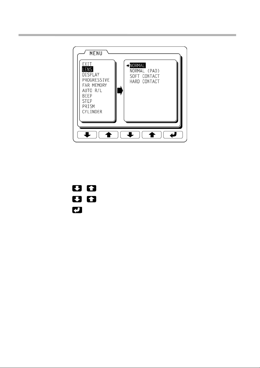
MENU SCREEN
To display the “MENU” screen, press the “MODE”
button then the “MENU” button.
Icons will appear at the bottom of the screen.
Refer to the buttons at the bottom of the screen to
scroll through the Menu.
Selects a menu.
Selects the contents of each menu.
Changes the setting, and return to
the measurement screen.
8
TV MONITOR
Page 10

MENU LIST
EXIT Returns to the initial state without changing settings.
LENS NORMAL Measures a normal lens.
NORMAL (PAD) Measures a normal lens wearing a lens protection seal.
SOFT CONTACT Measures a soft contact lens.
HARD CONTACT Measures a hard contact lens.
DISPLAY HORIZONTAL LARGE Horizontally enlarges the SCA display.
VERTICAL LARGE Vertically enlarges the SCA display.
NORMAL Normal display
PROGRESSIVE OFF Auto progressive judgment mode OFF.
AUTO Auto progressive judgment mode ON.
PROGRESSIVE ONLY Always begins the far vision power measurement of a
progressive lens.
REVERSE Measures the diopter power with the concave side up.
FAR MEMORY ON Auto memory of far vision power measurement.
OFF Manual memory of far vision power measurement.
AUTO R/L ON-R/L Measurement of framed lens: Auto R/L switching and auto
memory.
ON-S/R/L Measurement of single lens/framed lens: Auto R/L switching
and auto memory
OFF Auto memory OFF
BEEP ON Buzzer sounds when a measured value is stored and a
button is pushed.
OFF Buzzer OFF
STEP 0.25 0.25-step measurement.
0.12 0.12-step measurement.
PRISM NO DISPLAY No prism display.
X-Y Coordinate display
P-B Polar coordinate display
mm mm display
CYLINDER MIX Mixed display
+ Plus-fixed display
- Minus-fixed display
ABBE NORMAL 50-60 Abbe
MID 40-50 Abbe
LOW 30-40 Abbe
AUTO OFF YES Power save ON
NO Power save OFF
RS-232C NEW FORMAT External output (NEW FORMAT)
OLD FORMAT External output (OLD FORMAT)
STD1 External output (STD FORMAT)
TM-1 Pressed on to connect the spectral transmittance meter
(optional).
SEQ.NO. SET Serial No. print mode
with-printer Type (added to the above)
PRINTER ON Printer output ON
OFF Printer output OFF
AUTO PRINT ON Auto memory output (S: When the lens is removed
R/L: When both lenses are the same class (1st/2nd near
vision power of far vision power)
OFF Manual memory output
NAME SET Shop name print mode
TV MONITOR
9
Page 11

USING THE INSTRUMENT
PREPARATION
Remove the tape from the lens support.
1
Remove the tape from the marking ink cartridge.
2
Connect the power cable to the body.
3
Turn on the power switch ( O → − ).
4
SETTING THE PAPER (WITH-PRINTER TYPE)
Remove the printer cover and slide the paper into the slit until it comes out from the
1
outlet, as illustrated.
Keep the lever at the top position.
2
Take care of the roll direction.
Pass the printer paper shaft through the paper to load the printer with paper.
3
Set the printer cover.
4
Lower the lever to the bottom position.
5
Press
PRINT
button
while
pressing
CLEAR
Lever
• Do not install the instrument in a place which is exposed to direct sunlight, high
temperature and humidity and dust.
• Do not install the instrument at a place exposed to intense light or on a glossy table.
• The instrument may not operate properly or “ERROR” may be displayed.
• Use a power of AC100, 120, 220, 240V/±10% (50/60Hz)
button.
Shaft
10
USING THE INSTRUMENT
Page 12

MEASURING
Checking before measuring
Connect the power plug with a power outlet.
1
Check to see that there is no lens on the lens support.
2
Turn on the power switch, and display will appear on the screen in a few seconds.
3
INITIAL ERROR will appear when power is turned on with a lens on the lens support.
Measuring a single lens
Place the target lens with the concavity downward.
1
Lift and place down the lens retainer to retain the target lens with an accompanying
2
hand.
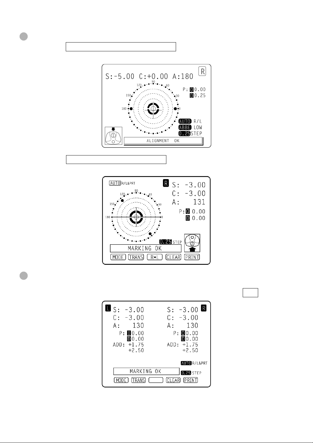
ALIGNMENT OK will be displayed when the target image center is within the
3
minimum circle (0.5∆ or smaller).
The ALIGNMENT OK mark is displayed when the target image center is reached. In
4
the case of S measurement with AUTO R/L on (AUTO being inverted), “single
lens” is memorized automatically. When BEEP is ON, the buzzer sounds.
(Note) The target may move in a contrary manner immediately after the lens is
placed.
Changing measuring steps
1
Select on the menu screen [0.12] or [0.25].
When prism display is needed
2
Set as follows in the Menu screen:
[NO DISPLAY] ............. No display
[X-Y] ............................. Orthogonal coordinates display
[P-B] ............................. Polar coordinates display
[mm] ............................. Display by mm
11
USING THE INSTRUMENT
Page 13

When diopter transposition is required
3
Press TRANS button, and the astigmatism
symbols will change.
Press the button again, and the original data
will reappear.
When storing
4
Press the MEMORY button ●. S will turn to S .
When R/L designation is required
Press the R/L button.
In the screen, S R L appears in this order.
For example, S R now after pressing is displayed.
When printing
5
Press PRINT button.
Measuring a framed lens
Turn the lens table lever and bring it before you.
1
Gently, place the glass frame against the lens
2
table for measurement.
Alignment
Right and left......... Place the frame against the
Vertically ............... Move the table easily with the
When AUTO R/L is off (neither AUTO R/L nor AUTO R/L is displayed)
•
Press the S R button.
First align the right lens and press the Memory button ●.
Press the R L button.
Align the left lens and press the Memory button ●.
When AUTO R/L ON-/R/L is set (AUTO R/L is displayed):
•
*Measurement of single lens.
At first, align the right lense to display “MARKING OK”. Then the result is
automatically memorized, when the right lense is hold.
Removing the right lens will automatically move to the L measurement.
Align & hold the left lens. The result is automatically memorized.
When AUTO R/L ON-S/R/L is set ( AUTO R/L is displayed):
•
*Measurement of single lens/framed lens
Press the S R button.
At first, align the right lense to display “MARKING OK”. Then the result is
automatically memorized, when the right lense is hold.
Removing the right lens will automatically move to the L measurement.
Align & hold the left lens. The result is automatically memorized.
AUTO R/L: Both auto memory and auto R/L switching
AUTO R/L: Auto R/L switching only
To set AUTO R/L, set PROGRESSIVE/OFF and AUTO R/L/ON-R/L
or AUTO R/L/ON-S/R/L .
S: −1.50 S: −1.00
C: +0.50 C: −0.50
A: 90 A: 180
lens table gently, and move the
frame right and left finely.
lens table lever.
12
USING THE INSTRUMENT
Page 14

Judging a progressive lens
• Judging a progressive lens MENU screen/PROGRESSIVE/AUTO
Judges a single focal lens or a progressive lens, which otherwise is difficult.
Under this mode, a graphic operation procedure is displayed at the bottom left.
Select [PRGRSVE.] [PROGRESSIVE] with MENU button, and a
1
single focal lens will be told from a progressive focal lens, which
is not easy from appearance.
Under this mode, the graphic operation procedure appears at
2
the lower left on the screen.
Measure the lower frame center (position (1)); do not move the
3
frame during measurement.
Measure the upper frame center (position (2)); do not move the
4
frame during measurement.
Graphic
operation
procedure
Pressing the Mode button and then the PROG button will omit the auto progressive
judgment mode.
Or, when MENU screen/PROGRESSIVE/ PROGRESSIVE ONLY is designed, always
the far vision power measurement for progressive lens begins.
• Measuring a progressive lens for far vision power (excluding prism prescription lens)
The initial screen for far vision measurement shows the right
1
figure.
Move the glass frame to match + with
Move the glass frame according to the direction of the arrow.
2
.
13
USING THE INSTRUMENT
Page 15

After measuring the far vision region, the screen automatically switch itself to near
3
vision power measurement. (To facilitate detecting the far vision region, hold the lens
gently and more the lens slowly.)
Press the Memory button ●. Optionally store the result of far vision power measurement.
The screen switches to the near vision power measurement.
When MENU screen/FAR MEMORY/OFF is set, the result of far vision power
measurement is not automatically stored. Press the Memory button ●.
For high-power lenses, sometimes the far vision region cannot be detected so easily. In
this case, do measurement around the position shown in the right figure, and press ADD
button.
Measuring a progressive lens for near vision power
While watching the screen, bring the lens table foremost.
1
The maximum value remains in inversion
10mm approx.
Under the condition illustrated below, a position off the progressive zone is being
2
measured. Move the frame along the arrow.
14
USING THE INSTRUMENT
ADD value
Page 16
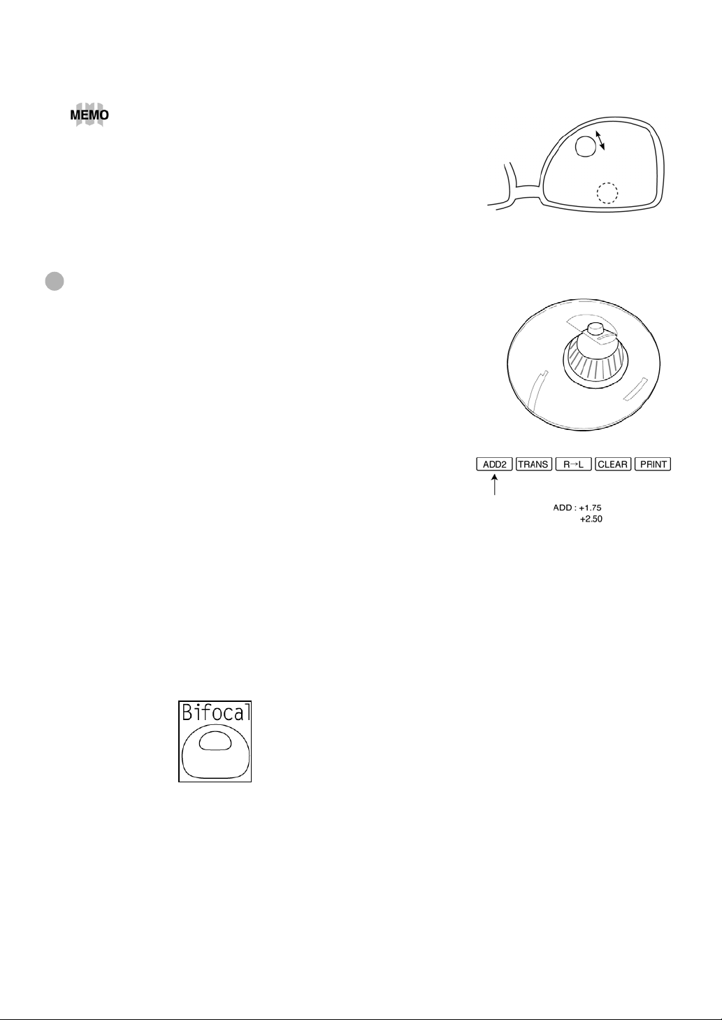
Within the progressive zone, press the Memory button at a position where the ADD
3
value is the maximum.
When measuring a lens mounted in a large frame, ADD
power may be higher because some lenses increase in
ADD power at a position lower than the near vision
region. If the lens is measured, accordingly, at a point
lower than the near-vision eye point, ADD power may
be higher. If you want to know the previous
prescription, it is advisable to check the measurement
position with *** mark.
Measuring a bi- and tri-focal lens
When using progressive graphics from the auto
•
progressive judgment mode:
Set the bottom center of screen under the Auto
progressive judgment mode (position (1)) to the near
vision power region (near segment) and measure the
lens at rest. Upon measuring the far vision power
region at rest in like measuring a progressive lens,
the screen automatically switches to the far vision
power measurement.
When measuring the 2nd near vision power of tri-focal lenses, memorizing the 1st
near vision power changes the mode button to the
ADD2 button. Pressing the button starts the 2nd
diopter power measurement.
When marking the optical center of far vision power
•
region:
Align the far vision power region and press the MEMORY button ●.
1
Mark the optical center.
2
Set the screen to the near vision power region (near segment).
3
Press the MEMORY button ● (in this case the MEASUREMENT OK button of near
4
vision power).
The mark shown left is displayed on the screen.
Measure the near vision power and press the MEMORY button ●.
5
15
USING THE INSTRUMENT
Page 17

Measuring an unprocessed progressive lens
As each unprocessed lens has a mark on the measuring point. Do measurement on the
mark position. For measurement, follow the procedure of “Judging a progressive lens,
measuring a progressive lens for far vision power” and “Measuring a progressive lens
for near vision power”.
Far vision region marked
Near vision region marked
The measuring point for the far or near vision region may be narrowed by marks. Take
care that the luminous flux may not be shaded during measurement.
ADD values will flicker when the luminous flux is shaded by marks or off the progressive
zone at the time of measuring the near vision region. An EX lens may not be provided
with accurate measurements when measured in the boundary.
Mode to measure the diopter power of lenses with the concave side up
Set MENU/PROGRESSIVE/REVERSE .
1
Lens position Screen
Set the lens with the concave side down
2
as usual, align the far vision power
region, and press the MEMORY button.
Set the lens with the concave side up,
3
align the far vision power region, and
press the MEMORY button.
Leaving the lens with the concave side
4
up, align the near vision power region
and press the MEMORY button.
16
USING THE INSTRUMENT
Page 18

Measuring a contact lens
• Measuring a hard contact lens
Replace the lens support with the contact lens support.
1
Select [LENS] [HARD CONTACT] from the menu, and HARD.C will be displayed on
2
the screen.
Carefully with a tweezer, place the target contact lens on the plate and fit it as is.
3
Tweezer
17
USING THE INSTRUMENT
Page 19
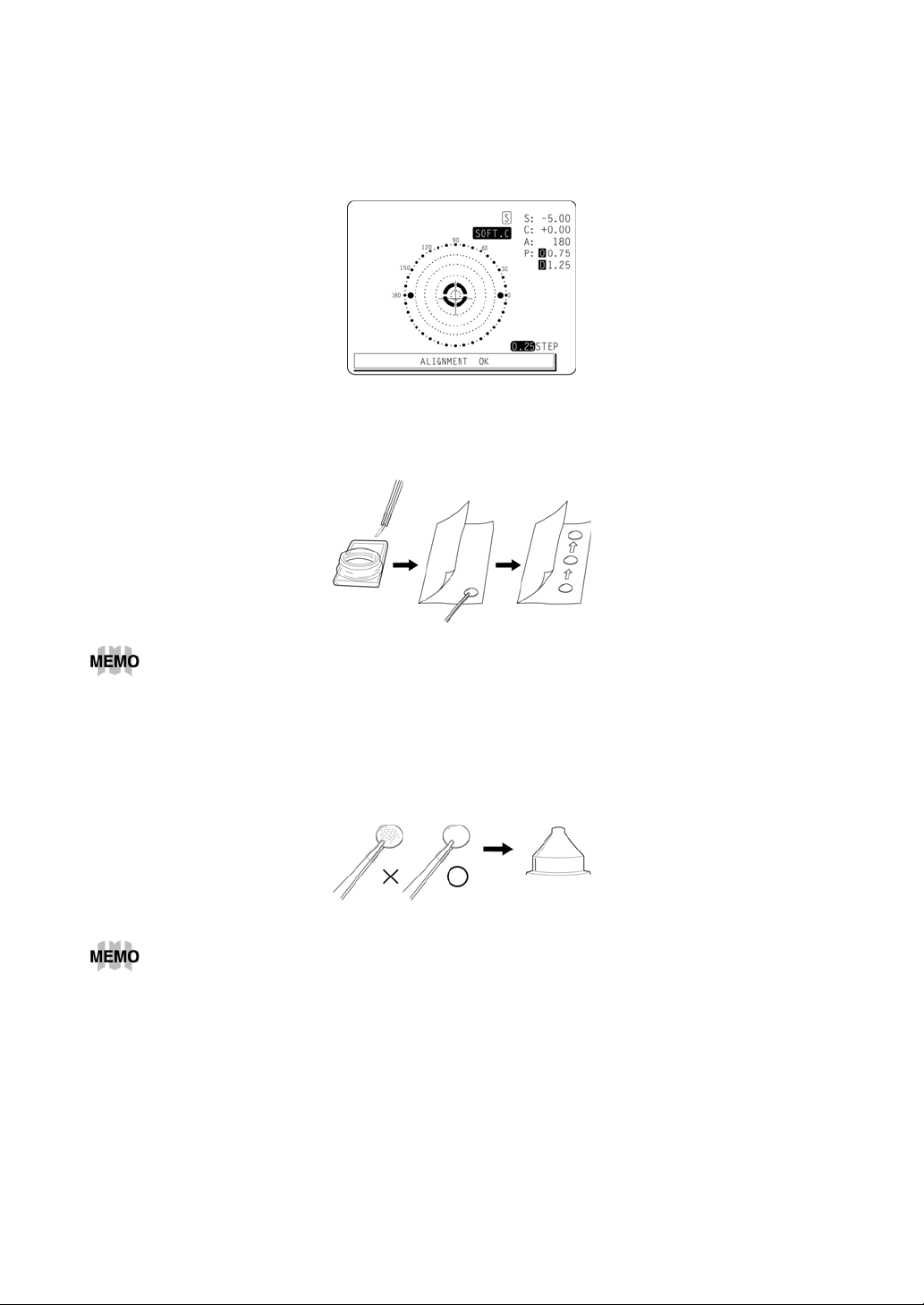
• Measuring a soft contact lens without astigmatism
Use the contact lens support for measuring as measuring a hard contact lens.
1
Select [LENS][SOFT CONTACT] from the menu, and SOFT CONTACT will appear
2
on the screen.
Pinch the target soft contact lens with special tweezers to swish off moisture from the
3
lens. Put the lens between paper to remove moisture from the surface.
If you observe dews on the soft contact lens surface, measurement will not be possible
because the luminous flux gets out of order.
If there are dews on the surface when the target contact lens is held to the light, put
4
the lens in the special solution again, and repeat the above. If the lens is ready for
measurement, put it on the contact lens holder and tell the shape (with tweezers) for
alignment.
Use the hard contact mode when measuring a soft contact lens with astigmatism.
18
USING THE INSTRUMENT
Page 20
AXIS MARKING (CARTRIDGE SPECIFICATION/STEEL NEEDLE SPECIFICATION)
Using the cartridge, one light touch to the lens can put a clear ink mark.
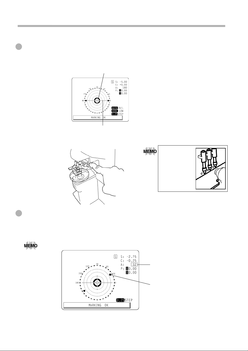
Marking a lens without astigmatism
Move the target lens until the centering mark coincides with the target image
1
completely, and MARKING OK will appear.
Centering mark
Line extends laterally to the target.
Depress the marking lever to mark the lens.
2
Ensure the ink
cartridges do
not interfere
with the lens
Marking a lens with astigmatism
Axis marking, maintaining the axis as prescribed
1
Align the target image with the center mark, approximating the axis angle mark to the
angle as prescribed.
Do it with AUTO R/L off.
Check here
Axis angle mark (every 5°)
19
USING THE INSTRUMENT
Page 21
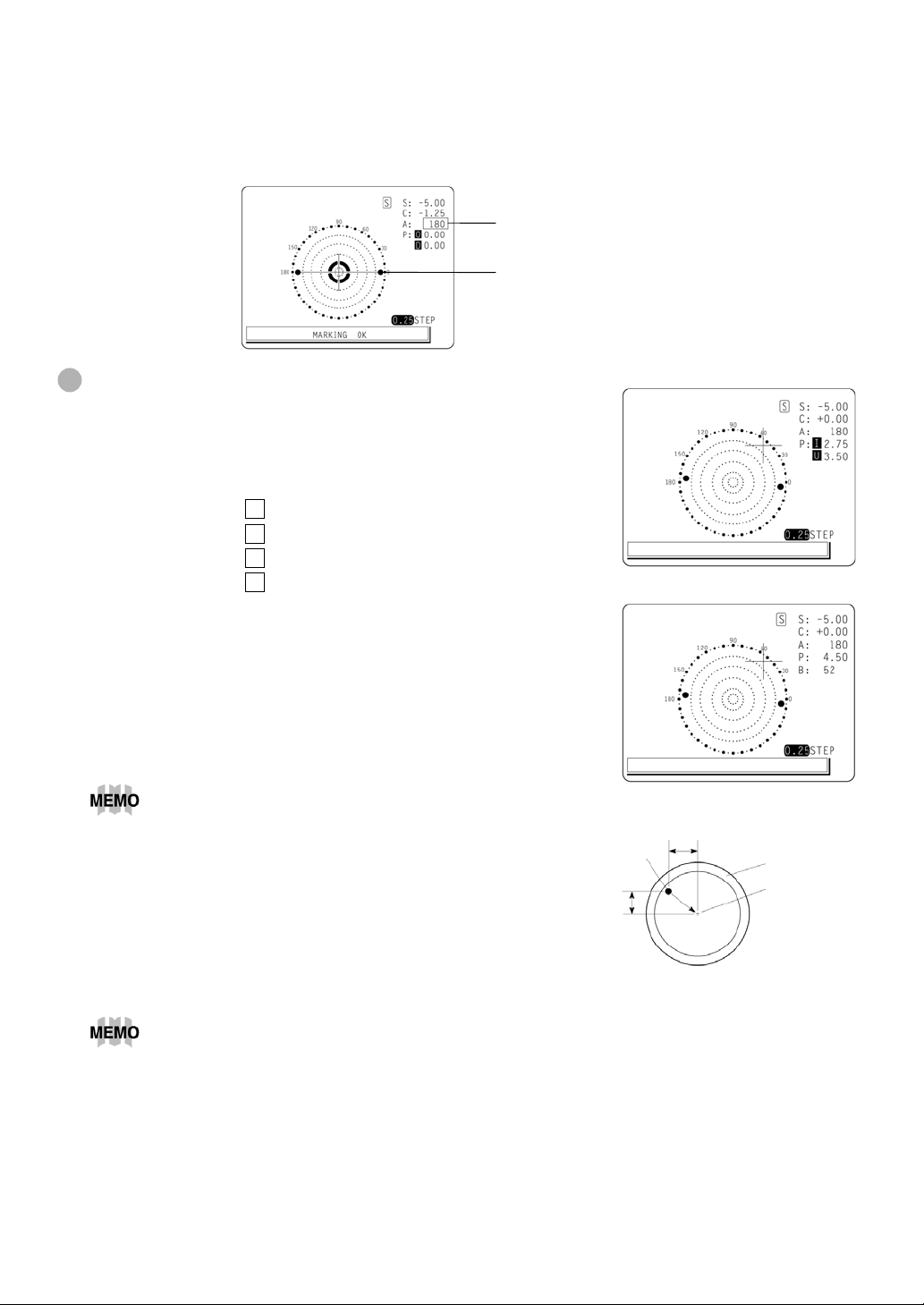
Marking a cylindrical axis
2
Match the center mark with the target image, approximating the axis angle mark to
180 degrees.
Adjust A of the axis angle to 180 degrees.
Marking a lens with prism power
• When the prescription is displayed with X-Y
(orthogonal coordinates):
Select [PRISM][X-Y] from the menu.
Carry out aligning according to the prism value as
prescribed and as displayed on the screen.
I in prism value: Base In
O in prism value: Base Out
U in prism value: Base Up
D in prism value: Base Down
• When the prescription is displayed with P-B (polar
coordinates)
Select [PRISM][P-B] from the menu.
Carry out aligning according to the prism value as
prescribed and as displayed on the screen.
P: Prism value
B: Base orientation
Adjust to 180°.
Axis angle mark (every 5°)
Take care that the polar coordinates are not the same as the value on the angular scale
in the target image.
• When the unit is mm.
Select [PRISM][mm] from the menu.
The ↑ ↓ ← → marks show the optical center
reaches the center of measurement by
moving the target lens in the arrow directions
by the distance as displayed.
→ 3.0mm
↓ 2.0mm
0 will be displayed if the spherical power S is around 0.
20
USING THE INSTRUMENT
Optical center
2mm
3mm
Lense
support
Center of
measurement
Page 22
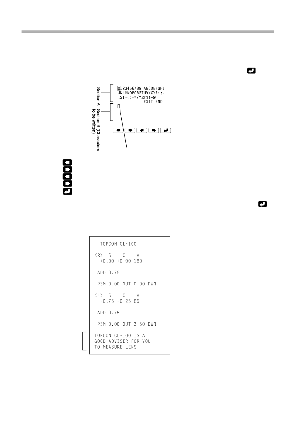
PRINTING THE ADDITIONAL TEXTBOX (WITH-PRINTER TYPE)
On the print out with the measuring data, the user can input his own text, like the name
of shop, address or special message. Available space is three line of 20 characters
each.
Select NAME SET from the menu and press the button below the icon
, and the
world of marking of text will appear (as shown at below).
Cursor 20 character x 3 rows
: Moves to the left the cursor in Section A.
: Moves to the right the cursor in Section A.
: Moves to the left where to write in Section B.
: Moves to the right where to write in Section B.
: Writes the character in Section B.
Upon completing Section B, move the cursor to END of Section A and press
, and
writing may be possible, returning the measurement screen. Once the characters are
written, they will remain even after the instrument power is turned off.
Printout
Printing
the
additional
textbox
21
USING THE INSTRUMENT
Page 23
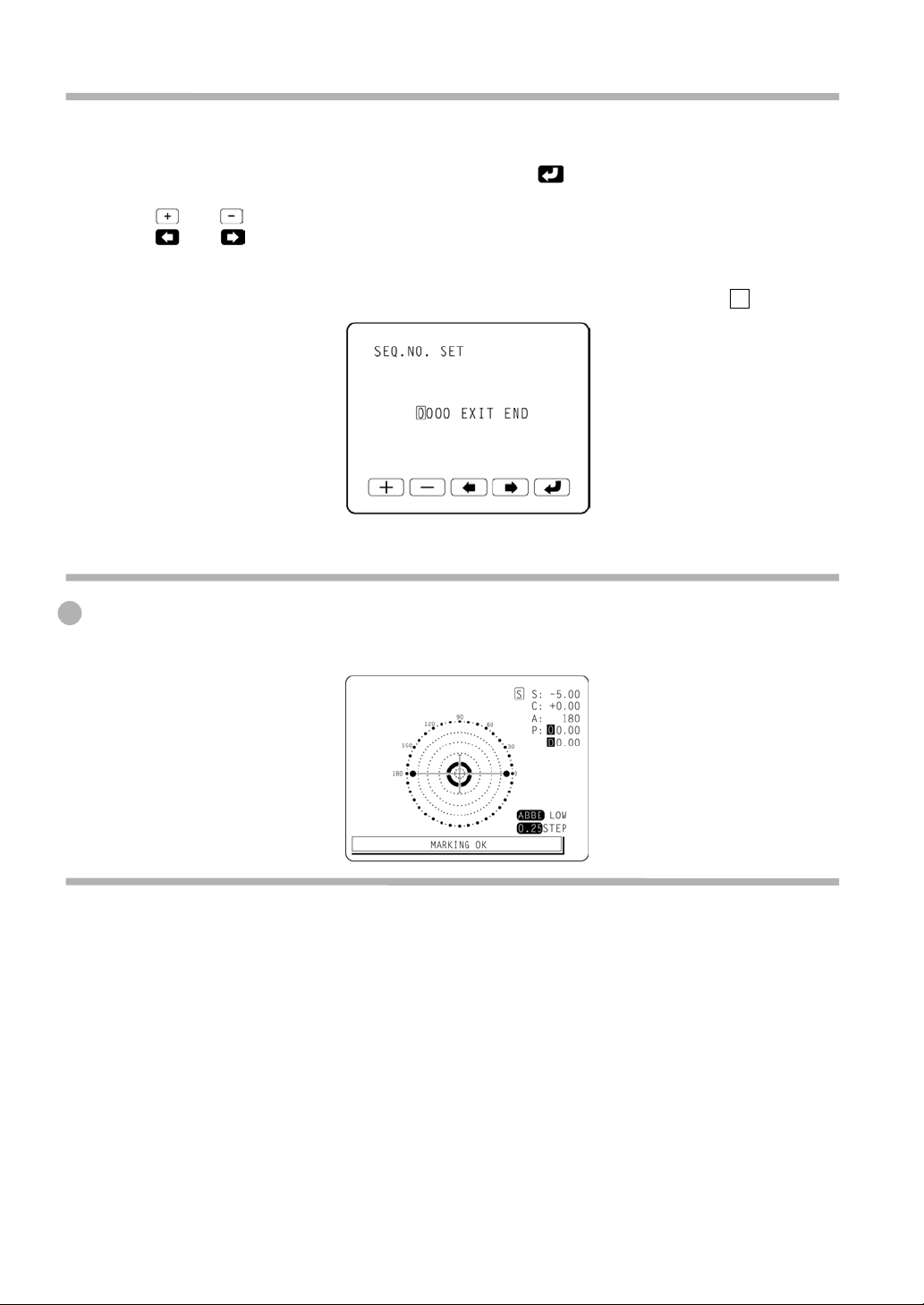
SETTING A SEQUENCE NO.
Setting is carried out when writing a sequence No. on printing paper and transferring the
serial No., using RS232C.
Select SEQ. NO SET from the menu and press
appear.
and are used to change the cursor figure.
and are used to change the cursor position.
Bring the cursor to END and press A to finish setting.
No printing or counting is carried out in case of 0000. Press MEMORY, PRINT. and
CLEAR buttons in this order. and counting will be carried out. (except for S single lens).
ABBE COMPENSATION FUNCTION
, and the screen as shown below will
When the Abbe number of lens is known:
In the menu screen ABBE, select any of the following according to the Abbe number of
target lens:
Normal (50-60)
MID (40-50)
LOW (30-40)
Lens protection PAD
The attached lens protection pad allows a soft contact with the measuring lens.
Fit the lens protection pad according to the instructions.
1
Select [LENS][NORMAL(PAD)], and the measurement result will be automatically
2
compensated.
22
USING THE INSTRUMENT
Page 24
MAINTENANCE
Auto shut-off
The monitor screen will shut off automatically if not in use for about 10 minutes.
1
Press any button, and the instrument will resume.
2
Select MENU screen/AUTO OFF/NO from the menu if it is not desirable.
3
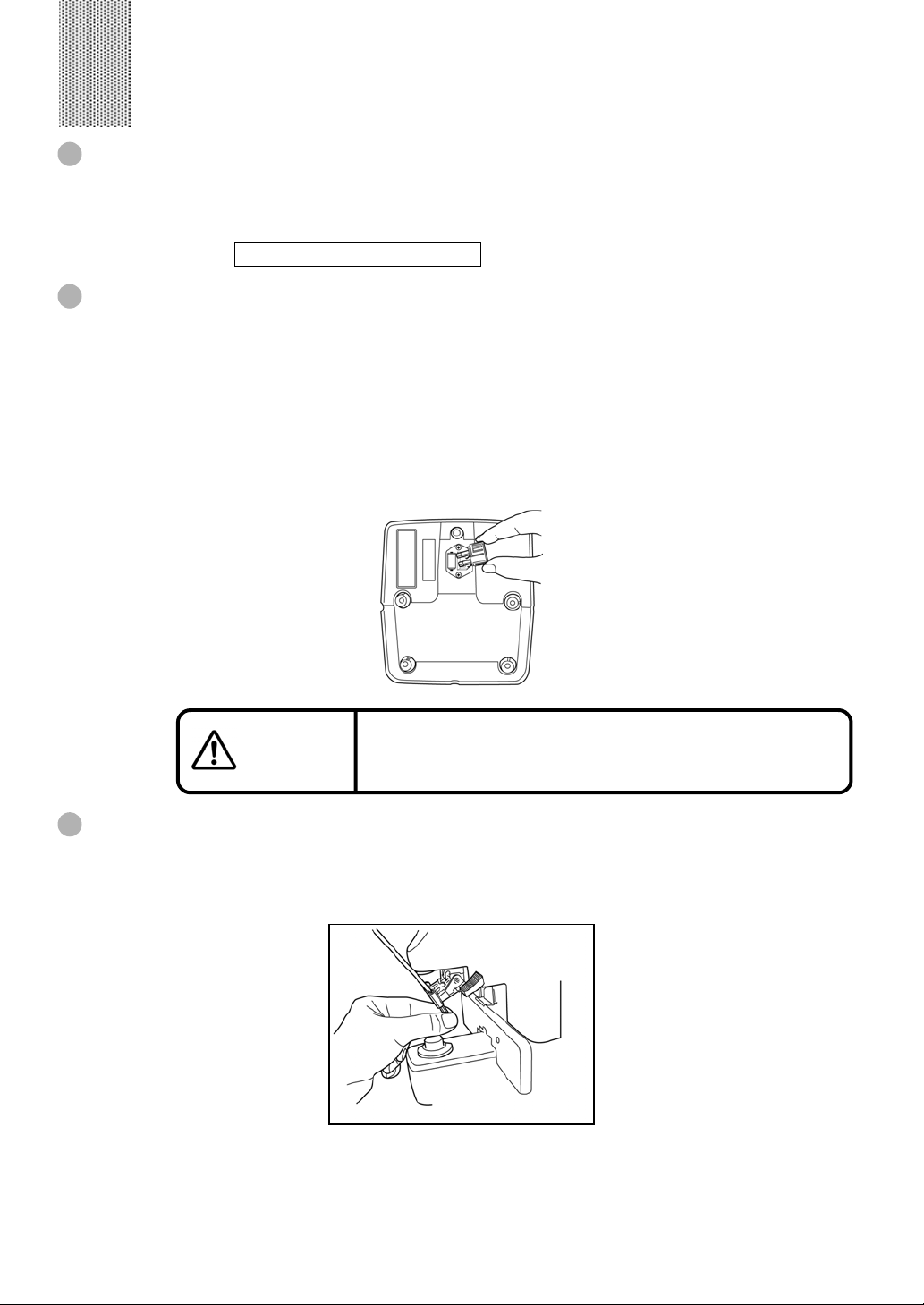
Fuse
(Note) To prevent electrical shock, turn off the power switch and disconnect power cord
before replacing fuses.
The fuse holder is provided at the bottom part of the instrument.
1
Disconnect the power cable.
2
To remove the cover, push the top and bottom pawls simultaneously, using 2 screw
3
drivers.
A 1.6A (250V) glass tube fuse is provided in the holder.
4
To prevent electrical shock, turn off the power switch and
CAUTION
Replacing the marking ink cartridge (the same applies to the optional steel needle)
To replace the marking ink cartridge, remove the top screw does. Pull out the
1
cartridge while applying pressure to it so as the spring not jump out from the inside.
Work the lens holder/stopper under the lowered condition.
disconnect power cord before replacing fuses.
Replace fuses with the same rating and type.
MAINTENANCE
23
Page 25
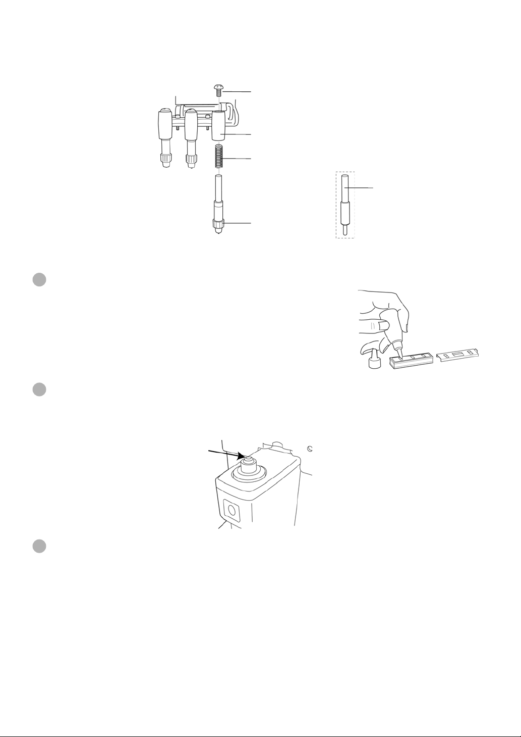
To set the cartridge, insert the spring and keep the cartridge top well above the
2
marking ink holder, and then fasten the screw.
Supply of ink for the optional steel needle
Replenish ink when poor marking happens.
1
Slide laterally and pull out the inkpot.
2
Slide off cover from the inkpot.
3
Screw
Marking ink holder
Spring
Steel needle
(optional accessory)
Marking ink cartridge
Infiltrate replenish ink into the sponge well.
4
Cleaning cover glasses
If the glass is dirty as indicated by arrows, it will affect measurement accuracy adversely.
If this occurs, clean them with the attached silicon cloth.
Remove the lens support before cleaning the cover glass.
Cleaning the instrument
Wipe cover with silicone or damp cloth, never use cleanser or other chemicals.
1
24
MAINTENANCE
Page 26

BEFORE REQUESTING SERVICE
CAUTION MESSAGES
DIOPTER OVER
PRISM OVER’
ERROR
INITIAL ERROR Request repair service.
PAPER END (with printer-type) Printer paper is out. Load new paper.
PRINTER HEAD UP
(with-printer type)
Check to see that the target lens is in the measurable
scope.
Check to see that the target lens is free from any flaw, dust
or oil.
Clean both glasses and turn power on again.
Check the lens value is not beyond the unit’s measuring
range.
Remove the lens from the lens support, and turn on power
again.
The printer lever is Up. Lower the printer lever.
CHECK ITEMS
The instrument does not get ready for
operation even if the power switch is
turned on.
The monitor screen is not visible well. Adjust the Bright adjustment dial.
S, C values are wrong. Is the lens place with power off?
Marking is poor. Replace the marking ink cartridge. For a lens with
The screen went out all of a sudden. The auto shut-off function is on.
Pushed the Print button but the printer
does not work. (with-printer type)
Re-plug the power cord.
Give a check to the fuse.
Remove the lens and turn on power again.
Is the beam blocked by an unusual flaw, dust, mark,
grease, etc. in the measured lens?
sharp surface curve, use the optional steel needle
marking set.
Press the any button ●, and the instrument will
resume.
Is printer paper set properly?
Not inside out?
25
BEFORE REQUESTING SERVICE
Page 27

SPECIFICATIONS
SPECIFICATIONS
Measurable scope S: 0~±25D C: 0~±10D ADD: 0~+10D (0.12/0.25)
P: 0~10∆ (0.12/0.25) A: 1~180° (1°)
Cylinder mode
Prism mode No display / X-Y (orthogonal coordinates) / P-B (polar coordinates) / mm
Contact lens Hard and soft contact lenses are measurable.
Progressive focal lens Single focal/progressive lens judgment, far vision power detection, ADD
Compensating Compensation of a lens different in Abbe number.
Display screen
Frame Auto R/L function
Menu screen Easy-to-watch screen with icon display
Target lens diameter Ø5 ~ 100mm
Power supply 100/120/220/240V 55VA (Auto shut-off in 10 minutes)
Dimensions, weight
Environment condition : Indoor use Altitude up to 2,000m
MIX/−/+
A contact lens plate and a fine-movement ring provided.
power bar-meter display
LCD 300 × 240 dots S, C, A, P, ADD, ADD R/L display en bloc.
Enlarged SCA display.
( CE marking: only 230V )
215 (W) × 220 (D) × 420 (H) 6.5kg approx.
* Subject to changes in design and/or specifications, without advanced notice.
Pollution degree II Temperature 5~40°C
Maximum relative humidity 80% for temperatures up to 31°C decreasing
linearly to 50% relative humidity at 40°C
WITH-PRINTER TYPE
Printer: Thermal printer, paper width 58mm
OPTIONAL ACCESSORIES
Steel needle marking set (steel needle, supply ink, ink bottle, holder)
Ordering consumable supplies and spares
Product name Part code No. Remark
Spare part 100~120V Fuse (250V, 1.6A)
220~240V Fuse (250V, 1.0A)
Consumables Marking ink cartridge (3 cartridges/set) 4203699500 Standard accessory
Lens protection pad 4203656000 Standard accessory
Steel needle marking set 4203625100 Optional accessory
Supply ink 4203690060 Optional accessory
Printer paper 4480040010 With-printer type
0514111620
0514110130
Standard accessory
Standard accessory
26
SPECIFICATIONS
Page 28

USING THE INSTRUMENT AS A SYSTEM
ON - LINE SYSTEM
The data of computerized lensmeter can be transfered to the instruments through RS232C interface, and also measuring data of the instruments can be transfered to
computerized visiontester.
COMPUTERCVRM/KRCL
27
USING THE INSTRUMENT AS A SYSTEM
Page 29

COMPUTERIZED LENSMETER
CL-100
TOPCON AMERICA CORPORATION
CORPORATE OFFICE:37, West Century Road, Paramus, New Jersey 07652, U.S.A. Phone: 201-261-9450 Fax: 201-387-2710
TOPCON OMNI SYSTEMS, INC.
Valley Forge Business Center, 2430 Blvd. of the Generals, Norristown, PA 19403, U.S.A Phone: 610-630-9200 Fax: 610-630-6428
TOPCON EUROPE B.V.
(European Representative)
Esse Baan 11, 2908 LJ Capelle a/d IJssel, The Netherlands. Phone: 010-4585077 Fax: 010-4585045
TOPCON S.A.R.L.
HEAD OFFICE:104/106, Rue Rivay 92300, Levallois-Perret, France. Phone: 01-41069494 Fax: 01-47390251
LYON OFFICE:138, Avenue du 8 Mai 1945, 69100 Villeurbanne, France Phone: 0478688237 Fax: 0478681902
TOPCON DEUTSCHLAND G.m.b.H.
Halskestr. 7, 47877 Willich, Germany. Phone: 02154-9290 Fax: 02154-929-111 Telex: 8531981 TOPC D
TOPCON ESPAÑA S.A.
HEAD OFFICE:Frederic Mompou 5, 08960 Sant Just Desvern Barcelona, Spain. Phone: 03-4734057 Fax: 03-4733932
MADRID OFFICE:Avenida Ciudad de Barcelona 81, 1 Planta 28007, Madrid, Spain. Phone: 01-552-4160 Fax: 01-552-4161
TOPCON SCANDINAVIA A. B.
Industrivägen 4 P. O. Box 2140 43302 Sävedalen Sweden. Phone: 031-261250 Fax: 031-268607
TOPCON (GREAT BRITAIN) LTD.
Topcon House,Kennet Side,Bone Lane,Newbury,Berkshire RG14 5PX United Kingdom Phone:01635-551120 Fax:01635-551170
TOPCON SINGAPORE PTE. LTD.
Alexandra Distripark Block 4, #05-15, Pasir Panjang Road, Singapore 118491 Phone: 2780222 Fax: 2733540 Telex: 61121 TOPSIN
TOPCON INSTRUMENTS (MALAYSIA) SDN. BHD.
Lot 226 Jalan Negara 2, Pusat Bandar Taman Melawati, Taman Melawati, 53100, Kuala Lumpur, Malaysia. Phone: 03-4079801 Fax: 03-4079796
TOPCON INSTRUMENTS (THAILAND) CO., LTD.
77/162 Sinn Sathorn Tower, 37th Fl.,Krungdhonburi Rd.,Klongtonsai, Klongsarn, Bangkok 10600 Phone: 662-440-1152~7 Fax: 662-440-1158
TOPCON AUSTRALIA PTY. LTD.
408 Victoria Road, Gladesville, NSW 2111, Australia Phone: 02-9817-4666 Fax: 02-9817-4654
TOPCON KOREA CORPORATION
Hyobong Bldg., 1-1306, Seocho-Dong, Seocho-Gu, Seoul, Korea. Phone: 02-557-9231~2 Fax: 02-556-1928 Telex: K23231 EXT2264
TOPCON OPTICAL (H.K.) LIMITED
2-4/F Meeco Industrial Bldg, No. 53-55 Au Pui Wan Street, Fo Tan Road,Shatin, N.T., Hong Kong Phone: 26901328 Fax: 26910264
TOPCON CORPORATION BEIJING OFFICE
Room No. 962 Poly Plaza Building, 14 Dongzhimen Nandajie Dongcheng District, Beijing, 100027, China Phone: 10-6501-4191~2 Fax: 10-6501-4190
TOPCON CORPORATION BEIRUT OFFICE
P. O. BOX 70-1002 Antelias, BEIRUT-LEBANON. Phone: 961-1-521119 Fax: 961-1-521119
TOPCON CORPORATION DUBAI OFFICE
Office No.102, KHALAF RASHD AL NAYLI BLDG., Deira, Dubai, UAE Phone: 971-4-696511 Fax: 971-4-695272
TOPCON CORPORATION
75-1 Hasunuma-cho,Itabashi-ku,Tokyo,174-8580 Japan
Phone:3-3558-2520 Fax:3-3960-4214
 Loading...