

Page 1
QUICK MANUAL
LCD Computerized Chart
CC-100 Series
REV. 10 2012
Page 2

NOTE
Selecting externally connected equipment
The CC-100 Series Computerized chart complies with European Medical Device Directive and bears the CE
marking.
Before connecting a external device to the CC-100 Series product make sure that such external equipment
is in compliance with EN 60950-1 and CE marking.
This manual is referred to device with 3.4.x software version.
Manufacturer
VISIA imaging S.r.l.
Via C. E. Gadda, 15
52027 San Giovanni Valdarno (AR)
Italy
Distributor
Topcon Europe Medical B.V.
Essebaan 11
2908 LJ Capelle a/d IJssel
The Netherlands
www.topcon.eu
medical@topcon.eu
2
Page 3

INTENDED USE
Utilisation
The CC-100 Series device is a instrument for the analysis of visual acuity.
The CC-100 Series device is able to execute the principal and most important visual tests: acuity, binocular
vision, contrast sensitivity, and more.
The entire display screen is capable to display standard visual acuity tests and dissociated tests too.
The instrument display is commanded through an infrared remote control or through a direct connection with
Topcon automated phoropters.
In comparison to the classical chart projectors, the PC functions allows for greater flexibility and more
advanced functions.
Users
Oculists, ophthalmologists, opticians, optometrists.
The device must be uses by qualified personal.
Type of Environment where it could be use in
Ambulatory, physicians studios, opticians shops.
3
Page 4
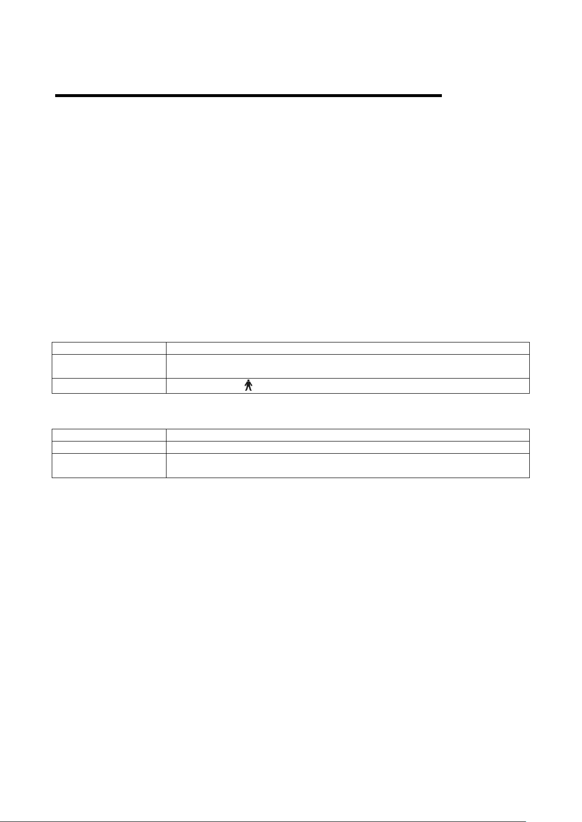
PRECAUTIONS
Trade mark
CE
93-42 EC Directive
Classification
Class I
IEC 601-1 Classification
Class I, type B
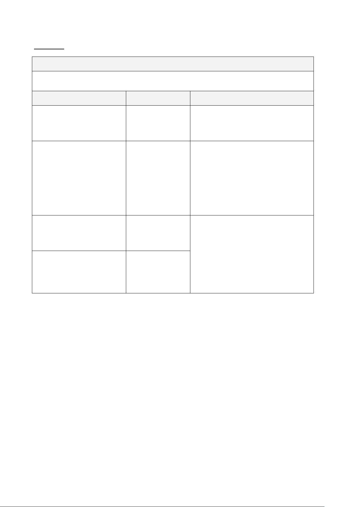
Power Supply
AC 110-120 V or 220-240V -- 50-60 Hz
Power Absorption
120VA
Fuses
220-240 V: 20x5mm 2.5A Antisurge
This instrument is an electronic precision unit, so be sure to use and store it in a place controlled under
normal living temperature, humidity and atmospheric pressure, and avoid direct exposure to sunlight.
To ensure right operation, install the instrument on the wall and check for a precise horizontal and vertical
alignment. Also do not put anything on top of the instrument.
To ensure an optimal coverage of polarized tests, align the center of LCD with the line of sight of the patient.
Wear the polarized or Red/Green lenses and select in CC-100 Series a dissociated test, check the horizontal
and vertical alignment until the best coverage for each eye is reached.
Connect all cables properly before using.
Use the power at a rated voltage.
When not in use, switch off the power source and protect the unit from sunlight and dust.
For accurate functioning, keep the instrument clean and free of spots and dust.
Technical Specifications :
Electrical Specifications:
Electromagnetic Compatibility
This product conforms to the EMC standard (IEC 60601-1-2:2007).
MEDICAL ELECTRICAL EQUIPMENT needs special precautions regarding EMC and need to be
installed and put into service according to the EMC information provided in the accompanying
documents.
Portable and mobile RF communications equipment can effect medical electrical equipment
The use of accessories and cables other than those supplied with the instrument, exception for
cables sold by the manufacturer of the equipment as replacement parts, may result in increase
emission or decrease immunity of the equipment or system.
The equipment or system should not be used adjacent to or stacked with other equipment. If
adjacent or stacked use is necessary, the equipment or system should be observed to verify normal
operation in the configuration in which it will be used.
4
Page 5
EMC Table
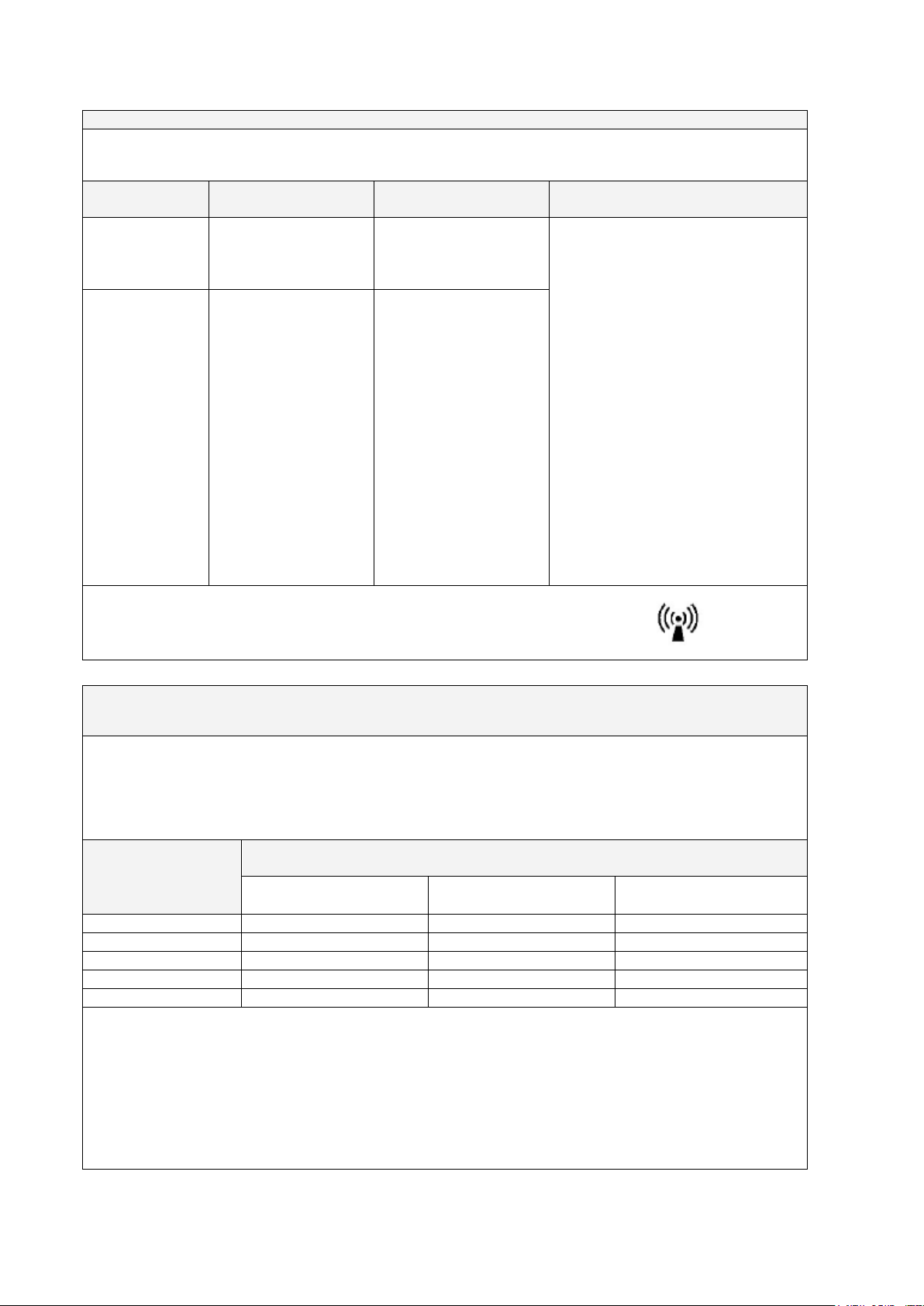
Emission Guidance
The CC-100 SERIE is intended for use in the electromagnetic environment specified below. The costumer or the
user of the CC-100 SERIE should assure that it is used in such an environment.
Emission Test
Compliance
Electromagnetic enviroment guide
RF Emission
Cispr 11
Group 1
The CC-100 SERIE device uses RF energy only for
its internal function. Therefore, its RF emissions
are very low and are not likely to cause any
interference in nearby electronic equipment.
RF Emission
Cispr 11
Class B
The CC-100 SERIE device is suitable for use in all
establishments, except for domestic
establishments and those directly connected to
the public low-voltage power supply network that
supplies buildings used to domestic purposes.
It is possible to use the device in all
establishments, including domestic
establishments and those directly connected to
the public low-voltage power supply network that
supplies buildings used for domestic purposes.
Harmonic Emission
IEC 61000-3-2
Class A
Compliant
It is possible to use the device in all
establishments, including domestic
establishments and those directly connected to
the public low-voltage power supply network that
supplies buildings used for
domestic purposes
Voltage Fluctuation/flicker
Emission
IEC 61000-3-3
Compliant
5
Page 6

Immunity Guidance
The CC-100 SERIE device is intended for use in the electromagnetic environment specified below. The
customer or the user of the device should assure that it is used in such an environment.
Immunity Test
Test level
EN 60601-1-2
Conformity Level
Electromagnetic
enviroment guide
Electrostatic Discharge (ESD)
EN 61000-4-2
8kV air
6kV contact
8kV air
6kV contact
Floors should be wood,
concrete or ceramic tile. If
floors are covered with
synthetic material, the
relative humidity should be at
least 30 %.
Electrical Fast Transient/Burst
EN 601000-4-4
±2 kV high voltage
power line
±2 kV high voltage
power line
Mains power quality should
be that of a typical
commercial or hospital
environment.
Surge EN 61000-4-5
Differential mode:
1 kV
Common mode:
2kV
Differential mode:
1 kV
Common mode:
2kV
Mains power quality should
be that of a typical
commercial or hospital
environment.
Voltage dips, short
interruptions and voltage
variations on power supply
input lines
EN 61000-4-11
<5% UT
(>95% dip of UT)
for 0,5 cycle
40% UT
(>60% dip of UT)
for 5 cycle
70% UT
(>30% dip of UT)
for 25 cycle
<5% UT
(>95% dip of UT)
for 5 seconds
<5% UT
(>95% dip of UT)
for 0,5 cycle
40% UT
(>60% dip of UT)
for 5 cycle
70% UT
(>30% dip of UT)
for 25 cycle
<5% UT
(>95% dip of UT)
for 5 seconds
Mains power quality should
be that of a typical
commercial or hospital
environment. If the user of
the device requires continued
operation during power
mains interruptions, it is
recommended that the
device be powered from an
uninterruptible power supply
or a battery.
Magnetic field at power
frequency
EN 61000-4-8
3 A /m
3 A /m
Magnetic power frequency
fields
should be that of a typical
commercial or hospital
environment.
6
Page 7
Immunity Radio Frequency Guidance
The CC-100 SERIE is manufactured to work in the electromagnetic environment specified below. The
operator or user should make sure it is use within those environmental conditions..
Immunity Test
Test level
EN 60601-1-2
Conformity Level
Electromagnetic enviroment
guide
Conducted RF
EN 61000-4-6
3 Veff from 150kHz to
80MHz
3 Veff from 150kHz to
80MHz
Portable and mobile RF
communications equipment should
be used no closer to any part of the
device, including cables, than the
recommended separation distance
calculated from that equation
applicable to the frequency of the
transmitter.
Recommended separation distance
d = 1,2 ⋅√P from 150kHz to 80MHz
d = 1,2 ⋅√P from 80 MHz to 800
MHz
d = 2,3 ⋅√P from 800 MHz to 2,5
GHz
where P is the maximum output
power rating of the transmitter in
watts (W) according to the
transmitter manufacturer and d is
the recommended separation
distance in meters (m)
Radiated RF
EN 61000-4-3
3 V/m from 80MHz to
2.5GHz
3 V/m from 80MHz to
2.5GHz
The field intensity of the fixed RF transmitters, as checked in an
electromagnetic investigation of the locus, should be less than the
conformity level for each range of frequency. It is possible to have
interference near devices marked with the symbol:
Recommended separation distances between portable and mobile RF communications
equipment and the CC-100 XP device
CC-100 SERIE device is intended for use in an electromagnetic environment in which radiated RF
disturbances are controlled. The customer or the user of the device can help prevent electromagnetic
interference by maintaining a minimum distance between portable and mobile RF communications
equipment (transmitters) and the device as recommended below, according to the maximum output
power of the communications equipment.
Output maximum
nominal power of
the transmitter (W)
Separation distance at the transmitter frequency (m)
from 150kHz to 80MHz
D= 1,2 x P
from 80MHz to 800MHz
D= 1,2 x P
from 800MHz to 2GHz
D= 2,3 x P
0,01
0,12
0,12
0,23
0,1
0,38
0,38
0,73
1
1,2
1,2
2,3
10
3,8
3,8
7,3
100
12
12
23
For transmitters rated at a maximum output power not listed above, the recommended separation
distance d in metres (m) can be determined using the equation applicable to the frequency of the
transmitter, where P is the maximum output power rating of the transmitter in watts (W) according to the
transmitter manufacturer.
Notes:
(1) At 80 MHz and 800 MHz, the separation distance for the higher frequency range applies.
(2) These guidelines may not apply in all situations. Electromagnetic propagation is affected by
absorption and reflection from structures, objects and people.
7
Page 8
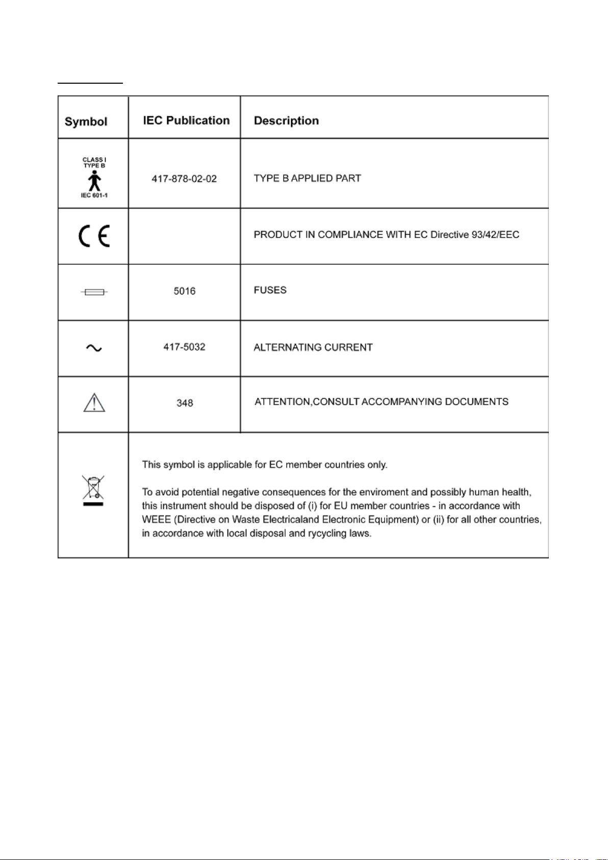
Symbol Table:
8
Page 9
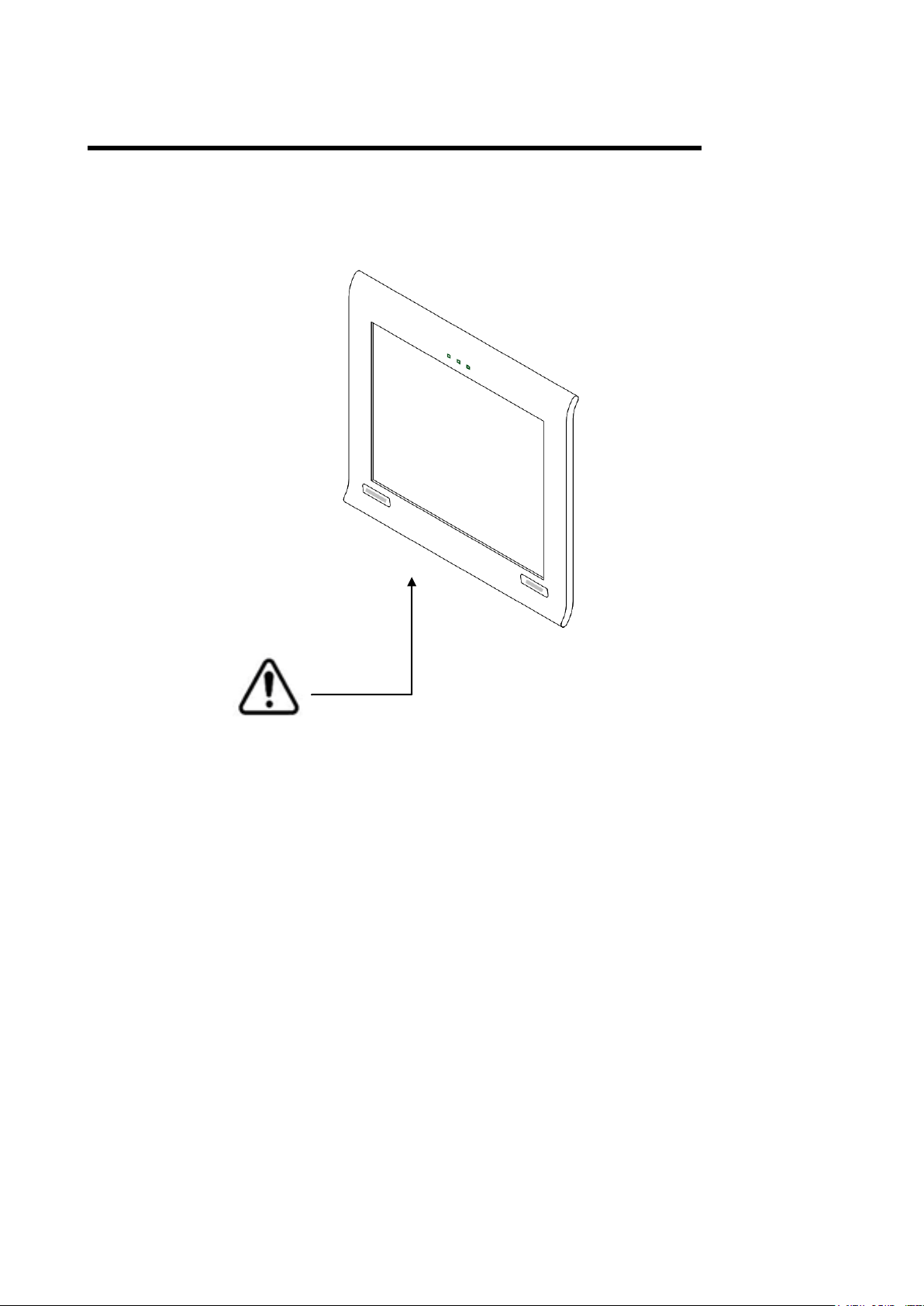
WARNING INDICATIONS AND POSITIONS
For safety purposes, this equipment includes clearly labelled warnings.
Use the equipment following this warning instructions.
CAUTION
To avoid electrical shock, do not open the instrument. Refer all servicing to only qualified personnel.
WARNING
Electrical shock may cause burns or possible fire. Turn the main power switch OFF and UNPLUG the power
cord before replacing fuses. Replace only with fuses of the correct rating.
9
Page 10
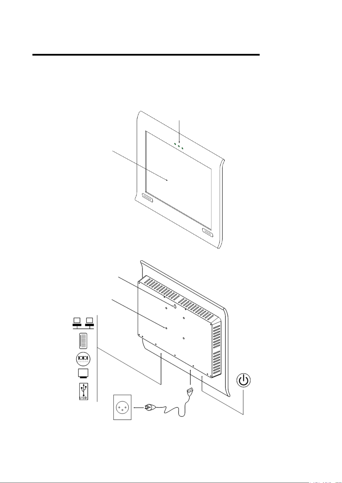
COMPONENTS
I/R Sensor
Photo Sensor
Maddox Led
Test Area
Wall hook
Wallmounting
screw holes
AC-3 pin
Power cable
MAIN BODY COMPONENTS
10
Page 11
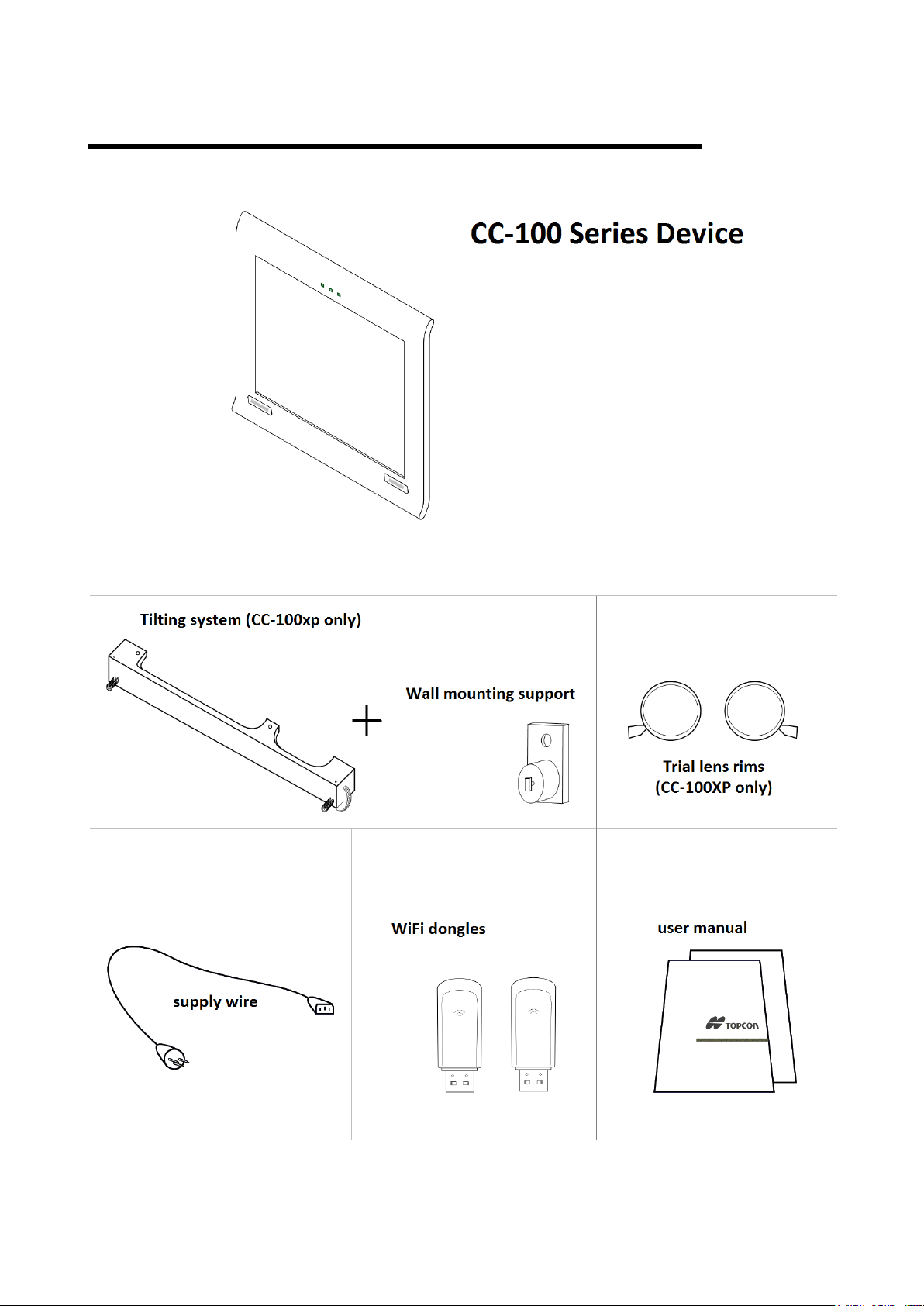
CC-100 SERIES STANDARD ACCESSORIES
11
Page 12
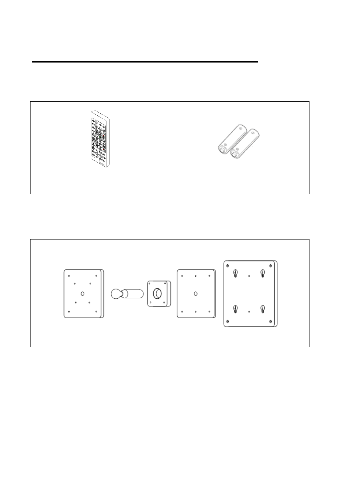
Remote Control
(only for CC-100 Series instruments)
CC-Series Remote Control Batteries
(AAA Type)
CC-SERIES OPTIONAL ACCESSESORIES
REMOTE CONTROL
CC-100 WALL MOUNTING
12
Page 13
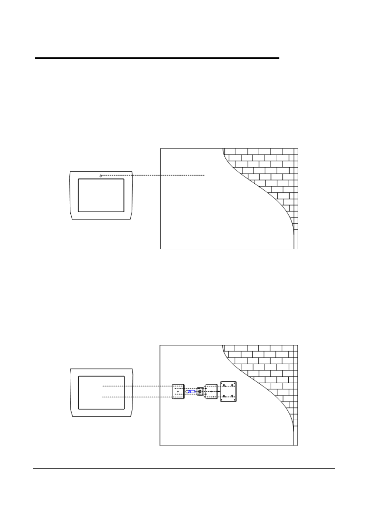
PREPARATIONS
Without WALL MOUNTING
With WALL MOUNTING
WARNING: use appropriate screws and plugs to fix the unit to the wall.
13
Page 14

SWITCH BETWEEN LCD Chart Projector and CV-tablet
When using the new CC-100 Series device, we will find pre-installed two main charts software. The
LCD Chart Projector and of course the CV-tablet.
To use one instead of the other follow the steps below directly on the CC-100:
1- First of all connect an external
mouse to the CC-100, now to exit
the application click two times on
the left button, if on the LCD
Chart Projector, or just a click if
on the CV-tablet
2- Click on the start button
3- Launch the CC Series and CV
tablet switcher
4- Choose the desired application
clicking on the proper button:
14
Page 15

BASIC OPERATIONS
1 Infrared led
2 Mode selection
3 Visual Acuity selection
4 Mask and red-green filter functions
5 Random
6 Contrast
7 Inverted
8 Fixation point / Amsler’s grid,
Schober test / Worth test
9 Bichromatic vision tests and
Polarized stereo tests (CC-100XP)
Bichromatic vision tests and RG
stereo tests (CC-100)
10 ETDRS
11 Astigmatism Tests (clock, grid, dots)
12 Contrast sensitivity test / SineWave
contrast sensitivity test
13 Pseudoisochromatic test
14 Fixation charts
15 Arrows navigational cursor direction
16 Menu (second function: exit from
special test)
17 Light (second function: no answer in
the special tests)
18 MKH sequence
19 Stereo Right / Left eye inversion
1 2 3
4 6 5 7 8
10
9
11
12
13
14
16
17
15
18
19
REMOTE CONTROL (CC-100 SERIES MODE )
15
Page 16

VISUALIZATION OF A SPECIFIC SCREEN SHOT
Letters
Snellen E
Landolt C
Numbers
Drawings for Children
Select symbols
16
Page 17

Select Visual Acuity levels
ETDRS
Only the first two buttons of section can be used.
17
Page 18

Masking by line, column or single cell and red-green background
Vertical Mask
Horizontal Mask
Single Cell Mask
R/G Background
Casual chart generating (random function)
To deactivate the function press the button again.
Contrast modifying of “chart over background”
Pressing the arrow buttons on the remote control the type contrast change with step 0.1.
To deactivate the function press the button again.
18
Page 19

Inversion
OFF
ON
If fixation led option
is set to ON
(see Menu section
on this manual).
To deactivate the function press the button again.
Fixation point, Amsler’s grid, Worth test and Schober test
19
Page 20

CC-100: Bichromatic monocular tests
CC-100XP: Polarized balance test (see Note 1)
NOTE 1 (for CC-100XP only)
The drawings are only exemplificative. Red parts are seen by the right eye, green parts are seen by
the left eye. The charts are all black on white.
20
Page 21

Dissociated tests
CC-100: Red/Green filter
CC-100XP: Left/Right circular polarization (see Note 1)
21
Page 22

Unpolarized tests
22
Page 23

SPECIAL TESTS
Choose Chart Type
Choose Visual Acuity Level
Start Test
Contrast Sensitivity Test
(First press)
Use the arrow buttons for the test. The least difference of contrast distinguished from the patient is displayed
on the screen.
23
Page 24

Sinewave Contrast Sensitivity
Choose Test Map
Map Settings
Start Test
(Second press)
Map patterns and settings
Enter into Map Settings sub menu to change options for selected Test Map.
24
Page 25

Each Test Map has a pattern you can edit from Edit Map function.
Test Map
Contrast levels
Frequency levels
Map 1
5 4 Map 2
8 5 Map 3
9
9
Displayed image
Arrow button to
press
Use the arrow buttons for the test, the "none" key (17) must be pressed for no answer
25
Page 26

A graph will be visualized. The area of normality is underlined in green.
26
Page 27
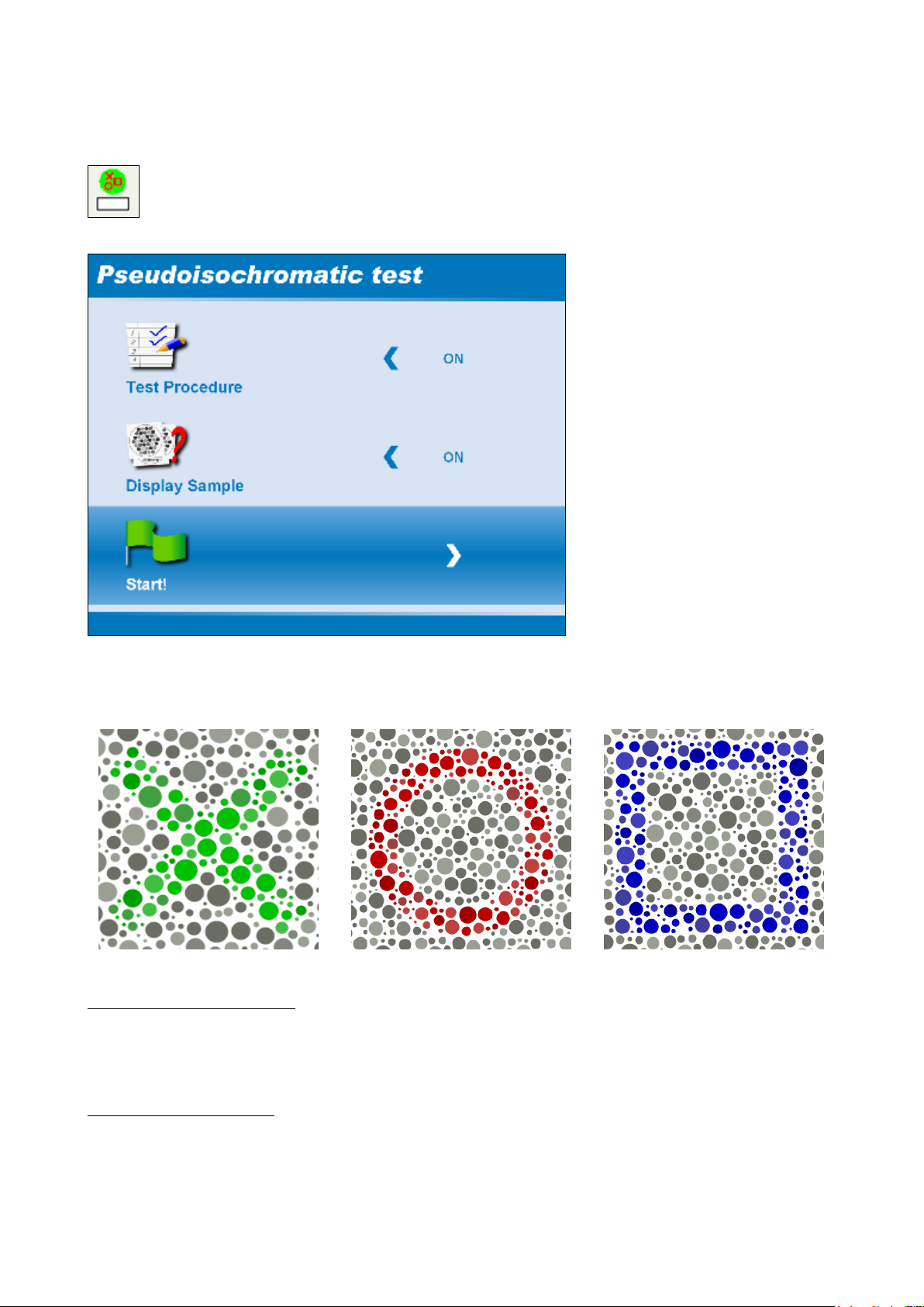
Pseudoisochromatic Test
Test Procedure (ON/OFF)
Sample plates (ON/OFF)
Start Test
Ask the patient to recognize three different symbols hidden between dots.
Testing without test procedure
Use right arrow button to go to the next plate. Use left button to go to the previous plate.
Up and down arrow plate change the symbol inside the same plate.
Testing with test procedure
Ask the patient to recognize the position of the symbol (not the symbol itself) inside the screen. Use the
diagonal arrow button to match patient's answers.
27
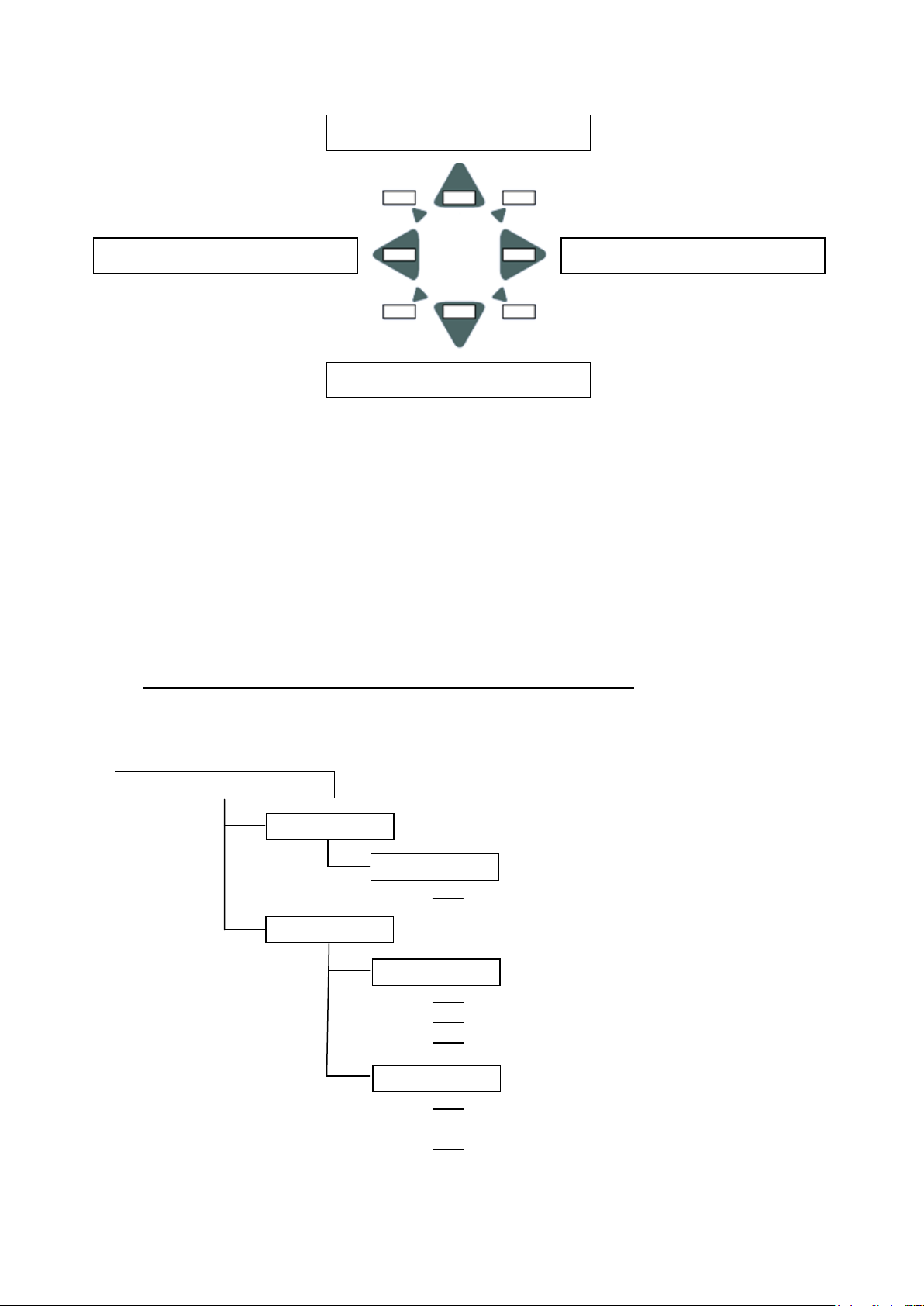
Page 28

Symbol in upper left position
Symbol in upper right position
Symbol in bottom left position
Symbol in bottom right position
At the end of the test with test procedure a table will be presented.
28
Page 29

FIXATION TARGETS
Use this menu item to refresh the
group list, adding groups archived
on USB.
…
Next image in sequence
Previous image in sequence
Images and movies are located into 4 different groups.
If you use the USB archive too, also the groups stored in the USB pendrive are shown.
Images
Display images to use as fixation targets.
Use arrows to select image.
29
Page 30

Movies
Play the movies.
Use arrows to manage movies.
30
Page 31
Previous movie
Next movie
Replay / Go back
Continue / Go ahead
USB pen drive root ( \ )
images
various
group 2
1.jpg
2.jpg
.....
a.avi
b.avi
.....
movies
group 1
1.swf
2.swf
.....
How to configure the USB pen drive to archive additional images and/or movies
Format USB pen drive in FAT32 file system format
In the device root, create a folder called “images”
Into the “images” folder, copy your image files (in JPG format) under some sub-folders (the name
can be set by the user)
In the device root, create a folder called “movies”
Into the “movies” folder, copy your movie files (in SWF, AVI format) under some sub-folders (the
name can be set by the user)
N.B.: inside each sub-folder, all the movies must be of the same format!
An example of how to configure an USB pen drive is shown below.
31
Page 32

MKH SEQUENCE
Next chart in sequence
Previous chart in sequence
(see Note 1)
Use arrows to select chart.
Use R/L button to swap right and left eye.
32
Page 33

LIGHT
Screen illumination.
MENU
General Settings
Language
Language selection.
33
Page 34

Kids Chart Types (CC-100 Series / KB-50)
Chart A
Chart B1
Chart C
OFF
ON
Distance
Distance patient-display.
Mirror
34
Page 35

Progression
Decimal
LogMAR or ISO8596
Measurement Units
Notation for Visual Acuity: Decimal, Monoyer, Snellen (m), Snellen (Ft), or LogMAR.
Acuity Value Display
Possible settings: ON, ON/OFF, ON/OFF big fonts, OFF.
I/R Devices
Select a working mode for each of the 4 channels.
Serial Device
Connect the Topcon CV-5000 by serial connector. For the COM port baud rate, see the Technical Settings.
VA Background Regulation
Regulate the brightness of the background
35
Page 36

Red Level Regulation
Set the red tone parameter of the screen to be used with the red-green filter.
Green Level Regulation
Sets the green tone parameter of the screen to be used with the red-green filter.
Light Sensor
Determine if the environment illumination is correct.
Fixation Led
Enable or disable the fixation led when using Maddox test.
Select Printer
Select the default printer.
Technical Settings
Access to the administrator area.
36
Page 37

Technical Settings
Upgrade
To upgrade the CC-100 Series Device software you will receive a compressed zip file. It contains only 2 files:
Upgrade.exe
a big file with extension .UPG; its name tells you the version of that upgrade (for example: CC-100
3.3.1.UPG or CC-100XP 3.3.1.UPG)
To upgrade the CC-100 Series Device software do the following things:
1. Unpack the zip file in a blank, FAT32 formatted, USB pen drive
2. Plug the pen drive in a USB port of the CC-100 Series Device
3. In the CC-100 Series Device go to Menu and select Technical Settings, and then Upgrade
the message “Copying new files. Please wait...” appears for a moment
the message “Remove the USB pen drive. The system will now restart.” appears
the system reboots for the first time (this may take a while)
4. When the system boots up, the upgrade process will start automatically
5. At the end of the upgrade process, the system will reboot for the second time
6. Finally, after the boot, the upgrade is done, and the system is ready to use.
The upgrade procedure needs the system has to be rebooted two times, but the entire process is very easy
from the user side.
In addiction, the upgrade procedure integrates some checks to prevent the updating of wrong systems: so,
only systems with hardware 2.0 can be updated, and only the same system type (CC-100 upgrade over a
CC-100, and CC-100XP upgrade over a CC-100XP).
Screensaver
Screensaver settings.
37
Page 38

Configure Network
Network settings. ONLY FOR SPECIFIED MODELS.
Serial COM port baud rate
Serial COM port baud rate setting.
Settings: Reset to Default
Reset to default settings.
Exit
It terminates the software.
38
Page 39

CONFIGURE NETWORK
ONLY FOR SPECIFIED MODELS.
“Standalone” Mode
Use the device as stand-alone. No network use.
“Network” Mode
Use the device as part of a network (PC).
The system configures the network automatically.
39
Page 40

Server search (PC with communication software installed).
Server selection.
40
Page 41

MAINTENANCE
Power supply voltage
Fuse’s type
Fuse’s value
220 – 240 V
20 x 5 mm
2.5 A 250 V antisurge
Fuse change of the CC-100 Series
Make sure that the power switch of the main body is off and the power cable is unplugged.
Fuse’s types
Page 42

42
Battery change of the CC-100 Series remote control
Channel
Channel Switches
1
S1 = H
S2 = H
2
S1 = L
S2 = H
3
S1 = H
S2 = L
4
S1 = L
S2 = L
Channel switch position on the remote control
Channel switch
Remove the battery cover, insert new 1.5V batteries (type AA) and replace the cover.
Change of the channel setting of CC-100 Series remote control
Remove the battery cover from the back of the remote control.
Set the remote control channel following the table below:
 Loading...