

Page 1
INSTRUCTIONS FOR USE
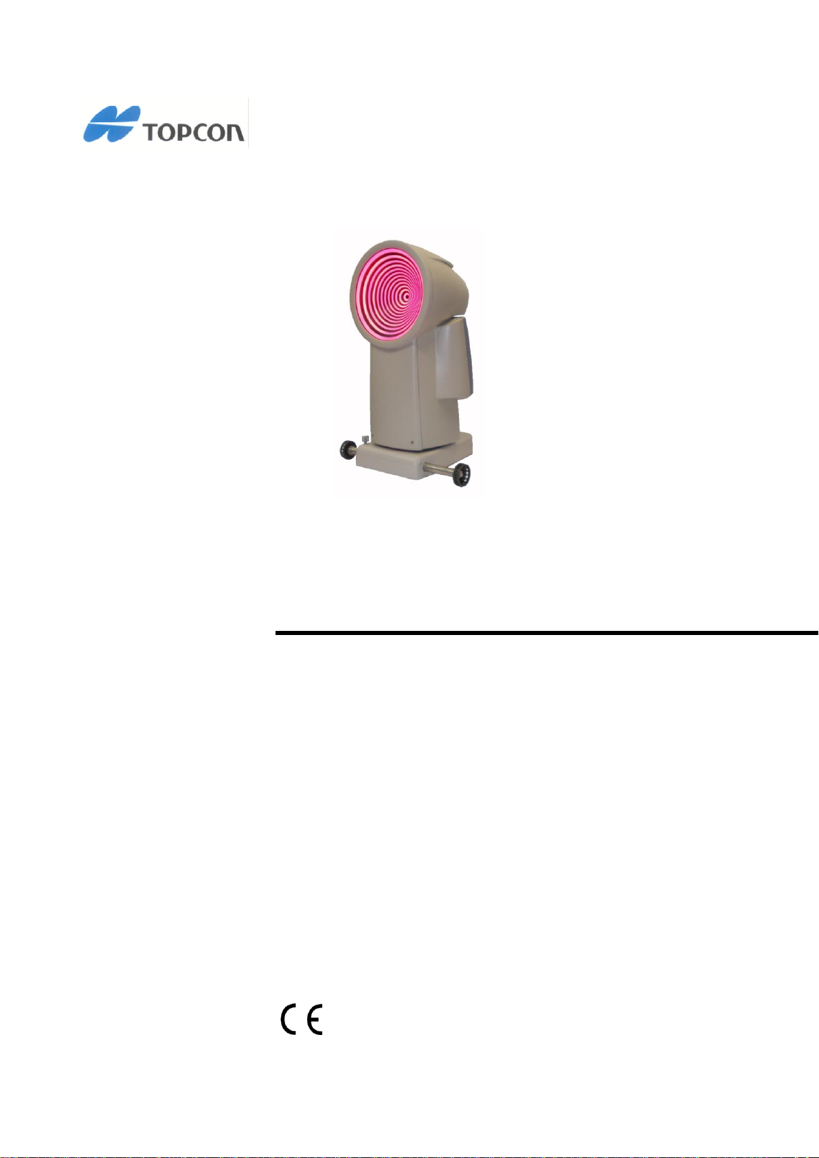
CORNEAL ANALYSER
CA-200F CORNEAL ANALYSER
0051 REV. 7 2012
Page 2

CA-200F Corneal Analyser - Rev. 7 16/01/2012
NOTES
Installation with external devices
The CA-200F corneal analyser complies with the CE marking requirements.
Before connecting an external device (computer, printer, display, keyboard, mouse, slit lamp), check that
these devices are in compliance with the EN 60950-1 standards and bear the CE marking.
If the CA-200F corneal analyser is installed in rooms for medical use, any connected personal computer and
printer must be powered by an insulated transformer in accordance with IEC 60601-1.
If the CA-200F corneal analyser is installed in rooms for medical use and is not connected to a computer,
there is no need to use an insulated transformer. If a printer is connected directly to the CA-200F corneal
analyser, it must be powered by an insulated transformer in accordance with IEC 60601-1.
In the event of an accident or near accident due to use of the instrument, please contact:
Manufacturer
VISIA imaging S.r.l.
Via C. E. Gadda, 15
52027 San Giovanni Valdarno (AR)
Italy
In the event of a fault or to request technical service, contact:
Distributor
TOPCON EUROPE MEDICAL B.V.
Essebaan 11
2908 LJ Cappelle A/D Ijseel
THE NETHERLANDS
WARNING
The CA-200F device must be used with the power supply provided in the package
and in any case only with an EXM 80 5118 power supply for medical use.
2
Page 3

CA-200F Corneal Analyser - Rev. 7 16/01/2012
INTENDED USE
Use:
CA-200F is a corneal analyser with integrated pupillograph.
The instrument acquires images of the cornea and analyses its topography.
The software selects the image with the best focus out of a sequence of images.
In the image, the rings of the disc reflected by the illuminated cone are used to geometrically calculate the
topographic map of the cornea. From the topographic map data, a set of parameter indices are processed
for the measurements.
The main applications of the corneal analyser are the following:
Cornea measurements for diagnostic instruments
Cornea and pupil measurements for application of contact lenses
Fluorescence analysis for contact lens positioning
Pupil measurements for the determination of specific pathologies
Users:
Eye specialists, ophthalmologists, opticians, optometrists.
The instrument must be used by qualified persons.
Facilities:
Health centers, optician shops, eye hospitals and other eye-care related facilities.
3
Page 4

CA-200F Corneal Analyser - Rev. 7 16/01/2012
INTRODUCTION
Thank you for purchasing the TOPCON CA-200F Corneal Analyser.
The intuitive and user-friendly software interface and the hardware, designed for patient comfort, make the
CA-200F one of the most popular corneal analysers on the market.
The instrument analyzes any type of corneal map: axial, instantaneous with 2D representation.
This instrument also allows you to simulate contact lenses and view the 3D map to analyze the wavefront
corneal aberrations.
Notes:
This manual describes the TOPCON CA-200F corneal analyser, including the functions, basic operations,
instrument cleaning, and instrument storage.
For best use of the instrument, carefully read the instructions provided.
Keep these instructions in a safe place.
4
Page 5

CA-200F Corneal Analyser - Rev. 7 16/01/2012
Emission aspects
The CA-200F device is intended for use in the electromagnetic environment specified below. The
customer or the user of the device should ensure that it is used in the said environment.
Emission test
Compliance
Electromagnetic environment – guidance
RF emissions
CISPR 11
Group 1
The CA-200F device uses RF energy only for its internal function.
Therefore, its RF emissions are very low and are not likely to cause
any interference in nearby electronic equipment.
RF emissions
CISPR 11
Class B
The CA-200F device is suitable for use in all establishments,
including domestic establishments and those directly connected to
the public low-voltage power supply network that supplies buildings
used for domestic purposes.
Harmonic emissions
IEC 61000-3:2
Class A
Compliant
The device can be used in all buildings, including domestic buildings
and those directly connected to the public low-voltage power supply
network, that supplies buildings used for domestic purposes.
Voltage fluctuations/
flicker emissions
IEC 61000-3:3
Compliant
PRECAUTIONS
This electronic instrument is a precision unit. Use and store it in a suitable place in normal temperature,
humidity and atmospheric pressure conditions and avoid exposure to direct sunlight.
To ensure proper functioning, install the instrument in a place not subject to vibrations.
Connect all the cables correctly before use.
Use the recommended mains voltage.
When the unit is not used, disconnect the power supply and protect it against the sun and dust.
In order to obtain accurate and reliable measurements, keep the measuring cone clean and dust-free.
This product is in compliance with the EMC standards (IEC 60601-1-2:2001).
- ELECTROMEDICAL DEVICES require particular precautions for electromagnetic compatibility and
must be installed and set up based on the EMC information provided in the accompanying
documents.
- Portable RF communication instruments may interfere with medical devices.
- Using accessories and cables different from those provided with the instrument, except for the
cables sold by the equipment manufacturer as spare parts, may result in increased emissions and
reduce the immunity of the device or system.
- The device must not be used in contact with other equipment.
If it is inevitable to use the device in contact with other instruments, check proper functioning in the
required configuration.
EMC table
5
Page 6
CA-200F Corneal Analyser - Rev. 7 16/01/2012
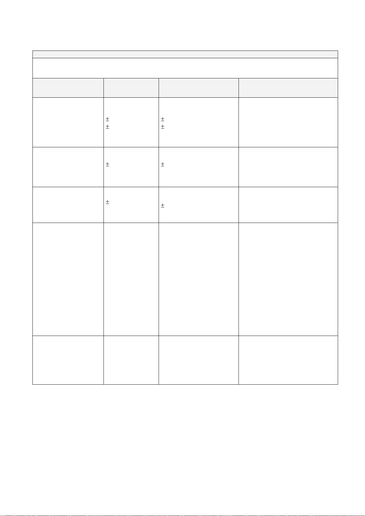
Immunity aspects
The CA-200F device is intended for use in the electromagnetic environment specified below. The
customer or the user of the CA-200F device should assure that it is used in the said environment.
Immunity test
EN 60601-1-2
test level
Compliance level
Electromagnetic environment –
guidance
Electrostatic discharge
(ESD)
EN 61000-4-2
6kV contact
8kV air
6kV contact
8kV air
Floors should be made of wood,
concrete or ceramic tiles. If floors
are covered with synthetic
material, the relative humidity
should be at least 30%
Electrical fast transient/
burst
EN 61000-4-4
2kV for power
supply lines
2kV for
power supply lines
The quality of the power mains
should be that of a typical
commercial or hospital
environment.
Surge
EN 61000-4-5
1kV differential
mode
1kV differential mode
The quality of the power mains
should be that of a typical
commercial or hospital
environment.
Voltage dips, short
interruptions and
voltage variations on
power supply input lines
EN 61000-4-11
< 5% U
T
(>95% dip in UT)
for 0.5 cycle
40% U T
(60% dip in UT)
for 5 cycle
70% U T
(30% dip in UT)
for 25 cycle
< 5% U T
(>95% dip in UT)
for 5 seconds
< 5% U T
(>95% dip in UT)
for 0.5 cycle
40% U
T
(60% dip in UT)
for 5 cycle
70% U T
(30% dip in UT)
for 25 cycle
< 5% U T
(>95% dip in UT)
for 5 seconds
The quality of the power mains
should be that of a typical
commercial or hospital
environment. If the user requires
continuous device operation
during power mains interruptions,
it is recommended that the device
be powered using an
uninterruptible power supply or a
battery.
Power frequency
magnetic field
EN 61000-4-8
3 A/m
3 A/m
Power frequency magnetic fields
should be at levels characteristic
of a typical location in a typical
commercial or hospital
environment.
6
Page 7
CA-200F Corneal Analyser - Rev. 7 16/01/2012
Radio frequency immunity aspects
The CA-200F device is intended for use in the electromagnetic environment specified below. The
customer or the user of the CA-200F device should assure that it is used in the said environment.
Immunity test
EN 60601-1-2 test
level
Compliance level
Electromagnetic environment –
guidance
Conducted RF
EN 61000-4-6
3 V from 150kHz to
80MHz
3 V from 150kHz to
80MHz
Portable and mobile
RF communications equipment should not
be used in the vicinity of the device,
including its cables,
unless the recommended
separation distance
calculated from the
equation applicable to the frequency of the
transmitter is observed.
Recommended separation distance
d = 1.2 P from 150kHz to 80MHz
d = 1.2 P from 80 MHz to 800 MHz
d = 2.3 P from 800 MHz to 2.5 GHz
where P is the maximum output power rating of
the transmitter in watts (W) according to the
transmitter manufacturer
and d is the recommended separation distance
in meters
( m ).
Radiated RF
EN 61000-4-3
3 V from 80MHz to
2.5GHz
3 V from 80MHz to
2.5GHz
The fixed RF transmitter field strength, as determined by an electromagnetic site survey,
may be lower than the compliance level in relation to each frequency range.
Interference may occur in the vicinity of equipment marked with the following symbol:
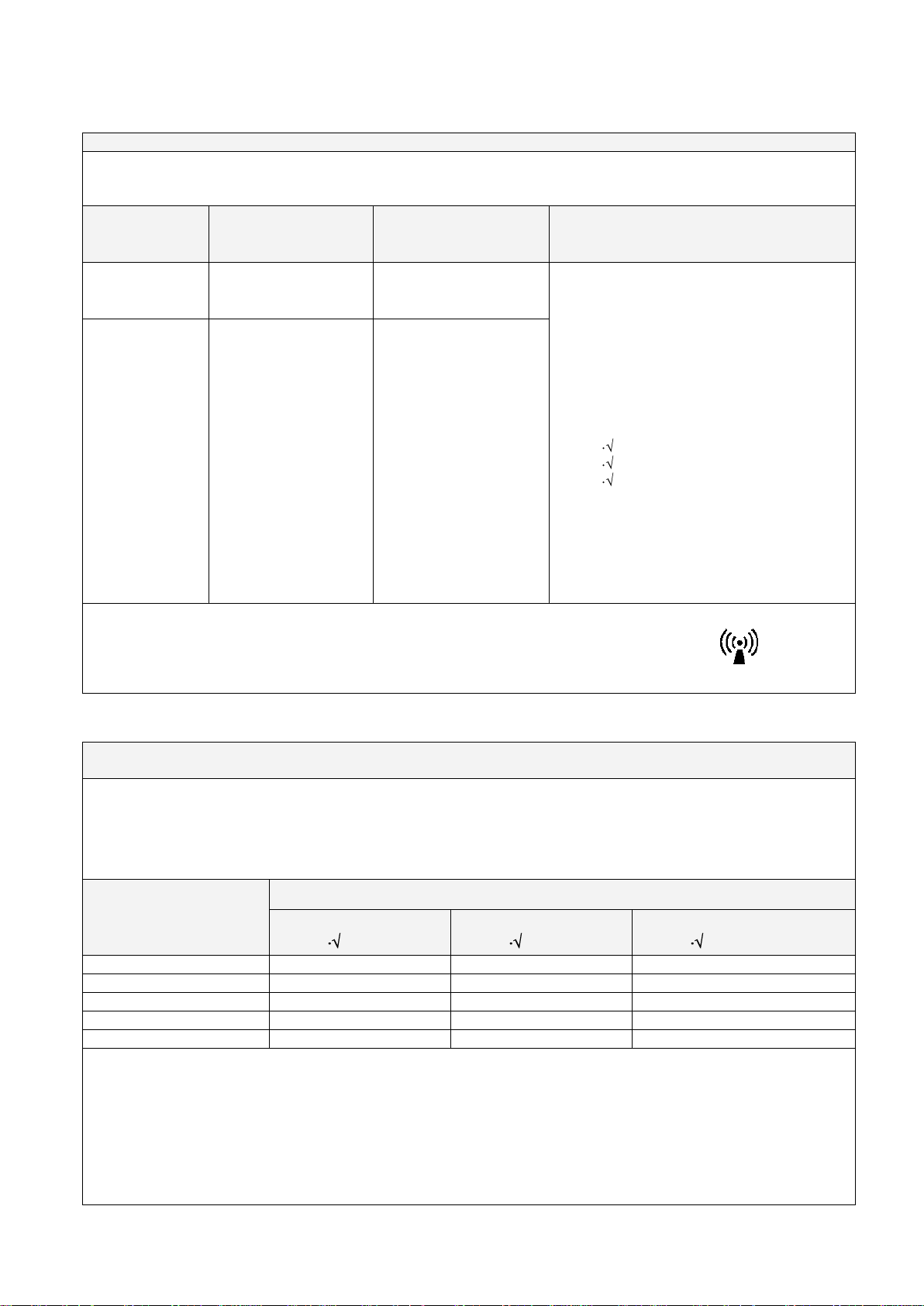
Recommended separation distances between portable and mobile RF communications equipment and
the surgical Navigation device
The CA-200F device is intended for use in an electromagnetic environment in which radiated RF disturbances are
controlled. The customer or the user of device can help prevent electromagnetic interference by maintaining a
minimum distance between portable and mobile RF communications equipment (transmitters) and the device as
recommended below, according to the maximum output power of the communications equipment.
Rated maximum output
of transmitter (W)
Separation distance according to frequency of transmitter (m)
150kHz to 80MHz
d = 1.2 P
80MHz to 800MHz
d = 1.2 P
800MHz to 2GHz
d = 2.3 P
0.01
0.12
0.12
0.23
0.1
0.38
0.38
0.73
1
1.2
1.2
2.3
10
3.8
3.8
7.3
100
12
12
23
For transmitters rated at a maximum output power not listed above the recommended separation distance d in meters (m)
can be estimated using the equation applicable to the frequency of the transmitter, where P is the maximum output power
rating of the transmitter in watts (W) according to the transmitter manufacturer.
Note:
(1) At 80 MHz and 800 MHz, the separation distance for the higher frequency range applies
(2) These guidelines may not apply in all situations. Electromagnetic propagation is affected by absorption and reflection
from structures, objects and people.
7
Page 8
CA-200F Corneal Analyser - Rev. 7 16/01/2012
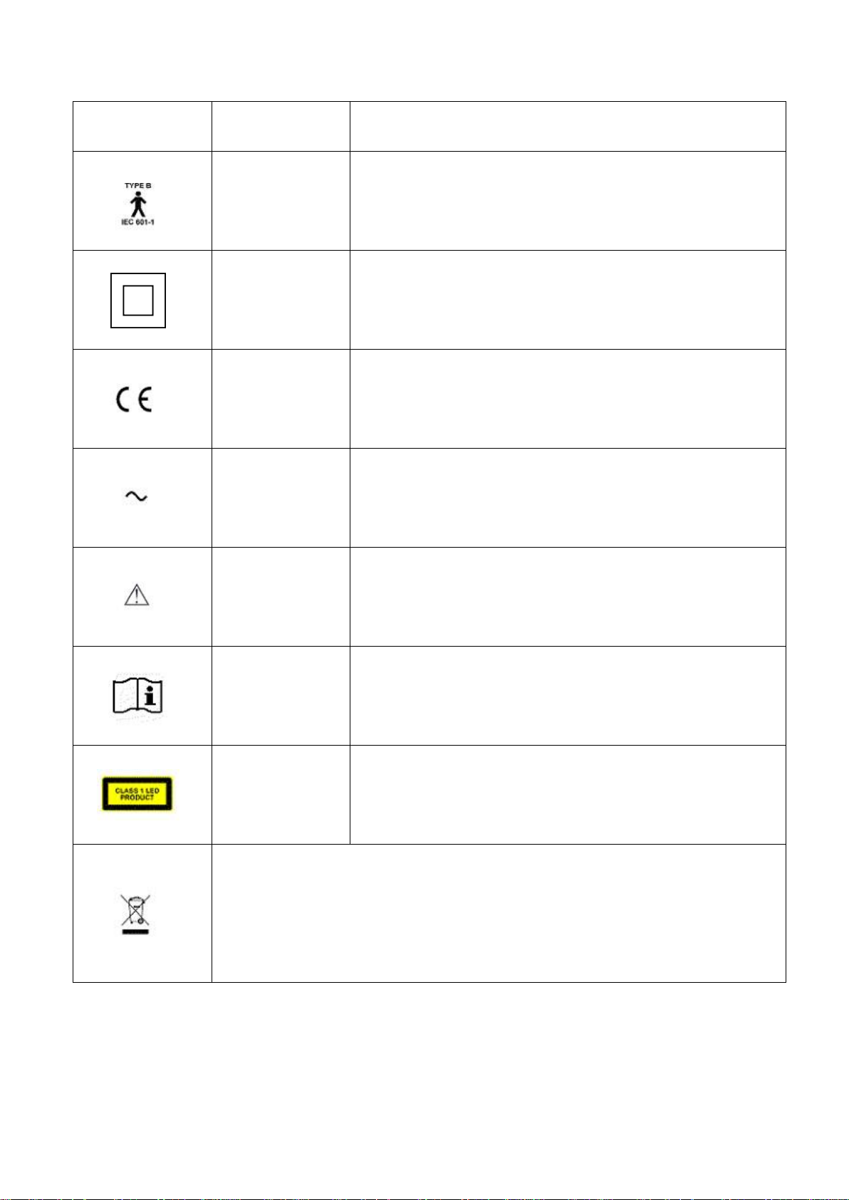
Symbols
IEC
publications
Description
IEC 60417-5840
CLASS II DEVICE IN ACCORDANCE WITH 60601-1
APPLIED PART TYPE B
IEC 60417-5172
INSULATION CLASS II DEVICE (DOUBLE INSULATION)
PRODUCT IN ACCORDANCE WITH DIRECTIVE 93/42/EEC
IEC 60417-5032
ALTERNATING CURRENT
ISO 7000-0434A
WARNING, CONSULT THE ATTACHED DOCUMENTATION
ISO 7000-1641
OPERATING INSTRUCTIONS
CLASS 1 LED PRODUCT IN ACCORDANCE WITH EN 60825-1
This symbol applies solely to EU member states.
With the aim of preventing potential negative consequences for the environment and
possibly human health, this instrument must be disposed of (i) in compliance with the
WEEE (Waste Electrical and Electronic Equipment) Directive for member states of the
EU, or (ii) in compliance with the local recycling regulations and laws for all other
countries.
8
Page 9

CA-200F Corneal Analyser - Rev. 7 16/01/2012
WARNINGS FOR SAFE USE
In order to safely use the instrument and prevent risks to the operator and other persons as well as damage
to the device, the instruction manual provides a description of the safety warning labels and plates on the
instrument body.
Carefully read the following PRECAUTIONS and SAFETY RULES as well as the manual and observe the
instructions contained therein.
WARNINGS
Improper use of the instrument ignoring this warning may result in death or serious injury.
Improper use of the instrument ignoring this warning may result in personal injury or physical damage.
9
Page 10

CA-200F Corneal Analyser - Rev. 7 16/01/2012
USE AND MAINTENANCE
USE
As the CA-200F Corneal Analyser is an electronic instrument for medical purposes, it must be used by
expert and qualified staff.
MAINTENANCE
To ensure the safety and performance of the equipment, it is advisable not to perform operations different
from those indicated below. For detailed information, please follow the instructions.
Calibration check
For details see the paragraph “Calibration Check” in the MAINTENANCE section of this manual.
Measuring cone cleaning
For details see the paragraph “Instrument cleaning and maintenance” in the MAINTENANCE section of
this manual.
RESPONSIBILITY
The manufacturer is not responsible for damage caused by fire, earthquakes, actions by third parties and
other accidents, or negligence and abuse of the instrument by the user in unusual conditions.
The manufacturer is not in any way responsible for damages caused by the user or by unavailability of the
device, such as a loss of profits or suspension of business.
The manufacturer is not responsible for damages caused by use of the device for purposes different from
those described in this instruction manual.
The manufacturer is not responsible for the result of the diagnoses performed with this device.
WARRANTY CONDITIONS
The Warranty is valid subject to application of the above mentioned clauses and only on condition that the
instrument is strictly used for the purposes described in this manual. The warranty conditions applied are
those provided for by local legislation.
10
Page 11
CA-200F Corneal Analyser - Rev. 7 16/01/2012
Transformer
WARNING LABELS AND PLATES
In order to safely use the instrument and prevent risks to the operator and other persons as well as damage
to the device, the instruction manual provides a description of safety warning labels and plates on the
instrument body.
Carefully read the following PRECAUTIONS and SAFETY RULES as well as the manual and observe the
instructions contained therein.
WARNING
To prevent potential injury during operations, be careful not to let the patient’s eyes or nose touch the
instrument.
To prevent electric shock, do not open the instrument. Have qualified staff carry out any operation on the
instrument.
11
Page 12

CA-200F Corneal Analyser - Rev. 7 16/01/2012
Contents
NOTES ................................................................................................................................................... 2
WARNING ............................................................................................................................................. 2
INTENDED USE ..................................................................................................................................... 3
INTRODUCTION .................................................................................................................................... 4
PRECAUTIONS ...................................................................................................................................... 5
WARNINGS FOR SAFE USE ................................................................................................................... 9
WARNINGS ........................................................................................................................................... 9
USE AND MAINTENANCE ................................................................................................................... 10
RESPONSIBILITY .................................................................................................................................. 10
WARRANTY CONDITIONS ................................................................................................................... 10
WARNING LABELS AND PLATES ......................................................................................................... 11
COMPONENTS .................................................................................................................................... 13
MAIN COMPONENT PARTS ............................................................................................................ 13
CONTROL PANEL COMPONENTS .................................................................................................... 14
CA-200F STANDARD ACCESSORIES .................................................................................................... 15
INSTALLATION .................................................................................................................................... 16
Hardware installation (point-to-point network configuration) ................................................. 16
Software installation .................................................................................................................. 16
Installation without network connection .................................................................................. 17
Connection to an existing network ............................................................................................ 17
1. BASIC OPERATIONS .................................................................................................................... 18
GENERAL DESCRIPTION .................................................................................................................. 18
ACQUISITION .................................................................................................................................. 18
ACQUISITION WHEN CONNECTED TO A PC ............................................................................... 18
ACQUISITION IN STAND-ALONE MODE ...................................................................................... 27
TOPOGRAPHIC MAP ....................................................................................................................... 29
TOPOGRAPHIC MAP SETTINGS .................................................................................................. 33
FLUORESCEIN ................................................................................................................................. 35
FLUORESCEIN SETTINGS ............................................................................................................. 36
PUPILLOMETRY (optional module) ................................................................................................ 37
PUPILLOMETRY SETTINGS .......................................................................................................... 41
ZERNIKE (included with pupillometry module) ............................................................................. 42
LENSES ............................................................................................................................................ 44
LENS SETTINGS ........................................................................................................................... 48
TORIC IOL (optional module) ......................................................................................................... 50
ADMINISTRATOR TOOLS ................................................................................................................ 53
MODULE UPDATE ....................................................................................................................... 55
2. CA-200F PC-SOFTWARE ............................................................................................................. 56
SOFTWARE INSTALLATION ............................................................................................................. 56
CA-200F PC SOFTWARE SETTINGS ................................................................................................. 56
3. TROUBLESHOOTING ................................................................................................................... 58
4. REFERENCES ............................................................................................................................... 59
5. SPECIFICATIONS ......................................................................................................................... 60
6. MAINTENANCE ........................................................................................................................... 61
Instrument cleaning and maintenance .......................................................................................... 61
Calibration check ............................................................................................................................ 61
12
Page 13
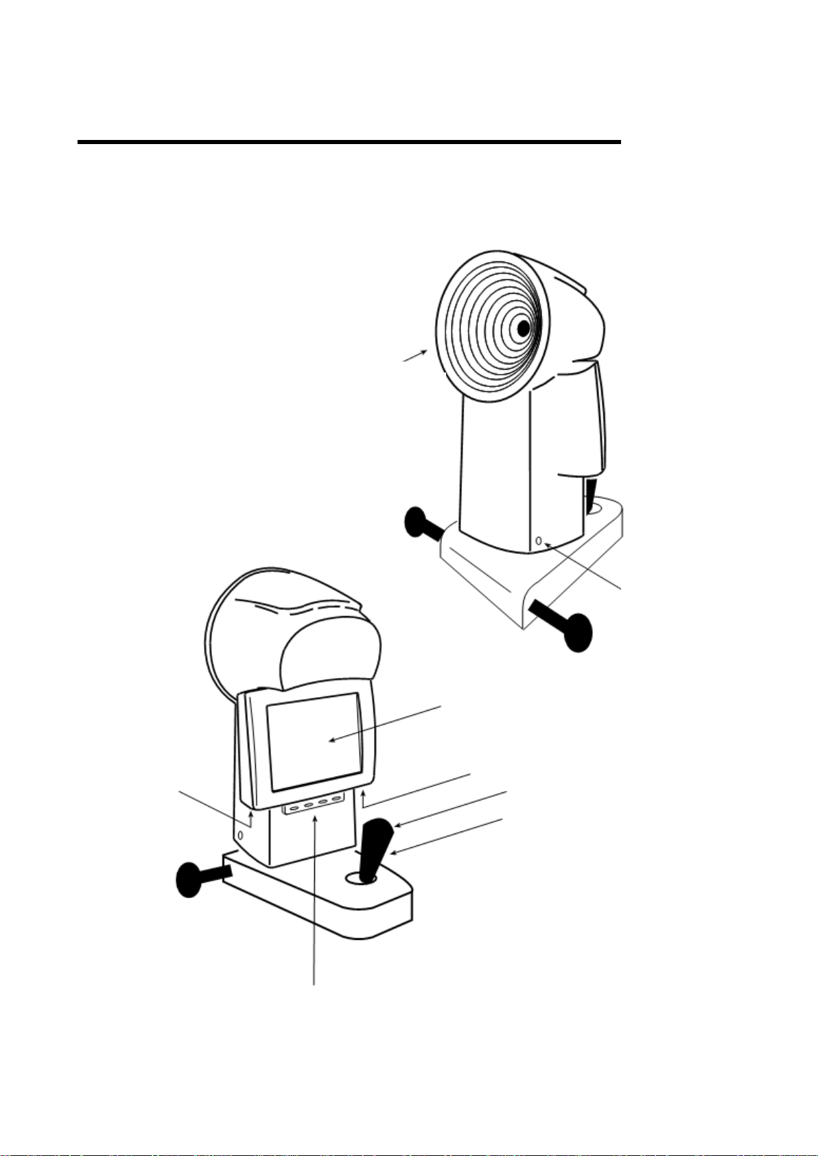
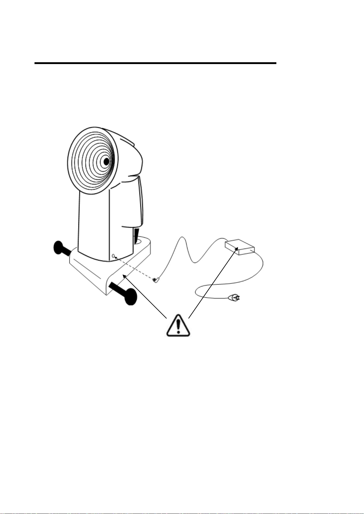
COMPONENTS
Placido disc
Power
connector
Display
USB port
LAN port
Acquisition button
Joystick
Function buttons
ON/OFF
button
MAIN COMPONENT PARTS
CA-200F Corneal Analyser - Rev. 7 16/01/2012
13
Page 14
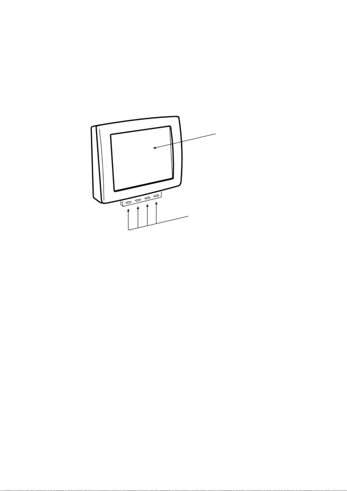
CONTROL PANEL COMPONENTS
Touch screen
display
Function buttons
CA-200F Corneal Analyser - Rev. 7 16/01/2012
14
Page 15
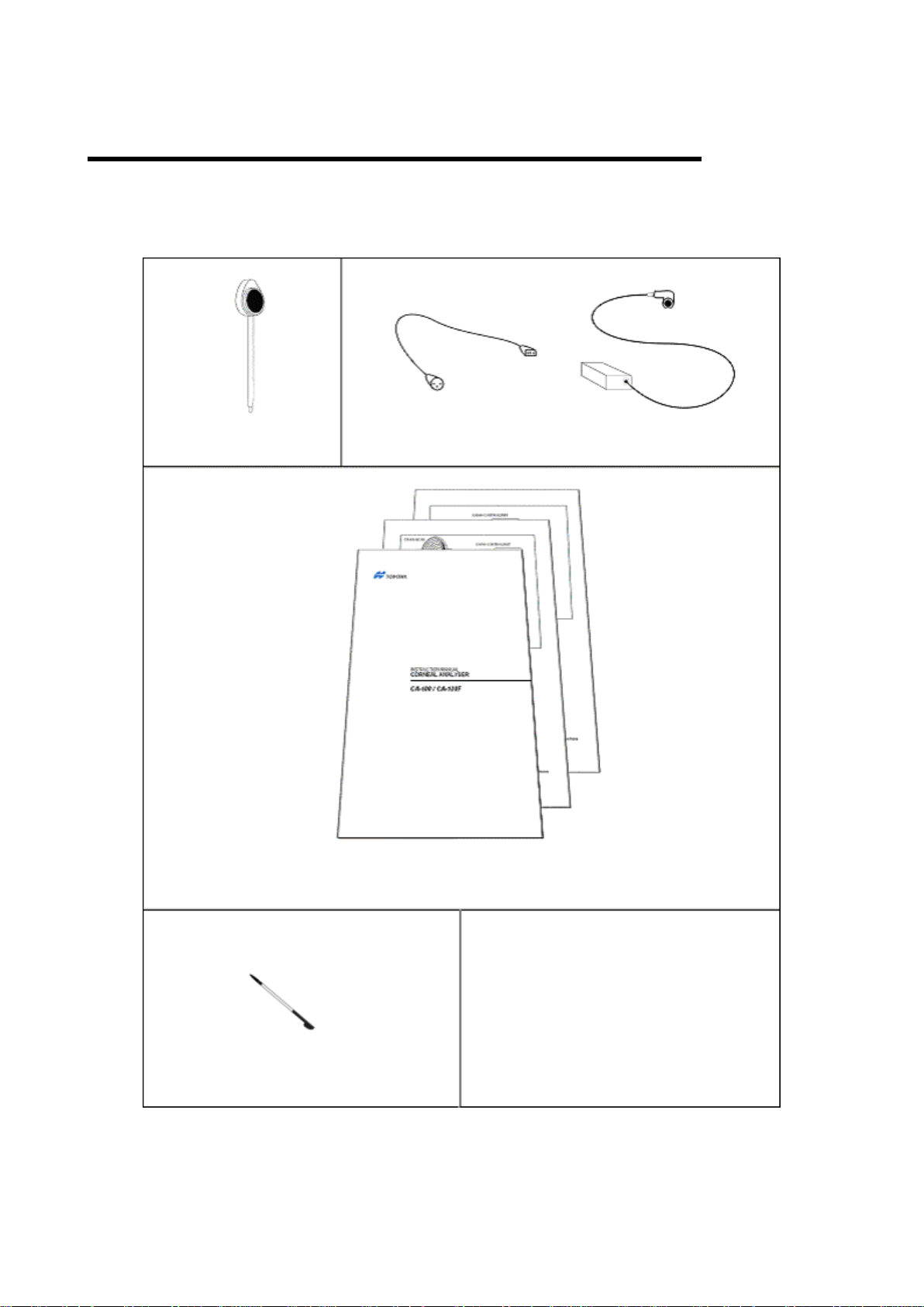
CA-200F STANDARD ACCESSORIES
TOUCH SCREEN PEN
USB EXTENSION CABLE
INSTRUCTION AND ASSEMBLY MANUAL
CALIBRATION TEST
POWER CABLE
TRANSFORMER
The following accessories are included in the package:
CA-200F Corneal Analyser - Rev. 7 16/01/2012
15
Page 16

CA-200F Corneal Analyser - Rev. 7 16/01/2012
Chinrest
Sliding plate
Transformer
Table
Power socket
PC
Wireless connection
LAN connection
(cross cable)
INSTALLATION
Hardware installation (point-to-point network configuration)
Software installation
See “CA-Series Installation Manual” included in the CA-200F Setup CD.
16
Page 17
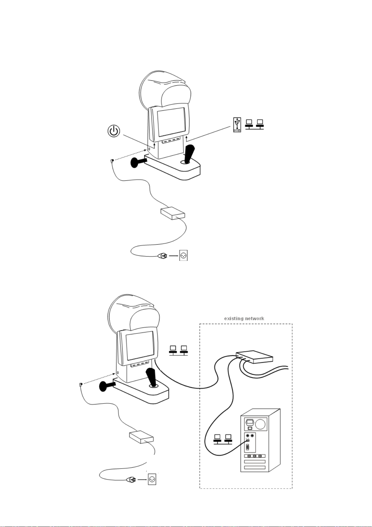
Installation without network connection
Transformer
Power
socket
Power socket
Transformer
LAN connection
(paired cable)
Network Hub
PC
CA-200F Corneal Analyser - Rev. 7 16/01/2012
Connection to an existing network
17
Page 18

CA-200F Corneal Analyser - Rev. 7 16/01/2012
1. BASIC OPERATIONS
GENERAL DESCRIPTION
CA-200F is a corneal analyser with the following functions:
Cornea image acquisition and topographic analysis;
Dynamic pupillometry acquisition: recording of a sequence of images of the pupil as the light
conditions change. Static pupillometry acquisition in controlled light conditions (photopic, mesopic
and scotopic);
Fluorescein analysis: picture and/or movie acquisition to view contact lens positioning and cornea
acquisition to assess its artefacts and the lachrymal film (rupture time);
Analysis of wavefront corneal aberrations generated by the front surface of the cornea with Zernike
analysis: information on the optical properties of the cornea and the optical problems that may
disturb sight;
Contact lens simulation: the software selects from a database the lens best suited to the eye and
allows comparing different lenses;
Intraocular lens calculation (Toric IOL).
SOFTWARE RELEASE: from 1.0.1
ACQUISITION
When the device is turned on, the software is automatically loaded.
CA-200F can operate in two different ways: exchanging data with a PC or stand-alone.
Described below are the acquisition procedures for operation connected to a remote PC as well as in stand-
alone mode.
ACQUISITION WHEN CONNECTED TO A PC
To use the instrument connected to a remote PC (Wi-Fi or LAN), the PC Link software module must be
activated (see the “Module Update” section in “Administrator Tools”).
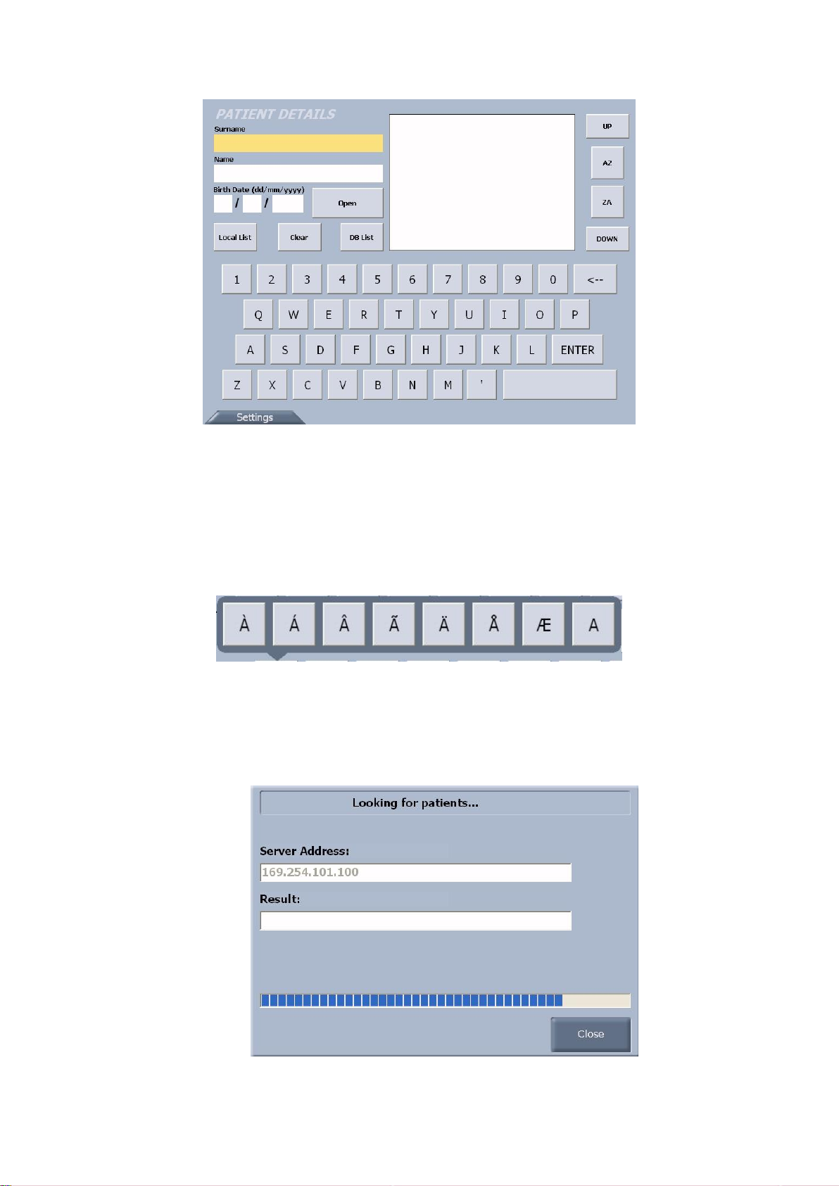
When the instrument is turned on, the Patient Details window is displayed (fig. 1-1).
18
Page 19
CA-200F Corneal Analyser - Rev. 7 16/01/2012
fig. 1-1
You can insert a new patient or select an existing patient from the database of the PC connected to the
analyser.
To insert a new patient, fill in the patient details fields using the on-screen keyboard. If you need to insert
special characters, keep pressing the letter buttons: a panel with the choice of the possible characters for the
selected letter will appear (example fig. 1-2).
Press the “Open” button to access the acquisition window for the patient just inserted.
fig. 1-2
There are two ways to select an existing patient from the database of the PC:
Type in the patient’s name or surname or part of them and press the “DB List” button to open a
dialogue window with the PC (fig. 1-3).
fig. 1-3
19
Page 20

CA-200F Corneal Analyser - Rev. 7 16/01/2012
If the communication between the PC and the device is correctly established, the patients that match
the criteria entered will be displayed in the dedicated section (fig. 1-4) . Select the patient and press
the “Open” button or double-tap on the patient’s name to access the acquisition window.
If the communication between the PC and the device is not correctly established, see the
“Troubleshooting” section.
fig. 1-4
Press the “DB List” button to open the dialogue window with the PC: the patients list will appear in
the dedicated section (fig. 1-5). Use the “UP” and “DOWN” buttons to scroll the list and select the
patient as described above.
fig. 1-5
20
Page 21

CA-200F Corneal Analyser - Rev. 7 16/01/2012
The following buttons are also available in the Patient Details window:
Local List: opens a list with locally stored items (fig. 1-6). This button is only active when there are
locally stored items available.
Transfer to PC: transfers the selected files to the PC. If there are transfer problems,
see the “Troubleshooting” section;
Close: closes the dialogue window;
Delete Selected: deletes the selected files.
fig. 1-6
Clear : clears the contents of the list and the patient details fields;
AZ : sorts the patients list in alphabetical order;
ZA : sorts the patients list in reverse alphabetical order;
Settings: open the settings panel (fig. 1-7). Only the buttons for language setting, keyboard layout
setting and system management tools are active. For more details on using these buttons, see the
“Settings” section.
fig. 1-7
21
Page 22

CA-200F Corneal Analyser - Rev. 7 16/01/2012
fig. 1-9
fig. 1-10
fig. 1-11
ACQUISITION ENVIRONMENT
The acquisition environment is divided into three sections: Topography, Pupillometry and Fluorescein.
Each time you access acquisition, the instrument is set to topography (fig. 1-8).
The following buttons are available in the acquisition window:
R and L: indicates the eye being acquired, highlighted in yellow.
TOPO, PUPI, FLUO: indicates the type of acquisition (highlighted in yellow); you can select from
topography, pupillometry and fluorescein.
Acquisition Gallery
A preview of the acquired image is shown in the acquisition gallery (fig. 1-9, fig. 1-10, fig. 1-11 for
topography, pupillometry and fluorescein, respectively).
fig. 1-8
22
Page 23

CA-200F Corneal Analyser - Rev. 7 16/01/2012
The images are numbered progressively and each of them is associated with the eye to which they refer and
the type of acquisition.
For topography and fluorescein, you can tap on a preview image to select or deselect it. The selected
images are displayed normally, while those not selected are dark.
To calculate the topographic map, the software automatically selects the best image for each eye.
Press the arrow buttons to scroll up and down all the images.
Functions
Settings
Tap on “Settings” to open the settings panel. See the “Settings” section.
Close/Save
Tap on “Close/Save” to open the options (fig. 1-12):
Store Locally: locally stores the data acquired. This data can be sent to the PC using the “Local
List” button in the Patient Details window;
Transfer to PC: sends the data acquired directly to the PC. If there are transfer problems, see the
“Troubleshooting” section;
Close: closes the current patient and returns to the Patient Details window.
fig. 1-12
Reset
The “Reset” button deletes the images in the gallery of the examination highlighted for the current patient.
Processing
The “Processing” button processes the images acquired for the three sections (topography, pupillometry
and fluorescein). If at least one topography image has been acquired, the software by default accesses the
map environment.
23
Page 24

CA-200F Corneal Analyser - Rev. 7 16/01/2012
TOPOGRAPHY
Backlighting of the Placido disc is automatically activated when the acquisition environment is accessed. If
the analyser is not used for a few minutes, the cone turns off; to switch it on again, just push the button on
the joystick as indicated on the screen (fig. 1-13).
fig. 1-13
Acquisition procedure
Align the live image in the center and focus it, then push the joystick button to start acquisition. Move the
instrument forward and backward (following the indications of the red and blue arrows on the screen) to find
the best focus; the system will automatically capture the image. To manually acquire the image, push the
joystick button again; the software will in any case select the image with the best focus.
PUPILLOMETRY
Press the “PUPI” button to acquire the Pupillometry images (fig. 1-14).
You can select from the following types of acquisition:
Dynamic : acquisition of a sequence of images as the light conditions change from scotopic to
photopic and back to scotopic so that you can analyze pupil reaction times and contraction
Photopic
Mesopic
Scotopic
24
Page 25

CA-200F Corneal Analyser - Rev. 7 16/01/2012
fig. 1-14
Acquisition procedure
Align the live image in the center and focus it, then push the joystick button to start acquisition.
You can stop acquisition by pushing the joystick button. Otherwise the acquisition is automatically interrupted
when the sliding bar reaches the end.
FLUORESCEIN
Press the “FLUO” button to access the fluorescein analysis acquisition environment (fig. 1-15).
You can select between picture and movie acquisition.
fig. 1-15
Acquisition procedure
Align the live image in the center and focus it, then push the joystick button to start acquisition.
In case of movies, you can stop acquisition by pushing the joystick button. Otherwise the acquisition is
automatically interrupted when the sliding bar reaches the end.
25
Page 26

CA-200F Corneal Analyser - Rev. 7 16/01/2012
SETTINGS
In the acquisition window press the “Settings” button (fig. 1-16).
The first time the program is started, the default language set is English and keyboard layout is “QWERTY”.
To change the language setting, select the desired language from those that appear when tapping on the
button , press “Set as current language” and then “Close” to set automatic starting with the language
selected.
To change keyboard layout, select the desired layout and press “Set as current layout”. Pressing the
“Close” button, you can see the change in keyboard layout in the Patient Details window.
fig. 1-16
“Acquisition Settings” : open the acquisition settings panel for fluorescein and pupillometry (fig. 1-17).
You can set the LED brightness in fluorescein and the duration of scotopic and photopic controlled light
conditions in dynamic acquisition of the pupil.
“Start Calibration Procedure”: starts the calibration procedure.
“Calibration Check”: starts the calibration check procedure.
“Admin Tools”: opens the instrument administrator panel. See the “Administrator Tools” section.
26
Page 27

CA-200F Corneal Analyser - Rev. 7 16/01/2012
fig. 1-17
ACQUISITION IN STAND-ALONE MODE
To use the instrument in stand-alone mode, the PC Link software module must be deactivated.
The acquisition environment is as shown in fig. 1-18.
fig. 1-18
Tapping on the “New Patient” button, a window opens where you can insert the patient details (fig. 1-19).
27
Page 28

CA-200F Corneal Analyser - Rev. 7 16/01/2012
fig. 1-19
Insert the patient data and tap on the button to close the window. The “New Patient” button
changes to “Close” (fig. 1-20).
Tapping on “Close” the patient data and the gallery are deleted. The “Close” button changes back to “New
Patient“ and then you can insert a new patient.
fig. 1-20
All the other functions of the acquisition environment are the same functions available when the PC Link
module is active (see the paragraph above).
28
Page 29

CA-200F Corneal Analyser - Rev. 7 16/01/2012
TOPOGRAPHIC MAP
In the acquisition window press “Processing” to access the topographic map environment (fig. 1-21).
fig. 1-21
Tap on the “R” or “L” button to view the map of the right eye (R) or the left eye (L).
In the map window you can select the following buttons (fig. 1-22):
Axl or Tan: axial or tangential map
Abs or Nor: absolute or normalized scale
Eye, Map, Ring: to view the image of the eye, the map and the rings
fig. 1-22
Pressing on any point on the map the following information is displayed (fig. 1-23):
Diopters
Radius
Meridians
Altimetry
fig. 1-23
29
Page 30

CA-200F Corneal Analyser - Rev. 7 16/01/2012
fig. 1-26
K: Keratometry
I: Keratorefractive indices
KC:Keratoconus
P: Pupil
Profile
Press the "Profile" button to view the curvature profile along the most curved and the flattest meridian (red
and blue).
The difference is shown in green (fig. 1-24).
fig. 1-24
Tap on the “>>” button to open the panel (fig. 1-25) where you can select (with the arrow buttons) other
meridians along which to view the curvature profile.
fig. 1-25
Select the "<<" button to close the panel and update the profiles viewed.
Press the "Close" button to close the profile panel.
Indices
The diagnostic indices can be selected from the following buttons (fig. 1-26)
30
Page 31

Keratometry
fig. 1-27
Tap on the ”K” button to view the keratometric data (fig. 1-27):
Sim K
Ophthalmometric reading simulation
Meridians
Keratometric data at 3 mm, 5 mm and 7 mm
Emimeridians
Keratometric and emimeridian data at 3 mm, 5 mm and 7 mm
fig. 1-28
Tap on the ”I” button to view the keratorefractive indices (fig. 1-28):
3 and 5 mm astigmatism
Average pupillar power for a 4.5 mm pupil
Asphericity of an 8mm diameter cornea
Longitudinal spherical aberration of a 4.5 mm diameter cornea area
Curvature irregularity calculated on the standard deviation of the instantaneous values
for a 4.5 mm cornea area
Asymmetry between the most curved and the flattest hemisphere calculated for a 4.5
mm diameter cornea area
SAI (Surface Asymmetry Index) represents the surface asymmetry index of a 4.5 mm
diameter cornea area
Keratorefractive indices
CA-200F Corneal Analyser - Rev. 7 16/01/2012
31
Page 32

Keratoconus
fig. 1-29
Tap on the “KC” button to open keratoconus screening with the following information
(fig. 1-29):
AK: Apical curvature. Represents the cornea power at its apex
AGC: apical curvature gradient. Represents the mean variation by unit of length of the
cornea power taking the apical power as reference
SI: difference between the average power of two circular areas centered on the vertical
axis of the rulers and positioned in the lower and upper hemisphere of the cornea,
respectively
Kpi: Keratoconus diagnosis probability index
Based on the combined assessment of the first three indices with the probability index,
there are three different possibilities: topography not compatible with keratoconus
(green); suspected keratoconus (yellow); topography compatible with keratoconus
(red).
If the topography is compatible with keratoconus or indicates suspected keratoconus,
the numerical values of the geometrical cone parameters are shown at the bottom of
the panel, which are:
A: keratoconus area (mm²)
D: Average keratoconus diameter (mm)
r, ø: polar coordinates (mm, °) of the keratoconus barycenter with respect to the center
of the map
RND: keratoconus circularity factor
fig. 1-30
Tap on the “P” button to open the pupil indices (fig. 1-30):
Corneal diameter
KC represents the central keratometry in diopters
Pupil decentralization from the optical axis
Average pupil diameter
Average pupillar power for a 4.5 mm pupil
Pupil
Functions
Settings
Press “Settings” to open map settings.
Report
Use the "Report" button to save the patient data and the map as a PDF file to a USB unit or print the report
on a printer connected to the USB port (fig. 1-31).
Page 33

CA-200F Corneal Analyser - Rev. 7 16/01/2012
33
fig. 1-31
Acquisition
Tap on "Acquisition" to return to the acquisition window.
Modules
Press the "Modules" button to open the software modules (fig. 1-32):
- Fluorescein
- Pupillometry and Zernike (if active in the instrument)
- Contact Lens
- Toric IOL (if enabled)
fig. 1-32
TOPOGRAPHIC MAP SETTINGS
There are two sections for the topographic map settings (fig. 1-33 and fig. 1-34).
Map
Map draw
Select one or more options to customize map display with:
Meridians
3 Zones
Ruler
Grid
Keratometry
Select one of the keratometric indices:
Sim-K
Meridians
Emimeridians
Page 34

CA-200F Corneal Analyser - Rev. 7 16/01/2012
34
Scales
fig. 1-33
fig. 1-34
Map
Select a unit of measure:
Diopters
Millimeters
Asphericity
Select an asphericity unit of measure:
e
SF
p
Q
Page 35

CA-200F Corneal Analyser - Rev. 7 16/01/2012
35
FLUORESCEIN
The fluorescein module (fig. 1-35) allows assessing the physical condition of the cornea and positioning and
dragging the contact lenses.
fig. 1-35
The pictures and movies acquired are viewable in the gallery.
When the fluorescein module is started, the first acquisition in the gallery is displayed in the main window.
Tapping on a picture, it is displayed in the main window.
Tapping on a movie, it automatically starts playing (fig. 1-36). Using the buttons below the main window you
can pause, stop or go forward and back by one frame.
Depending on the selection, the eye to which the picture or movie refers will be highlighted.
The two numbers at the bottom right indicate the number of the image displayed in the main window and the
total number of images in the gallery.
Page 36

CA-200F Corneal Analyser - Rev. 7 16/01/2012
36
fig. 1-37
fig. 1-38
fig. 1-36
Functions
Settings
Opens the fluorescein options window.
Report
Save the report as a PDF file to a USB unit or print it on a connected USB printer.
Acquisition
Returns to the acquisition window.
Close
Tapping on the “Close” button, the system:
- returns to the topographic map environment if you have also acquired topographies in the same
session;
- returns to the acquisition environment in every other cases.
FLUORESCEIN SETTINGS
Press “Grid” and/or “Ruler” to show a grid and/or ruler on the images (fig. 1-37 e fig. 1-38).
Page 37

CA-200F Corneal Analyser - Rev. 7 16/01/2012
37
fig. 1-40
D: Dynamic
P:Photopic
S:Scotopic
M: Mesopic
fig. 1-41
Tap on the “D” button to view the dynamic pupillometry with the following
information (fig. 1-41):
Minimum and maximum values of the average pupil diameters measured in all the
images in the sequence
Cartesian coordinates of the pupil center and standard deviation
Pupil diameter for the frame selected
Cartesian coordinates of the pupil center for the frame selected
PUPILLOMETRY (optional module)
The pupillometry module allows viewing and analyzing the dynamic and static pupillometry (images of the
pupil acquired in controlled light conditions).
The software by default accesses dynamic pupillometry, if acquired (fig. 1-39).
fig. 1-39
Tap on the “R” or “L” button to view the pupillometry of the right or left eye.
You can select the sequence of images to be displayed using the following buttons (fig. 1-40)
Only the buttons for the acquisition done are active.
Dynamic
Page 38

CA-200F Corneal Analyser - Rev. 7 16/01/2012
38
fig. 1-42
Tap on the “P”,”S”, “M” buttons to view the images of the pupil acquired in
photopic, scotopic and mesopic conditions with the following information (fig.
1-42):
Average value and standard deviation of the average pupil diameter in the
sequence acquired
The other information provided is similar to that described for dynamic
pupillometry.
Photopic, Scotopic, Mesopic
Below the main window there are buttons that allow you to view all the frames in sequence, go forward or
back by one frame or return to the first frame. There are also two numbers that indicate the number of the
image displayed and the total number of images that make up the sequence (fig. 1-43).
fig. 1-43
Press the button to delete individual images from the sequence.
Graphs
Press the "Graphs” button to view the pupillometry graphs:
Decentralization (fig. 1-44)
Latency (fig. 1-45)
Statistics (fig. 1-46)
In the above three cases, tapping on “R” or “L” you can view the graphs of the right or left eye.
The “Close” button closes the graphs.
Page 39

39
Decentralization
CA-200F Corneal Analyser - Rev. 7 16/01/2012
fig. 1-44
The green box identifies the pupil center coordinates with respect to the fixation point. The red lines show
how these coordinates vary during dynamic pupillometry acquisition.
On the left-hand side are the minimum and maximum values of the pupil diameter acquired in dynamic
pupillometry and the pupil center, Cartesian and polar coordinates.
Latency
fig. 1-45
The graph shows the acquisition time in seconds on the X-axis and the pupil diameter in millimeters on the
Y-axis in a normalized scale between the minimum and the maximum values.
The trend of the pupil diameter in the acquisition time is hence represented.
On the left-hand side are the minimum and maximum values of the pupil diameter.
Page 40

CA-200F Corneal Analyser - Rev. 7 16/01/2012
40
Considering that dynamic pupillometry consists of acquisition of a sequence of images as the light conditions
change from scotopic to photopic and back to scotopic and that the scotopic (red band) and photopic (green
band) acquisition times can be set in “Settings” in the “Acquisition settings” section, there is also a legend
that explains the meaning of the colors in the graph:
- Red for scotopic acquisition where the white LEDs are off;
- Green for the pupil contraction phase following the change from LEDs off to LEDs on;
- Blue for the pupil dilation phase following the change from LEDs on to LEDs off.
The decentralization and latency graphs are viewable only if a dynamic pupillometry has been acquired.
Statistics
fig. 1-46
The graph represents the statistical percentile value of the sample for each acquisition in controlled light
conditions.
As indicated in the legend on the right-hand side and the values shown on the left, the red line represents
the mean value of the sample, the blue square the interval of values between the percentile at 25% and at
75%, the green line the interval of values between the percentile at 10% and at 90% and the pink circle the
values outside this interval.
The statistics graph is viewable only if images of the pupil have been acquired in photopic, mesopic or
scotopic conditions.
Functions
Settings
Opens the pupillometry settings.
Report
Saves the report as a PDF file to a USB unit or prints it on a connected USB printer.
Acquisition
Returns to the acquisition window.
Close
Tapping on the “Close” button, the system:
- returns to the topographic map environment if you have also acquired topographies in the same
session;
- returns to the acquisition environment in every other cases.
Page 41

CA-200F Corneal Analyser - Rev. 7 16/01/2012
41
fig. 1-47
fig. 1-48
PUPILLOMETRY SETTINGS
Select one or more options to customize the display of the pupil images (fig. 1-47 and fig. 1-48) with:
Grid
Ruler
Ring Center: the center of the pupil will be displayed in blue and the fixation point in red
Pupil: the pupil outline will be displayed in blue
Page 42

CA-200F Corneal Analyser - Rev. 7 16/01/2012
42
ZERNIKE (included with pupillometry module)
The Zernike module allows full display of the wavefront aberrations generated by the front surface of the
cornea. The results of the Zernike analysis are displayed by means of numerical indices and graphic
representations (fig. 1-49).
fig. 1-49
Tap on the “R” or “L” button to view the Zernike analysis results for the right or the left eye.
When the module is started, the aberration maps are displayed:
OPD map: shows the map of the total aberration which corresponds to the sum of all the aberration
components and the RMS value which allows quantifying the deviation with respect to an ideal
wavefront.
Zernike expansion coefficient histograms: each histogram represents the weight of the
corresponding polynomial.
Primary aberration maps:
Astigmatism: shows the map, the entity of diopters, the axis and the RMS value;
Spherical aberration: shows the map, the amount of longitudinal spherical aberration in
diopters and the RMS value;
Coma: shows the map, the RMS value and the direction;
High order aberrations: groups all the components of a higher order than the primary
components; shows the map and the RMS value.
Tap on “Graphs” at the top left to view the summary of the visual quality (fig. 1-50).
In this window you can view:
OPD map;
Pyramid of Zernike coefficients: represents the numerical value of each coefficient on a scale of
grey; the greater the coefficient the greater the color contrast with the background of the pyramid;
Point Spread Function: represents the intensity of the wavefront in the retina;
Spot Diagram: represents the space distribution of the wavefront on the retina;
High and low contrast optotypes: represent the actual sight of the patient.
Press the “Maps” button to return to map display.
Page 43

CA-200F Corneal Analyser - Rev. 7 16/01/2012
43
fig. 1-50
Functions
Pupil
The “Pupil” button opens a panel (fig. 1-51) where you can select the pupil diameter (in a range between 2
mm and 7.5 mm) to see how the aberrations change as the pupil diameter changes.
fig. 1-51
Report
Save the report as a PDF file to a USB unit or print it on a connected USB printer.
Acquisition
Returns to the acquisition window.
Close
Returns to the topographic map environment.
Page 44

44
LENSES
The lenses module (fig. 1-52) simulates contact lens positioning.
CA-200F Corneal Analyser - Rev. 7 16/01/2012
fig. 1-52
Tap on the "R" or "L" button to view the lens in the right or left eye.
Selecting a lens
You can select a lens from the database by tapping on the menu on the optical bar (fig. 1-53).
fig. 1-53
Brand
Press the "Brand” button to select a brand (fig. 1-54). The best lens in the manufacturer’s database is
automatically selected.
Model
Only the models of the brand selected will be shown (fig. 1-55).
Diameter
Select a diameter (fig. 1-56).
Base Curve
Select a base curve (fig. 1-57).
Page 45

CA-200F Corneal Analyser - Rev. 7 16/01/2012
45
fig. 1-54
fig. 1-55
fig. 1-56
fig. 1-57
Profile
Tap on the "Profile" button to view the lachrymal film profile under the lens selected (fig. 1-58).
fig. 1-58
Tap on the “>>” button to open the panel (fig. 1-59) where you can select (with the arrow buttons) other
meridians along which to view the lachrymal film profile.
fig. 1-59
Select the "<<" button to close the panel and update the profiles viewed.
Press the "Close" button to close the profile.
Page 46

CA-200F Corneal Analyser - Rev. 7 16/01/2012
46
fig. 1-60
Ref: Refraction
K/L:Keratometry/Limbus
T/D:Tilt/Decentration
Pref: Lens preferences
fig. 1-61
fig. 1-62
Lens indices and options
You can select the following buttons (fig. 1-60)
Refraction
Shows the refraction values (fig. 1-61).
Tap on “>>” to set the refraction values (fig. 1-62). Use the arrow buttons to set the individual values. Select
the "<<" button to close the panel and apply the refraction values.
Keratometry/Limbus
Shows the keratometric indices and the corneal diameter (fig. 1-63). Press “Edit” to change the iris outline.
fig. 1-63
Page 47

47
Tilt/Decentration
CA-200F Corneal Analyser - Rev. 7 16/01/2012
fig. 1-64
Tilt
Displays the four buttons in lens simulation (fig. 1-64). Press the buttons to set the different tilt values. The
"Reset" button resets the initial condition.
Decentration
Drags the lens to the desired position. The "Reset" button resets the initial lens position.
Lens preferences
Tap on the "Pref" button to open the lens preferences window (fig. 1-65).
fig. 1-65
You can add maximum 32 lenses. Use the "<<"and ">>" buttons to view all the lens preferences.
Tap on “Lens preview” to open lens positioning with the lens selected.
Delete a lens by pressing the "X" button in the top right corner of the preview.
Page 48

CA-200F Corneal Analyser - Rev. 7 16/01/2012
48
The "Reset" button deletes all the lens preferences.
The "Close" button closes the window.
Functions
Settings
Opens the lens options window.
Report
Save the report as a PDF file to a USB unit or print it on a connected USB printer.
Add
Tap on "Add" to add the current lens to your preferences.
Close
Returns to the topographic map environment.
LENS SETTINGS
Manufacturers
fig. 1-66
Allows managing your own lens database. A brand list is displayed on the left-hand side (fig. 1-66).
Tap on the “Import” button to add new manufacturers to the database. You can import new manufacturers
using a USB pen-drive.
To export a particular lens brand, select it and press the "Export Selected" button. The data will be copied
to a USB pen-drive. In the same way, press "Export All" to export all the manufacturers.
Tap on the "Delete" button to delete a brand from the database
Select the desired brand and press "Set Default" to set automatic starting with these lenses.
Page 49

49
Lenses
CA-200F Corneal Analyser - Rev. 7 16/01/2012
fig. 1-67
Set the apical clearance using the up/down arrows (fig. 1-67).
Page 50

CA-200F Corneal Analyser - Rev. 7 16/01/2012
50
TORIC IOL (optional module)
NOTE: All the information contained in this paragraph are referred to IOL version 2.0.0.5.
The Toric IOL software module is the tool to calculate Oculentis toric intraocular lenses.
fig. 1-68
The initial window (fig. 1-68) shows the summary of the cornea diagnosis with all the information on corneal
regularity, symmetry and keratoconus screening. Tap on the "R" and "L" buttons to go from the right to the
left eye and vice versa.
Tap on the "Quit" button to exit the Toric IOL software.
Tap on the "Next" button to access the input window (fig. 1-69).
Patient Information
Insert the required patient information.
fig. 1-69
Page 51

51
Surgeon Information
Select a surgeon from the list.
Tap on "Details" for the surgeon details (fig. 1-70).
Tap on "Add new" to add a new surgeon.
CA-200F Corneal Analyser - Rev. 7 16/01/2012
fig. 1-70
Tap on "Close" to close the surgeon details.
Tap on “Delete” to delete the surgeon data.
Tap on "Save" to save the surgeon details.
Tap on "Next" to input pre-op information (fig. 1-71).
Pre-Op Information
fig. 1-71
Page 52

CA-200F Corneal Analyser - Rev. 7 16/01/2012
52
The following information is required:
Biometry Procedure
Axial Length
ACD
IOL Spherical Power
Surgically Induced Astigmatism
Incision Location
Tap on "Calculate IOL" to view the result window with the pre-op and post-op information (fig. 1-72).
fig. 1-72
Tap on "Order Form" to print the report on a connected USB printer or to save it as a PDF file to a USB unit
(fig. 1-73).
fig. 1-73
Tap on "Send Order" to open a dialogue window for file transfer and remote printing (fig. 1-74).
fig. 1-74
Page 53

CA-200F Corneal Analyser - Rev. 7 16/01/2012
53
ADMINISTRATOR TOOLS
In the acquisition window tap on "Settings" and then on "Admin Tools" (fig. 1-75).
Information:
S/N = Serial number
S/V = Software version
Applications:
Upgrade
Module Update
Wi-Fi Settings Wizard
Terminate
Network Settings
fig. 1-75
Upgrade
To upgrade the software, carry out the following operations:
- Decompress the upgrade package in the root (main folder) of an empty and FAT32 formatted USB
pen-drive
- Insert the USB pen-drive in the CA-200F device
- Tap on the “Upgrade” button
The system will be restarted for the first time. Disconnect the USB pen, otherwise the system will not be
started.
Access the “Admin Tools” menu again, insert the USB pen-drive and press the “Upgrade” button.
The upgrade process is completed with a second system restart. Disconnect the USB pen-drive when done.
Module Update
Some software functions are defined as "modules".
Some modules are optional and hence not available by default. See the “Module Update” section
Wi-Fi Settings Wizard
Start the Wizard for configuration of the Wi-Fi connection to the remote PCs. For detailed instructions, see "
CA-Series Installation Manual".
Page 54

CA-200F Corneal Analyser - Rev. 7 16/01/2012
54
Terminate
Press "Terminate" to close the CA-200F application and return to the Windows desktop.
Network Settings
Press “Network Settings” (fig. 1-76).
Use the “Search” button to start the search for the IP address for connection to the PC.
Use the “Test” button to test the network to check that the connection has been established.
fig. 1-76
If there are no known clients in the search list, tapping on the “DB List” button, the network settings panel
will be open (fig. 1-77).
fig. 1-77
Press “Search” and “Test” to find and test the IP address for connection to the PC.
Tap on “Close” to return to the Patient Details window; the dialogue window with the PC to search for the
patient list will automatically be started.
Page 55

CA-200F Corneal Analyser - Rev. 7 16/01/2012
55
MODULE UPDATE
From the “Admin Tools” panel, tap on the "Module Update" button (fig. 1-78).
Here you will find the sections for activation of the optional and software modules.
fig. 1-78
Optional Module
To activate the optional modules, carry out the following operations:
- Decompress the update package in the root (main folder) of an empty and FAT32 formatted USB pen-
drive
- Press the “Module Update” button
Software Modules
The Toric IOL and PC Link modules are software modules that need to be activated.
For the Toric IOL module, when tapping on the "Update" button, the license agreement is displayed (fig.
1-79). Tap on “AGREE” to confirm and use the IOL software on your own responsibility.
For the PC Link module, tap on the “Disabled” button: the module will be activated when the program is
restarted.
fig. 1-79
Page 56

CA-200F Corneal Analyser - Rev. 7 16/01/2012
56
2. CA-200F PC-SOFTWARE
SOFTWARE INSTALLATION
See the “CA-Series Installation Manual” included in the Setup CD.
CA-200F PC SOFTWARE SETTINGS
For details, refer to the “Corneal Analyser Software Manual”.
To open the settings window, in the main “Corneal Analyser Software” window (fig. 2-1) tap on “File” and
then on “Settings” (fig. 2-2).
fig. 2-1
Page 57

CA-200F Corneal Analyser - Rev. 7 16/01/2012
57
fig. 2-2
To select the acquisition device, tap on “Corneal Analyser”, select CA-200F as instrument and press “Ok”
to close the window and save the changes. Tap on “Cancel” to close the window without saving the
changes.
Page 58

58
3. TROUBLESHOOTING
Problem
Solution
Impossible to communicate with the PC
(This may occur while searching the patient list
and/or when sending patient data to the PC)
Check that the network has been installed as
described in the “CA-Series Installation Manual”
Check that the PC is on and that the Wi-Fi or LAN
connection is active
Check that the IP address for connection to the PC
has been set correctly
The calibration check has failed
Repeat the measurement, and if the problem
persists, contact TOPCON Technical Service to have
the instrument recalibrated
The standard deviation after an acquisition session is
greater than 0.12 D
Repeat the measurement
The CA-200F display is black
Check that the CA-200F device is on
Check that the power cables are properly connected
CA-200F Corneal Analyser - Rev. 7 16/01/2012
Page 59

59
4. REFERENCES
CA-100/200 chinrest
CA-200 clens
CA-200 caldev
CA-100/200 baseplate
CA-100/200 baseplate
no chinrest possible
Default accessories:
Optional accessories:
CA-200F Corneal Analyser - Rev. 7 16/01/2012
Page 60

60
5. SPECIFICATIONS
KERATOSCOPIC CONE
24 rings equally distributed on a 43D sphere
POINTS ANALYZED
over100,000
POINTS MEASURED
over10,000
CORNEA COVERAGE
0.3mm (minimum diameter on a 43D sphere) to 10.5mm on a normal eye
DIOPTRIC POWER RANGE
1D to over 120D
RESOLUTION
+/- 0.01D, 1 micron
ACCURACY
Axial curvature 0.03mm, altimetric data 2 m at 4mm
FOCUS SYSTEM
Autofocus with autocapture
PUPILLOMETRY
Integrated
FLUORESCENCE
Integrated
OUTPUT PORTS
USB, LAN
Temperature
10-40°C
Relative humidity
30-75% (no condensate)
Atmospheric pressure
700-1060 hPa
Temperature
10-40°C
Relative humidity
30-75% (no condensate)
Atmospheric pressure
700-1060 hPa
Power source
AC 100-240V 47-63 Hz
Power consumption
3.2A
CA-200F
H:320mm
W:455mm
L:250mm
Weight:6.8 kg
CA100/200 chinrest
H:70mm
W:257mm
L:180mm
Weight:0.8 kg
CA100/200 baseplate
H:75mm
W:145mm
L:253mm
Weight:1.9 kg
Operating system
WINDOWS XP
Processor
Pentium III or later
RAM
256MB ( minimum )
Connections
Wi-Fi or LAN
Software protection
USB key hardware
Operating system
Widows XP Embedded
Processor
Pentium M 1GHz
RAM
512 Mbytes
Connections
Wi-Fi Integrated, LAN Integrated
Software protection
Integrated
Technical Specifications
Environmental conditions
Operation
CA-200F Corneal Analyser - Rev. 7 16/01/2012
Storage
Electrical specifications
Mechanical specifications
External computer specifications
Internal computer specifications
Page 61

CA-200F Corneal Analyser - Rev. 7 16/01/2012
61
6. MAINTENANCE
Instrument cleaning and maintenance
Do not clean the plastic parts with solvents such as benzene or ether, as they may cause discoloring of
the parts and decomposition of the material.
If the instrument is dirty, clean the surface with a dry cloth.
If there are permanent stains on the surface of the Placido disc, please contact Topcon Support for
replacement.
Before using the chinrest on another patient, clean and disinfect the supports that come into contact
with the forehead and chin with neutral detergents.
Calibration check
It is absolutely necessary to test the calibration when the instrument has been transported from one
place to another and when it has suffered physical impact or sudden temperature changes.
Position the calibration test instrument (fig. 6-1) in the dedicated hole on the chinrest. Check that the
calibration tool is perfectly aligned to the instrument. If the device is positioned correctly, you should see all
the rings of the Placido disc reflecting on the surface of the hemisphere, in the center (fig. 6-2).
fig. 6-1
Page 62

CA-200F Corneal Analyser - Rev. 7 16/01/2012
62
Right alignment
Wrong alignment
fig. 6-2
From the CA-200F software, select the "Settings" button and then the “Calibration Check" function (fig.
6-3).
fig. 6-3
Following the instructions given at the bottom of the window, acquire the sphere eight times with a radius of
8 mm.
If the calibration is correct, a window will appear with the message "Calibration Check: POSITIVE".
If the test has a negative outcome, retry. If the outcome is negative for three consecutive times, contact
Technical Service to have the device recalibrated.
To interrupt calibration and return to the acquisition environment, press the “Close” button.
 Loading...