

Page 1

"2
/PERATORlS-ANUAL
Page 2

Page 3

POSITIONING SYSTEMS
BR-1
Operator’s Manual
Part Number 7010-0796
Rev A
©Copyright Topcon Positioning Systems, Inc.
March, 2007
All contents in this manual are copyrighted by Topcon. All rights reserved.
The information contained herein may not be used, accessed, copied, stored,
displayed, sold, modified, published, or distributed, or otherwise reproduced
without express written consent from Topcon.
Topcon only sells GPS products into Precision Markets.
Please go to www.topcongps.com for detailed market information.
Page 4

ECO#2978
Page 5

TOC
Table of Contents
Preface .................................................................. v
Terms and Conditions ...................................................... v
Manual Conventions ........................................................ viii
Chapter 1
Introduction .......................................................... 1-1
Principles of Operation .................................................... 1-2
GNSS Overview ........................................................ 1-2
Calculating Absolute Positions ........................... 1-3
Calculating Differential Positions ...................... 1-4
Essential Components for Quality Surveying .... 1-5
Conclusion .......................................................... 1-5
Coastal Navigation Beacons DGPS Service ............. 1-6
BR-1 Overview ......................................................... 1-6
Getting Acquainted with the BR-1 .................................. 1-7
Rechargeable Battery ................................................ 1-7
BR-1 MINTER .......................................................... 1-8
BR-1 Ports ................................................................. 1-9
Carry Case and Belt ......................................................... 1-10
System Cables .................................................................. 1-11
BR-1 Configuration Software .......................................... 1-11
Optional Accessories ....................................................... 1-12
Chapter 2
Preparing the BR-1 for Use ................................. 2-1
Powering the BR-1 .......................................................... 2-1
Charging the Battery ................................................. 2-1
Charging and Battery Storage Notes ......................... 2-3
Installing the Battery ................................................. 2-4
Starting the BR-1 ............................................................. 2-5
P/N 7010-0796
i
Page 6

Table of Contents
Installing BR-1 Control Center onto a Computer ............ 2-5
Configuring the BR-1 ....................................................... 2-6
Bluetooth Module Configuration ..................................... 2-8
Chapter 3
Surveying with the BR-1 ..................................... 3-1
BR-1 Surveying with the GMS-2 ..................................... 3-2
BR-1 Surveying with an External GPS Receiver ............. 3-3
Chapter 4
Troubleshooting .................................................. 4-1
Check This First! .............................................................. 4-1
Troubleshooting Quick List ............................................. 4-2
Resetting the Beacon Receiver ......................................... 4-2
Charging/Powering Problems .......................................... 4-2
BR-1 Problems ................................................................. 4-3
Bluetooth Problems .......................................................... 4-3
Obtaining Technical Support ........................................... 4-4
Phone ......................................................................... 4-4
E-mail ........................................................................ 4-4
Website ...................................................................... 4-5
Appendix A
BR-1 Control Center Software Reference .......... A-1
General Settings ............................................................... A-4
Connecting to BR-1 Control Center ................................. A-5
Setting up the Ports .......................................................... A-6
Setting up Channels .......................................................... A-7
Setting up the Almanac .................................................... A-9
Power Board Parameters and Led Parameters ................. A-10
Spectrum Analyzer ........................................................... A-11
Appendix B
Specifications ...................................................... B-1
BR-1 Specifications .......................................................... B-1
General Details .......................................................... B-1
Connector Specifications .................................................. B-3
Serial Connector ........................................................ B-3
ii
BR-1 Operator’s Manual
Page 7

Table of Contents
Appendix C
Safety Warnings ................................................... C-1
General Warnings ........................................................... C-1
Battery Pack Warnings .................................................. C-1
Usage Warnings .............................................................. C-2
Appendix D
Regulatory Information ........................................ D-1
FCC Compliance ............................................................. D-1
Canadian Emission Labeling Requirements .................... D-2
Community of Europe Compliance ................................. D-2
WEEE Directive .............................................................. D-3
Appendix E
Warranty Terms .................................................... E-1
Index
P/N 7010-0796
iii
Page 8

Table of Contents
Notes:
iv
BR-1 Operator’s Manual
Page 9

Preface
Preface
Thank you for purchasing this Topcon product. The materials
available in this Manual (the “Manual”) have been prepared by
Topcon Positioning Systems, Inc. (“TPS”) for owners of Topcon
products, and are designed to assist owners with the use of the
receiver and its use is subject to these terms and conditions (the
“Terms and Conditions”).
NOTICE
Please read these Terms and Conditions carefully.
Terms and Conditions
USE This product is designed to be used by a professional. The user
should have a good knowledge of the safe use of the product and
implement the types of safety procedures recommended by the local
government protection agency for both private use and commercial
job sites.
COPYRIGHT All information contained in this Manual is the
intellectual property of, and copyrighted material of TPS. All rights
are reserved. You may not use, access, copy, store, display, create
derivative works of, sell, modify, publish, distribute, or allow any
third party access to, any graphics, content, information or data in this
Manual without TPS’ express written consent and may only use such
information for the care and operation of your receiver. The
information and data in this Manual are a valuable asset of TPS and
are developed by the expenditure of considerable work, time and
money, and are the result of original selection, coordination and
arrangement by TPS.
P/N 7010-0796
v
Page 10

Preface
TRADEMARKS GMS-2, GMS Tools, BTManager, TopSURV,
TopPAD, HiPer, Topcon and Topcon Positioning Systems are
trademarks or registered trademarks of TPS. Microsoft, Windows,
ActiveSync, and the Windows logo are either trademarks or registered
trademarks of Microsoft Corporation in the United States and/or other
countries. The Bluetooth® word mark and logos are owned by
Bluetooth SIG, Inc. and any use of such marks by Topcon Positioning
Systems, Inc. is used under license. Other product and company
names mentioned herein may be trademarks of their respective
owners.
DISCLAIMER OF WARRANTY EXCEPT FOR ANY
WARRANTIES IN AN APPENDIX OR A WARRANTY CARD
ACCOMPANYING THE PRODUCT, THIS MANUAL AND THE
RECEIVER ARE PROVIDED “AS-IS.” THERE ARE NO OTHER
WARRANTIES. TPS DISCLAIMS ANY IMPLIED WARRANTY
OF MERCHANTABILITY OR FITNESS FOR ANY PARTICULAR
USE OR PURPOSE. TPS AND ITS DISTRIBUTORS SHALL NOT
BE LIABLE FOR TECHNICAL OR EDITORIAL ERRORS OR
OMISSIONS CONTAINED HEREIN; NOR FOR INCIDENTAL OR
CONSEQUENTIAL DAMAGES RESULTING FROM THE
FURNISHING, PERFORMANCE OR USE OF THIS MATERIAL
OR THE RECEIVER. SUCH DISCLAIMED DAMAGES
INCLUDE BUT ARE NOT LIMITED TO LOSS OF TIME, LOSS
OR DESTRUCTION OF DATA, LOSS OF PROFIT, SAVINGS OR
REVENUE, OR LOSS OF THE PRODUCT’S USE. IN ADDITION
TPS IS NOT RESPONSIBLE OR LIABLE FOR DAMAGES OR
COSTS INCURRED IN CONNECTION WITH OBTAINING
SUBSTITUTE PRODUCTS OR SOFTWARE, CLAIMS BY
OTHERS, INCONVENIENCE, OR ANY OTHER COSTS. IN ANY
EVENT, TPS SHALL HAVE NO LIABILITY FOR DAMAGES OR
OTHERWISE TO YOU OR ANY OTHER PERSON OR ENTITY
IN EXCESS OF THE PURCHASE PRICE FOR THE RECEIVER.
LICENSE AGREEMENT Use of any computer programs or software
supplied by TPS or downloaded from a TPS website (the “Software”)
in connection with the receiver constitutes acceptance of these Terms
and Conditions in this Manual and an agreement to abide by these
Terms and Conditions. The user is granted a personal, non-exclusive,
vi
BR-1 Operator’s Manual
Page 11

Terms and Conditions
non-transferable license to use such Software under the terms stated
herein and in any case only with a single receiver or single computer.
You may not assign or transfer the Software or this license without
the express written consent of TPS. This license is effective until
terminated. You may terminate the license at any time by destroying
the Software and Manual. TPS may terminate the license if you fail to
comply with any of the Terms or Conditions. You agree to destroy the
Software and manual upon termination of your use of the receiver. All
ownership, copyright and other intellectual property rights in and to
the Software belong to TPS. If these license terms are not acceptable,
return any unused software and manual.
CONFIDENTIALITY This Manual, its contents and the Software
(collectively, the “Confidential Information”) are the confidential and
proprietary information of TPS. You agree to treat TPS’ Confidential
Information with a degree of care no less stringent that the degree of
care you would use in safeguarding your own most valuable trade
secrets. Nothing in this paragraph shall restrict you from disclosing
Confidential Information to your employees as may be necessary or
appropriate to operate or care for the receiver. Such employees must
also keep the Confidentiality Information confidential. In the event you
become legally compelled to disclose any of the Confidential
Information, you shall give TPS immediate notice so that it may seek a
protective order or other appropriate remedy.
WEBSITE; OTHER STATEMENTS No statement contained at the
TPS website (or any other website) or in any other advertisements or
TPS literature or made by an employee or independent contractor of
TPS modifies these Terms and Conditions (including the Software
license, warranty and limitation of liability).
SAFETY Improper use of the receiver can lead to injury to persons or
property and/or malfunction of the product. The receiver should only
be repaired by authorized TPS warranty service centers. Users should
review and heed the safety warnings in an Appendix.
P/N 7010-0796
vii
Page 12

Preface
MISCELLANEOUS The above Terms and Conditions may be
amended, modified, superseded, or canceled, at any time by TPS. The
above Terms and Conditions will be governed by, and construed in
accordance with, the laws of the State of California, without reference
to conflict of laws.
Manual Conventions
This manual uses the following conventions:
Example Description
FileExit Click the File menu and click Exit.
Connection Indicates the name of a dialog box or screen.
Frequency Indicates a field on a dialog box or screen, or a tab
within a dialog box or screen.
Enter Press or click the button or key labeled Enter.
CAUTION
viii
NOTE
TIP
NOTICE
Further information to note about the configuration,
maintenance, or setup of a system.
Supplementary information that can help you
configure, maintain, or set up a system.
Supplementary information that can have an affect
on system operation, system performance,
measurements, or personal safety.
Notification that an action has the potential to
adversely affect system operation, system
performance, data integrity, or personal health.
BR-1 Operator’s Manual
Page 13

WARNING
Manual Conventions
Notification that an action will result in system
damage, loss of data, loss of warranty, or personal
injury.
DANGER
Under no circumstances should this action be
performed.
P/N 7010-0796
ix
Page 14

Preface
Notes:
x
BR-1 Operator’s Manual
Page 15
Chapter 1
Introduction
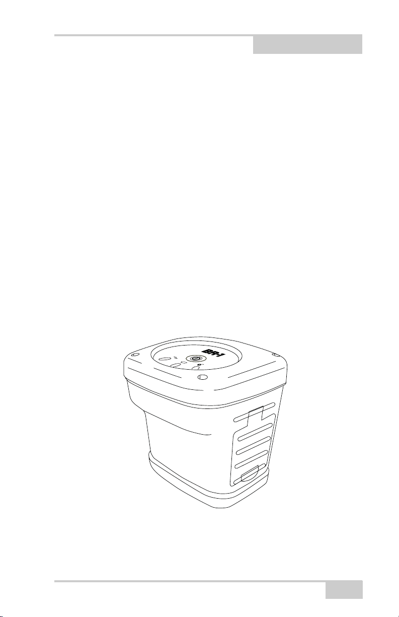
The BR-1 is a receiver that detects radio beacon signals, and is built to
be the most advanced, compact, and portable receiver for the GIS
surveying market.
The BR-1 receiver is a single-function, single-purpose receiver
intended for precision markets. Precision markets means markets for
equipment, subsystems, components and software for surveying,
construction, commercial mapping, civil engineering, precision
agriculture and land-based construction and agriculture machine
control, photogrammetry mapping, hydrographic and any use
reasonably related to the foregoing.
When combined with the GMS-2, the BR-1 provides the
functionality, accuracy, availability, and integrity needed for fast and
easy data collection.
P/N 7010-0796
Figure 1-1. BR-1
1-1
Page 16

Introduction
Principles of Operation
Surveying with the right GPS receiver can provide users accurate and
precise positioning, a requirement for any surveying project.
This section gives an overview of existing and proposed Global
Navigation Satellite Systems (GNSS) and receiver functions to help
you understand and apply basic operating principles, allowing you to
get the most out of your receiver. Also discussed are the principles
behind surveying with Differential GPS, and using radio beacon
signals as the source of corrections to locate unknown points.
GNSS Overview
Currently, the following three global navigation satellite systems
(GNSS) offer line-of-site radio navigation and positioning, velocity,
and time services on a global, all-weather, 24-hour scale to any user
equipped with a GNSS tracking receiver on or near the Earth’s
surface:
• GPS – the Global Positioning System maintained and operated by
the United States Department of Defense. For information on the
status of this system, visit the US Naval Observatory website
(http://tycho.usno.navy.mil/) or the US Coast Guard website
(http://www.navcen.uscg.gov/).
• GLONASS – the Global Navigation Satellite System maintained
and operated by the Russian Federation Ministry of Defense. For
information on the status of this system, visit the Ministry of
Defense website (http://www.glonass-center.ru/frame_e.html).
• GALILEO – an upcoming global positioning system maintained
and operated by Galileo Industries, a joint venture of several
European space agencies working closely with the European
Space Agency. Unlike GPS and GLONASS, this is a civil
endeavor and is currently in the development and validation
stage. For information on the status of this system, visit the
Galileo Industries website (http://www.galileo-industries.net).
1-2
BR-1 Operator’s Manual
Page 17

Principles of Operation
Despite numerous technical differences in the implementation of
these systems, satellite positioning systems have three essential
components:
• Space – GPS, GLONASS, and GALILEO satellites orbit
approximately 12,000 nautical miles above Earth and are
equipped with a clock and radio. These satellites broadcast digital
information (ephemerides, almanacs, time&frequency
corrections, etc.).
• Control – Ground stations located around the Earth that monitor
the satellites and upload data, including clock corrections and
new ephemerides (satellite positions as a function of time), to
ensure the satellites transmit data properly.
• User – The community and military that use GNSS receivers and
the corresponding satellites to calculate positions.
Calculating Absolute Positions
When calculating an absolute position, a stationary or moving
receiver determines its three-dimensional position with respect to the
origin of an Earth-Center Earth-Fixed coordinate system. To calculate
this position, the receiver measures the distance (called pseudoranges) between it and at least four satellites. The measured pseudoranges are corrected for clock differences (receiver and satellites) and
signal propagation delays due to atmospheric effects. The positions of
the satellites are computed from the ephemeris data transmitted to the
receiver in navigation messages. When using a single satellite system,
the minimum number of satellites needed to compute a position is
four. In a mixed satellite scenario (GPS, GLONASS, GALILEO), the
receiver must lock onto at least five satellites to obtain an absolute
position.
To provide fault tolerance using only GPS or only GLONASS, the
receiver must lock onto a fifth satellite. Six satellites will provide
fault tolerance in mixed scenarios.
P/N 7010-0796
1-3
Page 18

Introduction
Calculating Differential Positions
DGPS, or Differential GPS, typically uses the measurements from
two or more remote receivers to calculate the difference (corrections)
between measurements, thus providing more accurate position
solutions.
With DGPS, one receiver is placed at a known, surveyed location and
is referred to as the reference receiver or base station. Another
receiver is placed at an unknown, location and is referred to as the
remote receiver or rover. The reference station collects the range
measurements from each GPS satellite in view and forms the
differences (corrections) between the calculated distance to the
satellites and the measured pseudo-ranges to the satellites.
These corrections are then built up to the industry standard (RTCM or
various proprietary standards) established for transmitting differential
corrections and broadcast to the remote receiver(s) using a data
communication link. The remote receiver applies the transmitted
DGPS corrections to its range measurements of the same satellites.
Using this technique, the spatially correlated errors—such as satellite
orbital errors, ionospheric errors, and tropospheric errors—can be
significantly reduced, thus improving the position solution accuracy
of the GPS.
A number of differential positioning implementations exist, including
post-processing surveying, real-time kinematic surveying, maritime
radio beacons, geostationary satellites (as with the OmniSTAR
service), and the wide area augmentation system (WAAS) service.
The real-time kinematic (RTK) method is the most precise method of
real-time surveying. RTK requires at least two receivers collecting
navigation data and communication data link between the receivers.
One of the receivers is usually at a known location (Base) and the
other is at an unknown location (Rover). The Base receiver collects
carrier phase measurements, generates RTK corrections, and sends
this data to the Rover receiver. The Rover processes this transmitted
data with its own carrier phase observations to compute its relative
position with high accuracy, achieving an RTK accuracy of up to 1 cm
horizontal and 1.5 cm vertical.
1-4
BR-1 Operator’s Manual
Page 19

Principles of Operation
Essential Components for Quality Surveying
Achieving quality position results requires the following elements:
• Accuracy – The accuracy of a position primarily depends upon
the satellite geometry (Geometric Dilution of Precision, or
GDOP) and the measurement (ranging) errors.
– Differential positioning (DGPS and RTK) strongly mitigates
atmospheric and orbital errors, and counteracts Selective
Availability (SA) signals the US Department of Defense
transmits with GPS signals.
– The more satellites in view, the stronger the signal, the lower
the DOP number, the higher positioning accuracy.
• Availability – The availability of satellites affects the calculation
of valid positions. The more visible satellites available, the more
valid and accurate the position. Natural and man-made objects
can block, interrupt, and distort signals, lowering the number of
available satellites and adversely affecting signal reception.
• Integrity – Fault tolerance allows a position to have greater
integrity, increasing accuracy. Several factors combine to provide
fault tolerance, including:
– Receiver Autonomous Integrity Monitoring (RAIM) detects
faulty GPS and GLONASS satellites and removes them from
the position calculation.
– Five or more visible satellites for only GPS or only
GLONASS; six or more satellites for mixed scenarios.
– Wide Area Augmentation Systems (WAAS, EGNOS, etc.)
creates and transmit, along with DGPS corrections, data
integrity information (for example, satellite health warnings).
– Current ephemerides and almanacs.
Conclusion
This overview simply outlines the basics of satellite positioning. For
more detailed information, visit the TPS website.
P/N 7010-0796
1-5
Page 20

Introduction
Coastal Navigation Beacons DGPS Service
Throughout the world, a number of coastal radio beacon networks
have been established to improve the accuracy of maritime navigation
around harbors and critical waterways. These beacon networks
provide correction information to GIS users with the proper
equipment. Since beacon stations act as the known reference point,
the repetitive set up, survey, and configuration of a base station has
been eliminated. A beacon system provides ±3 meter accuracy
In the United States, the coastal navigation beacons are managed by
the United States Coast Guard and provide differential correction
service in coastal areas and much of the interior of the United States.
In other parts of the world, coastal navigation beacons modeled after
the US Coast Guard system are available. Check with your local
maritime authority to learn more about services available in your area.
The Beacon system is provided free of charge in the United States.
• For detailed information on the coastal navigation beacon system
in the United States, visit the US Coast Guard’s Navigation
Center website (www.navcen.uscg.gov).
• For detailed information on the coastal navigation beacon system
in other parts of the world, visit the International Association of
Marine Aids to Navigation and Lighthouse Authorities website
(http://www.iala-aism.org/web/index.html).
BR-1 Overview
The BR-1 is a 4-channel radio beacon receiver. Included in the system
is beacon and Bluetooth. Bluetooth provides a connection with an
external device such as GMS-2. This cable free connection allows for
smart field work.
The Beacon receiver component of the BR-1 can receive the
DGPS correction data from the Beacon reference station. The BR-1
searches and receives the beacon signal and automatically exports the
correction data after the unit is powered on. Because the BR-1 has a
4-channel beacon receiver, it simultaneously receives up to 4 beacon
1-6
BR-1 Operator’s Manual
Page 21

Getting Acquainted with the BR-1
signals. The BR-1 then chooses the optimal beacon station, then
exports the correction data from the station.
Getting Acquainted with the
BR-1
The BR-1 is a beacon receiver. A serial port with Bluetooth® wireless
technology provides communication paths with other devices.
The standard BR-1 package contains the following items:
• BR-1 beacon receiver with rechargeable battery
• Soft carry case and belt
• Unit-to-PC serial cable and power converter/adapter cable
• Configuration software and assorted documentation
For more details on accessories and options available for the BR-1,
contact your local Topcon dealer.
Rechargeable Battery
The BR-1 comes equipped with a rechargeable battery (Figure 1-2)
for powering the unit. The battery can be charged in the unit or in an
optional battery charger.
NOTICE
NOTICE
P/N 7010-0796
The BR-1 cannot receive a Beacon signal while
charging.
You may hear a high pitch sound while charging the
battery. The sound does not cause a problem.
Continue charging the battery.
1-7
Page 22
Introduction
The battery provides fifteen hours of operation, depending on the
mode of the receiver.
Battery
Figure 1-2. GMS-2 Battery
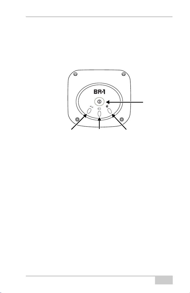
BR-1 MINTER
The Minimum INTERface for the BR-1 turns on the receiver and has
LEDs to monitor battery status and communication status.
•The power button turns the receiver on and off.
•The status LED indicates the status of the beacon signal:
– Green blink: receiving a beacon signal, where each blink
indicates a detected beacon station.
– Red blink: searching for a beacon signal or no beacon signal
detected.
•The power LED indicates the level of charge in the battery:
During Use During Charge
– Green blink: battery has a full
charge (more than 80%).
– Yellow blink: intermediate
charge.
– Fast blink: battery is
charging.
– Solid Green: battery is
fully charged.
– Red blink: battery requires
charging (less than 20%).
1-8
BR-1 Operator’s Manual
Page 23
Getting Acquainted with the BR-1
•The Bluetooth LED indicates the level of activity at the
Bluetooth wireless technology module:
– Blue blink: the module is on and a connection has been
established.
– Slow Blue blink: waiting for a connection.
Signal Status LED Battery Status LED Bluetooth Status LED
Figure 1-3. BR-1 MINTER
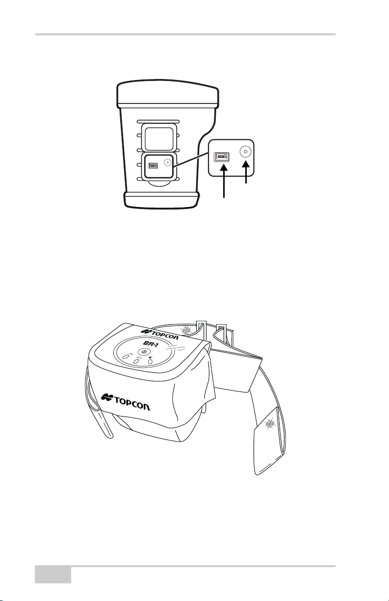
BR-1 Ports
Power Button
The BR-1 has the following two ports:
• Serial – used for communication between the internal beacon
module (port A of the module) and an external device.
• Power – used to connect the BR-1 to an external power source.
This port is used to charge the battery.
P/N 7010-0796
1-9
Page 24
Introduction
Power
Serial (port A)
Figure 1-4. BR-1 Ports
Carry Case and Belt
The carry case for the BR-1 has soft sides for comfort and is attached
to an adjustable comfort-belt. The top of the case is clear for easy
access to the MINTER. The case is waterproof.
1-10
Figure 1-5. BR-1 Carry Case and Belt
BR-1 Operator’s Manual
Page 25

System Cables
System Cables
The standard BR-1 package includes communication and power
cables (Table 1-1).
Table 1-1. BR-1 Package Cables
Cable Description Cable Illustration
AC Power cable and
adapter
Connects the BR-1 to a
grounded outlet.
Serial cable
Connects the BR-1 to a
computer for high-speed
data transfer and receiver
configuration.
BR-1 Configuration Software
The BR-1 comes with BR-1 Control Center software for configuring
the ports, satellite almanac, radio channels, power usage, and other
functions. The software is installed on a computer and will be used
for configuring the BR-1 prior to performing fieldwork.
Figure 1-6. BR-1 Control Center
P/N 7010-0796
1-11
Page 26

Introduction
Optional Accessories
Table 1-2 gives a brief list of optional accessories that can be used
with the GMS-2. For more details on accessories and package options
available for the BR-1, contact your local Topcon dealer.
Table 1-2. GMS-2 Optional Accessories
Accessory Illustration
External Battery Charger
Connects to an outlet to
charge the battery outside
the unit.
Extra Battery
Provides a backup source of
power.
Be sure to turn off the unit
before switching batteries.
Serial cables
• Connects the BR-1 to a
HiPer or GB series GPS
receiver
• Connects the BR-1 to a
GMS-2 controller/
receiver
1-12
BR-1 Operator’s Manual
Page 27

Chapter 2
Preparing the BR-1 for
Use
Before using the BR-1, check that its battery is fully charged. While
the BR-1 is ready to use without needing to be configured, perform
any configurations in the office and prior to performing fieldwork.
Powering the BR-1
The BR-1 uses a BT-62Q battery for it’s primary power source. The
battery will last up to fifteen hours during continuous use.
Charging the Battery
The AC/DC converter provides power to the BR-1 and charges the
battery. The BR-1 cannot receive a beacon signal while the battery is
charging.
You may hear a high pitch sound while charging the
NOTICE
To charge the battery using the adapter, (Figure 2-1 on page 2-2)
plug the connector into the power port of the BR-1. Then plug the
converter into a grounded outlet. The battery will be fully charged in
about three hours.
P/N 7010-0796
battery. The sound does not cause any problem, so
it is okay to continue charging the battery.
2-1
Page 28

Preparing the BR-1 for Use
The power LED indicates the level of charge in the battery:
During Use During Charge
• Green blink: battery has a full charge
(more than 80%).
• Yellow blink: intermediate charge.
• Red blink: battery requires charging
(less than 20%).
• Fast blink: battery is charging.
• Solid Green: battery is fully charged.
To Grounded Outlet
Figure 2-1. Charging the Battery in the BR-1
To charge the battery using the optional charger, (Figure 2-2)
remove the battery from the BR-1 (see “Installing the Battery” on
page 2-3 for details) and slide it onto the charger. Plug the charger in
to a grounded outlet.
2-2
BR-1 Operator’s Manual
Page 29

Powering the BR-1
To Gr ounded
Outlet
Figure 2-2. Charging the Battery in the Charger
Charging and Battery Storage Notes
Keep the following in mind for proper charging, maintenance, and
storage of the battery.
• Only recharge the battery at room temperature, approximately
50°F to 104°F (10°C to 40°C). Charging at a high temperature
will increase the time it takes to charge the battery.
• The battery will discharge during storage. Always check the
battery charge before using the BR-1.
• Charge a stored battery every 7 days. Allowing a battery to
become discharged can reduce the overall performance of the
battery and charge efficiency.
• The charger may become somewhat heated while charging the
BR-1.
Installing the Battery
The rechargeable battery can be charged using either the power port
(see “Charging the Battery” on page 2-1) or the optional charger.
P/N 7010-0796
2-3
Page 30

Preparing the BR-1 for Use
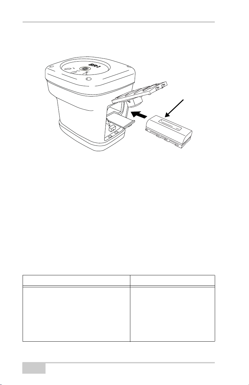
Follow these steps to remove/replace the battery (Figure 2-3 on
page 2-4).
1. Open the battery cover. If needed, pull out the shelf to remove the
(discharged) battery.
2. Insert a fully charged battery, sliding it into place. Then close the
battery cover.
If the battery cover does not close, rotate the battery
TIP
180° to snap it into place.
2-4
Battery shelf
pulled out
Figure 2-3. Installing the Battery
BR-1 Operator’s Manual
Page 31

Starting the BR-1
Starting the BR-1
To start the BR-1, briefly press the power button. The LEDs light up.
Press Power
to Start
Figure 2-4. Press Power to Start the BR-1
Once the unit is turned on it begins to search for beacon signals and
outputs correction information via the serial or Bluetooth port.
Installing BR-1 Control Center onto a Computer
The BR-1 Control Center is a utility software used to configure the
BR-1. This software installs onto a desktop computer or notebook
computer. Computer requirements for the BR-1 Control Center are:
Windows® 98 or newer and an RS-232C (serial).
1. Create a BR-1 Control Center folder on your hard drive and place
the compressed BR-1 Control Center software file (retrieved from
either the website or the CD) in this folder.
2. Create a shortcut on the computer’s desktop for quick access to
BR-1 Control Center. Extract Program and Create Shortcut
To uninstall BR-1 Control Center, navigate to the location of the *.exe
file. Select the file and press Delete.
P/N 7010-0796
2-5
Page 32

Preparing the BR-1 for Use
Configuring the BR-1
The BR-1 default settings are the automatic mode settings. The BR-1
searches for a signal, then automatically produces the RTCM
correction from that signal, without special settings. The BR-1 can
use its default settings, without changing parameters, for the majority
of its use.
The following steps describe how to change the parameters to receive
specific frequencies. For details on the BR-1 Control Center, see
Appendix A.
1. Turn on the BR-1.
2. Connect the BR-1 and a computer using the serial cable.
Use the serial cable
to connect the BR-1
and a computer.
Figure 2-5. Connect BR-1 and Computer
3. Start BR-1 Control Center. Select the COM port and click
Connect.
Figure 2-6. Connect BOB-CDU and the BR-1
2-6
BR-1 Operator’s Manual
Page 33

Configuring the BR-1
4. Configure Channel A for specific frequency setup.
• Frequency channel: Select desired frequency
• Frequency scanning mode in case of signal loss condition: Check
“Stay”
• Frequency scanning mode after beacon signal was found: Select
“Stay”
5. Click Apply to save the settings.
Figure 2-7. Select Channel Information
6. Configure the Ports for RTCM output settings.
• RTCM Settings: Enable Channel A.
Figure 2-8. Configure RTCM Settings
7. Click Apply to save your settings (Figure 2-8).
8. On the Connect tab, check “Disconnect with RTCM output
mode”. Then click Disconnect.
P/N 7010-0796
2-7
Page 34

Preparing the BR-1 for Use
NOTICE
You must click Disconnect to prevent port
communication problems with the computer.
Figure 2-9. Disconnect with RTCM Output
Bluetooth Module Configuration
Use BTCONF, Topcon’s Bluetooth module’s configuration program,
and your computer to:
• access the Bluetooth wireless technology module
• configure the Bluetooth module
• check or change the module’s configuration
To access the Bluetooth wireless technology module, first download
and install BTCONF, then connect your computer and the receiver
and run the configuration program.
1. Create or locate the following folder:
C:\Program Files\TPS\BTCONF
2. Download btconf.zip from the TPS website and unzip it into the
BTCONF folder. This file contains Btconf.exe, the executable
file for the Bluetooth module configuration program.
2-8
BR-1 Operator’s Manual
Page 35

Bluetooth Module Configuration
Each time you run BTCONF and configure the Bluetooth module,
BTCONF saves your settings in a file (btconf.ini). BTCONF
automatically updates the file each time you make changes to the
Bluetooth module’s settings.
To maintain unique Bluetooth module settings for
TIP
different purposes, keep copies of BTCONF in
separate folders.
To uninstall BTCONF, delete any applicable BTCONF directories or
folders, and any BTCONF shortcuts.
Once you have BTCONF available, follow these steps to configure
the Bluetooth module.
1. Using the RS232 cable, connect the serial port of your computer
(usually COM1) to the receiver’s serial port A. If needed, turn on
the receiver and computer.
2. Run the Bluetooth module configuration program (Btconf.exe)
(Figure 2-10).
Figure 2-10. Bluetooth Module Configuration Main Screen
Notice that the lower left corner shows a “Disconnected” status
for the computer and Bluetooth module.
For BTCONF version and copyright information, click the About
button.
P/N 7010-0796
2-9
Page 36

Preparing the BR-1 for Use
3. From the drop-down list in the upper left corner, select the
computer serial port (usually COM1) used for communication
(Figure 2-11).
4. Click Connect to connect the computer and Bluetooth module
(Figure 2-11).
Figure 2-11. Select Communication Port and Click Connect
Once the receiver and computer connect through BTCONF, the
Identification tab (Figure 2-12) displays the following
information:
• Bluetooth name – the name of the Bluetooth module.
• Bluetooth address – the unique electronic address for the
module.
• Firmware version – the current firmware version of the
Bluetooth module.
• The COM port and baud rate display in the lower left corner.
2-10
BR-1 Operator’s Manual
Page 37

Bluetooth Module Configuration
Figure 2-12. BTCONF Identification Tab
5. Click the Parameters tab (Figure 2-13 on page 2-11). The
Parameters tab sets identifying and security information for your
Bluetooth module. The security section allows you to set data
security and unauthorized access parameters for the Bluetooth
module.
6. Enter up to 14 characters to set a unique name for the Bluetooth
module (Figure 2-13), and click Apply.
Figure 2-13. BTCONF Parameters Tab
7. To set security parameters (Figure 2-14 on page 2-12), enter and
enable the following, then click Apply:
• Bluetooth PIN – enter up to 16 characters to specify a
personal identification number for the Bluetooth module.
P/N 7010-0796
2-11
Page 38

Preparing the BR-1 for Use
• Encryption – enable to have the Bluetooth module encrypt
wirelessly sent data. To read encrypted data, the user must
have the same PIN used in the device that sent the data.
• Authentication – enable to require a PIN before two
Bluetooth enabled devices (such as, the receiver and a
computer) can establish a communication link. The two
devices must use the same PIN.
NOTICE
If you do not need security settings, leave these
parameters disabled.
Figure 2-14. BTCONF Security Parameters
8. Click the Serial Interface tab (Figure 2-15 on page 2-13). Enable
Echo to display Bluetooth module replies and corresponding
commands on the computer terminal. If needed, click Apply.
2-12
BR-1 Operator’s Manual
Page 39

Bluetooth Module Configuration
Figure 2-15. BTCONF Serial Interface Tab
9. Click Disconnect then Exit (Figure 2-16) to quit BTCONF.
P/N 7010-0796
Figure 2-16. Click Disconnect then Exit
2-13
Page 40

Preparing the BR-1 for Use
Notes:
2-14
BR-1 Operator’s Manual
Page 41

Chapter 3
Surveying with the
BR-1
The BR-1 can be used as a stand-alone Beacon receiver, with
Topcon’s GMS-2, or with an external GPS receiver to provide
correction data. The BR-1 provides direct connection to devices via a
serial port or Bluetooth wireless technology.
GMS-2 Receiver/
Controller (optional)
Battery
Recharger
(optional)
AC/DCPower
Converter
Computer
(commercially sold)
GPS Receiver
(optional)
NOTICE
Serial Cable
Serial Cable for
GMS-2 to BR-1 (optional)
Serial Cable for
GPS receiver to BR-1 (optional)
Figure 3-1. GMS-2 System Connections
Refer to the GMS-2 Operator’s Manual for GMS-2
setup and configurations.
When connected to the GMS-2 or other GPS receiver, the BR-1
Beacon receiver provides correction data for better position accuracy.
P/N 7010-0796
3-1
Page 42

Surveying with the BR-1
BR-1 Surveying with the GMS-2
When surveying with the BR-1 in a GMS-2 configuration, the Beacon
receiver provides DGPS correction data from the Beacon station.
1. Complete any required set up steps for the BR-1 as described in
Chapter 2.
2. In the field, turn on the BR-1.
• If using a serial connection, make sure to connect the optional
GMS-2-to-BR-1 serial cable to both devices.
• If using a Bluetooth wireless technology connection, make
sure BTManager on the GMS-2 is open and detects the BR-1.
In BTManager, the BR-1 is considered an “uncategorized”
device. Refer to the GMS-2 Operator’s Manual for details on
BTManager.
3. Using BTManager on the GMS-2, connect to the BR-1.
Connect GMS-2 and
BR-1 Receiver via Bluetooth
Figure 3-2. BR-1 and GMS-2 Setup
4. Configure the controller (GMS-2) for data collection as described
in the corresponding software manual.
NOTICE
Ensure the survey configuration is for an external
receiver.
5. Via the data collection software, begin logging data.
6. When you reach a location to record a point, pause and press the
Enter button on the controller. Wait until the point is recorded
before moving to the next location.
3-2
BR-1 Operator’s Manual
Page 43

BR-1 Surveying with an External GPS Receiver
BR-1 Surveying with an
External GPS Receiver
When surveying with the BR-1 in an external GPS receiver
configuration, the Beacon receiver provides DGPS data correction to
the GPS receiver. When using this system configuration with a data
controller, make sure to connect the BR-1 and GPS receiver using a
port other than the one used for the controller.
1. Complete any required set up steps for the BR-1 as described in
Chapter 2.
2. In the field connect the BR-1 and GPS receiver with a serial
cable, turn on the external GPS reviver and the BR-1.
3. If using a serial connection, make sure to connect the optional
GPS receiver-to-BR-1 serial cable to both devices.
Connect BR-1 and
GPS Receiver via serial cable
Figure 3-3. BR-1 and External GPS Receiver Setup
4. Begin surveying according to the external GPS receiver’s manual.
The surveying may be conducted using just the GPS receiver, or a
controller (such as the FC-200 or GMS-2) also connected to the
the GPS receiver.
P/N 7010-0796
3-3
Page 44

Surveying with the BR-1
Notes:
3-4
BR-1 Operator’s Manual
Page 45

Chapter 4
Troubleshooting
This chapter will help you diagnose and solve some common
problems you may encounter with the BR-1.
Do not attempt to repair equipment yourself. Doing
WARNING
Check This First!
Before contacting Topcon support, check the following:
• Check all external connections (cable and wireless).
• Check all power sources for drained batteries or incorrectly
connected batteries/cables.
• Check that the most current firmware is downloaded onto the
receiver. Check the TPS website for the latest updates.
so will void your warranty and may damage the
hardware.
Then, try the resetting the hardware. See “Resetting the Beacon
Receiver” on page 4-2.
If the problem persists, see the following sections for other solutions.
P/N 7010-0796
4-1
Page 46

Troubleshooting
Troubleshooting Quick List
To reset the hardware, see “Resetting the Beacon Receiver” on
page 4-2.
For power problems:
If “The BR-1 does not power up.” see page 4-3.
For general BR-1 problems:
If “The BR-1 is not receiving data (corrections) from a Beacon
station.” see page 4-3.
If “The BR-1 is not transmitting data (corrections).” see page 4-4.
For Bluetooth problems:
If “Cannot connect to BR-1 via Bluetooth.” see page 4-4.
If “The BR-1 is no longer connected via Bluetooth.” see page 4-4.
Resetting the Beacon Receiver
Only perform a hardware reset when the BR-1 has become
completely unresponsive. A hardware reset will revert all settings to
defaults.
1. Power off the BR-1.
2. Press and hold the power button.
3. The Status LED lights and Bluetooth LED lights will become
solid after ten seconds.
4. Release the power button.
5. Press the power button to turn off the unit.
4-2
BR-1 Operator’s Manual
Page 47

Charging/Powering Problems
Charging/Powering Problems
The BR-1 does not power up.
D The batteries may be discharged.
• Connect the BR-1 to a grounded outlet to charge the battery.
See “Charging the Battery” on page 2-1.
• Insert a fully charged battery. See “Installing the Battery” on
page 2-3.
D The charging cable may be disconnected or damaged.
Check that the cable is securely connected and undamaged.
D The BR-1 may have a defective charger or defective internal
battery.
If, after changing the battery or connecting an external power
source, the BR-1 still does not power up, contact TPS
Customer Support for advice.
BR-1 Problems
The following are some of the most commonly encountered problems
with the BR-1.
The BR-1 is not receiving data (corrections) from a Beacon
station.
D Check that the correct frequency has been selected. See
“Configuring the BR-1” on page 2-6 for selecting Beacon
frequencies.
P/N 7010-0796
4-3
Page 48

Troubleshooting
The BR-1 is not transmitting data (corrections).
D Check the Bluetooth LED. The LED will be blue when a
connection has been established.
D Check the serial cable connections. The connectors should be
securely plugged in.
D Check that the port settings (Port A and Port B) are setup as
RTCM output mode.
Bluetooth Problems
The following are some of the most commonly encountered problems
with the BR-1.
Cannot connect to BR-1 via Bluetooth.
D Check the Bluetooth setting. If there is a PIN setting, use the
BR-1 Bluetooth PIN for the device PIN.
The BR-1 is no longer connected via Bluetooth.
D Check the Bluetooth LED. The LED will be blue when a
connection has been established.
D Check the connection at the other device.
Obtaining Technical Support
If the troubleshooting hints and tips in this Operator’s Manual fail to
remedy the problem, contact TPS Customer Support.
Before contacting TPS Customer support about any problems with
the unit, see “Check This First!” on page 4-1 for some solutions that
may fix the issue.
4-4
BR-1 Operator’s Manual
Page 49

Obtaining Technical Support
Phone
To contact TPS Customer Support by phone, call:
1-866-4TOPCON (1-866-486-7266)
Monday through Friday
5:00am to 5:00pm, Pacific time
To contact TPS Customer Support via e-mail, use one of the
following electronic mail addresses (Table 4-1).
Table 4-1. Technical Support E-mail
For Questions Related To... Use...
Hardware (receivers, antennas, firmware) hardware@topcon.com
GPS+ and 3DMC psg@topcon.com
OAF options@topcon.com
RTK rtk@topcon.com
PC-CDU pccdu@topcon.com
If in doubt... support@topcon.com
For quick and effective support, provide a detailed
TIP
description of the problem as described below.
When e-mailing TPS customer support, provide the following
information for better, faster service:
1. The device’s model and configuration settings.
2. The serial number of the device (located on the bottom of the
unit).
3. The symptoms and/or error codes/messages that precede and
follow the problem.
4. The activities being tried when the problem occurs. If possible,
include the exact steps being taken up to when the error message
or other problem occurs.
5. How regularly the problem occurs.
P/N 7010-0796
4-5
Page 50

Troubleshooting
Generally, a customer support representative will reply within 24
hours, depending on the severity of the problem.
Website
The Topcon Positioning Systems website provides current
information about Topcon’s line of products. The support area of the
website provides access to frequently asked questions, configuration
procedures, manuals, e-mail support, etc.
To access the TPS website, use: www.topconpositioning.com
4-6
BR-1 Operator’s Manual
Page 51

Appendix A
BR-1 Control Center
Software Reference
BR-1 Control Center is a simple utility that connects to the internal
modules of the BR-1 for unit configuration and unit details. Table A-1
summarizes the screens and settings in BR-1 Control Center.
Table A-1. BR-1 Control Center Quick Reference
Connect
Connect to the BR-1
by pressing the
Connect button.
Select your
connected port
number. The
software
automatically
searches for the
proper baud rate and
connects to the desired rate.
Port: select your connected port on your computer.
General
This tab applies
factory defaults,
resets the receiver,
displays firmware
information (see the
“About” row on
page A-2).
P/N 7010-0796
A-1
Page 52

BR-1 Control Center Software Reference
Table A-1. BR-1 Control Center Quick Reference (Continued)
About
This screen displays
current firmware
versions for the
receiver and power
boards.
Ports
This tab applies
settings to the BR-1
ports. The ports have
the following default
settings:
•Port A – serial
• Port B – Bluetooth
• Port C – power
See “Setting up the
Ports” on page A-6 for details.
Channel A, B, C, D
These tabs applies
settings to the various
channels used to
track Beacon
transmissions.
See “Setting up
Channels” on
page A-7 for details
on changing these
settings.
A-2
BR-1 Operator’s Manual
Page 53

Table A-1. BR-1 Control Center Quick Reference (Continued)
Almanac
Parameters
This tab provides
settings for selecting
the almanac number
and its parameters.
See “Setting up the
Almanac” on
page A-9 for details.
Power Board and
LED Parameters
This tab displays
information on the
current power status.
See “Power Board
Parameters and Led
Parameters” on
page A-10 for details.
Spectrum
Analyzer
This tab displays the
spectrum input for
the Beacon receiver.
See “Spectrum
Analyzer” on
page A-11 for details.
P/N 7010-0796
A-3
Page 54
BR-1 Control Center Software Reference
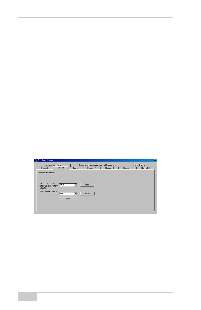
General Settings
The General Settings screen can restore the parameters to their
factory default settings, as well as reset the device. In order to restore
or reset, select the desired parameter and click Apply.
• Set beacon receiver setup/almanac factory defaults
– setup: restores parameter defaults
– Almanac: clears almanac information
• Reset beacon receiver
– Cold: rests receiver firmware, and restores parameters to
the factory default.
– Receiver: receiver firmware is reset.
– Flash_prog: resets flash memory, parameters are restored
to the factory default.
– Bluetooth_prog: resets Bluetooth
– Pwrbrd_prog: resets the power board.
A-4
Figure A-1. General Settings Screen
BR-1 Operator’s Manual
Page 55

Connecting to BR-1 Control Center
Connecting to BR-1 Control
Center
The BR-1 uses either a serial port or Bluetooth wireless technology to
connect to a computer, and thus to BR-1 Control Center.
1. Connect the BR-1 and a computer using the serial cable.
Use the serial cable
to connect the BR-1
and a computer.
Figure A-2. Connect BR-1 and Computer
2. Start BR-1 Control Center. Select the COM port and rate to
connect to the BR-1 and click Connect.
3. Click Disconnect to exit the connection. To exit with RTCM
output mode, turn on “Exit with RTCM output mode” then click
Disconnect.
Figure A-3. Connect BR-1 Control Center and the BR-1
P/N 7010-0796
A-5
Page 56

BR-1 Control Center Software Reference
Setting up the Ports
The BR-1 has three ports, two physical ports and one Bluetooth port.
By default, the serial port is considered port A, the Bluetooth wireless
technology port is port B, and the power port is port C. The Port’s
TabSheet displays the port’s current state and mode.
1. After connecting BR-1 Control Center to the BR-1, click the
Ports tab.
2. Click Refresh to view the current settings.
3. Select the following settings for the desired port:
•Mode:
– Rtcm: RTCM output mode
– Cmd: Command mode
– None
• Data Exit: Edit the character set to interrupt the RTCM output
mode.
• RTCM setting: Allows you to edit/enable the channel for
RTCM output. The BR-1 has 4 channels (A,B,C,D), which
allow the BR-1 to receive up to 4 beacon station signals. The
BR-1 selects the best RTCM data from the enabled channel,
for output.
4. Click Apply. Continue with other set up activities, or click
Disconnect on the Connect tab and the close button to quit
BR-1 Control Center.
A-6
BR-1 Operator’s Manual
Page 57

Setting up Channels
Figure A-4. BR-1 Ports Settings
Setting up Channels
The BR-1 supports up to four separate channels for tracking a Beacon
signal. Each channel has a unique frequency and set up parameters.
The channel tabs also show the current status of the parameters.
These parameters can be edited.
1. After connecting BR-1 Control Center to the BR-1, click the
desired channel tab.
2. Click Refresh to view the current settings.
3. Select the following settings for the channel (Figure A-5 on
page A-9).
• Frequency channel – 283.5Khz-325Khz. Select the desired
frequency.
• Symbol rate – 50,100 or 200. Select the desired rate.
• Almanac entry – Enter the almanac frequency.
• Frequency channel tracking mode:
– None
– Power: Tracks the most powerful signal available.
– Ber: Tracks the signal with a minimum Ber (Block error
P/N 7010-0796
rate).
A-7
Page 58

BR-1 Control Center Software Reference
• Frequency channel mode – Select “prog” or “fft.” fft is faster
than prog, but prog is more reliable.
– Prog: searches the signal carefully with full diapason.
– Fft: searches the signal with the Fast Fourier transform
method.
• Carrier frequency shift estimation method – Select “prog” or
“fft.” fft is faster than prog, but prog is more reliable.
– Prog: searches the signal carefully with full diapason.
– Fft: searches the signal with the Fast Fourier transform
method.
• Symbol speed selector method – Select “prog” or “fft.” fft is
faster than prog, but prog is more reliable.
– Prog: searches the signal carefully with full diapason.
– Fft: searches the signal with the Fast Fourier transform
method.
• Frequency shift – input the frequency shift value within
0.01Hz precision if you can.
• Frequency scanning mode in case of signal loss condition.
– Stay: keeps the current frequency.
– Track: enters the current frequency to the Almanac and
waits until the other channel finds the new frequency.
This new frequency is set to this channel.
– Scan: starts to find the new signal.
• Frequency scanning mode after beacon signal was found.
– Stay: keeps the current frequency.
– Track: keeps the current frequency until another channel
finds a better frequency. This new frequency is set to this
channel.
– Scan: finds the new signal.
A-8
BR-1 Operator’s Manual
Page 59

Setting up the Almanac
• RTCM state– displays the status of the following:
– Norm_op: Operating normally. The receiver receives and
sends out RTCM data.
– Sync_srch: Receiver is searching for a signal.
– Sync_check: Receiver is verifying RTCM messages.
– Idle: no signal input or output.
4. Click Apply (Figure A-5 on page A-9). Continue with other set
up activities, or click Disconnect on the Connect tab and the close
button to quit BR-1 Control Center.
Figure A-5. BR-1 Channel (A) Settings
Setting up the Almanac
The almanac number directly relates to all data collected by the
receiver. The almanac information listed below allows the receiver to
find the beacon signal quickly. Once the BR-1 has acquired the new
beacon signal frequency, the information is stored in the almanac.
Therefore the information can be used in future signal searches.
1. After connecting BR-1 Control Center to the BR-1, click the
Almanac parameters tab.
P/N 7010-0796
A-9
Page 60

BR-1 Control Center Software Reference
The following can be edited:
• Almanac record frequency
•Frequency shift
• Almanac record default symbol rate (select the possible
symbol rate)
• Almanac record actual symbol rate
2. Click Apply (Figure A-6 on page A-10). Continue with other set
up activities, or click Disconnect on the Connect tab and the close
button to quit BR-1 Control Center.
Figure A-6. BR-1 Almanac Settings
Power Board Parameters and Led Parameters
The Power Board Parameters tab displays: the current voltage, charge
degree, and current temperature.
A-10
BR-1 Operator’s Manual
Page 61

Spectrum Analyzer
Figure A-7. Power Board Parameters
Spectrum Analyzer
This tab displays the spectrum of the input signal. You can view the
correlation peak of the received signal. Define the approximate
locking frequency and signal power.
P/N 7010-0796
Figure A-8. Spectrum Analyzer
A-11
Page 62

BR-1 Control Center Software Reference
Notes:
A-12
BR-1 Operator’s Manual
Page 63

Appendix B
Specifications
This TPS product is a 4-channel Beacon receiver with a Bluetooth®
wireless technology module. The portable design allows this device to
be a fully-functional, productive tool at any job.
BR-1 Specifications
The following sections provide specifications for the BR-1 and its
internal components.
General Details
Table B-1 table lists the receiver’s general specifications.
Table B-1. BR-1 General Specifications
Physical
Enclosure Molded ABS
Color Topcon Yellow and Topcon Grey
Dimensions W112 x D:101 x H:122 mm
Weight 0.79 kg (including battery)
Battery Internal, rechargeable/replaceable
Keys (buttons) One key:
Power – On/Off
LEDs Three LEDs:
Bluetooth – indicates Bluetooth wireless technology
connection status
Power – indicates charge level
Signal status – indicates Beacon signal reception status
P/N 7010-0796
B-1
Page 64

Specifications
Environment
Table B-1. BR-1 General Specifications (Continued)
Operating
-20 C° to +50 C°
temperature
Storage temperature -30 C° to +60 C°
Waterproof IP66
Shockproof 1m drop
Power
Internal battery Li-ion, 2200 mAh, 7.4 V; repeatable
Operating time No less than 15 hours with fully charged battery
External power 1 port
Input voltage 8 to 15 V DC (for work)
12 to 15 V DC (for charge battery)
Consumption 1.2 W at 12 V DC
Battery charger Connect the AC adaptor to charge via the power port.
Charging time ~3 hours for full charge
Connectors
Serial port 1 port for communication with the receiver board (port A);
small connector
External power port 1 port; DC Jack type A; for connecting the AC adaptor or
external battery
Communication
Serial port Port A of receiver board
Baud rate =115200, 57600, 38400, 19200, 9600, 4800,
2400, 1200, 600, 300
Flow control = RTC/CTS
Bluetooth Version: Bluetooth standard 1.2; Class 2; Profile: SPP
B-2
BR-1 Operator’s Manual
Page 65

Connector Specifications
Connector Specifications
The BR-1 has two port connectors for power and data input/output.
Serial Connector
The serial connector (Figure B-1) is a sealed receptacle, 5 pin, port.
This connector is configured as port A of the internal Beacon receiver.
Figure B-1. Serial RS232 Connector
P/N 7010-0796
B-3
Page 66

Specifications
Notes:
B-4
BR-1 Operator’s Manual
Page 67

Safety Warnings
General Warnings
TPS receivers are designed for survey and survey
WARNING
related uses (that is, surveying coordinates,
distances, angles and depths, and recording such
measurements). This product should never be used:
• Without the user thoroughly understanding this
manual.
• After disabling safety systems or altering the
product.
• With unauthorized accessories.
• Without proper safeguards at the survey site.
• Contrary to applicable laws, rules, and
regulations.
Appendix C
TPS receivers should never be used in dangerous
DANGER
environments. Use in rain or snow for a limited
period is permitted.
Battery Pack Warnings
Never attempt to open the casing of the removable
DANGER
P/N 7010-0796
battery! Lithium-Ion batteries can be dangerous if
mishandled!
C-1
Page 68

Safety Warnings
DANGER
WARNING
Do not incinerate or the heat battery above 212°
fahrenheit (100° celsius). Excessive heat can cause
serious damage and possible explosion.
Tampering with the batteries by end users or nonfactory authorized technicians will void the
battery’s warranty.
• Do not attempt to open the battery pack or
replace it.
• Do not disassemble the battery pack.
• Do not charge in conditions different than
specified.
• Do not use other than the specified battery
charger.
• Do not short circuit.
• Do not crush or modify.
Usage Warnings
If this product has been dropped, altered,
CAUTION
CAUTION
C-2
transported or shipped without proper packaging, or
otherwise treated without care, erroneous
measurements may occur.
The owner should periodically test this product to
ensure it provides accurate measurements.
Inform TPS immediately if this product does not
function properly.
Only allow authorized TPS warranty service centers
to service or repair this product.
BR-1 Operator’s Manual
Page 69

Appendix D
Regulatory Information
The following sections provide information on this product’s
compliance with government regulations for use.
FCC Compliance
This device complies with Part 15 of the FCC rules. Operation is
subject to the following two conditions:
1. This device may not cause harmful interference, and
2. This device must accept any interference received, including
interference that may cause undesired operation.
This equipment has been tested and found to comply with the limits
for a digital device, pursuant to Part 15 of the FCC rules. These limits
are designed to provide reasonable protection against harmful
interference in residential installations. This equipment generates,
uses, and can radiate radio frequency energy, and if not installed and
used in accordance with the instructions, may cause harmful
interference to radio communications. However, there is no guarantee
that interference will not occur in a particular installation.
If this equipment does cause interference to radio or television
equipment reception, which can be determined by turning the
equipment off and on, the user is encouraged to try to correct the
interference by one or more of the following measures:
• Reorient or relocate the receiving antenna.
• Move the equipment away from the receiver.
• Plug the equipment into an outlet on a circuit different from that
to which the receiver is powered.
• Consult the dealer or an experienced radio/television technician
for additional suggestions.
P/N 7010-0796
D-1
Page 70

Regulatory Information
Any changes or modifications to the equipment not
CAUTION
expressly approved by the party responsible for
compliance could void your authority to operate
such equipment.
Canadian Emission Labeling Requirements
1. Operation is subject to the following two conditions: (1) this
device may not cause interference, and (2) this device must
accept any interference, including interference that may cause
undesired operation of the device.
2. To reduce potential radio interference to other users, the antenna
type and its gain should be so chosen that the equivalent
isotropically radiated power (e.i.r.p.) is not more than that
permitted for successful communication.
3. This Class B digital apparatus meets all requirements of the
Canadian Interference-Causing Equipment Regulations.
Cet appareil numérique de la classe B respecte conform a la norme
NMB-003 du Canada.
Community of Europe Compliance
The product described in this manual is in compliance with the
R&TTE and EMC directives from the European Community.
D-2
BR-1 Operator’s Manual
Page 71

WEEE Directive
WEEE Directive
Following information is for EU-member states only:
The use of the symbol indicates that this product may not be treated
as household waste. By ensuring this product is disposed of correctly,
you will help prevent potential negative consequences for the
environment and human health, which could otherwise be caused by
inappropriate waste handling of this product. For more detailed
information about the take-back and recycling of this product, please
contact your supplier where you purchased the product or consult.
P/N 7010-0796
D-3
Page 72

Regulatory Information
Notes:
D-4
BR-1 Operator’s Manual
Page 73

Appendix E
Warranty Terms
TPS laser and electronic positioning equipment are guaranteed
against defective material and workmanship under normal use and
application consistent with this Manual. The equipment is guaranteed
for the period indicated, on the warranty card accompanying the
product, starting from the date that the product is sold to the original
purchaser by TPS’ Authorized Dealers.
During the warranty period, TPS will, at its option, repair or replace
this product at no additional charge. Repair parts and replacement
products will be furnished on an exchange basis and will be either
reconditioned or new. This limited warranty does not include service
to repair damage to the product resulting from an accident, disaster,
misuses, abuse or modification of the product.
Warranty service may be obtained from an authorized TPS warranty
service dealer. If this product is delivered by mail, purchaser agrees to
insure the product or assume the risk of loss or damage in transit, to
prepay shipping charges to the warranty service location and to use
the original shipping container or equivalent. A letter should
accompany the package furnishing a description of the problem and/
or defect.
1
The purchaser’s sole remedy shall be replacement as provided above.
In no event shall TPS be liable for any damages or other claim
including any claim for lost profits, lost savings or other incidental or
consequential damages arising out of the use of, or inability to use,
the product.
1. The warranty against defects in a Topcon battery, charger, or cable is 90
days.
P/N 7010-0796
E-1
Page 74

Warranty Terms
Notes:
E-2
BR-1 Operator’s Manual
Page 75

Index
Index
A
AC/DC converter 1-11, 2-1
Accuracy 1-6
B
Backup battery 1-7
Battery 1-7, 2-1
charge LED 1-8
charging 1-7
charging LED 2-2
discharge 2-3
hardware reset 4-2
install 2-4
optional charger 2-2
Battery performance 2-3
Beacon 1-6
accuracy 1-6
DGPS overview 1-6
Beacon receiver, surveying with 3-2,
3-3
Beacon signal 2-5
Beacon, DGPS overview 1-4
Bluetooth
configuration
correction information 2-5
security 2-11
Bluetooth LED, blink pattern 1-9
Bluetooth module
and BTManager
LED 1-9
BR 2-5
BR-1
system connections diagram
BR-1 Control Center
uninstall
BR-1, overview 1-6
2-9–2-13
A-1
3-1
2-5
BT-62Q battery 2-1
See also Battery
BTCONF
BTManager 1-11, A-1
2-8
download 2-8
uninstall 2-9
C
Cables 1-11
Charger, battery 2-1
Charger, optional 2-2
Charging LED, blink pattern 1-8, 2-2
Configure
Bluetooth module 2-9
Connect receiver to computer
using RS232 cable 2-9
Controller 1-1
Converter, power 2-1
Correction information 2-5
D
DGPS 1-4
Differential corrections 1-4
overview 1-4, 1-6
Download
BTCONF 2-8
G
GALILEO 1-2
GLONASS 1-2
GMS Tools 1-11
GMS-2 1-9
cables 1-11
software 1-11
standard package 1-7
P/N 7010-0796
P/N 7010-0796
Index
Index
Page 76

Index
GMS-2, overview 1-7
GNSS, definition 1-2
GNSS, overview 1-2–1-5
GPS 1-2
H
Hardware reset 4-2
I
Install
BTCONF
2-8
L
LED
Bluetooth
charging 1-8, 2-2
1-9
O
OmniSTAR, DGPS overview 1-4
Operating times 1-8
P
Port A 1-9, B-3
Ports
default settings A-2
Ports, GMS-2 1-9
Power 1-8
battery depletion 1-8
operating times 1-8
Power port 1-9
correction information
Serial port 1-9, B-2
communication B-2
port A 1-9, B-3
Software 1-11
Status 1-8
Surveying
with Beacon receiver 3-2, 3-3
T
Test C-2
U
Uninstall
BTCONF
US Coast Guard 1-6
USB port 1-9
2-9
W
Warnings C-1
battery pack C-1
general C-1
usage C-2
2-5
R
Radio beacon 1-1, 1-6
Receiver 1-1
RTK 1-4
S
Security parameters 2-11
Serial port
Index
BR-1 Operator’s Manual
Page 77

Page 78

Topcon Positioning Systems, Inc.
7400 National Drive, Livermore, CA 94551
Phone: 800-443-4567
www.topcon.com
ISO 9001:2000
FM 68448
BR-1 Operator’s Manual
P/N: 7010-0796 Rev A 03/07 400
©2007 Topcon Corporation All right reserved. No unauthorized duplication.
 Loading...