

Page 1
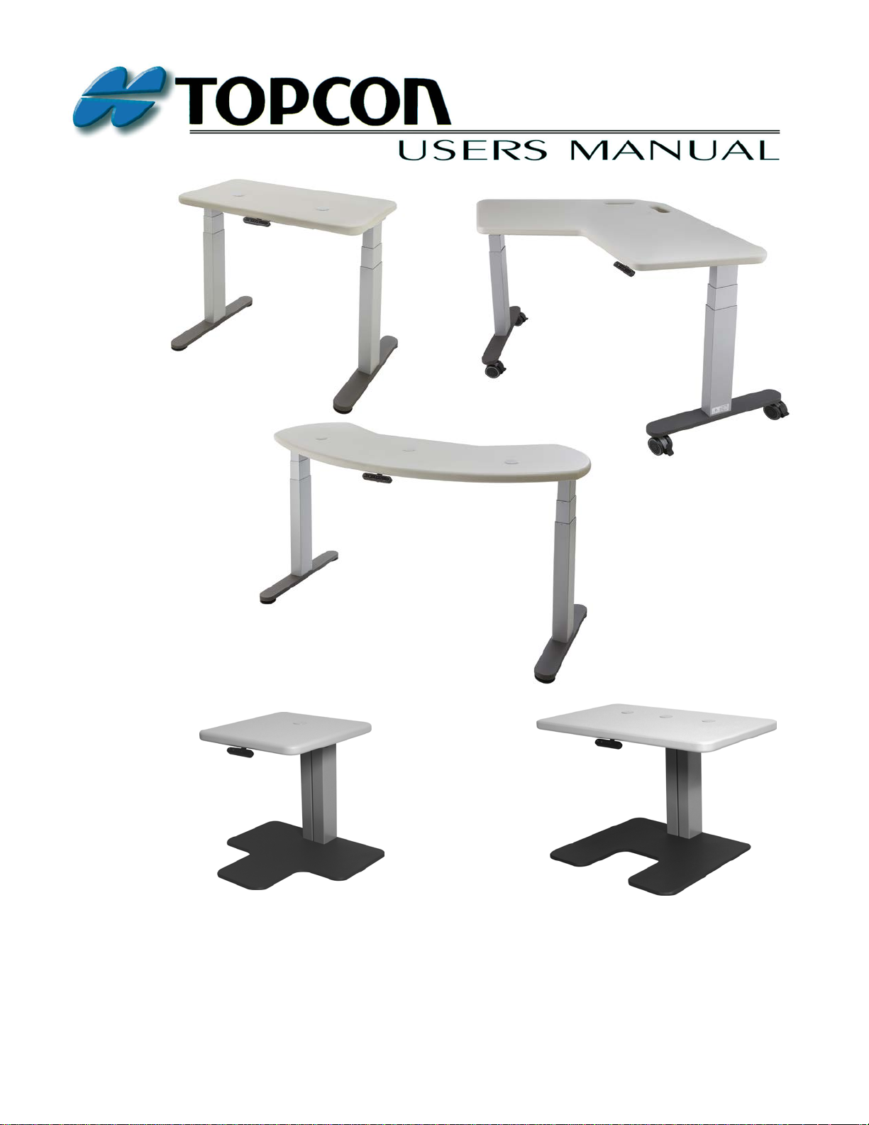
INSTRUMENT TABLES
AIT-250W, AIT-350W, AIT-650
AIT-W1 & AIT-W2
Page 2

WARNING: The installation of the AIT Table shall only be performed by a
qualified technician.
!
WARNING: All service and repairs shall be performed by a qualified technician.
!
WARNING: All replacement parts or optional equipment shall be genuine Topcon
parts. Contact Topcon or your dealer for those items.
!
WARNING: The AIT Table is designed for use with TOPCON equipment.
If any other equipment is used, it shall meet the same certifications.
!
INTRODUCTION
Thank you for purchasing the TOPCON AIT Table.
This User’s Manual covers models AIT-250W, AIT-350W, AIT-650, AIT-W1, and AIT-W2.
The primary difference between these models is the shape of the top and floorplate.
The AIT Table is a state-of-the-art table that provides the ultimate Ophthalmic and Optometric instrument
delivery. The unit is i ntended to hold the diagnostic instruments and to faci litate the proper adjust ments for
the operator and the patient.
Please carefully read this user’s manual to get the best system performance, and place the manual in a
convenient location for future reference.
PRECAUTIONS
1. Installation. Never position the unit where it will be exposed to moisture, direct sunlight, dust, salty air,
chemical storage areas, excessive temperature or humidity. Install the unit in a stable place, free of
uneven floors, vibration and shock.
2. Prior to Operation. Always check that all the cords are properly connected.
3. Operation. Take the proper steps to stop the unit ( leaving the patient in a safe condition) if anything is
found wrong with the unit.
4. After Operation. Never hold and pull the connecting cord for disconnecting plugs. Excessive force may
be applied and cause damage to the inside connections. If the unit has not been used for a long period of
time, check the operation and safety features before using it again.
SAFETY CONCERNS
The AIT Table conforms to UL 60950-1, CSA-22.2 No. 60950-1, and IEC 60950-1. Any of the defined
optional equipment can be added to the AIT Table without any additional safety hazards being introduced
and there is no disposal of any waste products associated with the AIT Table.
2025001032 Revision L, 10/16
Page 3

TABLE OF CONTENTS
1. NOMENCLATURE .................................................................................................................... 1
1.1 AIT-250W/350W/650 Instrument Table Main Components ........................................... 1
1.2 AIT-W1/W2 Instrument Table Main Components ........................................................... 2
2. PERFORMANCE AND SPECIFICATIONS ........................................................................... 3
2.1 Symbols found on the AIT Tables ...................................................................................... 8
3. ASSEMBLY - FOR AIT-250W/350W/650 ONLY ................................................................... 9
3.1 Tools ...................................................................................................................................... 9
3.2 Table System ......................................................................................................................... 9
4. ASSEMBLY - FOR AIT-W1/W2 ONLY ................................................................................ 15
4.1 Table System ....................................................................................................................... 15
5. INSTALLING INSTRUMENTS .............................................................................................. 16
5.1 General Instrument Installation ....................................................................................... 16
5.2 Computer System (Where Applicable) ............................................................................. 16
5.3 Power Up ............................................................................................................................. 16
6. SYSTEM OPERATION............................................................................................................ 17
6.1 Up/Down Buttons ............................................................................................................... 17
6.2 Storage (Memory) Button .................................................................................................. 17
6.3 Position Buttons .................................................................................................................. 17
6.4 Display ................................................................................................................................. 17
6.5 Anti-CollisionTM Safety Feature ........................................................................................ 18
6.6 System Initialization (Optional) ........................................................................................ 18
7. ADJUSTMENTS ....................................................................................................................... 18
8. MAINTENANCE ....................................................................................................................... 18
9. TROUBLESHOOTING ............................................................................................................ 19
2025001032 Revision L, 10/16
Page 4
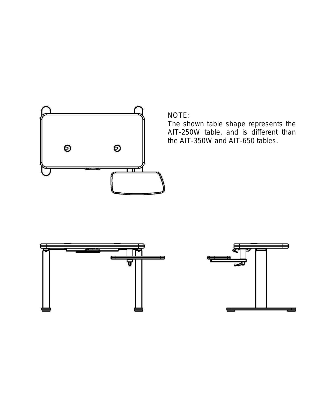
1. NOMENCLATURE
NOTE:
Main Tabletop
Keyboard Table
Table
Keyboard
Feet with Glides
Table
1.1 AIT-250W/350W/650 Instrument Table Main Components
(AIT-250W Model Shown with Keyboard Shelf Assembly, which is optional on some models)
2025001032 Revision L, 10/16 1
Figure 1.1 shows the primary features and key components of the AIT-250W/350W/650 Table.
Use the figure as a reference. Other components of the AIT System are defined in their
Service Manual.
The shown table shape represents the
AIT-250W table, and is different than
the AIT-350W and AIT-650 tables .
Lock Handle
Leg
Figure 1.1: AIT-250W/350W/650 Table System
Leg
Page 5
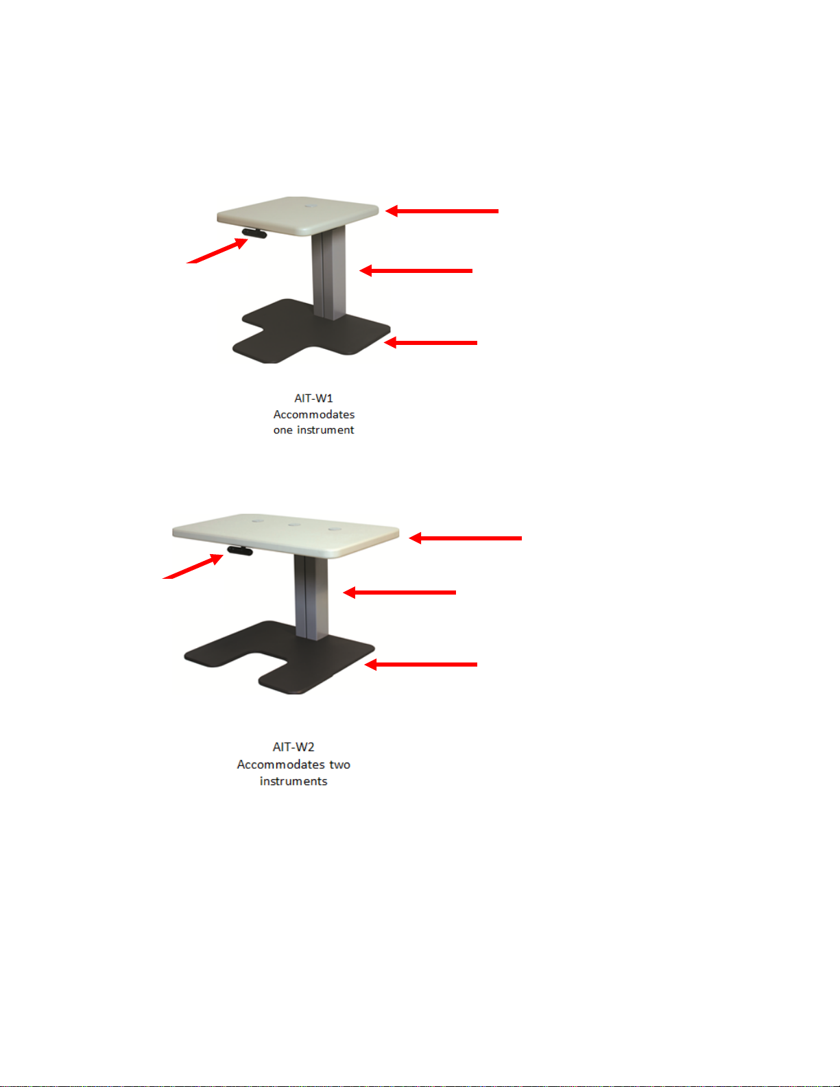
1.2 AIT-W1/W2 Instrument Table Main Components
Floorplate
Floorplate
Table Lifts
Table Lifts
Tabletop
Tabletop
Desk Switch
Desk Switch
Figure 1.2 shows the primary features and key components of the AIT-W1/W2 Table.
Use the figure as a reference. Other components of the AIT System are defined in their
Service Manual.
Figure 1.2: AIT-W1/W2 Table S ystem
(with Control Unit under tabletop)
(with Control Unit under tabletop)
2 2025001032 Revision L, 10/16
Page 6

2. Perform ance and Specifications
Desk System
• Overall Size: AIT-250W - 36 inch x 24 inch x 29 inch
(914 mm x 610 mm x 737 mm)
AIT-350W - 59 inch x 27 inch x 29 inch
(1499 mm x 686 mm x 737 mm)
AIT-650 - 58 inch x 30 inch x 29 inch
(1473 mm x 762 mm x 737 mm)
AIT-W1 - 27 inch x 24 inch x 29 inch
(686 mm x 610 mm x 737 mm)
AIT-W2 - 36 inch x 24 inch x 29 inch
(914 mm x 610 mm x 737 mm)
• Table Height: 23 - 49 inch (584 mm – 1245 mm)
• Duty Cycle: 2min / 18min
• Type of Protection: Class 1 protection (for 120VAC)
(Against Electrical Shock) Class 2 protection (for 230VAC)
• Ingress of Water Protection: Ordinary protection (IPX0)
• AP or APG: Not AP or APG equipment
Table Lift
• Load Range: 0 to 300 lbs. (0 to 136 kg)
• Vertical Range: 26.0 inch (660 mm)
US Versions: 120 VAC (± 10%), 6.0 A, 60 Hz
Non-US Versions: 230 VAC (± 10%), 2.5 A, 50 Hz
• Nominal Speed: up to 1.5 inch/sec (38.1 mm/sec)
KeyboardArm
• Load Range: 0 to 10 lbs. (0.0 to 4.5 kg)
• Horizontal Range: 180 degrees
Electrical
• Voltage, Current, Frequency:
Weight
• Net Weight: AIT-250W - 103 lbs. (46.7 kg)
AIT-350W - 113 lbs. (51.3 kg)
AIT-650 - 115 lbs. (52.2 kg)
AIT-W1 - 217 lbs. (98.4 kg)
AIT-W2 - 218 lbs. (98.9 kg)
Environmental Operating Conditions
• Ambient Temperature Range: 50 to 104 Degrees F (10 to 40 Degrees C)
• Relative Humidity Range: 30 to 75%
• Atmospheric Pressure Range: 10.1 to 15.4 psi (700 to 1060 kPa)
Environmental Storage/Transportation Conditions
• Ambient Temperature Range: -20 to 130 Degrees F (-23 to 54 Degrees C)
• Relative Humidity Range: 30 to 95%
• Atmospheric Pressure Range: 10.1 to 15.4 psi (700 to 1060 kPa)
• Acceptable Storage Time
(in operating environment): 5 years
(in extreme environment): 20 days
2025001032 Revision L, 10/16 3
Page 7
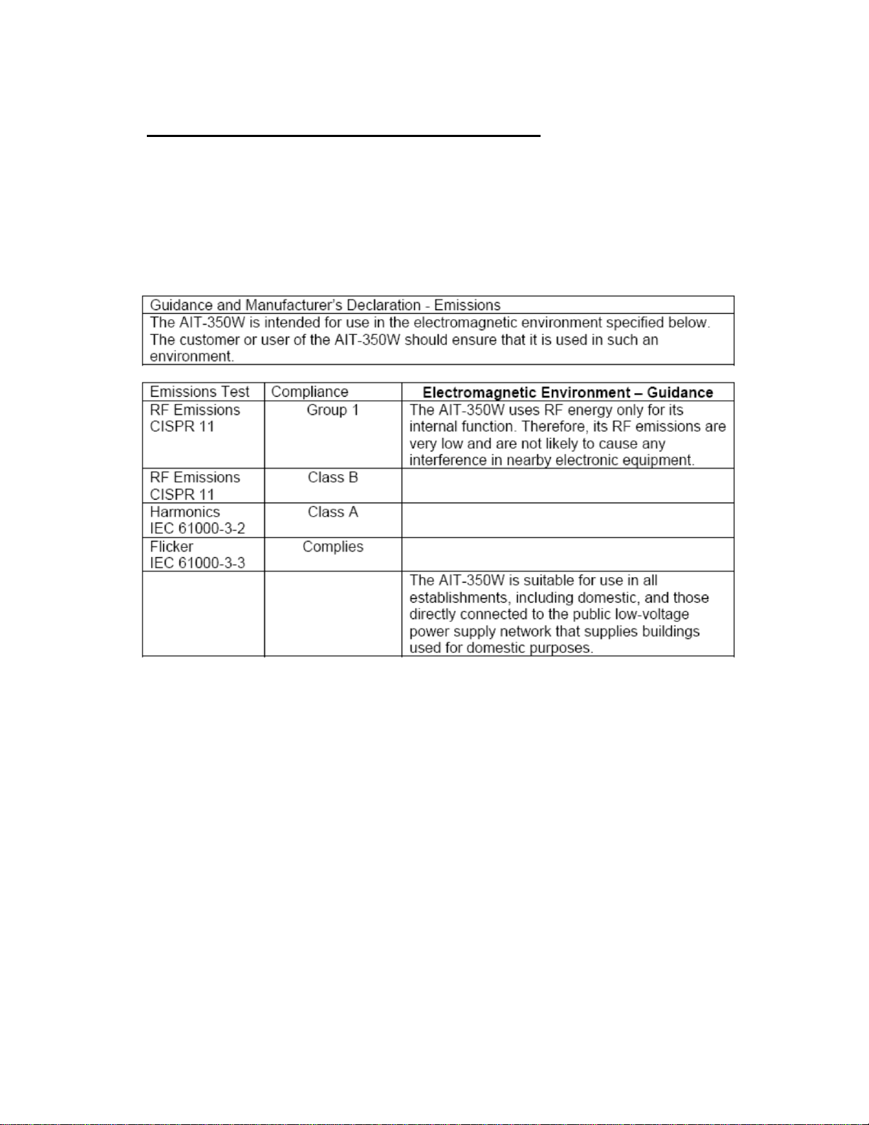
Table 1: Guidance and Manufacturer’s Declarat i on – Emissions
Electromagnetic Environment – Emissions Conditions
Guidance in accordance of Em issions Tes t for all AIT-250W / 350W / 650 / W1 / W2 tables are
listed in Table 1 below:
All Equipment and Systems
4 2025001032 Revision L, 10/16
Page 8

Table 2: Guidance and Manufacturer’s Declaration – Immunity
Electromagnetic Environment – Immunity Conditions
Guidance in accordance of Immunity Test for all AIT-250W / 350W / 650 / W1 / W2 tables are
listed in Table 2 below:
All Equipment and Systems
2025001032 Revision L, 10/16 5
Page 9

Table 3: Guidance and Manufacturer’s Declaration – Emissions
Guidance in accordance of Im munity Test for non-life-supporting AIT-250W / 350W / 650 / W1
/ W2 tables is listed in Table 3 below:
Equipment and Systems that are NOT Life-supporting
6 2025001032 Revision L, 10/16
Page 10

Table 4: Recommended Separation Distances between portable and mobile RF
Electromagnetic Environment – Separation Conditions
Recommended separation distances to prevent electromagnetic interference for AIT-250W /
350W / 650 / W1 / W2 tables are listed in Table 4 below:
Communications equipment and the AIT-350 Equipment and Systems
that are NOT Life-supporting
2025001032 Revision L, 10/16 7
Page 11

2.1 Symbols foun d on the AIT Tables
Ground Symbol
!
ATTENT ION: Inform ation provided in manual
Alternating Current Symbol
Table Mounted Symbols:
Store Button (Program)
Position Buttons
UP: Table Motion Control Symbol
DOWN: T able Motion Control Symbol
Shipping Box Mounted Symbols:
Temperatur e Range for Storage/Tr ansportation
Humidity Range for Storage/Tra nsportation
%
S
1, 2, 3,
and 4
∙, ∙∙, ∙∙∙
8 2025001032 Revision L, 10/16
Page 12

3. ASSEMBLY - FOR AIT-250W/350W/650 ONLY
3.1 Tools
Use the following tools to assemble the Topcon AIT Table:
1. 4 mm and 5 mm hex wrenches.
2. Phillips Screw Driver
3.2 Table System
NOTE: AIT-250W Table will be used in figures as assembly example.
1. Unpack the AIT Table and allow the unit to come to room temperature. Use Figure 1.1 to identify the
main components for all assembly steps.
Note: some models may not contain the Keyboard Shelf Assembly or Casters.
Figure 3.1: Unpack AIT Bo x.
2. Lift t he AIT Table (2 people required for larger tabletop) by grasping the main tabletop and gently
place it upside down on a padded and clean floor surface.
Figure 3.2: Gently Place Table top Upside Down.
2025001032 Revision L, 10/16 9
Page 13

3. Carefully remove the plastic wrapping from the AIT assembly using a utility knife or cutter, without
Components should include:
damaging any paints or components.
Figure 3.3: Carefully Remove AIT Plastic Wrapping.
4. Remove manual and store it for assembly reference and future information. Open accessory box
using utility knife or cutter, and remove components from the box.
- Leg Co lumn (QTY: 2)
- Foot Base with 2 glides (QTY: 2)
- M6 X 20MM Screws ( QTY: 8)
- M6 X 40MM Screws (QTY: 8)
- 2 Allen Keys
- Outlet Strip
Figure 3.4: Remove Components from Accessory Box.
10 2025001032 Revision L, 10/16
Page 14

5. Remove the four (4) M8 screws and four (4) M8 lock washers from the table plate bracket. Leave the
grounding screw remain attached to the bracket. Repeat for the other bracket.
Figure 3.5: Remove Fasteners from Table Plate Brackets.
6. Remove P-clamp from the plate.
Place a motorized table leg column on its side at an incline, with its t op interface (to the bracket)
upwards. Place a padding/weight under the top portion, and another weight (such as stack of papers)
on the floor at the leg base (to prevent the leg f rom sliding downwards). T ilt the bracket to face up,
and secure the leg column onto the bracket, using the shorter four (4) M6X20 screws. Align the holes
in the bracket with the ones in the leg, as shown in the second picture below.
Make sure that the leg is oriented with its cable facing inward towards the control box, and that the
leg is securely fastened on the bracket.
Repeat above step for the other bracket and leg.
Figure 3.6: Install Brackets onto Both Legs.
7. Put the table bracket down onto the tabletop. Re-attach the table bracket onto the top using the
previous M8 screws and lock washers. Repeat this step for the other bracket and leg.
2025001032 Revision L, 10/16 11
Page 15

Figure 3.7: Install Brackets (with Leg Columns) onto Tabletop.
8. Place a foot onto the end of a leg. Install the longer four (4) M6 X 40 screws through the bracket into
the motorized leg. Tighten securely. Repeat for the other leg.
Figure 3.8: Install Feet Bases onto Leg Columns.
9. Open the clamp next to t he brac ket, t o route the bl ack leg cable through it. Pl ug the leg cable int o the
mating connector of the control unit. Secur e the clamp and the cable onto the table top. Repeat for
the other leg cable.
12 2025001032 Revision L, 10/16
Page 16

Figure 3.9: Clamp and Connect Leg Cable s.
10. Where applicable -
a. AIT-650: Install the Casters Kit to the unit as per the instructions provided with the Casters Kit.
Install the Spectrometer Shelf Assembly (optional) to the unit as per the instructions provided
with the Spectrometer Shelf Assembly.
b. AIT-250W, AIT-350W & AIT-650: Install the Keyboard Shelf Assembly (optional) to the unit as
per the instructions provided with the Keyboard Shelf Assembly.
11. Remove padding from the switch panel, and snap the switch panel onto i ts interfacing metal bracket,
which is mounted just under the table. Ensure that the switch panel is easily accessible. Ensure that
all cables are properly connected.
Figure 3.10: Install Switch Pa ne l .
2025001032 Revision L, 10/16 13
Page 17

12. Carefully turn the t able over so the feet are down and move the table into the desired location i n the
WARNING:
To prevent damage to the unit, lift by the main tabletop. Do not
lift the unit by the curved keyboard top.
!
room. If using glides, adjust them on the feet to achieve a level condition. If using casters, lock them
when table is placed at desired location.
Figure 3.11: Table is now assembled.
13. Plug power cabl e to outlet . Using the switch panel, ope rate the t able up/down to move it into desired
height position setting, using the up/down arrow respectively.
If table reset is needed, perform system initialization procedure in Section 6.6. Mor e functionalities
of the switch panel can be found in System Operation Section 6.
14 2025001032 Revision L, 10/16
Page 18

4. ASSEMBLY - FOR AIT-W1/W2 ONLY
NOTE: Both AIT-W1 and AIT-W2 Tables arrive pre-assembled in shipping box.
4.1 Table System
1. Unpack the AIT-W Table and allow the unit to come to room temperature.
Use Figure 1.2 to identify the main components.
2. Move the table to the desired location in the room by lifting the side of the tabletop.
Place the back of the table close/flush to the wall.
NOTE: At least two people should perform this task.
If moving the table to a far location, a dolly is recommended to be used,
Figure 4.1: Unpacking AIT-W
(AIT-W1 is shown in this Figure)
3. Plug power cable to out let. Using the switch pa nel, operate the table up/ down to move it into desired
height position setting, using the up/down arrow respectively.
If table reset is needed, perform system initialization procedure in Section 6.6.
More functionalities of the switch panel can be found in System Operation Section 6.
Figure 4.2: Operating AIT-W
(AIT-W2 is shown in this Figure)
2025001032 Revision L, 10/16 15
Page 19

5. Installing Instruments
WARNING: Check all power cords and electrical connections for damage prior to
powering up the system.
!
The instruments that connect to the AIT Table must be mounted and configured properly before
operation. The AIT Tabl e was designed for Topcon i nstruments. Consequently, adj ustments may
be required for other brands of instruments and/or tools.
5.1 General Instrument Installation
1. Lift and place the diagnostic inst ruments onto the main tabletop. Adjust the level of
the instrument. Route the power cable down through one of the wire grommets in the
table and if required into the wire channel. Plug into the power strip supplied with
the table or a facility power source.
5.2 Computer System (Wh er e Applicable)
1. P lace the CPU into the CP U bracket assembly (optional) if equipped. Plug into the
power strip supplied with the table or a facility power source.
2. P lace the red uced-size keyboard and mouse on the pivoting keyboard shelf. Pivot the
keyboard by loosening the locking knob (on the underside), and re-tightening it once
in the desired position. Cabling may be routed through the wire channel(s)
underneath the table. Connect all computer-related cables and raise the table to
ensure that enough cable slack is provided to allow a service loop to the CPU. If the
cables are too short, extension cables may be required.
5.3 Power Up
1. Plug in the power cord, and observe the initial height displayed (inches for 120 VAC
2. Turn ON all the instruments placed on table. Check the functionality of all the
3. Once satisfied with the connections of all the instruments, see the next section, SYSTEM
units and cm for 230 VAC units). Refer to the operation section of this document for the
details.
components. Refer to the documentation supplied with each individual instrument for
operation details.
OPERATION, for details using the system.
16 2025001032 Revision L, 10/16
Page 20

Up/Down Buttons
Display
Position Buttons
Storage Button
6. SYSTEM OPERATION
Each of the desk system switch panel control buttons performs a specific function. Ensure that the
table system is properly plugged in. See Section 5.3.
Those functions and additional information are identified in the following paragraphs. See Figure 6.1
for an illustration of the control panel.
Figure 6.1: Desk System Switch Panel
6.1 Up/Down Buttons
The UP arrow drives the synchronized legs UP. The down arrow drives the synchronized legs
DOWN.
6.2 Storage (Memory) Button
The storage (S) button is used to program a desired table height in memory.
6.3 Position Buttons
The position buttons (∙, ∙∙, and ∙∙∙) which denote numbering of (1, 2, and 3) respectively,
allow a particular height to be stored in memory so that a user can return to the same position
easily. Pressing and holding the button will move the table to that pre-programmed position.
To program a position in memory, move the table to the desired height, press and hold the
storage (S) button until an “S” appear on the display, and then press on a specific position
button to store the height memory (the button number will appear on the display next to the
S). The height is now recorded.
6.4 Display
The Display shows the relative height of the table. 120 VAC units will display the height in
inches. 230 VAC units will display the height in centimeters. The display will turn off after
some time if no buttons are pressed.
2025001032 Revision L, 10/16 17
Page 21

6.5 Anti-CollisionTM Safety Feature
WARNING:
All service and repairs shall be performed by a qualified technician.
!
Anti-collision function is included in the table system for safety feature. If a “collision” with
solid object at any area under/above the table should occur while the tabletop is moving
down/up respectively, the table system will stop operation, start to run in the opposite
direction (~2in), and then make a complete stop. Remove the obstacle, and operate table
normally.
CAUTION: Safety feature may not activate if t he coll isi on occurs durin g initialization phases
(see Section 4.6), or within the first 1000msec or after the control unit button has been
released, or if the collision pressure is very low or with a soft object.
6.6 System Initialization (Optional)
NOTE: All new units are provided with complete initialized systems. Use this procedure only
for syncing or leg replacements.
To initialize Table system, press and hold the down button once or twice, and holding it down.
It will stop when reached the bottom, and then automatically run ~0.2in up/down again.
ONLY release the down button when movement has stopped completely. DO NOT place any
obstructions under the table during initialization of control unit. If button is released before
sequence completed, initialization process has been interrupted and must be restarted. See
Section 4.5.
7. ADJUSTMENTS
No periodic adjustments of the desk system are required. If problems arise, please refer to Section 9:
TROUBLE SHOOTING.
The instruments used with the desk system may require periodic adjustments and/or calibrations.
Refer to the documentation supplied with the appropriate instrument(s) for details.
8. MAINTENANCE
There are no periodic main tenance requirements for the AIT Table. However periodic checks of all
the functions, and power cords should be performed every six months. For operational detail, please
refer to Section 6: SYSTEM OPERATION.
If problems arise, please refer to Section 9: TROUBLESHOOTING.
It is recommended that the exterior surfaces of the AIT Table be cleaned with a mild soap, water, and
clean damp cloth to maintain a like-new appearance.
Cleaning shall be performed at least every six months.
18 2025001032 Revision L, 10/16
Page 22

WARNING: All service and repairs shall be performed by a qualified technician.
9. TROUBLESHOOTING
!
If the AIT Table does not function properly, check the following points before asking for assistance.
Disconnect the main plug before any servicing is performed.
1. Read this User Manual to verify the AIT Table functions. Full part descriptions and diagnostic
information is provided in the Service Manual (supplied to dealers only).
2. Check to see that all cords and / or cables are securely connected and that the height is displayed.
3. Check all diagnostic instruments with a facility power source to verify their proper functions.
4. If problems persist, contact your dealer or Topcon directly.
2025001032 Revision L, 10/16 19
Page 23

If problems persist, call your dealer or Topcon for assistance.
Topcon Medical Syste ms, Inc.
111 Bauer Drive
Oakland, NJ 07436
800-223-1130
www.topconmedical.com
Please provide the following information when contacting us with questions about
this instrument:
• Model Name: AIT-250W / AIT-350W / AIT-650 / AIT-W1 / AIT-W2
• Voltage Version: 120V / 240V
• Serial Number: This is provided in the product rating label on the
back of the base assembly
• Period of use: Please inform us of its date of purchase
• Defective condition: Please provide us with as much details as possible
Topcon AIT Instrument Table
USER MANUAL
2016 version (2025001032 Revision L)
Date of issue: October 7, 2016
Copyright © 2008 – 2016 Topcon Medical Systems, Inc. All rights reserved.
 Loading...