

Page 1
INSTRUCTION MANUAL
AUTO CHART PROJECTOR
ACP-8
Page 2

INTRODUCTION
Thank you for purc hasing the TOPCON ACP-8 Auto Chart
Projector.
(To get the best use this instrument, please carefully read
these instructions and keep this Instruction Manual in a convenient location for future reference.)
This text outlines the ACP-8 Auto Chart Projector and descri bes basic
operations, trouble sho oti ng, ch ec ki ng, mai nte nan ce and clean in g.
To encourage the safe, efficient use of this instrument and to prevent
danger to the operator and others, we suggest you carefully read the
"Displays for Safe Use" and the "Safety Cautions".
Again, please k eep this Instruction Manua l in a convenient locati on for
future reference.
Precautions
• This machine is a precisio n instrumen t; install it in a place tha t is set
to the following conditions: temperature (10~40°C), humidity
(30~85%) and atmospheric pressure (70~106KPa). Avoid direct
exposure to sunlight.
• To ensure smooth operation, ins tall the instrument on a lev el surface
free of vibrations. Also, do not place any objects on the instrument.
• Before using the instrument, connect all cables properly.
• Use the specified source voltage. (±10% 50/60Hz ±1kHz)
• When not in use, turn the power off and dust cover on the instrument.
• To ensure a correct readi ng, do not soil the measuring w indow with
finger prints, dust, etc. Also, do not touch the measuring nozzle
except when cleaning.
1
Page 3
DISPLAY FOR SAFE USE
In order to encourage the safe use of this product and prevent any danger to the operator and
others or damage to pr operties , impor tant warnings are plac ed on the produ ct and ins erted in
the instruction manual.
We suggest that everyone und erstand th e meanin g of the fol lowing display s and icons befor e
reading the "Safety Cautions" and text.
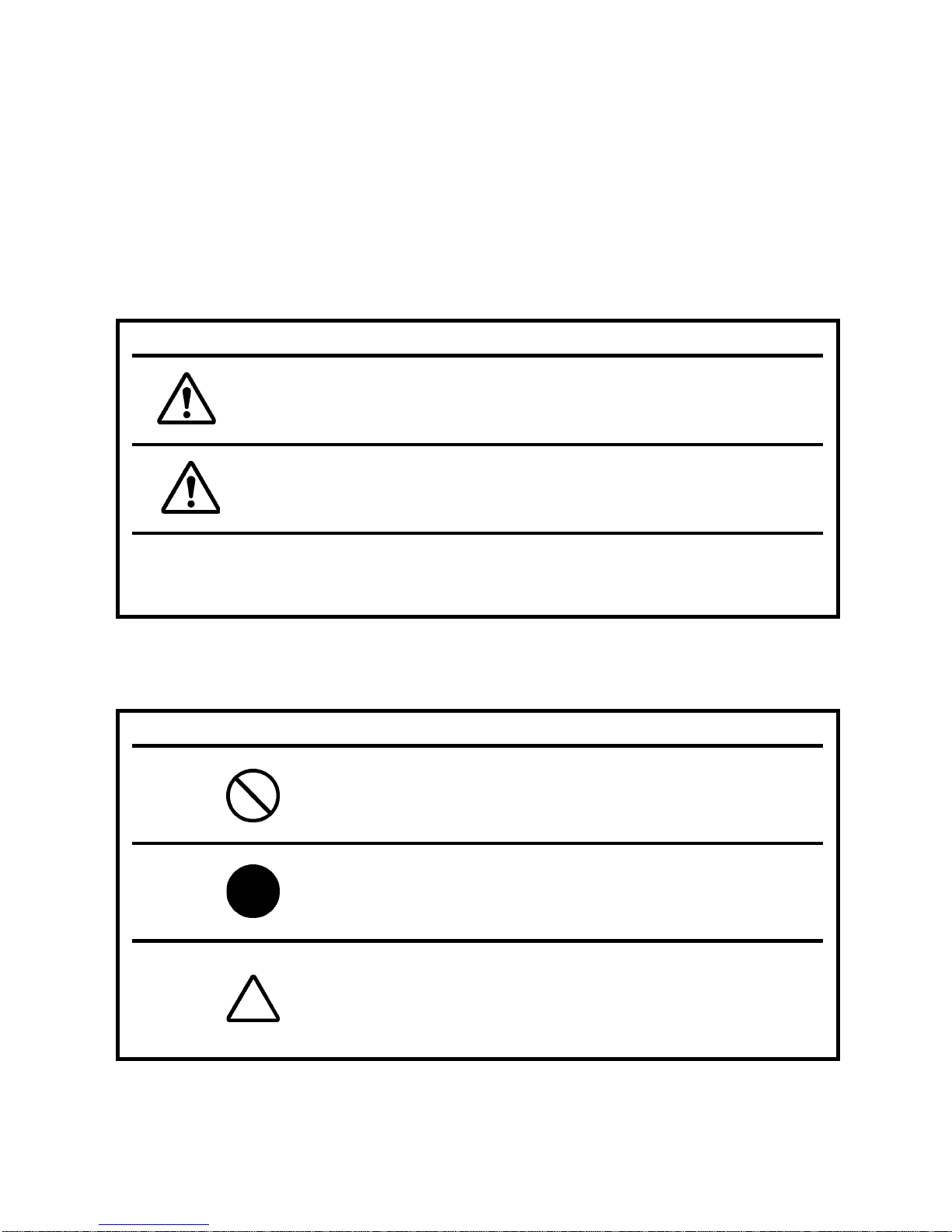
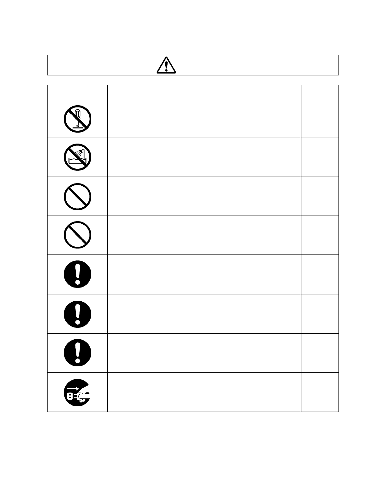
WARNING
DISPLAY MEANING
ICONS
WARNING
CAUTION
• Injury refers to cuts, bruises, sprains, fractures, burn, electric shock, etc.
• Physical damage refers to extensive damage to buildings or equipment and
furniture.
ICONS MEANING
Ignoring or dis regarding this disp lay may lead to dea th
or serious injury.
Ignoring or disregarding this display may
lead to personal injury or physical damage.
This indicates Prohibition.
Specific content is expressed with words or an icon
either inserted in the icon itself or located next to the
icon.
2
This indicates Mandatory Action.
Specific content is expressed with words or an icon
either inserted in the icon itself or located next to the
icon.
This icon indicates Hazard Alerting (Warning).
Prohibition.
Specific content is expressed with words or an icon
either inserted in the icon itself or located next to the
icon.
Page 4
SAFETY CAUTIONS
Icons Prevention item Page
Do not break down, modify or repair the equipment.
Doing so can cause electric shock. Request a repair from
your dealer.
WARNING
20
To pr event an electric shock hazard, do not allow water or
other foreign matter to enter into the instrument.
To av oid fire and el ectric shock in the case of tumbl ing, do
not place a cup or vessel containing water/fluid on the
instrument.
To avoid electric shock, do not insert objects or metals
through the vent holes or gaps or place them inside the
machine body.
Connect the power plug to a three-prong properly grounded
AC socket with an earth. If it is connected to a socket that is
not grounded, it c an cause a fire an d electric sh ock due to
leakage.
Unplug the power cable b efore removing the fuse cov er to
replace the fuse. R emoving the fuse cover w ith the power
cable plugged in can cause electric shock. Do not install the
power cord on the body with the fuse cover removed.
--
--
--
11
25
Use only attached fuses (For 100, 120V range: T-1.6A, 250V
For 220, 230, 240V range: T-1A, 250V). Using other fuses may
cause a fire in the event that the instrument fails.
Should any anomaly, such as smoke, occur, immediately
switch OFF the power source and unplug the power cable.
Continued use while ignoring the condition may cause a
fire. Contact your dealer for repair.
25
--
3
Page 5
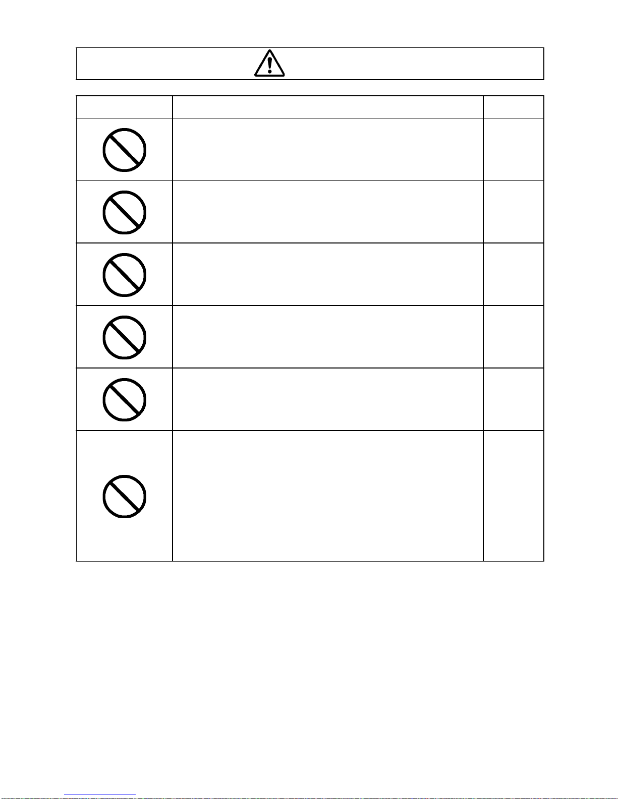
CAUTION
Icons Prevention item Page
Do not tilt the device or pla ce it in an uns table plac e. O the rwise, the device may topple over, drop or cause injury.
Handling the power plug with wet hands can ca use electri c
shock.
To avoid electric shock, unplug the power cable when
replacing the projection lamp.
Do not replace the projection lamp immediately after turning
off the light. Otherwise, you mig ht get burnt by the hot temperature of the lamp.
When this instrument is not used for a long time, remove
the batteries from the remote controller.
11
11
23
23
11
This instrument has been tested (with 120V/230V) and
found to comply with IEC60601-1-2: 1993.
This instrument radiates radio frequency energy within standard and may affect other devices in vicinity.
If you have found out by turn ing on/o ff the instrume nt that it
affects other devices, it is recommended to change the
direction, keep a prop er distance against other devices or
change the outlet.
If you have a question, consult with the selling agent.
--
4
Page 6

USAGE AND MAINTENANCE
PURPOSE
This Auto Chart Projector "ACP-8" is a precision electrical device for medical use that
must be used under the instruction of a doctor.
FUNCTION AND INTENDED APPLICATION
This product is desi gned to project the eye test chart for v isual acuity examination to th e
screen. In order to control the eye test chart, controller is available.
USER MAINTENANCE
To maintain the safety and performance of the equipment, never attempt to do maintenance on your own. Ask our service personnel for repairs except for the items specifie d
here which can be maintained by the user. For details, follow the instructions.
FUSE REPLACEMENT
The primary fuses for the main body may be replaced by a non-trained service technician.
For details, refer to "Replacing the Fuse" on page 25.
LAMP REPLACEMENT
The projection l amp c an be r e pla ce d. Re fer to the i nst ru ctions in "Replaci ng the Proj ec tio n
Lamp" on page 23 for details.
ESCAPE CLAUSE
• TOPCON shall not take any responsibility for damage due to fire, earthquakes, actions
by a third party or other accidents, or the negligence a nd misuse of the user and use
under unusual conditions.
• TOPCON shall not take any resp onsibil ity for dama ge deriv ed from th e inability to use
this equipment, such as a loss of business profit and suspension of business.
• TOPCON shall not take any responsibility for damage caused by operations other than
those described in this Instruction Manual.
• Diagnoses shall be made on the responsibility of pertaining doctors and TOPCON shall
not take any responsibility for the results of such diagnoses.
5
Page 7
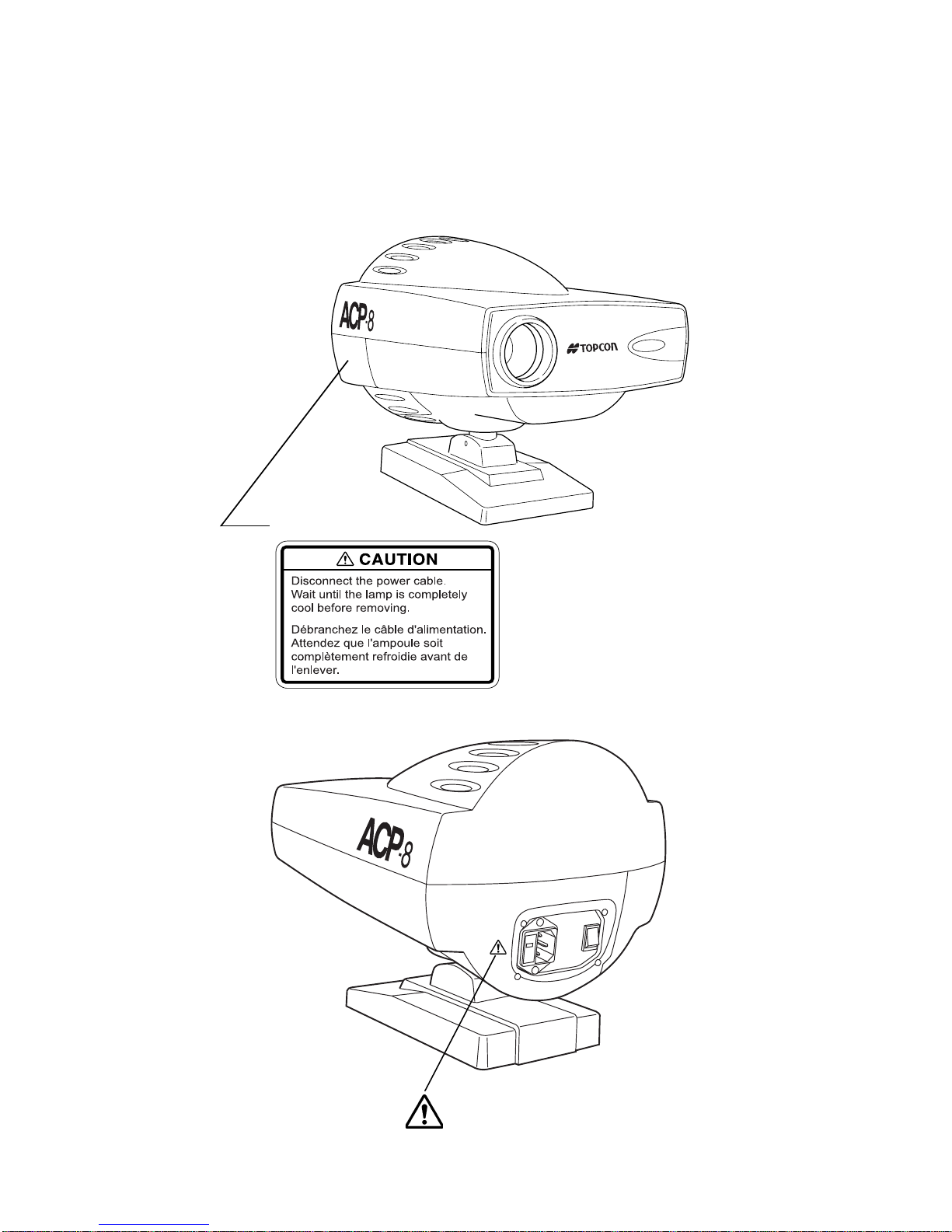
WARNING INDICATIONS AND POSITIONS
To ensure the safe usage of this equipment, precaution indications are provided.
Abide by the following warning instructions. If any of the following labels are missing,
please contact us at the address printed on the back cover of this manual.
Inner of lamp cover
6
See P.25
Page 8

CONTENT
INTRODUCTION ..................................................................................... 1
DISPLAY FOR SAFE USE ...................................................................... 2
SAFETY CAUTIONS ............................................................................... 3
USAGE AND MAINTENANCE ................................................................ 5
ESCAPE CLAUSE ... ...... ....... ...... ....... ...................................... ....... ...... ... 5
WARNING INDICATIONS AND POSITIONS .......................................... 6
Names of parts
Names of parts on the main body ............................................................ 8
Remote controller .................................................................................... 9
Standard accessorie s ........... ...... ....... ...... ....... ...... ....... .......................... 10
Operation procedures
Preparations .......................................................................................... 11
Usage guide
Operating the random access controller ................................................ 15
Using the program functions . ...... ....... ...... ....... ...... ................................. 16
Using charts for measuring binocular visual functions ........................... 18
Troubleshooting
Operating procedures for troubleshooting ............................................. 20
Chart
.......................... .............................................. ....................................... 21
Care and check
Daily Maintenance ................................................................................. 23
Changing the channel setting of the remote controller .......................... 26
Maintenance .......................................................................................... 28
Reference
Optional Accessories ............................................................................. 29
Specifications ........................................... ............................................. . 29
7
Page 9
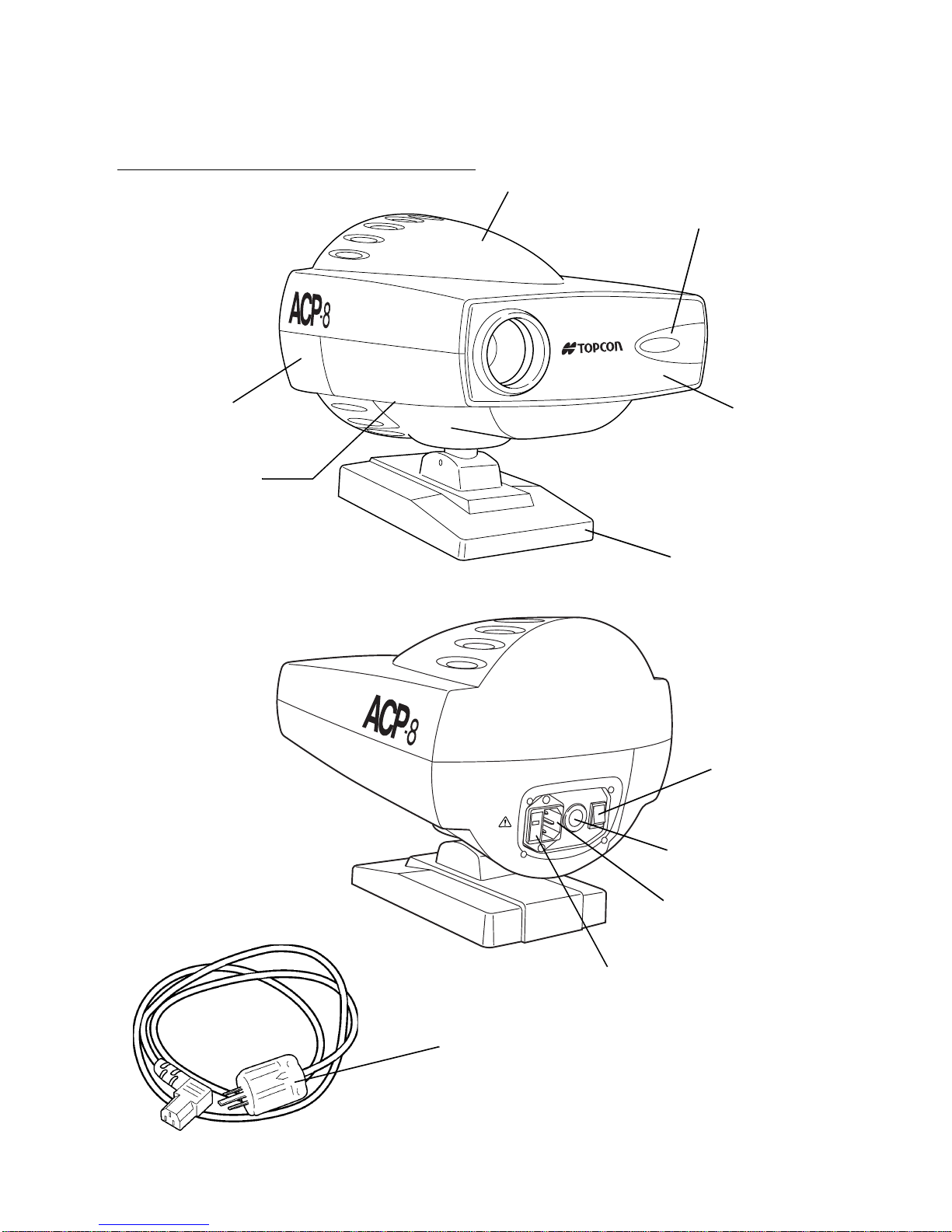
Names of parts
t
Names of parts on the main body
Top cover
Sensor
Lamp cover
Barrel screw
(Some types do not have i
Base
in the standard kit.)
Power switch
RS232C connector
(only MC type)
Front pa nel
8
Names of parts
Power socket
Fuse holder
Voltage selector
Power plug
Page 10
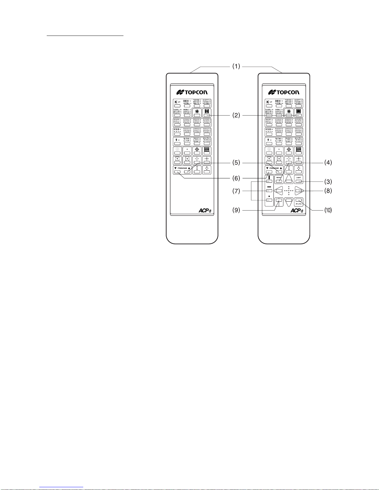
Remote controller
1 Light emitter
2 Chart switch
3Light switch
4Reset switch (*)
5 Forward switch (*)
6 Back switch (*)
7 Mask selector
8 Mask transfer switch
9R&G switch
10 Program switch
* These switches are used
when activating the 'program' mode.
E type EM type
(Example : A type chart)
9
Names of parts
Page 11
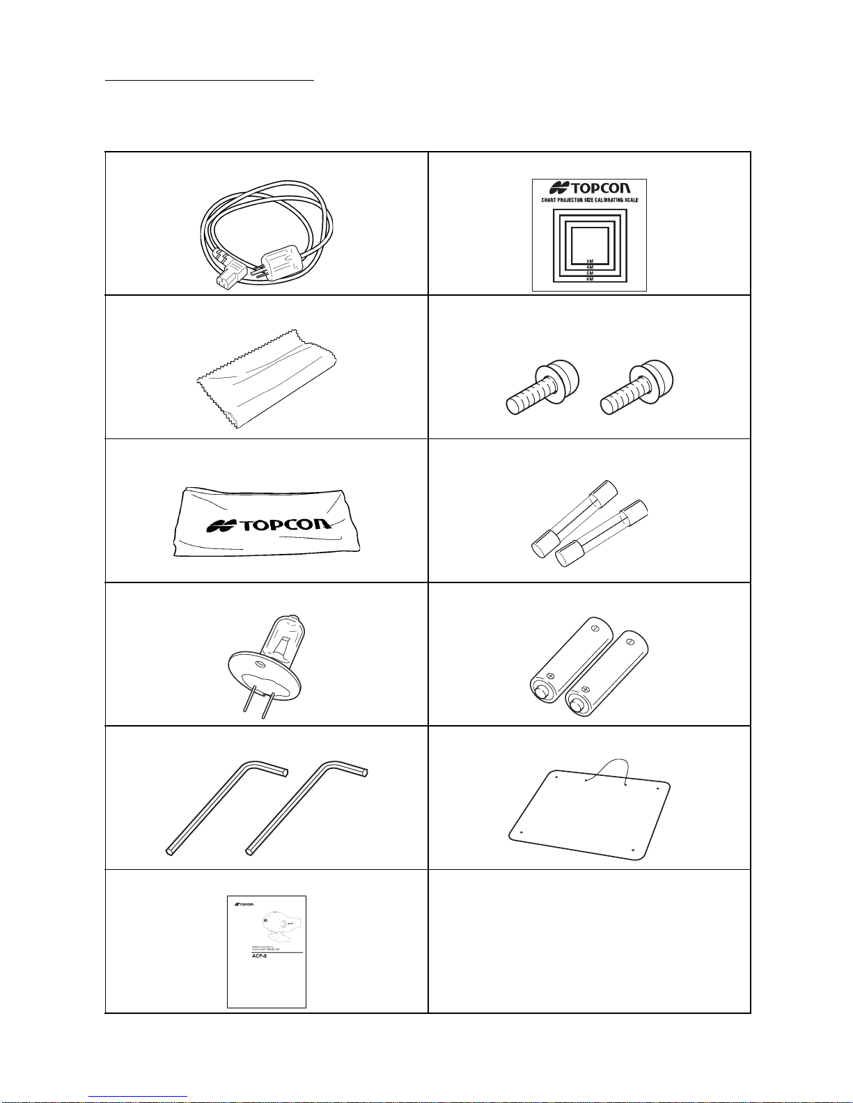
Standard accessories
The following a re th e s tandard accessories. Pleas e c he ck i f they are all inclu ded .( ) refe rs
to the number of items.
Power cord (1) Calibration card (1)
Silicone cloth (1) Attachment screws (2)
Not included in the types without base.
Dust cover (1) Spare fuse (2)
Spare lamp (1) Dry battery (UM-3) (2)
Hexagonal wrench for focus adjustment (2) Screen (1)
Instruction manual (1)
10
Names of parts
Page 12
Operation procedures
Preparations
Caution
Warning
Caution
Caution
Do not tilt the dev ice or place it in an unstabl e place. Otherwise,
the device may topple over, drop or cause injury.
Connect the power plug to a three-prong p roperly gr ounded AC
socket with an earth. If it is connected to a socket that is not
grounded, it can cause a fire and electric shock due to leakage.
Handling the power plug with wet hands can cause electric shock.
When this ins trument is not use d for a long time , remove t he batteries from the remote controller.
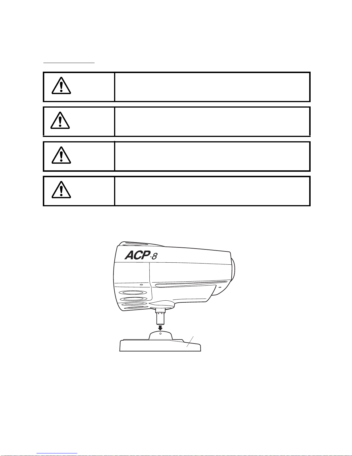
1 Place the instrument at the same level as the person to be measured.
When installing by using the base, insert the shaft of the instrument into the base as
illustrated. (This method is same when using the stand or wall mount.)
2 Turn the power switch 'off'.
3 When more than two instrumen ts are installed in close proxim ity to each oth er, it is
necessary to set the channel by the DIP switches of the body and the signal channel
switches of the remote controller in order to avoid interference.(Up to four instru-
ments may be installed at the same location)
* At the time of shipment, the instrument is set at channel 1.
* To c hange the cha nnel, s ee "C hang ing the chann el se tting o f the re mote c ontrolle r"
on page 26.
Base (Some types do not have
it in the standard kit.)
11
Operation procedures
Page 13

4 Insert the connecto r of the powe r cord in to the power socket on th e body and insert
the power supply plug into the outlet.
5 Turn the power switch 'on'.
6 Remove the battery cover from the back of the remote controller.
7 Insert the dry batteries into the remote c ontroller a s illustrat ed and repl ace the bat-
tery cover.
(How to insert batteries)
8 Adjust the position of the body so that the projected light is centered on the screen.
12
Operation procedures
Page 14

For E, EM, MC type
9 Loosen the barrel screw
about a half of a turn with
the attached hexagonal
wrench.
Move the knob in the arrow
direction so that the projec-
tion on the screen is sharp
and clear. For proper cali-
bration, the projection of the
chart which has 0.1 (or 20/
200) visual acuity should
contact the inner side of one
of the scales on the cal ibra-
tion card which correspon-
dis to the desired refracting distance.
Barrel screw Knob
10 If the size does not match the respectiv e refracting dis tance scale, move the instr u-
ment either toward or away item the screen and then repeat items 9 above.
11 Fix the bar rel screw to complete preparation.
13
Operation procedures
Page 15

For R type (variable focus lens type)
12 Loosen the first lens-barrel screw and the second lens-barrel screw about a half of a
turn.
Move the lens-barrel screw
in the arrow direction with
the hexagonal wrench
inserted.
The first lens-barrel screw:
size
The second lens-barrel
screw: focus
Move the first lens-barrel
screw to roughly fit the size
and move the second lens-
barrel screw to achieve the
focus.
13 Move the first an d second lens-barrel screw for-
ward and/or backward to focus 20/200 (or 0.1)
visual acuity "E" on to the projection screen.
Place the calibration card on the projection
screen. The "E" of the 20 /200 sl ide s hould fi ll an d
just touch the inner sides of the scale which corre-
sponds to the desired refracting distance.
* The variable focus lenses permits the R type to be positioned at the following projec-
tion distances relative to refracing distance:
Refracting Distance Projection Distance
3m 2.90 to 3.70m
4m 3.80 to 4.80m
5m 4.70 to 5.90m
6.1m 5.70 to 7.10m
For example:
At a refracting distance of 5 meters, the R type Au to Chart Pr ojec tor ca n be pos itioned at a distance of 4.70 to 5.90 meters. Withi n this range, th e variable focus
objective lenses can project the properly calibrated image.
14 Fix the bar rel screw to complete preparation.
14
Operation procedures
Page 16

Usage guide
Operating the random access controller
1 Turn the power switch on. The char t will b e reset
to the start position and the lamp will light up.
2 Direct the light emitt er on the remo te contr oller to
the sensor on the projector body or use a wall
with high reflectivi ty to receive the reflected light
on the light emi tter and pr ess each switch b efore
using.
• Switch functions
(1) Chart switch. . . . . . . . . . . .Projects the chart as
indicated on the switch.
(2) Light switch . . . . . . . . . . . .Turns the lamp on/off.
(3) Reset switch. . . . . . . . . . . .Returns to the step 1
chart in the program.
(4) Forward switch. . . . . . . . . .Automatically advances
the step in the program.
(5) Back switch . . . . . . . . . . . .Automatically backs the
step in the program.
(6) Mask selector. . . . . . . . . . .Allows selection of a
mask that is appropriate for the chart. (horizontal
mask, vertical mask, one character mask).
(7) Mask transfer switch . . . . .Moves the mask in the
direction as indicated on the switch. When the mask
moves to the maximum (minimum) indication of a
chart being projected, the next (previous) chart in
the sequence will au tomaticall y appear. Charts can be switched wi thin the same type
of charts.
(8) R&G filter switch . . . . . . . .R&G filter can be applied only for the chart that allows
R&G filtering.
(9) Switch the program P1 with the program P2.
* See P.16 for using the program function.
* When the lamp is turned off, the lamp will light up by pressing either the (1) or (3)-(9)
switches.
* When the mask i s not open, it will automatically be ope n by pressing the (1) chart
switch.
* When the inst rument is not used for 10 mi nutes, it will be automatic ally turned off
(Auto shut-off mechanism)
(4)
(5)
(6)
(8)
Example: A type chart
(1)
(3)
(2)
(7)
(9)
15
Usage guide
Page 17

Using the program functions
1 How to program the measuring procedure
(1) To start programming
Turn the power switch on whi le pressing the reset switch. Rele ase the reset switch
when the buzzer sounds once. The chart will return to the start position, the lamp lights
up and the buzzer sou nds twice. Select either program 1 or 2 by pres sing P1 or P2.
(Buzzer once: P1 initial value, buzzer twice: P2). Press the “^” switch. The buzzer
sounds three times.
(2) Programming the charts
Press the chart s witch or the mask switch ac cording to the measuring p rocedure to
project and press the “^” switch. The buzzer sounds four times and this completes one
step.
* Repeat this to program the procedure. Programming is available for up to 30 steps.
(3) Complet ing the programming
Press the reset switch. This completes the programming.
* Programming 30 steps will automat ically compl ete the function w ith out press ing the
reset switch.
* Turning the power switch off won’t erase the program.
* Follow the steps abov e to start a new prog ram. The for mer program wil l be erased
to start a new program.
16
Usage guide
Page 18

2 Carrying out program-base examinations (Example : A type chart)
• Turn the power switch on.
• The chart at the s tart position will be projected.
• Step 1 chart will be called up.
• Step 1 chart will be projected.
• You can reset to the beginning (step 1) of the p rogrambased examination during an examination.
• Any desired chart can be projected during the course of
a program-based examination.
• Pressing the program up and down switch es can back
up the program at any time. The program can be backed
up as many steps as necessary.
• The chart of the last step will be projected.
• The instrument w ill re turn to t he fir s t (s tep 1) c ha rt i n th e
program-based examination.
17
Usage guide
Page 19

Using charts for measuring binocular visual functions
Chart
Filter
Purpose
Right
eye
Left
eye
Polarized R and G tes
t Binocular balance test Worth four dot test Cross ring test
A, B, *F, *H C type
A, C, F type
Polarizing filters Polarizing filters
Test of binocular refraction and accommodation balance
The right eye is over corrected and the left eye is
under corrected.
type
Test of the final binocular refraction balance
There is a variance of degree
between the right eye and the left
eye.
A, C, F, H B type
type
Red filter f or th e r igh t ey e and
green filter for the left eye
Test of the function of binocular
fusion
In the case where 4 dots are
seen, there will be normal fusion.
The white (bottom) color indicates which eye can see better. If
red is seen mixed with green, the
right and left eyes function at the
same level.
Red filter for the right eye and
green filter for the left eye
Test of the presence and
level of latent heterophoria
Indicates exophoria of 3
prisms.
The left eye is over corrected and the right eye
is under corrected.
The binocular refraction
and accommodation balance are achieved when
the two reds or two
How the charts are viewed
greens are seen at the
same intensity.
How the charts are seen binocularly
Adjust the spherical power to
provide binocular balance.
*The Characters used in the F
and H types are not the same as
those shown above.
If only two targets are seen, the
left eye is suppressed.
If only three green targets are
seen, the right eye is suppressed
If five targets are seen, it indicates that the patient has diplopia.
Indicates esophoria of 2
prisms.
Indicates left eye hyperphoria of 1 prisms.
Indicates left hypophoria of 0.5 prisms.
18
Usage guide
Page 20

Polarized crosshair test Reticle heterophobia
test with a fixation target
Coincidence test Coincidence test Stereo test
A, B, C, F, H type A, B, C, F, H type
A, F, H type
A, C, F type
A, B, C, F, H type
Polarizing filters Polarizing filters Polarizing filters Polarizing filters Polarizing filters
Test of the accommodation balance and heterophobia
Esophoria
Exophoria
Left eye hyperphoria
Left eye hypophoria
Heterephobia which can
not be examined by the
reticle testing is tested.
The right eye has an infixation disparity.
Indicates that the right
eye has an infrafixation
disparity.
Indicates that the right
eye has an suprafixation
disparity.
T est of aniseikonia and vertical heterephobia which
can not be examined by
polarized crosshair test.
Aniseikonia of about 7%
(equivalent to two lines)
A single line indicates
about 3.5%.
Vertical heterophoria
If either line is seen thinner, the eye in question is
suppressed.
Test of aniseikonia and vertical heterephobia which
can not be examined by
polarized crosshair test.
Aniseikonia of about 7%
(equivalent to two lines)
A single line indicates
about 3.5%.
Vertical heterophoria
If either line is seen thinner, the eye in question is
suppressed.
Test the presence of stereoscopy.
Two lines are seen in
fusion to form a single line
image and floated or sunk
against the central circle.
The binoculra parallaxes
is about 13 minutes and
the lower line is seen
floating about 1.1m (when
seen at a distance of 5m
with a PD of 64mm)
If the axis of the polarizing
filter is reversed at the
same time for both eyes
and seen sunk about
2.1m, it is normal.
If the images are slowly
fused, there is still correctable heterophoria.
Verify with another heterophoria test. If it takes
some time until the image
appears to float, the
patient may have an exophoria.
If it takes some time until
the image sinks, the
patient may have an esophoria.
Left eye hypophoria
If either line is seen thinner, the eye in question is
suppressed.
If either is clearly visible,
there is observed suppression with the periphery of the retina in
question.
19
Usage guide
Page 21

Troubleshooting
Operating procedures for troubleshooting
Operating procedures for troubleshooting
Warning
Do not break d own, mod ify or repair the eq uipmen t. Doing so ca n
cause electric shock. Request a repair from your dealer.
Check the items in the fol low ing che ck li st whe n yo u ex perie nc e a pr obl em. W hen the si tuation is not recovered by the indicated action or the problem does not comply with the
description in the "Situation" column in the check list, contact your dealer or the address on
the back cover of this manual.
Check list
Situation Example Action
The projection lamp does
not light with the power
switch on.
• Is the power supply plug
connected to the incoming line source?
• Is the power cord connected?
• Is the fuse blown? See P.25 for fuse replace-
Plug it securely in the outlet. --
Plug it securely in the
power on the main body.
ment.
Reference
page
11
25
The instrument does not
function when the remote
controller switch is
pressed.
When you can't reso lve the proble m after checking al l the items desc ribed above , contact
us at the address shown on the back cover of this instruction manual.
20
Troubleshooting
• Is the lamp burnt out? See P.23 for lamp replace-
ment.
• Are the batteries fresh? Replace the battery. 11
• Is there anything interrupting the light emitter
on the remo te controller
and the sensor on the
body?
• Is the remote controller
set at the proper ch annel
setting with the body?
Remove the interrupting
object.
See P.26 for adjusting the
channel. 26
23
--
Page 22

Chart
Optotypes
A Type...EUROPE B (B1) Type...SINGAPORE, OTHERS
1. Letter’s chart : 0.05 1. Letter’s chart : 20/400
2. Letter’s chart : 0.1, 0.16 2. Letter’s chart : 20/300
3. Letter’s chart : 0.2, 0.3, 0.4 3. Letter’s chart : 20/200, 20/150
4. Fixed astigmatic sunburst 4. Letter’s chart : 20/100, 20/80
5. Letter’s chart : 0.5, 0.6, 0.7 5. Letter’s chart : 20/70, 20/60, 20/50
6. Letter’s chart : 0.8, 0.9, 1.0 6. Letter’s chart : 20/40, 20/30, 20/25
7. Letter’s chart : 1.2, 1.5, 2.0 7. Letter’s chart : 20/20, 20/15, 20/10
8. R and G chart 8. Fixed astigmatic sunburst
9. Cross cylinder dots 9. Cross cylinder dots
10. Balance Chart : 0.5, 0.6, 0.8, 1.0 10. Letter’s chart : 20/20
11. Polarized R and G chart 11. Illiterate E’s chart : 20/200, 20/100
12. Coincidence test 12. Illiterate E’s chart : 20/80, 20/70, 20/60
13. Coincidence test 13. Illiterate E’s chart : 20/50, 20/40, 20/30
14. Fixation spot 14. Illiterate E’s chart : 20/25, 20/20, 20/15
15. Polarized crosshair 15. R and G chart : 20/50, 20/40, 20/30
16. Polarized crosshair 16. R and G chart : 20/25, 20/20, 20/15
17. S tereo test 17. Balance Chart : 20/80, 20/60, 20/50, 20/40
18. worth four dot test 18. Balance Chart : 20/30, 20/25, 20/20, 20/15
19. Children’s chart : 0.1 19. Polarized crosshair
20. Children’s chart : 0.2, 0.3 20. Stereo test
21. Children’s chart : 0.4, 0.5, 0.6 21. Coincidence test (B1 : Fixation spot)
22. Children’s chart : 0.7, 0.8, 1.0 22. Worth four dot test
23. Numbers chart : 0.1, 0.2 23. Children’s chart : 20/200
24. Numbers chart : 0.3, 0.4, 0.5 24. Children’s chart : 20/100, 20/80
25. Numbers chart : 0.6, 0.7, 0.8 25. Children’s chart : 20/60, 20/40, 20/30
26. Numbers chart : 1.0, 1.2, 1.5 26. Numbers chart : 20/200, 20/150
27. Illiterate E’s chart : 0.1, 0.2 27. Numbers chart : 20/100, 20/80, 20/70
28. Illiterate E’s chart : 0.3, 0.4, 0.5 28. Numbers chart : 20/60, 20/50, 20/40
29. Illiterate E’s chart : 0.6, 0.7, 0.8 29. Numbers chart : 20/30, 20/25, 20/20
30. Illiterate E’s chart : 1.0, 1.2, 1.5 30. R and G chart
C Type...GERMANY
1. Letter’s chart : 0.05 16. Worth four dot test
2. Letter’s chart : 0.1, 0.16 17. Children’s chart : 0.1
3. Fixed astigmatic sunburst 18. Children’s chart : 0.2, 0.3
4. Letter’s chart : 0.2, 0.3, 0.4 19. Children’s chart : 0.4, 0.5, 0.6
5. Letter’s chart : 0.5, 0.6, 0.7 20. Children’s chart : 0.7, 0.8, 1.0
6. Letter’s chart : 0.8, 0.9, 1.0 21. Landolt rings : 0.2
7. Letter’s chart : 1.2, 1.5, 2.0 22. Landolt rings : 0.25
8. R and G chart 23. Landolt rings : 0.3
9. Cross ring 24. Landolt rings : 0.4
10. Balance Chart : 0.5, 0.6, 0.8, 1.0 25. Landolt rings : 0.5
11. Polarized R and G chart 26. Landolt rings : 0.63
12. Coincidence test 27. Landolt rings : 0.7
13. Coincidence test 28. Landolt rings : 0.8
14. Polarized crosshair 29. Landolt rings : 1.0
15. Stereo test 30. Landolt rings : 1.25
21
Chart
Page 23

F Type...OTHERS H Type...U.S.A.
1. Landolt rings : 0.05 1. Letter’s chart : 20/400
2. Landolt rings : 0.1, 0.16 2. Letter’s chart : 20/200, 20/150
3. Landolt rings : 0.2, 0.3, 0.4 3. Letter’s chart : 20/100, 20/80
4. Fixed astigmatic sunburst 4. Letter’s chart : 20/70, 20/60, 20/50
5. Landolt rings : 0.5, 0.6, 0.7 5. Letter’s chart : 20/40, 20/30, 20/25
6. Landolt rings : 0.8, 0.9, 1.0 6. Letter’s chart : 20/20, 20/15, 20/10
7. Landolt rings : 1.2, 1.5, 2.0 7. Fixed astigmatic sunburst
8. R and G chart 8. Cross cylinder dots
9. Cross cylinder dots 9. Letter’s chart : 20/20, 20/20, 20/20
10. Balance Chart : 0.5, 0.6, 0.8, 1.0 10. Letter’s chart : 20/25, 20/20(Number), 20/15
11. Polarized R and G chart 11. Illiterate E’s chart: 20/100, 20/80
12. Coincidence test 12. Illiterate E’s chart: 20/70, 20/60, 20/50
13. Coincidence test 13. Illiterate E’s chart: 20/40, 20/30, 20/25
14. Fixation spot 14. Illiterate E’s chart: 20/20, 20/20, 20/15
15. Polarized crosshair 15. R & G chart
16. Polarized crosshair 16. Balance chart
17. Stereo test 17. Polarized crosshair
18. Worth four dot test 18. Polarized crosshair
19. Children’s chart : 0.2, 0.3 19. Stereo test
20. Children’s chart : 0.4, 0.5, 0.6 20. Fixation spot
21. Children’s chart : 0.7, 0.8, 1.0 21. Coincidence test
22. Numbers chart : 0.1, 0.2 22. Worth four dot test
23. Numbers chart : 0.3, 0.4, 0.5 23. Children’s chart : 20/100
24. Numbers chart : 0.6, 0.7, 0.8 24. Children’s chart : 20/80, 20/80
25. Numbers chart : 1.0, 1.2, 1.5 25. Children’s chart : 20/40, 20/30, 20/20
26. Illiterate E’s chart: 0.1, 0.16 26. Number’s chart : 20/200, 20/150
27. Illiterate E’s chart: 0.2, 0.3, 0.4 27. Number’s chart : 20/100, 20/80
28. Illiterate E’s chart: 0.5, 0.6, 0.7 28. Number’s chart : 20/70, 20/60, 20/50
29. Illiterate E’s chart: 0.8, 0.9, 1.0 29. Number’s chart : 20/40, 20/30, 20/25
30. Illiterate E’s chart: 1.2, 1.5, 2.0 30. Number’s chart : 20/20, 20/15, 20/10
22
Chart
Page 24

Care and check
Daily Maintenance
• This instrument is very sensitive to dust. Protect the instrument with the dust cover when
it is not in use.
• Turn the power switch off when the instrument is not used.
Replacing the Projection Lamp
Caution
Caution
To avoid electric shock, unplug the power cable when replacing
the projection lamp.
Do not replace the projection lamp immediately after turning off
the light. Otherwise, you might get bur nt by the hot tempe ra ture of
the lamp.
1 Turn power switch 'off'.
2 Remove the lamp cover screw and remove the cover.
23
Care and check
Page 25

3 Remove the lamp attaching screws, hold the socket and remove the lamp.
4 Hold the socket and the lamp flange and remove the lamp from the socket.
5 Install the spare lamp securely as shown in the diagram. Make sure that you install it
in the correct direction. (see diagram)
(Note) Do not touch the glass tube of the lamp directly with your finger. In case you touch
the glass tube by accident, wipe the fingerprints off with alcohol.
24
Care and check
Page 26

6 Match the protruded part of the lam p attaching area with the lamp flange notch and
tighten them with the lamp attaching screw to secure the lamp
7 Place the lamp cover on.
8 Turn the power switch 'on'.
9 Make a trial projection to check that there is no illumination irregularity . If there is any
irregularity, turn the power off again and check that the lamp is installed properly.
Replacing the Fuse
Unplug the power cable before removing the fuse cover to replace
Warning
Warning
the fuse. Removing the fuse co ver with the power cable plugged
in can cause electri c shock. Do not install the power cord on the
body with the fuse cover removed.
Use only attached fus es (For 100, 12 0V ra nge: T-1.6A, 250V For
220, 230, 240V range: T-1A, 250V). Using othe r fuses may caus e
a fire in the event that the instrument fails.
1 Turn the power switch 'off' and disconnect the power supply plug.
2 Simultaneously squeeze both sides of the fuse holder and then remove the fuse
holder. The fuses will be removed together with the holder.
3 Remove the blown fuses and ins ert the spare fuses on the cap of the fuse holder
and install it as before (Pres s to install it) . Use t he attach ed fus es or the fus es spe cified below.
25
Care and check
Page 27

Ordering con sumable items
• Contact your dealer or the address on the back c over with the product name, product
code and quantity to order consumable items listed below.
Product name Part code Maker and type
Lamp 42412 2040
For 100, 120V range: T-1.6A, 250V 05141 1162 Bel Fuse, Part No.5TT(P) 1.6
For 220, 230, 240V range: T-1A, 250V 05141 1013 Bel Fuse, Part No.5TT(P) 1
(Secondary fuse Fuse 1: 125V, 5A-T Fuse 2: 125V, 4A-T)
Changing the channel setting of the remote controller
1 Turn the power switch 'off' and unplug the power cable.
2 Remove the lamp cover screws and the screws on the lower cover (four in total) and
lift the top cover to remove it.
3 Change the DIP switch 5 and 6 according to the diagram on page 27.
4 Remove the battery cov er from the back of the remote controller and change the
channel switch S1 and S2. (see diagram)
26
Care and check
Page 28

DIP switch position on the main body Enlarged view of the DIP switch on the main body
r
Adjusting volume
Channel switch position on the remote controller
ON
5
Body
OFF
•Switch 1
•Switch 2
•Switch 3
•Switch 4
•Switch 5
• Switch 6
1 2 3 4 876
Plant switch
Remote control channel change-ove
Channel Remote control
56
1S1=HS2=HOFFOFF
•Switch 7
•Switch 8
Plant switch
2S1=LS2=HONOFF
3S1=HS2=LOFFON
4S1=LS2=LONON
5 Replace the top cover after completing the DIP switch setting, tighten the three
screws on the l ower c ov er (with the lamp cover r em ov ed) a nd th en tighten the lamp
cover with attaching screw
27
Care and check
Page 29

Maintenance
Cleaning the cover
Do not wipe the plastic area on the body with a vol atile solve nt. Wip-
Request
ing the area with thinner, ether, gasoline etc. can cause the color to
change and the quality to deteriora te.
1 Wipe the cover and the operating panel with a dry cloth when they get dirty.
2 When the co ver is very dirty, reduce a neutral d etergent for dish was hing with hot
water, dampen a cloth with the mixtur wring the water out, and wipe off the dirt.
When the lens is dirty, wipe it lightly with a dry soft cloth.
28
Care and check
Page 30

Reference
r
Optional Accessories
1 Wall Mount
If the instrument cannot be placed on a table or on the ophthalmic unit, it can be
mounted on a wall with the optional wall mount.
2 Variable Focus Lens (for ACP-8
Variable focus lens is utilized when the ACP-8
beside the patient.
/8 E /8 EM)
MC
/8 E /8 EM can not be located
MC
Specifications
Refracting distance 2.9 to 6.1m
Projection distance
Model ACP-8/8
Model ACP-8
Projection magnifications 30 × (at 5m refraction)
Projection size 330 × 270mm, φ300mm (at 5m refraction)
Numbers of charts 30
Chart change-over 1 frame / 0.03sec.
Numbers of masks Open 1, Horizontal line 5, Vertical line 8,
Mask change-over 1 frame / 0.03sec.
Program step Max. of 30 steps are available × 2 Type
Model version
/8 MC/8
E
R
2.9 to 6.1m
EM
2.9 to 7.1m
Single isolation 21, R and G 1
Masking Programming
ACP-8
ACP-8
ACP-8
ACP-8
E
MC
EM
R
-*- *
**-*
**- *
*** *
Variable
Focus
Lens
RS232C Controlle
Tilt range +/-10° Upward/downward tilt form horizontal line of pro-
Projection lamp 12V 50W (Halogen lamp)
Automatic shut-off mechanism After 10 minutes
Electricity AC 120, 220, 230 or 240V, 50/60Hz
Power consumption 80VA
Dimensions 226 (W) × 300 (D) × 245 (H)
Weight 6.0kgs.
* Conditions during transport or storage temperature: -20~50°C humidity: 10~95%
jection
adjustable by voltage selector on the fuse holder
29
Reference
Page 31

Shape of plug
Country Voltage/frequency Shape of plug
Mexico 110V/50Hz Type C&E
Argentina 220V/60Hz Type A
Peru 220V/60Hz Type A
Venezuella 110V/50Hz Type C&E
Bolivia & Paraguay 220V/60Hz Type A (Most common)
Type H (Very Little)
Chile 220V/60Hz Type A
Colombia 110V/50Hz Type C
Brazil 220V/60Hz
127V/60Hz
Ecuador 110V/50Hz Type C&E
Symbol IEC Publication Description Description (French)
417-5032 Alt er nating Cur rent Courant alternatif
417-5019 Protective earth (ground) Mise à la terre
348 Attention, consult accompa-
nying documents
417-5008 Off (power: disconnection
from the mains)
417-5007 On (power: connection of the
mains)
417-...
878-02-02
Type B applied part Classe B
Type A
Type C
Attention, consulter les documents d’accompagnement
Éteint (courant: coupure avec
le secteur)
Allumé (courant: raccordement sur le secteur)
30
Reference
Page 32

Electromagnetic Compatibility
This product conforms to the EMC standard (IEC 60601-1-2 : 2001).
a) MEDICAL ELECTRICAL EQUIPMENT needs special precautions regarding EMC and
needs to be installed and put into service according to the EMC information provided in the
ACCOMP ANYING DOCUMENTS.
b) Portable and mobile RF communications equipment can affect MEDICAL ELECTRICAL
EQUIPMENT.
c) The use of ACCESSORIES, transducers and cables othe r than those specified, with the
exception of transducers and cables sold by the manufacturer of the EQUIPMENT or SYSTEM as replacement parts for internal components, may result in increased EMISSIONS or
decreased IMMUNITY of the EQUIPMENT or SYSTEM.
d) The EQUIPMENT or SYSTEM should not be used adjacent to or stacked with other equip-
ment. If adjacent or stacked use is necessary, the EQUIPMENT or SYSTEM should be
observed to verify normal operation in the configuration in which it will be used.
e) The use of the ACCESSO RY, tran sduce r or cable wi th EQUIPME NT and SYSTE MS other
than those specifi ed may result in increased EMISSIO N or decreased IMMUNITY of the
EQUIPMENT or SYSTE M.
Item Article code Model No. Length (m)
RS-232C CROSSING CABLE (shielded) -- - - -- 4.8
Guidance and manufacturer's declaration - electromagnetic emissions
The ACP-8 is intended for use in the electromagnetic environment specified below.
The customer or the user of the ACP-8 should assure that it is used in such an environment.
Emissions test Compliance Electromagnetic environment - guidance
The ACP-8 uses RF energy only for its internal funcRF emissions
CISPR 11
RF emissions
CISPR 11
Harmonic emissions
IEC61000-3-2
Voltage fluctuations/
flicker emissions
IEC61000-3-3
Group 1
Class B
Class B
Complies
tion. Therefore, its RF emissi ons are very low and
are not likely to cause any interference in nearby
electronic equipment.
The ACP-8 is su itable for use in all establishments,
including domestic establishments and those
directly connected to the public low-voltage power
supply network that supplies buildings used for
domestic purposes.
31
Reference
Page 33

Guidance and manufacturer's declaration - electromagnetic immunity
The ACP-8 is intended for use in the electromagnetic environment specified below.
The customer or the user of the ACP-8 should assure that it is used in such an environment.
Immunity test
Electrostatic
discharge (ESD)
IEC 61000-4-2
Electrical fast
transient/burst
IEC 61000-4-4
Surge
IEC 61000-4-5
Voltage dips, short
interruptions and
Voltage variations
on power supply
input lines
IEC 61000-4-11
IEC 60601
test level
± 6 kV contact
± 8 kV air
± 2 kV for power
supply lines
± 1 kV for
input/output
lines
± 1 kV
differential mode
± 2 kV
common mode
<5% U
t
(>95% dip in Ut)
for 0.5 cycle
40% U
t
(60% dip in Ut)
for 5 cycles
70% U
t
(30% dip in Ut)
for 25 cycles
<5% U
t
(>95% dip in Ut)
for 5 sec
Compliance
level
± 6 kV contact
± 8 kV air
± 2 kV for power
supply lines
± 1 kV for
input/output
lines
± 1 kV
differential mode
± 2 kV
common mode
<5% U
t
(>95% dip in Ut)
for 0.5 cycle
40% U
t
(60% dip in Ut)
for 5 cycles
70% U
t
(30% dip in Ut)
for 25 cycles
<5% U
t
(>95% dip in Ut)
for 5 sec
Electro magne tic en viron ment
- guidance
Floors should be wood, concrete or cer amic tile. If floo r s a re
covered with synthetic material,
the relative humidity should be
at least 30%.
Mains power quality should be
that of a typical commercial or
hospital environment.
Mains power quality should be
that of a typical commercial or
hospital environment.
Mains power quality should be
that of a typical commercial or
hospital environment. If the user
or the ACP-8 requires continued
operation during power mains
interruptions, it is recommended
that the ACP-8 be powered from
an uninterruptible power supply
or battery.
Power frequency
(50/60 Hz)
magnetic field
3 A/m 3 A/m
IEC 61000-4-8
NOTE U
is the a.c. mains voltage prior to application of the test level.
t
32
Reference
Power frequency magnetic fields
should be at levels characteristic of a typical location in a typical
commercial or hospital environment.
Page 34

Guidance and manufacturer's declaration - electromagnetic immunity
P
P
P
The ACP-8 is intended for use in the electromagnetic environment specified below.
The customer or the user of the ACP-8 s hould assure that it is used in such an environ ment.
Immunity test
Conducted RF
IEC 61000-4-6
Radiated RF
IEC 61000-4-3
IEC 60601
test level
3 Vrms
150kHz to 80MHz
3 V/m
80MHz to 2.5GHz
Compliance
level
3 V
3 V/m
Electromagnetic environment -
guidance
Portable and mobile RF communications equipment should be used no
closer to any part of the ACP-8, including cables, than the recommended
separation distance calculated from
the equation applicable to the frequency of the transmitter.
Recommended separation distance
d = 1.2
d = 1.2 80MHz to 800MHz
d = 2.3 800MHz to 2.5GHz
where P is the maximum output power
rating of the transmitter in watts (W)
according to th e transmitter manufacturer and d is the recommended separation distance in meters (m).
Field strengths from fixed RF transmitters, as determined b y an electromag netic site surv ey,
the compliance level in each frequency range.
Interference may occur in the vicinity
of equipment marked with the following symbol:
NOTE 1
NOTE 2
a
Field strengths from fi xed transmi tters, s uch as base stations for r adio (cellula r/co rdles s)
telephones and land mobile radios, amateur rad io, AM and FM radio broadc ast and TV
broadcast cannot be predicted theoretically with accuracy. To assess the electromagnetic
environment due to fixed R F tr ansmitter s, an electro magnet ic site su rvey shou ld be c onsidered. If the measured field strength in the location in which the ACP-8 is used exceeds
the applicable RF compliance le vel above, the ACP-8 should be observed to ve rify normal operation. If abnormal performance is observed, additional measures may be necessary , such as reorienting or relocating the ACP-8.
At 80 MHz and 800 MHz, the higher frequency range applies.
These guideline s may not apply in all situatio ns. Electromagnetic propaga tion is
affected by absorption and reflection from structures, objects and people.
a
should be less than
b
Over the frequency range 150 kHz to 80 MHz, field strengths should be less than 3 V/m.
b
33
Reference
Page 35

Recommended separation distance between
PPP
portable and mobile RF communications equipment and the ACP-8
The ACP-8 is intended for use in an electromagnetic environment in which radiated RF disturbances are c ontrolled. The custo mer or the user of the ACP-8 can h elp preven t electromagnetic interfere n ce by m ain tainin g a mi nim um d is tance be tween portab le and mobile RF
communications equipm ent (trans mitters) an d the A CP-8 as recomme nded bel ow, according to the maximum output power of the communications equipment.
Separation distance according to frequency of transmitter
m
Rated maximum output
power of transmitter
W
0.01 0.12 0.12 0.23
0.1 0.38 0.38 0.73
11.21.22.3
10 3.8 3.8 7.3
150kHz to 80MHz
d = 1.2
80MHz to 800MHz
d = 1.2
800MHz to 2,5GHz
d = 2.3
100 121223
For transmitters rated at a maximum output power not listed above, the recommended separation distance d in metres (m) can be es timated us ing the e quation ap plicable to the frequency of the tran sm itte r, where P is the maximu m ou tput p owe r rati ng of the trans mi tter in
watts (W) according to the transmitter manufacturer.
NOTE 1
NOTE 2
At 80 MHz and 800 MHz, the separation distance for the higher frequency range
applies.
These guidelines may not apply in a ll sit uations. Elec tromagne tic p ropagation is
affected by absorption and reflection from structures, objects and people.
34
Reference
Page 36

When calling please give us the following information about your
unit:
• Machine type: ACP-8
• Manufacturing No. (Shown on the rating plate on the right side
of the base.)
• Period of Usage (Please give us the date of purchase).
• Description of Problem (as detailed as possible).
AUTO CHART PROJECTOR ACP-8
INSTRUCTION MANUAL
Version of 2004 (2004.11-200TH )
2
Date of issue: 5, November, 2004
Published by TOPCON CORPORATION
75-1 Hasunuma-cho, Itabashi-ku, Tokyo, 174-8580 Japan.
2004 TOPCON CORPORATION
ALL RIGHTS RESERVED
Page 37

AUTO CHART PROJECTOR
2
ACP-8
TOPCON MEDICAL SYSTEMS, INC
37 West Century Road,Paramus,New Jersey 07652,U.S.A. Phone:201-261-9450 Fax:201-387-2710 www.topcon.com
TOPCON CANAD A INC.
110 Provencher Avenue, Boisbriand, QC J7G 1N1 CANADA Phone:450-430-7771 Fax:450-430-6457 www.topcon.ca
TOPCON EUROPE B.V.
(European Representative)
Essebaan 11, 2908 LJ Capelle a/d IJssel,THE NETHERLANDS Phone:010-4585077 Fax:010-4585045 www.topconeurope.com
ITALY OFFICE:Via Monfalcone 39, 20092 Cinisello B. mo (MI) ITALY Phone:02-61-25-583 Fax:02-61-25-927
TOPCON DEUTSCHLAND G.m.b.H.
Giesserallee 31-33 D-47877 Willich GERMANY Phone:02154-8850 Fax:02154-885111 www.topcon.de Med@topcon.de
TOPCON ESPAÑA S.A.
HEAD OFFICE:Frederic Mompou 5, ED. Euro 3, 08960,Sant Just Desvern Barcelona,SPAIN Phone:93-4734057 Fax:93-4733932 www.topconesp.com
MADRID OFFICE:Avenida Burgos, 16E,1˚ 28036,Madrid,SPAIN Phone:91-302-4129 Fax:91-383-3890
TOPCON S.A.R.L.
89, rue de Paris 92585 Clichy, Cedex,FRANCE Phone:01-4106-9494 Fax:01-4739-0251
TOPCON SCANDINAVIA A.B.
Neongatan 2 S-43151 Mölndal, SWEDEN Phone:031-7109200 Fax:031-7109249 info@topcon.se
TOPCON (GREAT BRITAIN) LTD.
Topcon House,Kennet Side,Bone Lane,Newbury,Berkshire RG14 5PX United Kingdom Phone:01635-551120 Fax:01635-551170
TOPCON SOUTH ASIA PTE.LTD.
Blk 192 Pandan Loop, #07-01 Pantech Industrial Complex, SINGAPORE 128381 Phone:62780222 Fax:62733540 www.topcon.com.sg
TOPCON INSTRUMENTS (MALAYSIA) SDN.BHD.
Excella Business Park Block C,1st Floor,Jalan Ampang Putra,Taman Ampang Hillir, 55100 Kuala Lumpur,MALAYSIA Phone:03-42701192 Fax:03-42704508
TOPCON INSTRUMENTS (THAILAND) CO.,L TD.
77/162 Sinn Sathorn Tower, 37th Fl.,Krungdhonburi Rd.,Klongtonsai, Klongsarn, Bangkok 10600,THAILAND Phone:440-1152~7 Fax:440-1158
TOPCON A USTRALIA PTY.L TD .
Unit 18,4 Avenue of Americas Newington NSW 2127 AUSTRALIA Phone:02-8748-8777 Fax:02-9647-2926 www.topcon.com.au
TOPCON KOREA CORPORATION
2F Yooseoung Bldg., 1595-3, Seocho-Dong, Seocho-Gu, Seoul, 137-876 KOREA Phone:02-2055-0321 Fax:02-2055-0319 www.topcon.co.kr
TOPCON OPTICAL (H.K.) LTD.
2/F.,Meeco Industrial Bldg.,No.53-55 Au Pui Wan Street,Fo Tan Road,Shatin,N.T.,Hong Kong Phone:2690-1328 Fax:2690-2221 E-mail:sales@topcon.com.hk
TOPCON CORPORATION BEIJING OFFICE
1070 Poly Plaza Building,14 Dongzhimen Nandajie Dongcheng District,Beijing,100027,CHINA Phone:10-6501-4191 Fax:10-6501-4190
TOPCON CORPORATION BEIRUT OFFICE
P.O.Box 70-1002 Antelias,BEIRUT-LEBANON Phone:961-4-523525/523526 Fax:961-4-521119
TOPCON CORPORATION DUBAI OFFICE
C/O Atlas Medical FZCO., P.O.Box 54304 C-25, Dubai Airport Free Zone, UAE Phone:971-4-2995900 Fax:971-4-2995901
75-1 Hasunuma-cho,Itabashi-ku,Tokyo,174-8580 Japan.
Phone:3-3558-2520 Fax:3-3960-4214 www.topcon.co.jp
4241295992
Printed in Japan 0411-200TH
 Loading...