

Page 1

Topcon Hiper-AG GPS Manual
Part Number A3524
Rev. 1.1
© Copyright Topcon Precision Agriculture
March, 2008
All contents in this manual are copyrighted by Topcon. All rights
reserved. The information contained herein may not be used, accessed,
copied, stored, displayed, sold, modied, published or distributed, or
otherwise reproduced without express written consent from Topcon.
Page 2

Page 3

i
A3524 Rev 1.1
Topcon GPS Manual
Table of Contents
Preface............................................................................ 1-1
Terms and Conditions.................................................................. 1-1
Manual Conventions ................................................................... 1-6
Chapter 2
Introduction .................................................................... 2-1
Chapter 3
Using this Manual .......................................................... 3-1
Chapter 4
Overview of Hiper-AG GPS receiver ............................ 4-1
Layout of Hiper-AG Front Panel ........................................................ 4-1
Functions ............................................................................................. 4-1
Chapter 5
Installing Topcon Hiper-AG RTK Mobile Base Station 5-1
Required components .......................................................................... 5-1
Connecting the Power/ Communications cable .................................. 5-1
Connect UHF Antenna ........................................................................ 5-3
Positioning .......................................................................................... 5-4
Indicator LEDs .................................................................................... 5-5
Switching the Hiper-AG ON............................................................... 5-5
Chapter 6
Installing Topcon Hiper-AG RTK Fixed Base Station . 6-1
Required Components ......................................................................... 6-1
Conguration ...................................................................................... 6-2
Mounting Location .............................................................................. 6-2
Using the Hiper-AG RTK Mobile Base Station.................................. 6-2
Topcon Hiper-AG unit ........................................................................ 6-3
Page 4

ii
www.topconpa.com
Topcon GPS Manual
PG-A1 RTK GPS Antenna with Ground Plane ................................... 6-4
Power Connection ............................................................................... 6-5
UHF Colinear Antenna ....................................................................... 6-6
Lightning Arrestor ............................................................................... 6-7
Enhancing GPS and Radio performance ............................................. 6-8
Self-Amalgamating Tape ...................................................................6-11
UHF Colinear Antenna cable - RG213 ..............................................6-11
Chapter 7
Conguring Topcon Hiper-AG RTK Base Station (Fixed
and Mobile) ..................................................................... 7-1
Setup Program ..................................................................................... 7-2
Single Base Station Setup ................................................................... 7-6
Add Position to List ............................................................................ 7-9
Recalling Base Station Position from List ........................................ 7-10
Multi-Base Station Setup ...................................................................7-11
Page 5

1-1
A3524 Rev 1.1
Topcon GPS Manual
Preface
This manual has been developed to provide you with the information
necessary to operate and maintain this Topcon Precision Agriculture
(TPA) product. Proper service and use is important for the safe and
reliable operation of the product. The sections provided in this manual
include information necessary for the safe and correct operation, care,
and troubleshooting of this product. The benets this product provides
can be greatly inuenced by your knowledge of the products described
in this manual.
Terms and Conditions
General
APPLICATION - You accept these Terms and Conditions by
purchasing the product from Topcon Precision Agriculture (TPA)
or from one of TPA’s product dealers.
COPYRIGHT - All information contained in this manual is the
intellectual property of, and copyrighted material of TPA. All
rights are reserved. You may not use, access, copy, store, display,
create derivative works of, sell, modify, publish, distribute, or allow any third parties access to, any graphics, content, information
or data in this manual without TPA’s express written consent and
may only use such information for the care and operation of your
product. The information and data in this manual are a valuable
asset of TPA and are developed by the expenditure of consider-
able work, time and money, and are the result or original
selection, coordination and arrangement by TPA.
NOTICE
Please read these Terms and Conditions carefully.
NOTICE
Page 6

1-2
www.topconpa.com
Topcon GPS Manual
TRADEMARKS – ZYNX, PRO STEER, EAGLE, KEE Technologies, Topcon, Topcon Positioning Systems and Topcon Preci-
sion Agriculture are trademarks or registered trademarks of the
Topcon Group of companies. Microsoft and Windows are trade-
marks or registered trademarks in the United States and/or other
countries of Microsoft Corporation. Product and company names
mentioned herein may be trademarks of their respective owners.
WEBSITE and OTHER STATEMENTS - No statement contained at the website of TPA or any other Topcon Group company
or in any other advertisements or TPA literature or made by an
employee or independent contractor of TPA modies these Terms
and Conditions (Including the software licence, warranty and
limitation of liability).
IMPORTANT: SAFETY - Improper use of the product can lead
to death or injury to persons, damage to property and/or malfunction of the product. The product should only be repaired by
authorized TPA service centres. You should closely review the
safety warnings and directions as to the proper use of the product
in this manual and at all times comply with the same.
Limited Warranty
ELECTRONIC and MECHANICAL COMPONENTS -TPA
warrants that the electronic components manufactured by TPA
shall be free of defects in materials and workmanship for a period
of one year from the original date of shipment to the dealer. TPA
warrants that all valves, hoses, cables and mechanical parts manufactured by TPA shall be free of defects in materials and workmanship for a period of 12 months from the date of sale.
RETURN and REPAIR - During the respective warranty periods, any of the above items found defective may be shipped to
TPA for repair. TPA will promptly repair the defective item at no
charge, and ship it back to you. You must pay the shipping and
Page 7

1-3
A3524 Rev 1.1
Topcon GPS Manual
handling charges in respect of the same. Calibration or compo-
nents, labour and travel expenses incurred for in-eld removal
and replacement of components are not covered in this warranty
policy. Damage to components due to negligence, abuse or im-
proper use, maintenance, modication or repair is NOT covered
under this warranty.
WARRANTY DISCLAIMER - Other than for the above warranties or warranties in an appendix or a warranty card accompanying the product, this manual and the product are provided ‘as
is’. There are no other warranties and to the extent allowed by
law TPA excludes all implied terms, conditions and warranties
in respect of the manual and the product (including any implied
warranty or merchantability or tness for any particular use or
purpose).
LIABILITY LIMIT and INDEMNITY - TPA and its dealers,
agents and representatives shall not be liable for technical or editorial errors or omissions contained herein or for special, indirect,
economic, incidental or consequential damages resulting from
the furnishing, performance or use of this material or the product
(including where TPA has been advised of the possibility of such
damage). Such disclaimed damages include but are not limited to
loss of time, loss or destruction of data, loss of prot, savings or
revenue or loss of or damage to the product. In addition, TPA is
not responsible or liable for damages or costs incurred in connection with obtaining substitute products or software, claims by
others, inconvenience, or any other costs.
In any event, TPA’s liability to you or any other person for any
claim, loss or damage (in contract, tort or on any other basis) will
be limited (in TPA’s option) to either (a) the replacement or repair
of the product, or (b) payment of the cost of replacing or repairing the product. You indemnify and hold TPA harmless against
any claim, action, damage, loss, liability or cost (including legal
fees) which TPA incurs arising from (a) your operation, use and/
or maintenance of the product other that in accordance with the
Page 8

1-4
www.topconpa.com
Topcon GPS Manual
terms set out in this manual, or (b) your negligence or wrongful
act or omission in respect of the product.
Other
These Terms and Conditions may be amended, modied, superseded or cancelled, at any time by TPA. These Terms and Conditions will be governed by, and construed in accordance with:
- the laws of South Australia if the product is sold and supplied
to you in Australia (in which case the courts of South Australia or
the Federal Court of Australia (Adelaide Registry) have exclusive
jurisdiction in respect of any claim or dispute); or
- the laws of the State of California if the product is sold and supplied to you outside of Australia.
All information, illustrations, and applications contained herein
are based on the latest available information at the time of pub-
lication. TPA reserves the right to make product changes at any
time without notice.
If any part of these Terms and Conditions would be unenforceable, the provision must be read down to the extent necessary
to avoid that result, and if the provision cannot be read down to
that extent, it must be severed without affecting the validity and
enforceability of the remainder of these Terms and Conditions.
Comments, suggestions, and questions about TPA products are
welcomed. Contact your local TPA representative or a representative at our corporate facility.
Topcon Precision Agriculture
14 Park Way
Mawson Lakes, South Australia 5095.
Phone: +61 8 8203 3300
Fax: +61 8 8203 3399
Page 9

1-5
A3524 Rev 1.1
Topcon GPS Manual
Service Information
Service assistance can be provided by contacting your local TPA
Authorized Dealer or by calling the Topcon Precision Agriculture
Service Centre.
Phone: +61 8 8203 3300
Fax: +61 8 8203 3399
8.30am to 5pm (Adelaide Local Time), Monday through Friday.
Page 10
1-6
www.topconpa.com
Topcon GPS Manual
Manual Conventions
This Manual uses the following conventions:
File>Exit ~ Click/tap/press the File menu, then click/tap/press Exit.
Enter ~ Click/tap/press the button or key labelled Enter.
Supplementary information that can help you congure,
maintain, or set up a system.
Supplementary information that can have an effect on
system operation, system performance, measurements
& personal safety.
Notication that an action has the potential to
adversely effect system operation, system
performance, data integrity, or personal health.
Notication that an action will result in systems
damage, loss of data, loss of warranty, or personal
injury.
UNDER NO CIRCUMSTANCES SHOULD THIS
ACTION BE PERFORMED.
TIP
NOTICE
CAUTION
WARNING
DANGER
Page 11

2-1
A3524 Rev 1.1
Introduction
Introduction
The purpose of this manual is to facilitate the installation and
commissioning of the Hiper-AG GPS system available from Topcon
Precision Agriculture.
This manual will cover how to setup your Hiper-AG unit as a xed or
mobile base station. Fixed base stations generally have better range
than a mobile base station. Mobile base stations on the other hand can
be transported easily to different elds that may not be within the range
of the xed base station.
This manual is divided into chapters, with each chapter detailing a
separate piece of equipment.
This manual also assists dealers and end-users in troubleshooting.
Page 12

2-2
www.topconpa.com
Topcon GPS Manual
Notes:
Page 13

3-1
A3525 Rev 1.1
Using this Manual
Using this Manual
The following chapters in this manual will assist you in setting up and
understanding the features of your Hiper-AG GPS receiver:
Chapter 4 “Overview of Hiper-AG GPS Receiver” explains the •
features on the Hiper-AG receiver
Chapter 5 “Installing Topcon Hiper-AG RTK Mobile Base Station” •
explains how to install the Hiper-AG as an RTK Mobile Base
Station
Chapter 6 “Installing Topcon Hiper-AG RTK Fixed Base Station” •
explains how to install the Hiper-AG as a Fixed Base Station
Chapter 7 “Conguring Topcon Hiper-AG RTK Base Station •
(Fixed and Mobile)” explains how to congure the Topcon Hiper-
AG RTK Base Station software
Page 14

3-2
www.topconpa.com
Topcon GPS Manual
Notes:
Page 15
4-1
A3525 Rev 1.1
Overview of Map-HP GPS Receiver
Overview of Hiper-AG
GPS receiver
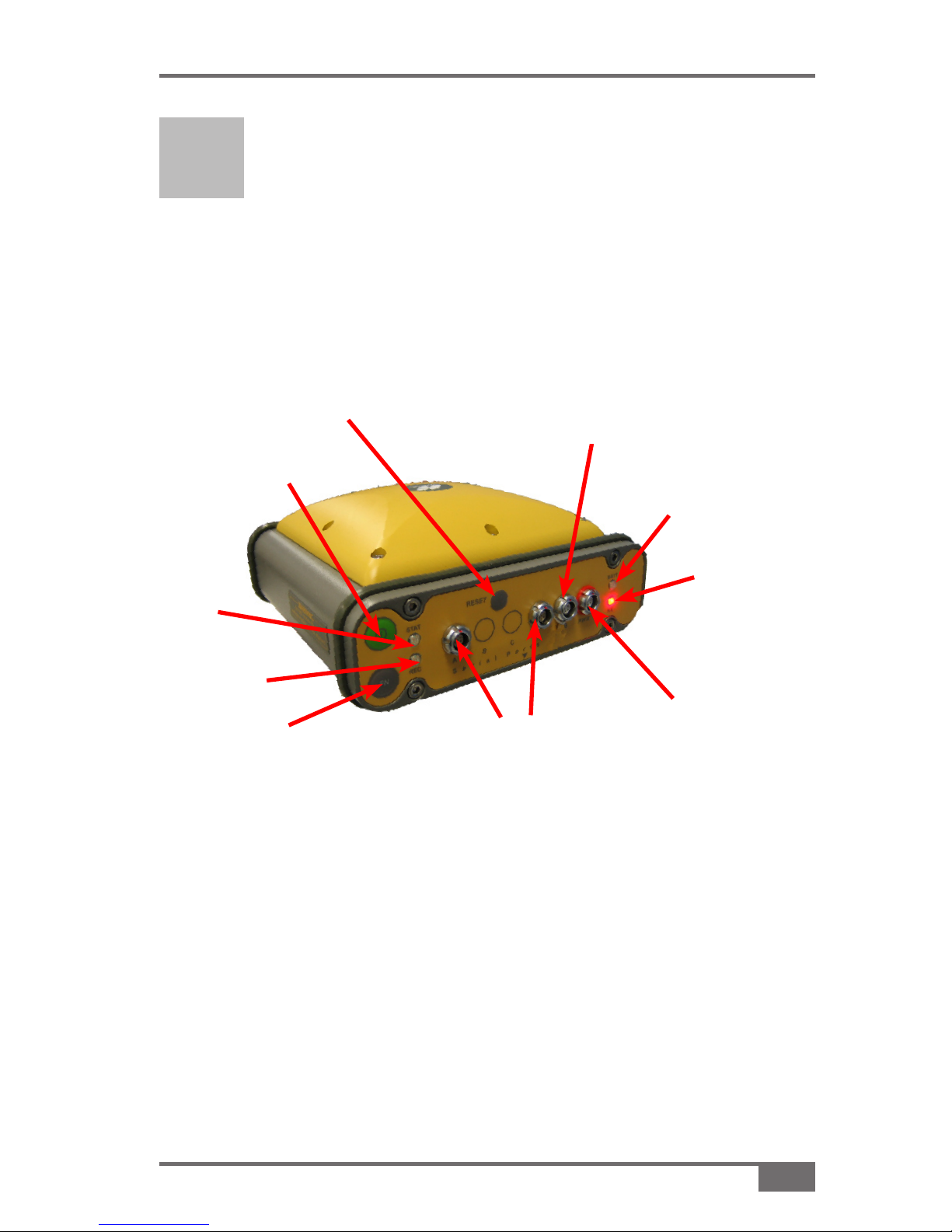
Layout of Hiper-AG Front Panel
Functions
• Power ON/OFF button—To power the Hiper-AG ON or OFF
hold down the Power button for 2 seconds
• GPS Status LED—This light indicates what satellites are
available to the GPS at the current time
Each green ash represents a visible GPS satellite 1.
Figure 4-1. Topcon Hiper-AG Layout
Reset
button
Function
(FN) button
Power ON/
OFF button
Battery
(BATT)
Modem/
Receive or
Transmit
(RX)
Status
(STAT)
Data Record
(REC)
External
Power
(PWR) Port
Serial Ports
USB Port (not used)
Page 16

4-2
www.topconpa.com
Topcon GPS Manual
Each red ash of the STAT light indicates that a 2.
Glonass (Russian) satellite is visible
Serial Ports—Transmits data to the console •
• Reset Button—Used for soft resets of the GMS. Do not use
the RESET button unless instructed to by a properly trained
technician
• Battery Status LED—This light ashes approximately every 4
seconds when the unit is switched ON. This light indicates the
battery condition
Green ashes indicate that the battery is in good 1.
condition
Orange ashes indicate that the battery is in a 2.
satisfactory condition
Red ashes indicate that the battery is in a poor 3.
condition
• RX—This light ashes every second when receiving GPS
corrections.
Page 17

5-1
A3524 Rev 1.1
Installing Topcon Hiper-AG RTK Mobile Base Station
Installing Topcon Hiper-
AG RTK Mobile Base
Station
The Hiper-AG RTK Base Station can be used in two different
congurations; either as a low-power mobile RTK Base Station or as a
high-power permanently xed RTK Base Station (see Chapter 6).
Required Components
Hiper-AG GPS receiver•
Power cable•
Comms cable•
UHF Portable antenna•
Mounting tripod•
Connecting the Power/ Communication cables
The two serial ports (Figure 5-1) can both be used to communicate with
the X20 console.
When the External Power Port (Figure 5-1) is connected to the 12V
battery (via the red-shrouded ODU cable) it provides the Hiper-AG’s
internal battery with power.
Page 18

5-2
www.topconpa.com
Topcon GPS Manual
Figure 5-1. Hiper-AG Ports
Communication
Cable in Serial Port
(connects to X20
console’s COM1 Port)
External
Power
(PWR) Port
Serial Ports
USB Port
Redshrouded
ODU cable
WARNING
Do not plug the External Power cable into the USB
port. This will destroy your Hiper-AG receiver.
WARNING
Use the attached port cover to seal the USB port. This will prevent any
accidental plugging of the external power into the USB port.
Communication with the X20 console is achieved by plugging the
Communication (Comms) cable (Figure 5-1) into either the A or D
Ports. The 9 pin (computer) plug on the other end of this cable plugs
into the COM1 Port on the back of the X20 console (Figure 5-2 on
page 5-2).
Page 19

5-3
A3524 Rev 1.1
Installing Topcon Hiper-AG RTK Mobile Base Station
Connect UHF Antenna
On the back of your Hiper-AG nd the port labeled UHF Antenna.
Connect the UHF antenna onto the Hiper-AG unit (Figure 5-4).
Figure 5-2. Connecting the Communication cable
Figure 5-3. UHF Port
Figure 5-4. Connect the UHF antenna
Communication
Cable:
Connects to
GPS Port
Communication Cable:
Connects to COM 1
Page 20

5-4
www.topconpa.com
Topcon GPS Manual
Positioning
The positioning of the Hiper-AG base must be in a clear area that does
not have trees, buildings or other obstructions nearby.
A 330’ (100m) radius is the minimum area required •
The higher the base is mounted, the better the radio coverage •
Placing the Hiper-AG in a hollow will reduce the radio range •
The radio transmission may be regarded as LINE OF SIGHT •
although sometimes a signal can still be received even when this
condition is not satised.
Assemble the Hiper-AG unit with the supplied bracket on the tripod
(Figure 5-3 on page 5-4).
Figure 5-3. Tripod
Deep-cycle
Battery
Hiper-AG unit
Page 21

5-5
A3524 Rev 1.1
Installing Topcon Hiper-AG RTK Mobile Base Station
Indicator LEDs
If none of the LEDs ash when the unit is powered ON the unit may be
in a Zero Power State (normally shipped in this state). To rectify this
press the RESET button.
If the LEDs still do not ash, the receiver’s internal battery may be at.
To rectify this plug the external power supply into the PWR socket
using the cable supplied with the red-shrouded ODU plug (see
“Connecting the Power/ Communication cables”, page 5-2).
There are 4 indicator LEDs on the face of the Hiper-AG.
Switching the Hiper-AG ON
Press and hold the green 1. Power button until the unit turns on.
When the unit turns on the LEDs should all ash, indicating power is
being supplied to the receiver.
If the unit does not turn on it is probably in Zero Power State
(see “Indicator LEDs”, page 5-5).
Green power
button
Figure 5-4. Press and hold the green power button to turn on unit
Page 22

5-6
www.topconpa.com
Topcon GPS Manual
Notes:
Page 23

6-1
A3524 Rev 1.1
Installing Topcon Hiper-AG RTK Fixed Base Station
Installing Topcon Hiper-
AG RTK Fixed Base
Station
The Hiper-AG RTK xed Base Station differs from the Hiper-AG
mobile Base Station in that it incorporates a high-gain antenna (Figure
6-1) and the radio power can be increased to its maximum output.
Required Components
Hiper-AG GPS receiver•
Power cable•
Comms cable•
UHF Portable antenna•
•
Figure 6-1. Fixed Base Station
UHF
Antenna
GPS
Antenna
Page 24

6-2
www.topconpa.com
Topcon GPS Manual
Conguration
This conguration is designed to be mounted semi-permanently in a
weather and vermin-proof structure with an external power supply
capable of supplying regulated voltage at maximum power drain.
Mounting Location
The Hiper-AG should be mounted where there is good air circulation
and no chance of moisture ingress.
Using the Hiper-AG as a Mobile Base Station
To use the Hiper-AG as a mobile Base Station remove the UHF Radio
Antenna, and the power source (see “Installing Topcon Hiper-AG RTK
Mobile Base Station”, Chapter 5).
Figure 6-2. Conguration and Mounting
Hiper-AG
unit
To UHF
Antenna
To GPS
Receiver
Page 25

6-3
A3524 Rev 1.1
Installing Topcon Hiper-AG RTK Fixed Base Station
Topcon Hiper-AG unit
Topcon UHF Radio
The high-gain Collinear (shing pole) Antenna (Figure 6-1 on page 6-1)
is connected to the BNC Connector of the Hiper-AG unit (Figure 6-3 on
page 6-2), via a thick black RG213 cable.
The RG213 cable has identical N-type connectors at each end.
There is a short adaptor cable supplied with a male N-type at one end
and a BNC connector at the other.
Screw the male N-Type connector of the adaptor cable to the 1.
female N-type connector of the RG213 cable
Connect the BNC connector on the other end of the short adaptor 2.
cable to the top of the Hiper-AG’s bayonet tting (Figure 6-3 on
page 6-2)
See “UHF Collinear Antenna Cable-RG213” on page 6-11 to 3.
complete the connection.
Figure 6-3. Hiper-AG unit
BNC
(Bayonet)
Connector
GPS Fitting
Page 26

6-4
www.topconpa.com
Topcon GPS Manual
PG-A1 RTK GPS Antenna with Ground Plane
The PG-A1 RTK GPS Antenna (Figure 6-4) is connected to the GPS tting of the Hiper-AG Base (Figure 6-3 on page 6-3) via a 5m cable with
threaded TNC connectors at each end.
Screw the male TNC connector of the cable to the female TNC 1.
connector of the PG-A1
Screw the TNC connector on the other end of the adaptor cable to 2.
the Hiper-AG’s GPS tting (Figure 6-3)
Figure 6-4. PG-A1 RTK GPS Antenna
TNC
Connector
Page 27

6-5
A3524 Rev 1.1
Installing Topcon Hiper-AG RTK Fixed Base Station
Power Connection
A power cable is supplied fo the Hiper-AG unit.
The power leads are tted with 3 amp automotive blade fuses.
The power cables are tted with ½” (12mm) insulated ring terminals for
connection to a (user-supplied) battery or other voltage-regulated power
source. The recommended battery size is 50 amp/hour and should be a
deep cycle type for mobile installations.
CAUTION
CAUTION
Do not change the 3 amp automotive blade fuses
to a higher rating as damage to the radio and/or
GPS could result.
Do not power the Hiper-AG unit until the external
antenna has been connected.
CAUTION
CAUTION
Page 28

6-6
www.topconpa.com
Topcon GPS Manual
UHF Collinear Antenna
The Hiper-AG xed Base Station will transmit to its maximum range if
it is connected to a series-fed UHF Collinear Antenna (see “UHF Collinear Antenna Cable-RG213”, page 6-11).
UHF Collinear Antennae are custom-tuned to the user’s frequency and
are constructed for null ll coverage and optimized range, for sites that
have an average height above ground level of less than 2000 metres.
The Collinear Antenna should be situated as high as possible, so that it
has unobstructed transmission coverage over buildings and trees. With
radio transmissions, height above local terrain is the most important
factor limiting range. Usually the antenna is xed to a customer
supplied pole/tower, either freestanding or on the top of farm
outbuildings to gain the required height and better line-of-sight.
Figure 6-5. UHF Collinear Antenna
Collinear
Antenna
Lightning
Arrestor
U Clamps
Page 29

6-7
A3524 Rev 1.1
Installing Topcon Hiper-AG RTK Fixed Base Station
Lightning Arrestor
The N-350NB Lightning Arrestor safeguards expensive electronic
equipment from damage caused by static electricity and lightning
induced surges, at a budget price.
The ultra-fast gas discharge tube safely shunts up to 5000 amps of
peak impulse current to an independent ground connection.
The N-350NB Lightning Arrestor is for use with externally
mounted antennas and comes with a female to male connector.
This device is inserted inline, to reduce the likelihood of a lightning
strike destroying your GPS equipment.
Figure 6-6. N-350NB Lightning Arrestor
Connects to
independent
ground
connection
Connects to
the bottom
of the UHF
Collinear
Antenna
Connects
to RG213
antenna cable
from PA-6
amplifier
WARNING
Failure to connect the Lightning Arrestor will result
in component failure and damage. This will not be
covered by manufacture warranty.
WARNING
CAUTION
Failure to fit the Lightning Arrestor could result in
electrical shock to humans and animals.
CAUTION
Page 30

6-8
www.topconpa.com
Topcon GPS Manual
Enhancing GPS and Radio Performance
Please note: The Antenna Mast is to be supplied by the end user, and is
not included in the Hiper-AG Base Station kit. The following diagram
and description is the ideal GPS and Radio Antenna support bracket.
Manufacture and erection of this mast to an
outbuilding/tower will enhance GPS and radio
performance.
TIP
TIP
Figure 6-7. Lightning Arrestor Support Bracket
1 Meter
1 Meter
2 Meters
1.5” Galv. Tubing
Stainless steel
hose/exhaust
clamps
Weld plate
(700mmx150mm)
with support brace
Apex of shed roof/
tower
Secure to
shed/ tower
Manufacture
pole from 1.5”
(38mm) galv.
tubing
Secure radio
antenna to
the bracket
using either
stainless steel
exhaust or
hose clamps
Weld a flat
base, 27”
(700mm) x
4” (100mm),
with a strut
support to
the pole. This
is the GPS
antenna plate.
Page 31

6-9
A3524 Rev 1.1
Installing Topcon Hiper-AG RTK Fixed Base Station
WARNING
Ensure the GPS Antenna Plate does not sit over
the structure’s roof. This may cause “multi-pathing
of the signal”, which will render the system
unusable.
WARNING
Figure 6-8. Setup of the GPS Antenna
Antenna mast (secured to
one end of the building)
UHF Antenna
RTK GPS Antenna
Figure 6-8 demonstrates the correct setup of the GPS Antenna.
This setup prevents “multi-pathing”. Figure 6-8 shows the:
• RTK GPS antenna mounted above and to the outside of the
building
• UHF Collinear Antenna mounted as high as possible, to gain
range advantage.
Page 32

6-10
www.topconpa.com
Topcon GPS Manual
Buildings reect the GPS signal to the tractor as shown in Figure 6-8
(page 6-9).
Mounting the GPS Antenna directly above the outbuilding roof will
result in the same confused input messages.
TIP
Make sure the GPS antenna is mounted above and
to the side of the outbuilding (Figure 6-9).
TIP
Figure 6-9. Fixed Base Station
Page 33

6-11
A3524 Rev 1.1
Installing Topcon Hiper-AG RTK Fixed Base Station
Self-Amalgamating Tape
Self-amalgamating tape is supplied. Using the tape to seal all external
antenna connections is recommended. The use of this tape will reduce
the chance of water ingress with consequent transmission failures.
UHF Collinear Antenna Cable – RG213
The UHF Collinear Antenna cable is a low-loss cable which should
be treated with care; sharp bends, nicks and cuts to the casing must be
avoided.
The supplied Antenna cable is 50’ (15m) in length. There is a 60’ (18m)
cable available at an extra cost, if required for taller towers etc.
The cable has an N-type connector at each end.
One N-type connector is connected to the Lightning Arrestor near the
UHF Collinear Antenna (Figure 6-6 on page 6-7) and the other end is
connected onto the Hiper-AG unit (Figure 6-3, page 6-3).
Any damage to this cable could cause severe reduction in the radio
transmission strength.
NOTICE
Do not join the N-type connectors together.
NOTICE
NOTICE
Once the UHF Collinear Antenna cable is securely
fitted to the Lightning Arrestor, firmly wrap the
connections with the self-amalgamating tape.
This will stop any moisture infiltrating the connections
and causing signal loss.
NOTICE
Page 34

6-12
A3524 Rev 1.1
Installing Topcon Hiper-AG RTK Fixed Base Station
Notes:
Page 35

7-1
A3524 Rev 1.1
Conguring Topcon Hiper-AG RTK Base Station (Mobile and Fixed)
Press 1. STOP>SETUP (Figure 7-1) when the Guidance program is
starting to access the Setup program
Select 2. GPS from the Setup Selection window
Conguring Topcon
Hiper-AG RTK Base
Station (Fixed and Mobile)
Figure 7-1. Accessing Setup Program
Page 36

7-2
www.topconpa.com
Topcon GPS Manual
Ensure that the Communication Cable is plugged into 3.
Communication Port A of the Hiper-AG (Figure 7-2)
Setup Program
The GPS Setup program has been developed with the end-user in
mind. It enables users and service personnel to setup and problem
solve Topcon’s and other brands of GPS used in Guidance and
Steering-assist applications.
Once the program is loaded into the X20 console, the screen
shown in Figure 7-3 (on page 7-3) will be displayed.
Figure 7-2. Hiper-AG Port A
Com Port A
Page 37

7-3
A3524 Rev 1.1
Conguring Topcon Hiper-AG RTK Base Station (Mobile and Fixed)
Select 4. Auto Connect (Figure 7-3) to connect the GPS
Select 5. Hiper GA as your receiver (Figure 7-4)
Once connected the status bar will turn green and the GPS type
will be displayed (Figure 7-4)
Select 6. Next (Figure 7-4) to continue
Figure 7-3. Auto Connect Button
Figure 7-4. Green Status Bar and Next Button
Status Bar
Page 38

7-4
www.topconpa.com
Topcon GPS Manual
The next screen to be displayed is the Status screen of the
Diagnostics tab.
Note that only one of the status boxes is green with numbers and
the rest are red without numbers inside. This is normal as a Base
Station does not need this data (a Rover GPS does however).
Figure 7-5. Diagnostics>Status Tab
Figure 7-6. Differential Source Tab
Status
Boxes
Page 39

7-5
A3524 Rev 1.1
Conguring Topcon Hiper-AG RTK Base Station (Mobile and Fixed)
Select the 7. Differential Source tab (Figure 9-6 on page 9-4)
Press 8. Set to Base Station (Figure 7-6) to set the Hiper-AG as a
Base Station
After a short pause the Base Station Setup window will
be displayed.
Select either 9. Single Base Station or Multi-Base Station,
depending on the number of base stations available (that are
broadcasting on the same frequency)
Press 10. OK (Figure 7-7)
Please note: Single Base Station setup is detailed from page 7-6, for
Multi-Base Setup see page 7-11.
Figure 7-7. Set to Base Station
Base
Station
Setup
window
Page 40

7-6
www.topconpa.com
Topcon GPS Manual
Single Base Station Setup
If Single Base Station was selected in step 6 on page 7-5 and the OK
button was pressed the program will display the window shown in
Figure 7-8.
After a short pause the program should display the Information
window shown in Figure 7-9.
Press 1. OK (Figure 7-9) to continue
Figure 7-8. Set to Base Station
Figure 7-9. Information Window
Page 41

7-7
A3524 Rev 1.1
Conguring Topcon Hiper-AG RTK Base Station (Mobile and Fixed)
Figure 7-10. Set Base Station Position Button
Select 2. Set Base Station Position (Figure 7-10)
The Set Base Station Position window will display (Figure 7-11)
Keep pressing 3. Refresh (Figure 7-11) until the altitude readings
Figure 7-11. Set Base Station Position Screen
Page 42

7-8
www.topconpa.com
Topcon GPS Manual
stabilizes to within 0.5m of each other.
To set the Base at the current position select4. Set position (Figure
7-11)
Other options include:
Auto Base— This will average positions for 3 minutes and •
set the averaged position into the receiver automatically
Get Position from List— Once a position is locked in using •
Set position, you can name the location and add it to a list
of previously saved positions by selecting Add Position To
List (See “Add Position to List”, page 7-9).
Saved positions can be recalled and reused to ensure the
base coordinates are exactly the same as previously used
at that location (see “Recalling Base Station Position from
List”, page 7-10).
Select 5. Set position (Figure 7-11) to store the current position in
the Hiper-AG’s memory
Please note: When setting the GPS as a Base Station, a position
must be logged into the receiver’s memory.
CAUTION
Do not move the GPS once it is fixed.
CAUTION
Page 43

7-9
A3524 Rev 1.1
Conguring Topcon Hiper-AG RTK Base Station (Mobile and Fixed)
Add Position to List
Select 1. Add Position to List (Figure 7-12) to
save the current position to the list
The onscreen keyboard (Figure 7-12) will appear.
Give the position a name by typing it into the keyboard (Figure 2.
7-12)
Press 3. OK when you have nished to save the name in the
position list (Figure 7-12).
Once the Base Station position has been saved to the list, it can be
Figure 7-12. Save Current Position to List
TIP
It is advisable to use this option to backup Base
Station location data.
TIP
Page 44

7-10
www.topconpa.com
Topcon GPS Manual
recalled and used instead of the current position in the GPS
receiver’s memory.
Select 1. Get Position From List (Figure 7-13)
Select ▼ next to 2. Name to view the dropdown list (Figure 7-14)
Pick the appropriate name (or number) 3.
In the example it is “Field 1”
Press 4. Select (Figure 7-14)
Press 5. Set Position (Figure 7-13)
Press 6. Close to exit the program
Figure 7-13. Accessing the List
Figure 7-14. Get saved position
Recalling Base Station Position from List
Page 45

7-11
A3524 Rev 1.1
Conguring Topcon Hiper-AG RTK Base Station (Mobile and Fixed)
Multi-Base Station Setup
If you selected Multi-Base Station in step 9 on page 7-5 follow these
instructions.
If there is a network of similar Base Stations in the vicinity that can be
used, then you should have selected the Multi-Base Station option in
step 6 on page 7-5.
If Multi-Base Station was selected in step 6 on page 7-5 and the OK
button was pressed the program will display the window shown in
Figure 7-15.
Select the total number of operating Base Stations 1.
Nominate which Base this is in the sequence of all the Bases 2.
(Used for time delay in the radio transmission)
Enter a Base ID (this will be a number from 1 to 31 that has not 3.
already been used by another Base in the network)
Press 4. OK (Figure 7-15)
The program will setup the Base Station parameters in the
receiver.
Figure 7-15. Multi-Base Station Setup
Total
Number
of Bases
Sequence
of this
Base
Base ID
(can be
used as a
password)
Page 46

7-12
www.topconpa.com
Topcon GPS Manual
The program will then display the message shown in Figure 7-16
once the Base Station is set up successfully.
Press 5. OK (Figure 7-16)
Follow the steps on pages 7-7 to 7-9 to set and save the Base 6.
Station position
To recall a position follow the steps on page 7-10.
Figure 7-16. Success
Page 47

Index
A524 Rev 1.1
Topcon GPS Manual
Index
A
Antenna Mast 6-7
AW400Tc UHF radio 5-4, 6-3
Assembly 5-4
power 6-1
B
Base Station Position 7-7
Recalling 7-10
Base Station Setup 7-5
Multi-Base Station 7-11
Single Base Station 7-6
Battery 5-4
BNC (Bayonet) Connector 6-3
C
Contact Information 1-4
D
Differential Source tab 7-5
G
GPS Performance 6-7
signal 6-9
I
internal battery 5-5
L
Index
LEDs 4-1, 4-2, 5-5
BATT 4-2
GPS 4-1
RX 4-2
Lightning Arrestor 6-6
CAUTION 6-6
M
Hiper-AG
Functions 4-1
Layout 4-1
Hiper-AG RTK Fixed Base Station
6-1
Conguration 6-2
Conguring 7-1
Mounting 6-2
Power Connection 6-4
Hiper-AG RTK Mobile Base Sta-
tion 5-1
Conguration 5-1
Conguring 7-1
Hiper-AG GPS Receiver
positioning 5-4
P
Power 4-1
Zero Power State 5-5
power cables 6-4
power supply 5-5
R
Page 48

www.topconpa.com
Topcon GPS Manual
Index
Radio Performance 6-7
Reset 4-2, 5-5
RG213 cable 6-3, 6-10
RTK GPS antenna 6-8
S
SAFETY 1-2
Self-Amalgamating Tape 6-10
Service Information 1-5
Setup program 7-1, 7-2
Status tab 7-4
T
Terms and Conditions 1-1
APPLICATION 1-1
COPYRIGHT 1-1
OTHER STATEMENTS 1-2
TRADEMARKS 1-2
WEBSITE 1-2
U
UHF Collinear Antenna 6-2, 6-3,
6-5
Assembly 5-4
Cable 6-10
positioning 6-5, 6-8
W
Warranty, Limited 1-2
Disclaimer 1-3
Electronic 1-2
Indemnity 1-3
Liability Limit 1-3
Mechanical Components 1-2
Repair 1-2
Return 1-2
WARNING 5-2, 6-6
 Loading...