

Page 1

X20 Sprayer Reference Manual
Part Number A2677
Rev. 1.5
© Copyright Topcon Precision Agriculture
March, 2008
All contents in this manual are copyrighted by Topcon. All rights
reserved. The information contained herein may not be used, accessed,
copied, stored, displayed, sold, modied, published or distributed, or
otherwise reproduced without express written consent from Topcon.
Page 2

Page 3

X20 Sprayer Reference Manual
Table of Contents
Preface............................................................................ 1-1
Terms and Conditions.................................................................. 1-1
Manual Conventions ................................................................... 1-6
Chapter 2
Introduction .................................................................... 2-1
Chapter 3
Using This Manual ......................................................... 3-1
First Time Users .................................................................................. 3-1
Operators Who Are Upgrading Their Software .................................. 3-1
Chapter 4
Before Installing or Servicing Your Spray ECU .......... 4-1
Testing Procedure ................................................................................ 4-2
Testing Procedure For Installations With No Existing Switchbox
(switches on existing controller) ................................................. 4-2
Testing Procedure For Installations With Existing Switchbox
(including Joystick Control) ........................................................ 4-3
Chapter 5
Installing the Spray ECU (all models) .......................... 5-1
Installing the Spray ECU 30S ............................................................. 5-2
Installing the Spray ECU 30S Topcon Precision Agriculture Sprayer
Kits ..................................................................................................... 5-4
Installing the Tractor Harness ..................................................... 5-5
Tractor Harness Extras ........................................................... 5-5
Two 37-Pin Connectors...................................................... 5-5
Connector 3 ........................................................................ 5-6
3-Pin Weather Pack Connector/Ground Speed .................. 5-6
A2677 Rev 1.5
i
Page 4

X20 Sprayer Reference Manual
Installing the Sprayer Harness ................................................... 5-8
Sprayer Harness Connectors .............................................. 5-8
Connecting to a Speed Sensor ..................................................5-11
Installing the Shaft/Speed Sensor Kit to an Un-Driven Wheel
for Ground Speed ..............................................................5-11
Installing the Shaft/Speed Sensor Kit to a Tailshaft ........ 5-15
Using an Existing Radar Speed Sensor for Ground
Speed ............................................................................... 5-16
Connecting to a Flow Meter .................................................... 5-17
Connecting to the Regulator Valve .......................................... 5-18
Pressure Sensor Installation and Connection ........................... 5-19
Installing the Valve Harness ..................................................... 5-20
Single Line Install ............................................................... 5-22
Dual Line Install ................................................................. 5-22
Connecting to the Dump Valve........................................... 5-23
Different Valve Types ............................................................... 5-25
Plumbing for Diaphragm Pumps for Topcon Precision Agriculture
Sprayer Kits .............................................................................. 5-26
Plumbing for Centrical Pumps for Topcon Precision Agriculture
Sprayer Kits .............................................................................. 5-27
Installing the Spray ECU 30S Kits to an Existing Topcon Precision
Agriculture Controller ....................................................................... 5-28
Before Removing the Existing Controller ................................. 5-28
Removing the Existing Controller ............................................. 5-28
Installing the Spray ECU 30S Kits ............................................ 5-28
Connecting the Spray ECU to the Battery ........................................ 5-31
Chapter 6
Getting Started ............................................................... 6-1
Warnings ............................................................................................. 6-1
Starting the X20 Console .................................................................... 6-2
Using Spray Controller Only ....................................................... 6-3
Using Spray Controller and Guidance ........................................ 6-3
About Spray Rate Controller Window ................................................ 6-4
ii
www.topconpa.com
Page 5

X20 Sprayer Reference Manual
Registering the Sprayer Software ................................................ 6-5
Overview of the Sprayer Working Screen Functions .......................... 6-6
Chapter 7
Conguration Setup ...................................................... 7-1
Audio Volume ..................................................................................... 7-2
Setting the Audio Volume............................................................ 7-2
Conguration ...................................................................................... 7-2
Change Current Conguration .................................................... 7-2
Load Conguration ..................................................................... 7-2
Selecting a Factory Conguration File .................................. 7-3
Setup ................................................................................................... 7-6
Quick Setup Guide ...................................................................... 7-6
Chapter 8
Conguration ................................................................. 8-1
GPS ..................................................................................................... 8-1
Automatic Section Control (ASC) .............................................. 8-1
Variable Rate Control (VRC)/Logging Mode ............................. 8-2
(VRC)/Logging Synchronization ................................................ 8-2
On Time ....................................................................................... 8-3
Off Time ...................................................................................... 8-4
Coverage Map Offset .................................................................. 8-4
Show Virtual Road If Moving ..................................................... 8-4
ASC Master Button ..................................................................... 8-4
VRC Master Button ..................................................................... 8-5
Electronic Control Unit (ECU) ........................................................... 8-6
COM Port .................................................................................... 8-6
Controller .................................................................................... 8-7
Using Injection ECU ................................................................... 8-7
Speed From ................................................................................. 8-8
Spray Interface ....................................................................... 8-8
Spray ECU ............................................................................. 8-9
ECU Conguration (Spray ECU Only) ..................................... 8-10
ECU Model .......................................................................... 8-10
Section Valve Mode ..............................................................8-11
Dump Valve Mode .................................................................... 8-12
A2677 Rev 1.5
iii
Page 6

X20 Sprayer Reference Manual
Tanks ................................................................................................. 8-13
Tanks ......................................................................................... 8-13
Tank 1 Mode ............................................................................. 8-14
Controller 1 ............................................................................... 8-14
Pressure (Pr) Sense ................................................................... 8-15
Regulator Valve Settings ........................................................... 8-16
Controller Mode ................................................................. 8-16
Reverse Valve Direction ..................................................... 8-20
Close Valve When Flow Off ............................................... 8-20
Sensitivity ........................................................................... 8-20
Proportional Valve Settings ....................................................... 8-21
Valve Options ..................................................................... 8-21
Min PWM ........................................................................... 8-22
Using High Minimum PWM Range Option ................ 8-22
Max PWM .......................................................................... 8-23
Controller Response ..................................................... 8-24
Sections ............................................................................................. 8-25
Lines .......................................................................................... 8-25
Sections ..................................................................................... 8-26
Setting the Number of Sections When Selecting Dual ....... 8-26
Setting the Number of Sections When Using a Primary
Section Valve to Switch Secondary Line On ...................... 8-27
Widths ....................................................................................... 8-27
Guidance Sections ..................................................................... 8-28
Valves ........................................................................................ 8-28
Nozzles ...................................................................................... 8-28
Total .................................................................................... 8-28
Min. Flow ........................................................................... 8-29
Switches ............................................................................................ 8-30
External Master Switch ............................................................. 8-30
External Auto Switch ................................................................ 8-31
External Section Switch ............................................................ 8-31
Switches (Spray ECU Only) ..................................................... 8-33
Boom Sensing ..................................................................... 8-33
Section Switches ................................................................. 8-34
Switch Mapping ................................................................. 8-34
Custom Section Mapping ................................................... 8-35
iv
www.topconpa.com
Page 7

X20 Sprayer Reference Manual
Use Presets .................................................................. 8-36
Undo ............................................................................ 8-36
OK ............................................................................... 8-36
Cancel .......................................................................... 8-36
Sensors .............................................................................................. 8-37
Pressure ..................................................................................... 8-37
Type ........................................................................................... 8-38
Input Gain .................................................................................. 8-38
Flow ........................................................................................... 8-38
Calibration Factor ............................................................... 8-39
Minimum Flow ................................................................... 8-40
Mico-Track Flow Sensor .................................................... 8-41
Sensors (Spray ECU Only) ....................................................... 8-42
Pressure .............................................................................. 8-42
Calibration Method ..................................................... 8-43
Sensor Specications .................................................. 8-44
Current .................................................................. 8-44
Voltage .................................................................. 8-45
Setup ................................................................................................. 8-46
Wheel Factor ............................................................................. 8-46
Manual Entry ...................................................................... 8-47
Calibrate ............................................................................. 8-47
Distance Check ................................................................... 8-48
Low Speed Options ................................................................... 8-49
Low Speed Shutoffs ........................................................... 8-49
Low Pressure Hold ............................................................. 8-50
Pressure Boost .................................................................... 8-51
Pump Options ............................................................................ 8-52
Enable Speed Smoothing .......................................................... 8-52
Setup (Spray ECU Only) ........................................................... 8-53
Enable Pump Control Button ............................................. 8-53
Holding Pressure ................................................................ 8-54
Units .................................................................................................. 8-55
Quick Set ................................................................................... 8-56
Lock NH3 Calibration Factor at Pulse per 1b ........................... 8-56
Alarms ............................................................................................... 8-57
A2677 Rev 1.5
v
Page 8

X20 Sprayer Reference Manual
Selecting the Alarm ................................................................... 8-58
Alarm Type ............................................................................... 8-58
Audio Alarm .............................................................................. 8-58
Select Tank ................................................................................ 8-59
Setting Alarms ........................................................................... 8-59
Tank Low Alarm % ................................................................... 8-60
Test Tank ................................................................................... 8-60
Defaults ..................................................................................... 8-60
Presets ............................................................................................... 8-62
Change Preset List ..................................................................... 8-62
Backup Preset List ..................................................................... 8-64
Simulation ......................................................................................... 8-65
Other ................................................................................................. 8-66
Language ................................................................................... 8-66
Effects ........................................................................................ 8-66
Chapter 9
Saving the Sprayer Conguration ............................... 9-1
Changing the Sprayer Settings of the Current Conguration ............. 9-3
New File Name ........................................................................... 9-5
Overwrite Existing File ............................................................... 9-5
Chapter 10
Setting Up the Sprayer ................................................ 10-1
Pressure Sensor ................................................................................. 10-1
Alarms ...................................................................................... 10-2
High Pressure....................................................................... 10-2
Low Pressure ....................................................................... 10-2
Calibrating the Pressure Sensor ................................................ 10-3
Correction Factor After a Pressure Calibration is
Unacceptable ....................................................................... 10-4
Manual Entry of Pressure Calibration Factors (Spray ECU
Only) ......................................................................................... 10-4
Flow .................................................................................................. 10-6
Speed ................................................................................................. 10-8
Area/Volume ................................................................................... 10-10
vi
www.topconpa.com
Page 9

X20 Sprayer Reference Manual
Tank Setup ...................................................................................... 10-13
Filling the Tank ....................................................................... 10-15
Flow Meter Setup ............................................................................ 10-17
Calibrating the Flow Meter ..................................................... 10-17
Flow Calibration for Balanced (Hardi) Valves ........................ 10-19
Enable Lockout ............................................................................... 10-21
Disable Lockout .............................................................................. 10-22
Sprayer Switchbox .......................................................................... 10-23
Chapter 11
Start Spraying ...............................................................11-1
Simulate Spraying ..............................................................................11-1
Start Spraying .....................................................................................11-3
Spraying in Manual Mode .........................................................11-4
Spraying in Auto Mode..............................................................11-4
While Spraying ..................................................................................11-5
Guidance and Spray Rate Control ......................................................11-6
Automatic Section Control (ASC) .............................................11-8
Chapter 12
Testing .......................................................................... 12-1
Regulator ........................................................................................... 12-1
Regulator Drive Test Procedure ............................................... 12-2
Switched Power ................................................................................ 12-3
Switched Power Test ................................................................ 12-3
Dump................................................................................................. 12-4
Dump Drive Test ...................................................................... 12-4
Topcon Sensors ................................................................................. 12-5
Sensor Input Test ...................................................................... 12-5
3 Wire Section Valves ....................................................................... 12-7
Section Valve Drive Test .......................................................... 12-7
Switch Master Switch ON ........................................................ 12-7
PWM Regulator Valve ...................................................................... 12-8
Prop Output Test ....................................................................... 12-8
A2677 Rev 1.5
vii
Page 10

X20 Sprayer Reference Manual
Chapter 13
Sprayer Components Spare Parts List ...................... 13-1
In Cab ................................................................................................ 13-1
Ground Speed/Shaft Sensor .............................................................. 13-2
Flow Sensors ..................................................................................... 13-2
Pressure ............................................................................................. 13-2
Dump Valve Adaptors (to suit Sprayer Harness) .............................. 13-3
Spares ................................................................................................ 13-3
Chapter 14
Specications .............................................................. 14-1
Console ............................................................................................. 14-1
Ground Speed, Fan Speed and Auxiliary Shaft Sensors ................... 14-2
Flow Sensors ..................................................................................... 14-2
Polmac (Broadacre) .......................................................................... 14-3
Orion (Broadacre) ............................................................................. 14-3
Pressure Transducer .......................................................................... 14-3
Chapter 15
Spray ECU 30S............................................................. 15-1
Console ............................................................................................. 15-1
Setup ................................................................................................. 15-2
Wiring Connection ............................................................................ 15-2
Connector 1 ............................................................................... 15-3
Connector 2 ............................................................................... 15-5
Connector 3 ............................................................................... 15-7
Connector 4 ............................................................................... 15-8
Chapter 16
Hardi 5500 Spray ECU ................................................. 16-1
Console ............................................................................................. 16-1
Connecting ........................................................................................ 16-2
Setup ................................................................................................. 16-2
Wiring Connection ............................................................................ 16-3
Connector 1 ............................................................................... 16-3
viii
www.topconpa.com
Page 11

X20 Sprayer Reference Manual
Connector 4 ............................................................................... 16-6
Connector 5 ............................................................................... 16-7
Chapter 17
Service Bulletins.......................................................... 17-1
Pressure Relief .................................................................................. 17-1
Fitting ........................................................................................ 17-1
Sprayer Software Settings ................................................................. 17-3
Setting the Pressure Relief ................................................................ 17-3
Chapter 18
Troubleshooting .......................................................... 18-1
Communication ................................................................................. 18-1
Speed ................................................................................................. 18-2
Boom Sections .................................................................................. 18-3
Rate and Pressure .............................................................................. 18-6
Control .............................................................................................. 18-9
Volumes ............................................................................................. 18-9
Nozzles ............................................................................................ 18-10
Alarms ............................................................................................. 18-10
Additional Data ................................................................................18-11
Appendix A
Options Window ................................................. Appendix
Index
A2677 Rev 1.5
ix
Page 12

X20 Sprayer Reference Manual
Notes:
x
www.topconpa.com
Page 13

X20 Sprayer Reference Manual
NOTICE
Preface
This manual has been developed to provide you with the information
necessary to operate and maintain this Topcon Precision Agriculture
(TPA) product. Proper service and use is important for the safe and
reliable operation of the product. The sections provided in this manual
include information necessary for the safe and correct operation, care,
and troubleshooting of this product. The benets this product provides
can be greatly inuenced by your knowledge of the products described
in this manual.
NOTICE
Please read these Terms and Conditions carefully.
Terms and Conditions
General
APPLICATION - You accept these Terms and Conditions by
purchasing the product from Topcon Precision Agriculture (TPA)
or from one of TPA’s product dealers.
COPYRIGHT - All information contained in this manual is the
intellectual property of, and copyrighted material of TPA. All
rights are reserved. You may not use, access, copy, store, display,
create derivative works of, sell, modify, publish, distribute, or allow any third parties access to, any graphics, content, information
or data in this manual without TPA’s express written consent and
may only use such information for the care and operation of your
product. The information and data in this manual are a valuable
asset of TPA and are developed by the expenditure of considerable work, time and money, and are the result or original
selection, coordination and arrangement by TPA.
A2677 Rev 1.5
1-1
Page 14

X20 Sprayer Reference Manual
TRADEMARKS – ZYNX, PRO STEER, EAGLE, KEE Technologies, Topcon, Topcon Positioning Systems and Topcon Precision Agriculture are trademarks or registered trademarks of the
Topcon Group of companies. Microsoft and Windows are trademarks or registered trademarks in the United States and/or other
countries of Microsoft Corporation. Product and company names
mentioned herein may be trademarks of their respective owners.
WEBSITE and OTHER STATEMENTS - No statement contained at the website of TPA or any other Topcon Group company
or in any other advertisements or TPA literature or made by an
employee or independent contractor of TPA modies these Terms
and Conditions (Including the software licence, warranty and
limitation of liability).
IMPORTANT: SAFETY - Improper use of the product can lead
to death or injury to persons, damage to property and/or malfunction of the product. The product should only be repaired by
authorized TPA service centres. You should closely review the
safety warnings and directions as to the proper use of the product
in this manual and at all times comply with the same.
Limited Warranty
ELECTRONIC and MECHANICAL COMPONENTS -TPA
warrants that the electronic components manufactured by TPA
shall be free of defects in materials and workmanship for a period
of one year from the original date of shipment to the dealer. TPA
warrants that all valves, hoses, cables and mechanical parts manufactured by TPA shall be free of defects in materials and
workmanship for a period of 12 months from the date of sale.
RETURN and REPAIR - During the respective warranty periods, any of the above items found defective may be shipped to
TPA for repair. TPA will promptly repair the defective item at no
charge, and ship it back to you. You must pay the shipping and
1-2
www.topconpa.com
Page 15

X20 Sprayer Reference Manual
handling charges in respect of the same. Calibration or compo-
nents, labour and travel expenses incurred for in-eld removal
and replacement of components are not covered in this warranty
policy. Damage to components due to negligence, abuse or im-
proper use, maintenance, modication or repair is NOT covered
under this warranty.
WARRANTY DISCLAIMER - Other than for the above warranties or warranties in an appendix or a warranty card accompanying the product, this manual and the product are provided ‘as
is’. There are no other warranties and to the extent allowed by
law TPA excludes all implied terms, conditions and warranties
in respect of the manual and the product (including any implied
warranty or merchantability or tness for any particular use or
purpose).
LIABILITY LIMIT and INDEMNITY - TPA and its dealers,
agents and representatives shall not be liable for technical or editorial errors or omissions contained herein or for special, indirect,
economic, incidental or consequential damages resulting from
the furnishing, performance or use of this material or the product
(including where TPA has been advised of the possibility of such
damage). Such disclaimed damages include but are not limited to
loss of time, loss or destruction of data, loss of prot, savings or
revenue or loss of or damage to the product. In addition, TPA is
not responsible or liable for damages or costs incurred in connection with obtaining substitute products or software, claims by
others, inconvenience, or any other costs.
In any event, TPA’s liability to you or any other person for any
claim, loss or damage (in contract, tort or on any other basis) will
be limited (in TPA’s option) to either (a) the replacement or repair
of the product, or (b) payment of the cost of replacing or repairing the product. You indemnify and hold TPA harmless against
any claim, action, damage, loss, liability or cost (including legal
fees) which TPA incurs arising from (a) your operation, use and/
or maintenance of the product other that in accordance with the
A2677 Rev 1.5
1-3
Page 16

X20 Sprayer Reference Manual
terms set out in this manual, or (b) your negligence or wrongful
act or omission in respect of the product.
Other
These Terms and Conditions may be amended, modied, superseded or cancelled, at any time by TPA. These Terms and Conditions will be governed by, and construed in accordance with:
- the laws of South Australia if the product is sold and supplied
to you in Australia (in which case the courts of South Australia or
the Federal Court of Australia (Adelaide Registry) have exclusive
jurisdiction in respect of any claim or dispute); or
- the laws of the State of California if the product is sold and supplied to you outside of Australia.
All information, illustrations, and applications contained herein
are based on the latest available information at the time of publication. TPA reserves the right to make product changes at any
time without notice.
If any part of these Terms and Conditions would be unenforceable, the provision must be read down to the extent necessary
to avoid that result, and if the provision cannot be read down to
that extent, it must be severed without affecting the validity and
enforceability of the remainder of these Terms and Conditions.
Comments, suggestions, and questions about TPA products are
welcomed. Contact your local TPA representative or a representative at our corporate facility.
Topcon Precision Agriculture
14 Park Way
Mawson Lakes, South Australia 5095.
Phone: +61 8 8203 3300
Fax: +61 8 8203 3399
A2677 Rev 1.5
1-4
Page 17

X20 Sprayer Reference Manual
Service Information
Service assistance can be provided by contacting your local TPA
Authorized Dealer or by calling the Topcon Precision Agriculture
Service Centre.
Phone: +61 8 8203 3300
Fax: +61 8 8203 3399
8.30am to 5pm (Adelaide Local Time), Monday through Friday.
A2677 Rev 1.5
1-5
Page 18
X20 Sprayer Reference Manual
TIP
NOTICE
CAUTION
WARNING
DANGER
Manual Conventions
This Manual uses the following conventions:
File>Exit ~ Click/tap/press the File menu, then click/tap/press Exit.
Enter ~ Click/tap/press the button or key labelled Enter.
Supplementary information that can help you congure,
maintain, or set up a system.
Supplementary information that can have an effect on
system operation, system performance, measurements
& personal safety.
Notication that an action has the potential to
adversely effect system operation, system
performance, data integrity, or personal health.
Notication that an action will result in systems
damage, loss of data, loss of warranty, or personal
injury.
UNDER NO CIRCUMSTANCES SHOULD THIS
ACTION BE PERFORMED.
1-6
www.topconpa.com
Page 19

X20 Sprayer Reference Manual
Introduction
The Spray Electronic Control Unit (ECU) is a new generation Spray
Controller, which is used in conjunction with the Topcon Precision
Agriculture X20 (or X15) console. The X20 console is the graphical
interface of the Spray ECU controller. The Spray ECU replaces the
Spray Rate Interface.
The Spray ECU can control up to 30 section valves (3 wire), and
allows Automatic Section Control (ASC) of the 30 section valves (the
X15 console can control up 15 sections under ASC). The Spray ECU
can control up to 2 liquid tanks directly. If the Spray ECU is used in
conjunction with a Multi-Drive Electronic Control (MDECU) unit, it
can control up to 3 liquid injection tanks.
The Spray ECU can handle Boom Sensing inputs, therefore it can be
connected to existing Remote switches. The Spray ECU also has a
new feature called Section Mapping, which allows one section switch
to control a number of section valves. Therefore the existing Topcon
Precision Agriculture Switchbox or remote switches (usually 6 or 8
switches) can control all 30 section valves, when they are controlled
manually. The X20 Sprayer software sets up the section mapping to
allow the six switches to control the 30 section valves. The ASC still
controls all 30 section valves individually.
The Spray ECU can control Regulator or Proportional type Control
Valves. The Spray ECU can control 3 Wire, 2 Wire (reverse polarity)
or Solenoid type Section Valves.
A2677 Rev 1.5
2-1
Page 20

X20 Sprayer Reference Manual
Notes:
2-2
www.topconpa.com
Page 21

X20 Sprayer Reference Manual
Using This Manual
This manual is written for:
First time users of this Spray ECU •
Operators who are upgrading their existing Sprayer software to •
a later version and their Spray Rate Interface or Spray ECU is
already installed.
First Time Users
First time users of Topcon Precision Agriculture’s Spray ECU must
read all chapters.
Operators Who Are Upgrading Their Software
Operators who are upgrading their existing Topcon Precision
Agriculture Sprayer software must read Chapter 4.
After reading Chapter 4, upgrading operators may then go to
Chapter 7, "Configuration Setup".
A2677 Rev 1.5
3-1
Page 22

X20 Sprayer Reference Manual
Notes:
3-2
www.topconpa.com
Page 23
X20 Sprayer Reference Manual
WARNING
TIP
WARNING
Before Installing or
Servicing Your Spray ECU
You must follow the procedures in this chapter to ensure your safety
while installing or servicing your Spray ECU.
WARNING
Damage will occur if any external power is
applied to the Section Drive Outputs on the
Spray ECU.
TIP
Follow the procedures carefully, to ensure that no
damage is done.
WARNING
Disconnect both the X20 console and Spray
ECU controller from the battery before charging,
jump starting or welding on the vehicle and/or
Sprayer.
A2677 Rev 1.5
4-1
Page 24

X20 Sprayer Reference Manual
WARNING
WARNING
Testing Procedure
WARNING
Before commencing testing procedure
disconnect the existing tractor harness from the
existing controller.
You must complete one of two testing procedures, before upgrading
your software.
Make sure you choose the testing procedure that is applicable to your
product.
Testing Procedure For Installations With No
Existing Switchbox (switches on existing
controller)
On existing tractor harness, turn the ignition on 1.
4-2
Check each Section Drive Output pin for voltage (refer to 2.
manufacturer manual of existing tractor harness for pin
details)
Locate where voltage is supplied, to determine if it can be 3.
removed without limiting existing functionality
WARNING
If it is not possible to remove this voltage, then
you must install a Section Drive Output Protection
Adaptor (A2812 for 37-pin on Connector 1 and
A2813 for 16-pin on Connector 3).
www.topconpa.com
Page 25

X20 Sprayer Reference Manual
WARNING
When no voltage is found, disconnect the vehicle’s battery 4.
before continuing with installation.
Testing Procedure for Installations With Existing
Switchbox (including Joystick Control):
Determine whether it is possible to disconnect the existing 1.
Switchbox without limiting existing functionality, eg: Boom,
Lift, Lower or Fold
WARNING
If it is not possible to remove the existing
Switchbox, without limiting functionality and
voltage is present, then you must install a Section
Drive Output Protection Adaptor (A2812 for 37-pin
on Connector 1 and A2813 for 16-pin on Connector
If it is possible to disconnect the existing Switchbox without 2.
limiting existing functionality disconnect the Switchbox
On existing tractor harness, turn the ignition on 3.
Check each Section Drive Output pin for voltage 4.
(refer to manufacturer manual of existing tractor
harness for pin details)
When no voltage is found, disconnect the vehicle’s 5.
battery before continuing with installation.
A2677 Rev 1.5
4-3
Page 26

X20 Sprayer Reference Manual
WARNING
WARNING
The vehicle battery must be disconnected before
proceeding with any installation or servicing of the
Spray ECU, Tractor, Sprayer or Valve Harnesses.
4-4
www.topconpa.com
Page 27
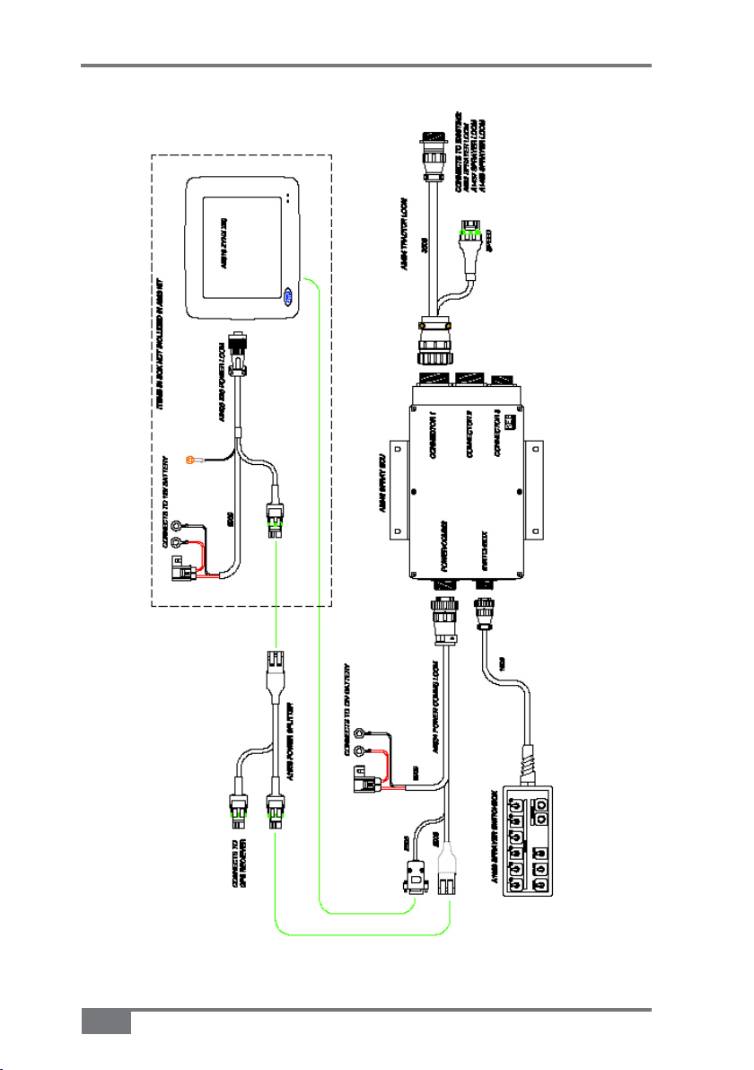
X20 Sprayer Reference Manual
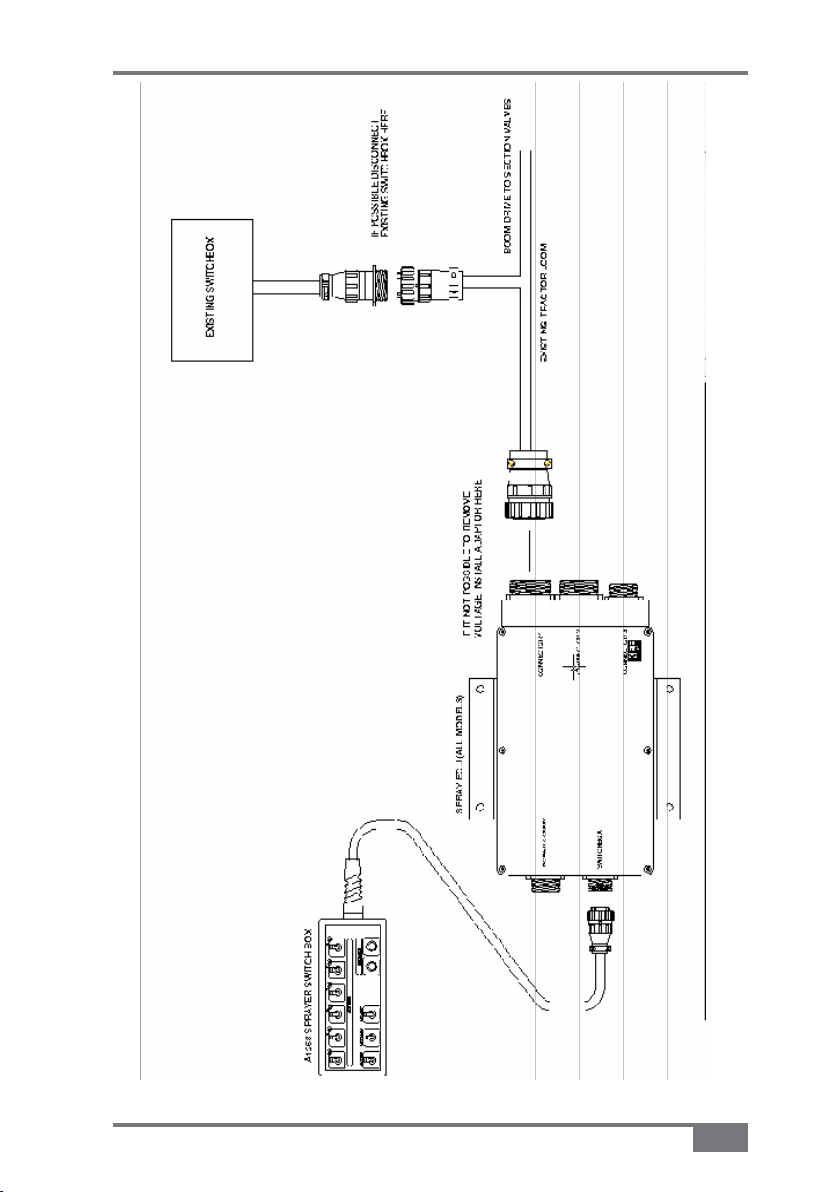
Figure 4-1. Connecting the Spray ECU to Existing Installations
A2677 Rev 1.5
4-5
Page 28

X20 Sprayer Reference Manual
Notes:
4-6
www.topconpa.com
Page 29
X20 Sprayer Reference Manual
WARNING
TIP
WARNING
Installing the Spray ECU
(all models)
This chapter is for first time operators of the Sprayer software. If you
are an operator who is installing upgrades to your existing software
(Spray Rate Interface or Spray ECU is already installed) please ensure
you have read Chapter 4, and then continue to Chapter 7.
WARNING
Damage will occur if any external power is
applied to the Section Drive Outputs on the
Sprayer ECU.
TIP
Follow the following procedures carefully, to ensure
that no damage is done.
WARNING
Disconnect both the X20 console and Spray ECU
controller, from the battery, before charging,
jump starting or welding on the vehicle and/or
Sprayer.
A2677 Rev 1.5
5-1
Page 30
X20 Sprayer Reference Manual
TIP
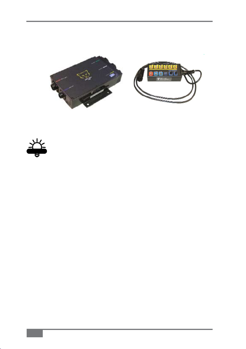
Installing the Spray ECU 30S
Figure 5-1. Spray ECU 30S Figure 5-2. Sprayer
TIP
When mounting the Spray ECU, it is important that
the Spray ECU itself, and its connectors cannot be
accidentally damaged by moving objects.
Switchbox
1. Mount the Spray ECU (Figure 5-1), in a suitable position inside
the cab.
The Spray ECU can be mounted in any orientation.
Figure 5-3 on page 5-7 shows the in cab assembly showing Spray
ECU, Switchbox, Power Comms and Tractor Harness.
5-2
www.topconpa.com
Page 31
X20 Sprayer Reference Manual
WARNING
NOTICE
TIP
Connect the 2. Power Comms harness to the Spray ECU and route
the red and black wires to a 12 Volt battery
WARNING
Do not connect the Power Comms harness to the
battery until the installation is complete.
NOTICE
Use the cable ties provided to secure the Power
Comms Harness away from hot and moving parts,
and to avoid chaffing and wear.
Plug the 3. Switched Power connector that is located on the Power
Comms Harness, into the Switched Power connector on the X20
Power Cable
TIP
If this connection is already being used, connect it
via the A1953 Power Splitter Harness.
This connection ensures that the Spray ECU is only powered up
when the X20 console is switched ON.
Connect the end of the Power Comms Harness, that has a 4. DB
9-Pin to the next available COM Port on the back of the X20
console
Connect the other end of the Power Comms Harness to the 5.
16-Pin connector marked POWER/COMMS on the Spray ECU
A2677 Rev 1.5
5-3
Page 32

X20 Sprayer Reference Manual
TIP
6. Connect the Sprayer Switchbox (Figure 5-2 on page
5-2), to the 9-Pin connector, marked SWITCHBOX on the
Spray ECU.
Mount the Sprayer Switchbox, using the double-sided tape
supplied (or other suitable means).
TIP
Mount the Sprayer Switchbox in a position which is
easily accessible while spraying.
Installing the Spray ECU 30S Topcon Precision
Agriculture Sprayer Kits
All Topcon Precision Agriculture Sprayer kits come with their
own installation guide, which is specific to each kit. Please use the
installation guide which came with your TPA Sprayer kit.
This section is a general guide for the installation of all Topcon
Precision Agriculture Spray ECU 30S Sprayer kits.
This section will cover:
Installing the • Tractor Harness
Installing the • Sprayer Harness
Installing the • Valve Harness.
5-4
www.topconpa.com
Page 33

X20 Sprayer Reference Manual
WARNING
NOTICE
Installing the Tractor Harness
Figure 5-3 on page 5-7 shows the in cab assembly showing Spray
ECU, Switchbox, Power Comms and Tractor Harness.
Connect the Tractor Harness to the 37-Pin connector marked 1.
CONNECTOR 1 on the Spray ECU
Run the Tractor Harness from the Spray ECU to the drawBar 2.
or the back of the vehicle.
NOTICE
Ensure that the Tractor Harness is tied away from
moving, hot and sharp objects.
WARNING
Do not cut or splice the Tractor Harness, all
excess cable should be strapped away to avoid
vibration and wear.
Tractor Harness Extras
Two 37-Pin Connectors
If your Tractor Harness has two 37-Pin connectors you
would have (in step 1) connected the male pin, marked
CONNECTOR 1 to the plug marked CONNECTOR 1 on the
Spray ECU.
You will also have to plug the other 37-Pin connector
(female pins), marked CONNECTOR 2 to the plug marked
CONNECTOR 2 on the Spray ECU.
A2677 Rev 1.5
5-5
Page 34

X20 Sprayer Reference Manual
NOTICE
Please note: As a general rule the CONNECTOR 2 plug is
only required if the Sprayer:
Has more than 10 Boom Sections •
Has more than 2 tanks •
Is connecting to external switches which control the •
Boom Sections (boom sensing), eg: Boom Section
switches on a T Bar or Joy Stick or other third party
section switches.
Connector 3
Normally CONNECTOR 3 (16 pin) is only required if the
Sprayer requires extra pressure inputs, tank level sensors and
extra encoder inputs.
3-Pin Weather Pack Connector/Ground Speed
5-6
The Tractor Harness has a 3-Pin Weather Pack connector
labelled ‘Ground Speed’.
Either an A328 Shaft/Speed Sensor Kit or A449 Radar Sensor
Interface Harness (not included in this kit) can be connected
to this connector.
Typically, the Radar Sensor Interface Harness would be
connected to the Tractor Harness Ground Speed Connector.
NOTICE
Only one speed connector can be used at any one
time.
See "Connecting to a Speed Sensor", page 5-11 for installing
the Shaft/Speed Sensor Kit or Radar Interface Kit.
www.topconpa.com
Page 35

X20 Sprayer Reference Manual
A2677 Rev 1.5
Figure 5-3. General In Cab Assembly
5-7
Page 36

X20 Sprayer Reference Manual
WARNING
Installing the Sprayer Harness
Figure 5-5 on page 5-10 shows the Sprayer Harness and Valve
Harness Assembly.
Connect the connector on the Sprayer Harness to the Tractor 1.
Harness, at the back of the tractor or vehicle
Continue to run the Sprayer Harness across the Sprayer’s 2.
chassis, to the valve set
WARNING
Do not cut or splice the Sprayer Harness; all
excess cable should be strapped away to avoid
vibration and wear.
Sprayer Harness Connectors
The typical Sprayer Harness has 5 connectors (Figure 5-5 on
page 5-10), which are labelled:
• Ground Speed—connects to the Shaft/Speed Sensor Kit
(supplied in kit)
• Flow Meter 1—connects to a Flow Meter (not supplied in
kit)
• Pressure Sensor 1—connects to the Pressure Sensor
(supplied in kit)
• Reg Valve 1—connects to a Regulator Valve (not supplied
in kit)
• Valve Harness—connects to the Valve Harness (supplied in
kit).
5-8
www.topconpa.com
Page 37

X20 Sprayer Reference Manual
TIP
Please note: The Sprayer Harness may have other connectors,
refer to the Sprayer Installation kit that came with your Sprayer
kit for more information.
The Dump Valve connector may be located on the Sprayer
Harness. If the Valve Harness has an Arag Interface box
incorporated into the Valve Harness, then the Dump Valve
connector will be located on the Valve Harness.
Figure 5-4. 3-Pin Weather Pack Sensor
TIP
For testing purposes on all 3-Pin sensor connectors
(Shaft/Speed Sensor and Flow Meter) the voltage on
each pin should be:
See Figure 5-4.
A2677 Rev 1.5
Pin A: +% VDC Signal •
Pin B: Ground •
Pin C: +12VDC Sensor Power •
5-9
Page 38

X20 Sprayer Reference Manual
Figure 5-5. General Sprayer and Valve Harness assembly
5-10
www.topconpa.com
Page 39

X20 Sprayer Reference Manual
NOTICE
NOTICE
Connecting to a Speed Sensor
This installation is used if connecting an A238 Shaft/Speed Sensor
kit (for ground speed) or A449 Radar Sensor Interface Harness
(not supplied in kit) to the Ground Speed Connector on either the
Tractor Harness or Sprayer Harness.
NOTICE
Connect to only one of the Ground Speed
connectors.
Select one of the following:
Installing the Shaft/Speed Sensor kit to an un-driven wheel on •
either the Tractor Harness or Sprayer Harness
Installing the Shaft/Speed Sensor kit to the Tailshaft of a •
vehicle on either the Tractor Harness or the Sprayer Harness
Use an existing Radar Speed sensor for Ground Speed•
Installing the Shaft/Speed Sensor Kit to an
Un-Driven Wheel for Ground Speed
NOTICE
Use of a driven wheel for ground speed may be
subject to “wheel slip” and may not always reflect
true ground speed.
The Shaft/Speed Sensor and Wheel Stud Magnets can be fitted to
any un-driven ground wheel, eg: the front wheel of the tractor or
wheel on a trailing Sprayer.
The magnet activates the sensor as the wheel magnets sweep past
(Figure 5-6 on page 5-12).
A2677 Rev 1.5
5-11
Page 40

X20 Sprayer Reference Manual
TIP
NOTICE
NOTICE
NOTICE
A wheel Calibration Factor of no greater than 0.6m
(24 inches) is required. See Section
1. Glue the magnets to the wheel studs (Figure 5-6), with the
side marked with a plus (+) facing the Shaft/Speed Sensor.
TIP
Use any silicone or epoxy type adhesive to glue the
magnets to the wheel studs. Make sure you leave
adequate time for the glue to set.
NOTICE
Space the magnets equally around the wheel, on
all the available wheel studs (Figure 5-6), to ensure
accurate speed updates.
Figure 5-6. Shaft/Speed Sensor on an Un-Driven Wheel Installation
5-12
www.topconpa.com
Page 41

X20 Sprayer Reference Manual
NOTICE
NOTICE
Mount the Shaft/Speed Sensor to an existing structure on the 2.
wheel axle, ideally in a protected position to face the magnet.
NOTICE
The distance between the Shaft/Speed Sensor to
Wheel Stud Magnet needs to be 2 to 3 mm (1/16 to
1/8 inch). The Shaft/Speed Sensor must be mounted
so that the Wheel Stud Magnets pass the sensor
evenly and squarely.
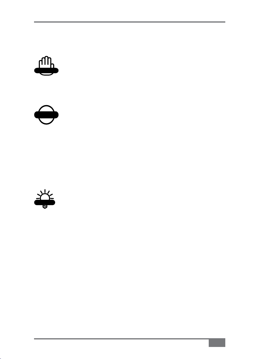
To mount the Shaft/Speed sensor you can either:
Use the Mounting Bracket Assemblies (slotted brackets •
and angle brackets with hose clamps) provided (Figure
5-7 on page 5-14)
Fabricate your own mounting bracket to suit the •
Sprayer chassis.
NOTICE
There must be no movement of the sensor relative to
the magnet.
A2677 Rev 1.5
5-13
Page 42
X20 Sprayer Reference Manual
NOTICE
NOTICE
Figure 5-7. Shaft/Speed Sensor with Mounting Bracket
If necessary, protect the Shaft/Speed Sensor and wiring from
damage by welding or bolting a suitable plate over them.
NOTICE
Damage to the front face of the Shaft/Speed Sensor
will stop the speed readout and prevent the controller
from working.
NOTICE
If the Shaft/Speed sensor is mounted on a steered
wheel, then make sure the sensor moves with the
steering mechanism, to maintain constant clearance
between the magnets and the sensor when the wheel
is turning from lock to lock.
If required, use the 3-Pin Weather Pack Extension provided, by
connecting the Shaft/Speed Sensor to either the Ground Speed
connector on the Tractor Harness or Sprayer Harness.
5-14
www.topconpa.com
Page 43
X20 Sprayer Reference Manual
NOTICE
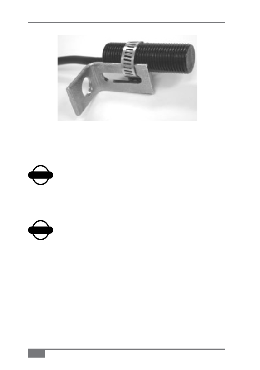
Installing the Shaft/Speed Sensor Kit to a
Tailshaft
On a tray mounted Sprayer the Shaft/Speed Sensor kit can be
used to read from the vehicle Tailshaft (Figure 5-8).
Securely 1. mount the Magnet Block on the flange, between the
Transmission Housing and Tailshaft, using the Hoseclamp or
other suitable means (Figure 5-8)
NOTICE
Do not attach the Magnet Block (Figure 5-8) directly to the
Tailshaft as its position changes, throughout its rotation.
Please note: The wheel stud magnets are not used in this
case.
Figure 5-8. Shaft/Speed Sensor installation to a Tailshaft
Securely mount the Shaft/Speed Sensor so it squarely faces 2.
the Magnet Block with a clearance of 2 to 3mm (1/16 to 1/8
inch), using an existing bolt on the transmission housing and
the supplied Mounting Brackets or other suitable means.
A2677 Rev 1.5
5-15
Page 44

X20 Sprayer Reference Manual
CAUTION
Ensure that the Shaft/Speed Sensor is firmly attached and
protected so that it cannot be damaged by wire or stones. If
necessary cover the Shaft/Speed Sensor with a plate.
If required, use the 3-Pin Weather Pack Extension provided,
by connecting the Shaft/Speed Sensor to either the Ground
Speed connector on the Tractor Harness or Sprayer Harness.
Using an Existing Radar Speed Sensor for
Ground Speed
An optional Radar Sensor Interface Harness (A449−not provided
in kit but can be ordered separately) allows direct connection to
any existing Radar Speed Sensor on the tractor.
Connect the 1. Radar Sensor Interface Harness to the Ground
Speed connector on the Tractor Harness or Sprayer
Harness
Connect the other end of the wire to the signal wire from 2.
the Radar Sensor (not provided in kit) to enable the Spray
ECU to read the speed.
CAUTION
Check the Radar Sensor Manufacturer’s manual
before attempting connection.
If required, use the Extension Harness provided, by connecting the
Radar Sensor to either the Ground Speed connector on the Tractor
Harness or Sprayer Harness.
5-16
www.topconpa.com
Page 45

X20 Sprayer Reference Manual
CAUTION
NOTICE
NOTICE
Connecting to a Flow Meter
The Flow Meter (not supplied in kit) is installed between the
Regulator Valve and the Section Valves. The Flow Meter will
be installed so that it measures only the quantity of liquid being
delivered to the spray line.
NOTICE
There must be no return line to tank or pump after the
Flow Meter.
Connect the Flow Meter 3-Pin Connector to the 3-Pin 1.
connector marked Flow Meter 1 on the Sprayer Harness
(Figure 5-5 on page 5-10)
NOTICE
The Flow Meter may require a connector change to
attach to the 3-Pin connector marked Flow Meter 1 on the
Sprayer Harness. Refer to the Flow Meter manufacturer’s
specifications for correct pin allocation.
CAUTION
Care should be taken when replacing these
connectors, not to damage the Sprayer Harness or
Flow Meter and connectors should be fully circuit
tested prior to installation.
A2677 Rev 1.5
5-17
Page 46

X20 Sprayer Reference Manual
NOTICE
NOTICE
Most Flow Meters have a label on the meter body that shows the
Flow Meter Calibration Factor in pulses/volume. Eg: ‘645 ppl
(pulses per liter)’ or ‘2441 ppg (pulses per gallon)’. This means
the Flow Meter sends 645 pulses to the Spray ECU for every liter
(or 2441 pulses for every gallon) of liquid that passes through
the Flow Meter. This value is the Calibration Factor and will
be required to be entered into the Sprayer software setup (see
“Calibration Factor”, page 8-39).
NOTICE
If connecting to a Raven Flow Meter. The value marked
on the label represents pulses/10 units of liquid. Divide
this number by 10 for the correct value to enter as the
Calibration Factor into the Sprayer software setup.
Connecting to the Regulator Valve
The Regulator Valve (not supplied) is a motorized flow control
valve used to maintain the product flow to the section valves. It
will be situated between the pump and the Flow Meter.
5-18
NOTICE
All bypass or agitation return lines that return to the tank,
must be taken before the Regulating Valve, so there is
no return path after the Regulating Valve and the Flow
Sensor.
Connect the Regulator Valve’s 2-Pin connector to the 2-Pin 1.
connector marked REG Valve 1 on the Sprayer Harness
(Figure 5-5 on page 5-10), using the Regulator Valve Adaptor
Harness (A802) (Figure 5-5 on page 5-10)
www.topconpa.com
Page 47

X20 Sprayer Reference Manual
NOTICE
NOTICE
CAUTION
NOTICE
The Regulator Valve may require a connector change
to attach to the 2-Pin connector marked REG Valve 1
on the Sprayer Harness. Refer to the Regulator Valve
manufacturer’s specifications for correct pin allocation.
CAUTION
Care should be taken, when replacing these
connectors, not to damage the Sprayer Harness or
Regulator Valve and connectors should be fully circuit
tested prior to installation.
When you test the Sprayer with water you may find that the
Regulator Valve works in the opposite direction to what you
require. For example: The pressure increases when it should
decrease. You can set the Reverse Valve Direction in the Sprayer
software setup to remedy this, see “Reverse Valve Direction”, page
8-20.
Pressure Sensor Installation and Connection
1. Mount the Pressure Sensor (A092) (Figure 5-5 on page 5-10)
either upright or horizontally and support the Brass Gauge
saver
The supplied Pressure Sensor is a 5 Bar (72 psi) Pressure
Sensor.
NOTICE
To properly measure Spray Line operating pressure the
Pressure Sensor must be positioned between the Flow
Meter and the Section Valves (Figure 5-5 on page 5-10).
A2677 Rev 1.5
5-19
Page 48

X20 Sprayer Reference Manual
NOTICE
Connect the 2. Pressure Adaptor Harness (H1125) to the
connector labeled Pressure Sensor 1 on the Sprayer Harness
(Figure 5-5 on page 5-10)
Undo the two nuts ontop of the Pressure Sensor 3.
Place the two ring terminals, on the Pressure Adaptor 4.
Harness, onto the terminals on the Pressure Sensor
It does not matter which way around the terminals are
attached to the Pressure Sensor.
Replace the two nuts and tighten the nuts securely.5.
Installing the Valve Harness
Figure 5-5 on page 5-10 shows the Sprayer Harness and Valve
Harness Assembly.
The Valve Harness continues from the connector on the Sprayer
Harness and connects to the Section and Dump Valves on the
Sprayer.
The Valve Harness normally contains connectors for the section
valves, they are either: 3 Wire Section Valves, 2 Wire Section
Valves or Solenoid Valves. See “Different Valve Types”, page
5-25 for an explanation of the different types of Section Valves.
NOTICE
If the Valve Harness has an Arag Interface Box
incorporated into the Harness then the Dump Valve plug
will be on the Valve Harness.
5-20
www.topconpa.com
Page 49

X20 Sprayer Reference Manual
WARNING
NOTICE
The typical Valve Harness has the following connectors, which
are labelled as follows:
• Dump 1—connects to the Dump Valve
• Section X—connects to the Section Valves. ‘X’
represents the section number
• Sprayer Harness—connects to the Sprayer Harness.
There are different Valve Harness’, depending on which type of
Section Valves are fitted on the Sprayer.
WARNING
If the Valve harnesses need to be re-terminated,
because the connectors are different to the section
valves being connected to, then you should
ensure the Sprayer Harness is disconnected from
the Tractor Harness. Otherwise damage to the
Spray ECU will occur if the wires are shorted out
during the installation.
Connect the Valve Harness to the Sprayer Harness. 1.
NOTICE
Use the cable ties provided to secure the
Power/Comms Harness away from hot and moving
parts, and to avoid chaffing and wear.
A2677 Rev 1.5
5-21
Page 50

X20 Sprayer Reference Manual
TIP
TIP
Single Line Install
Connect the connectors marked Section X to the correct 1.
section valves
TIP
If there are too many connectors for the section
valves use the connectors with the lowest
numbers first.
• Section 1— connects to the section valve on the far left
• Section 2—connects to the next section valve, and so
forth, until all the section valves are connected to the
Valve Harness
The section valve with the highest number will operate •
the Boom Section on the far right.
5-22
2. Cable-tie the spare connectors to the Valve Harness.
Dual Line Install
Connect the connectors that operate the primary Spray 1.
Line (Spray A)
TIP
Use the lowest numbers first.
Section 1 will operate the section on the far left of the
spray line (when facing forward) and the highest number
section valve on Line A will operate the far right Boom
Section.
www.topconpa.com
Page 51

X20 Sprayer Reference Manual
WARNING
NOTICE
TIP
WARNING
If the Valve Harness needs the connectors
replaced to suit the valve connectors, then
you should ensure that the Sprayer Harness is
disconnected from the Tractor Harness. Otherwise
damage to the Spray ECU will occur, if the wires
are shorted out during this procedure.
Connecting to the Dump Valve
The Dump Valve (not supplied in kit) is activated when all
sections are switched OFF or when the Master Switch is switched
OFF, this directs all the flow back to the tank.
NOTICE
The Dump Valve must be located between the pump
and Flow Meter.
TIP
If you notice that the Dump Valve is going in the
wrong direction, you have to swap the wires in the
Arag connector.
A2677 Rev 1.5
Connect the ARAG connector labeled 1. Dump 1 to the Dump
Valve
If the Dump Valve connector is on the Sprayer Harness,
then an adaptor will be required to connect the 4-Pin
Weather Pack to the Dump Valve. You must connect the
correct adaptor to the Dump Valve. See Table 5-1 on page
5-24 to determine which adaptor you should use.
5-23
Page 52

X20 Sprayer Reference Manual
Choosing the Correct Adaptor for the Dump Valve
Part No. Usage
Use if connecting to a 2-wire dump valve and 12V
A2266
is applied to the dump valve when the Master switch
is OFF
Use if connecting to a Solenoid Valve, with 6mm
A2267
spade terminals and 12V is applied to the dump
valve when the Master switch is OFF
A2268 Use if connecting to a 3-Wire Dump Valve and 12V
is applied to the Dump Valve when the Master is
OFF
Use when connecting to a 3-Wire Dump Valve and
A2269
12V is applied to the Dump Valve when the Master
is ON
Figure 5-1. How to Choose the Correct Adaptor for the
Dump Valve
When all the Arag connectors are in place, tighten the 2.
screw at the top of the Arag connector, using a screwdriver,
to secure the connector to the Section and Dump Valves
5-24
Tidy any excess harness, using cable ties3.
To complete the installation go to page 5-31, to connect the
Spray ECU Power/Comms Harness to the battery.
www.topconpa.com
Page 53

X20 Sprayer Reference Manual
Different Valve Types
There are three different valve types, which are:
• 2-Wire Valve—this refers to an electric section, dump or
Regulator Valve
The valve is driven by an electric motor that is able to rotate
in both directions. Two wires are connected to this type of
valve from the controller. To rotate the motor 12V is applied
to one of the wires whilst GND is applied to the other. When
opposite voltage is applied to the two wires the motor will
rotate in the opposite direction.
Common terms for this system are Reverse Polarity or
Bi-Directional.
• 3-Wire Valve—this refers to an electric section, dump or
Regulator Valve
The valve is driven by an electric motor that is able to
rotate in both directions. Unlike the 2-wire valve, the 3-wire
valve has in built changeover relays that change the motor
direction, depending on whether 12V or 0V is applied to the
signal wire.
Contsant 12V and GND are required in addition to the signal
wire.
• Solenoid Valve—this refers to electromagnetic coil type
valves.
Solenoid Valves usually consist of a coil, that when exposed
to voltage produces a magnetic field. The magnetic field
draws a needle against a spring away from its seat, to allow
liquid to flow.
A2677 Rev 1.5
5-25
Page 54

X20 Sprayer Reference Manual
Plumbing for Diaphragm Pumps for Topcon
Precision Agriculture Sprayer Kits
Figure 5-9. Plumbing for Diaphragm Pumps for TPA Sprayer Kits
5-26
www.topconpa.com
Page 55

X20 Sprayer Reference Manual
Plumbing for Centrrfical Pumps for Topcon
Precision Agriculture Sprayer Kits
Figure 5-10. Plumbing for Centrical Pumps for TPA Sprayer Kits
A2677 Rev 1.5
5-27
Page 56

X20 Sprayer Reference Manual
Installing the Spray ECU 30S Kits to an Existing
Topcon Precision Agriculture Controller
This section is for users who are replacing an existing Topcon
Precision Agriculture (I.E. KEE) MK3, MK5 Sprayer console or Spray
Rate Interface.
Before Removing the Existing Controller
Ensure that the system is functioning correctly 1.
Run the Sprayer and record the minimum and maximum 2.
pressure and flow rates attainable
Record all of the calibration factors 3.
Record all of the section width values.4.
Removing the Existing Controller
Remove the existing TPA Spray Rate Controller console or 1.
TPA Spray Rate Interface
Remove the existing Tractor Harness. 2.
Installing the Spray ECU 30S Kits
Connect the Tractor Harness to 1. Connector 1 on the Spray
ECU (Figure 5-11 on page 5-30)
The Tractor Adaptor Harness connects to the Spray ECU
and runs the Harness as far as the drawBar of the tractor or
vehicle, where a breakaway is attached so the vehicle can be
easily detached from the trailing Sprayer.
5-28
www.topconpa.com
Page 57

X20 Sprayer Reference Manual
NOTICE
WARNING
WARNING
TIP
NOTICE
Care should be taken when running the Tractor
Harness from the Spray ECU.
Lead the Harness from the Spray ECU to the back of the 2.
vehicle
TIP
Tie cable back, where possible.
WARNING
Do not cut or splice the Sprayer Harness, all
excess cable should be strapped away to avoid
vibration and wear.
Securely mount the 3. Breakaway connector above any hydraulic
outlets, to reduce the risk of oil ingress to the connectors
WARNING
Do not expose the connectors to high pressure
water or oil.
Connect the Tractor Adaptor Harness to the existing Sprayer 4.
Harness.
Refer to the console manual for installing the console to the
vehicle.
To complete the installation go to page 5-31, to connect the
Spray ECU Power/Comms Harness to the battery.
A2677 Rev 1.5
5-29
Page 58
X20 Sprayer Reference Manual
Figure 5-11. General Layout of Spray ECU Connecting to Existing
Topcon Precision Agriculture Sprayer Harness
5-30
www.topconpa.com
Page 59
X20 Sprayer Reference Manual
WARNING
WARNING
CAUTION
Connecting the Spray ECU to the Battery
WARNING
Do not attach the wires to the battery terminals
until the installation of the Tractor Harness,
Sprayer Harness and Valve Harness is completed.
WARNING
If your tractor uses 24 Volt batteries, you must use
a 12 Volt/15 Amp (minimum) inverter.
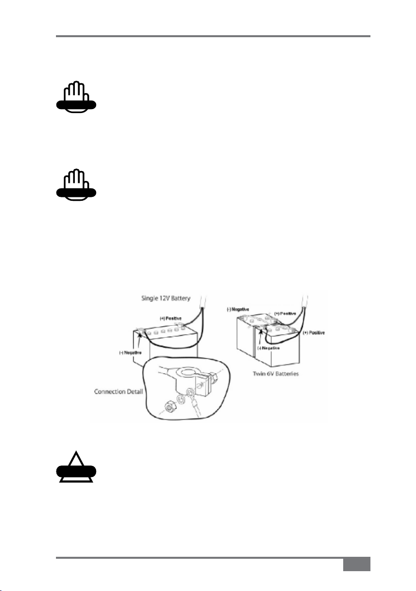
Connect the Power/Comms Harness directly to 12 VDC battery 1.
terminals (Figure 5-12)
Figure 5-12. Battery Conguration
CAUTION
Do not connect the Power/Comms Harness to
an alternator or starter motor as this may cause
interference or power fluctuations or surges and
may damage your system.
A2677 Rev 1.5
5-31
Page 60
X20 Sprayer Reference Manual
WARNING
WARNING
CAUTION
Attach the red wire to the positive (+) battery terminal (Figure 2.
5-12)
WARNING
Do not connect the black wire to the vehicle
chassis unless an Isolation Switch is fitted to the
negative side of the battery.
Attach the black wire to the negative (-) battery terminal (Figure 3.
5-12)
WARNING
Except for other Topcon Precision Agriculture
products do not power other equipment from the
power cable.
5-32
CAUTION
Connection to the battery terminals must be kept
clean and tight at all times.
www.topconpa.com
Page 61
X20 Sprayer Reference Manual
Getting Started
Warnings
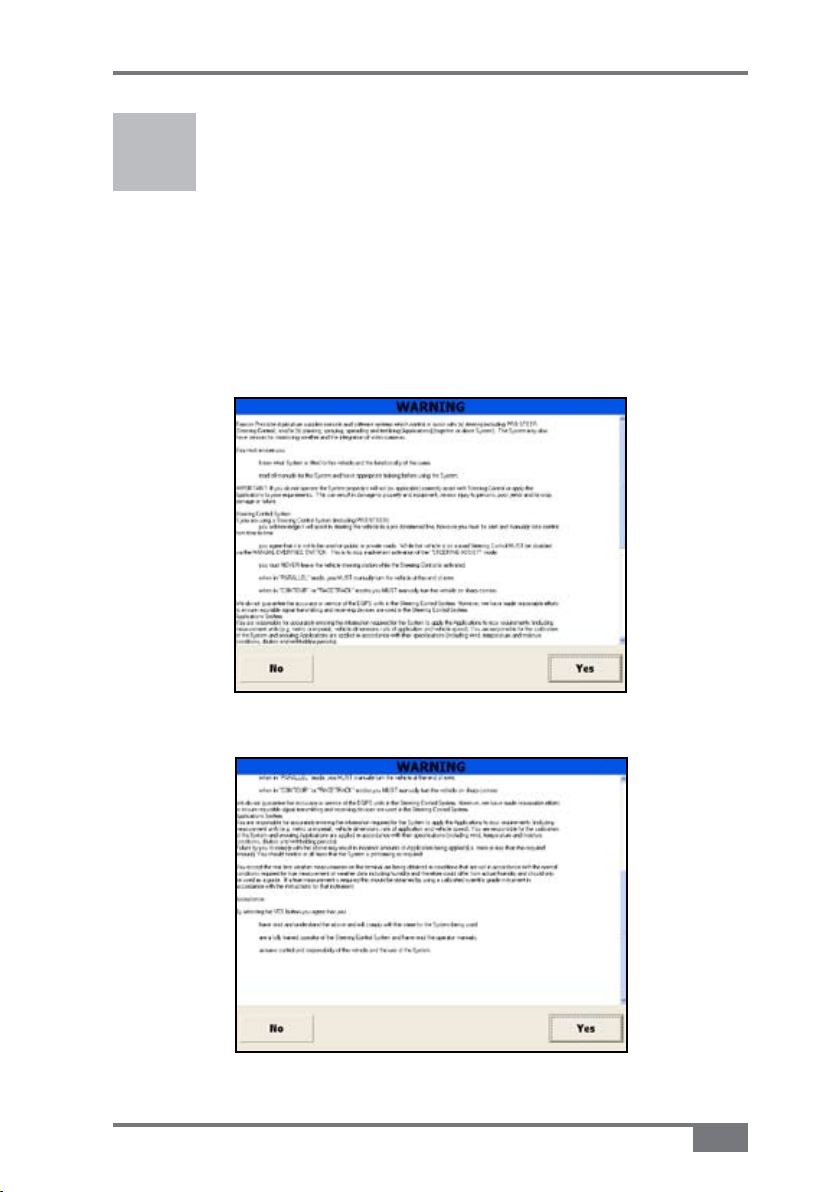
The first window that is displayed when your console starts up is a
Warning page (Figure 6-1 and 6-2).
Figure 6-1. Warning Window Part I
Figure 6-2. Warning Window Part II
A2677 Rev 1.5
6-1
Page 62
X20 Sprayer Reference Manual
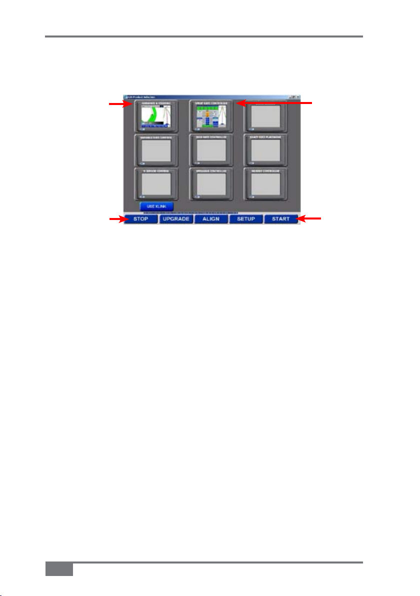
Starting the X20 Console
Guidance
screen icon
Spray
Controller
screen icon
Stop
button
Figure 6-3. X20 Product Selection Screen
Switch the X20 console on by pressing the green 1. Power button
on the rear of the console
Read and understand the warnings (page 6-1) and select 2. Yes to
continue or No to shutdown
Press 3. Stop when the X20 Product Selection screen (Figure 6-3)
is displayed
Start
button
6-2
www.topconpa.com
Page 63

X20 Sprayer Reference Manual
Using Spray Controller Only
Please note: This operators manual assumes that Guidance and
Spray Controller are being used together. To use Guidance and
Spray Controller together see “For use of Spray Controller and
Guidance”, on this page.
Press the 4. Spray Controller screen icon (Figure 6-3 on
page 6-2)
Using Spray Controller and Guidance
Please note: This operators manual assumes that Guidance
and Spray Controller are being used together.
4. Press the Spray Controller screen icon and
Guidance screen icon (Figure 6-3 on page 6-2)
Press the Start button (Figure 6-3 on page 6-2)
The Spray Controller and Guidance (if selected) software will be
loaded.
The Guidance screen (Figure 6-4) (if Guidance was selected) will
be displayed.
Sprayer
icon
Figure 6-4. Guidance Screen Showing
Sprayer Icon
A2677 Rev 1.5
6-3
Page 64

X20 Sprayer Reference Manual
Select the 5. Sprayer icon
The Sprayer Working screen (Figure 6-5) will be displayed.
Please note: If you selected to display the Spray Controller
only then the Sprayer Working screen (Figure 6-5) will be
displayed after Step 4, instead of the Guidance screen (Figure
6-4 on page 6-3).
Sprayer
Menu
Figure 6-5. Sprayer Working Screen
Sprayer
Logo
Options
button
Main Menu
Button
About Spray Rate Controller Window
When the Sprayer Working screen (Figure 6-5) is displayed the
Sprayer Menu (Figure 6-5) will be displayed on the right side of the
screen.
Press the 1. Sprayer Logo (Figure 6-5)
An About Spray Rate Controller window (Figure 6-6 on page
6-5) will be displayed.
6-4
www.topconpa.com
Page 65

X20 Sprayer Reference Manual
Software
Version
Registration
Register
Button
Figure 6-6. About Spray Rate
Controller window
The About Spray Rate Controller window displays:
The Spray Rate Controller • software version number—this
version number may be requested by a Topcon Precision
Agriculture service person.
The Spray ECU version number will be displayed, when the
console is connected to the Spray ECU.
Whether the Sprayer software is • registered or unregistered
The • Enable Lockout button (see "Enable Lockout" page
10-21)
Close • button—when selected the Sprayer Working screen
(Figure 6-5 on page 6-4) will be displayed again.
Close
Button
Registering the Sprayer Software
If the Sprayer software is unregistered you must contact your local
Topcon Precision Agriculture dealer.
A2677 Rev 1.5
6-5
Page 66

X20 Sprayer Reference Manual
Overview of the Sprayer Working Screen
Functions
Front boom
Back boom
Spraying
Indicators
for Front
Line
Pressure
Readout
Manual
Control
Volume
‘Min. Flow’
or Nozzle
Min Flow
indicator
Spraying Indicators
Boom Sections (ON/OFF)
-Up to 30 sections
Switches
all boom
sections
ON /OFF
Returns to
the Main Menu
screen
for Back Line
Figure 6-7. Sprayer Working screen
Main Menu
Screen
Ground
Speed
Sub total area
Tank Indicator
Sub-total
volume (or
weight)
Automatic
Control
Activates all
data on the
right side
of the screen
Displays
number
6-6
Tank
Displays products being applied
Displays volume left in Tank 1
Displays volume left in Tank 1 graphically
Displays Application Rate units
Current Application Rate
Increase the rate on the go
Preset Rate 1
Preset Rate 2
Decrease the Rate on the go
www.topconpa.com
Page 67

X20 Sprayer Reference Manual
• Boom Sections—displays the number of Boom Sections selected.
If Dual line is selected (see "Lines", page 8-25) dual boom
is shown, showing the front and back lines; the top line
representing the front line and the bottom line representing the
back line.
If Single line is selected (see "Lines", page 8-25) then only a
single line of sections will be displayed.
The Boom Sections are numbered starting from the left side of
the spray line, with the far left Section Valve being section valve
‘1’.
The Boom Sections can be switched ON/OFF, either by touching
the Boom Section on the Sprayer Working screen (Figure 6-7)
on page 6-6) or by switching the Boom Sections switches ON/
OFF on the External Switchbox.
Table 6-1 shows what different color Boom Sections and
Spraying Indicators indicate about their status.
Boom Sections and Spraying Indicators Color Indicators
Boom
Section
A2677 Rev 1.5
Spraying
Indicator
Table 6-1. Color indicators
Meaning
Boom Sections are switched OFF.
Boom Sections are switched ON but the
Low Speed Shutoff speed has not been
reached or Master is OFF
Boom Sections are switched ON, the Low
Speed Shutoff speed has been reached,
ready to start spraying.
Boom Section is ready for spraying but
Master Switch is OFF.
Master Switch is ON and Boom Section
valve is spraying.
6-7
Page 68

X20 Sprayer Reference Manual
Please note: When using Automatic Section Control (ASC), when
the sections are switched OFF, the Boom Sections and the Spray
Indicators turn grey; when the sections are switched ON, under ASC
the Boom Sections and Spray Indicators turn green.
• Spraying Indicators— are displayed below the Boom Sections
On the Sprayer Working screen (Figure 6-7 on page 6-6) there
are 16 Spraying Indicators, because there are 16 section valves
in total (8 front Section Valves and 8 back Section Valves). The
8 Spraying Indicators on the left represent the Boom Sections on
the front line, the 8 Spraying Indicators on the right represent the
Boom Sections on the back line.
Table 6-1 on page 6-7 displays and explains the different states
of the Spraying Indicators. Table 6-2 shows what different color
Spraying Indicators indicate about their status.
Spraying
Indicator
Spraying Indicators Color Indicators
Meaning
Boom Section is not spraying.
Boom Sections is spraying.
Table 6-2. Spraying Indicators Color Indicators
• Auto—when selected (by selecting Auto on the Switchbox
or Sprayer Working screen) the AUTO button will become
highlighted and a green indicator will be shown in the AUTO
button
When AUTO is selected the Spray Controller automatically
adjusts the flow, according to speed, width or number of sections
that are ON..
6-8
www.topconpa.com
Page 69

X20 Sprayer Reference Manual
• Manual—when selected (by selecting Manual on the Switchbox
or MANUAL from the Sprayer Working screen) the MANUAL
button will become highlighted and a green indicator will be
shown on the MANUAL button
When MANUAL is selected the Spray Controller does not
automatically adjust the flow, according to speed and area.
Pressing the INC & DEC buttons will increase or decrease the
pressure by opening or closing the regulator valve.
• Pressure Readout—displays the system pressure if an electronic
Pressure Sensor is installed and selected in Options, see
"Pressure (Pr) Sense", see "Pressure Sensor", page 8-15
The number in the top left corner indicates which tank (1,2 or 3)
the pressure readout is from.
Selecting the Pressure Readout button displays a Tank Pressure
window on the right of the screen, see "Pressure Sensor", page
10-1.
• Volume—displays volume per minute (for the front line) or
volume per nozzle (for the front line nozzles), depending on
which was selected, see "Flow", page 10-6
Selecting the Volume button displays a Flow window, on the
right side of the screen, see "Flow", page 10-6.
• Pump is On—this button only appears when the Spray ECU,
Prop. Valve and Enable Pump Control buttons are all selected
When selected the button says PUMP is ON and turns green; this
switches the hydraulic pump ON.
When selected again the button says PUMP is OFF and turns
red; this switches the hydraulic pump OFF.
A2677 Rev 1.5
6-9
Page 70

X20 Sprayer Reference Manual
• Ground Speed—displays the actual ground speed, whether it is
from the Wheel Sensor, tractor radar or GPS, depending on what
is selected, see "Speed From", page 8-8
Selecting the Ground Speed button displays a Speed window on
the right side of the screen, see "Speed", page 10-8.
• Sub Total (Area)—readout displays the area sprayed for the sub
area selected, depending on the units selected, see "Units", page
8-55
The number in the top left corner of the readout displays the
current sub area number. There are 10 sub area numbers (0-9).
Selecting the Sub Total Area button displays an Area window
on the right side of the screen, see "Area/Volume", page 10-10.
• Sub Total (Volume Used)—readout displays the volume
(or weight) sprayed for the sub area selected, depending on the
units selected, see "Units", page 8-55
The number in the top left corner of the readout displays the
current sub area number. There are 10 sub area numbers (0-9).
Selecting the Sub Total Volume button displays an Area window
on the right side of the screen, see "Area/Volume", page 10-10.
• Tank Indicator—only appears when more than 1 tank is selected
in Options
This allows the Sub Total Area and Sub Total Volume to be
displayed for each tank.
To change which tank is displayed select either the Sub Total
Area button or Sub Total Volume button (Figure 6-7 on page
6-6). You will notice the orange Tank Indicator will change each
6-10
www.topconpa.com
Page 71

X20 Sprayer Reference Manual
time the readouts are selected.
• Pump Speed—this displays the actual pump speed. The Pump
Speed readout is only displayed if Enable Pump Speed
Indicator is selected in Options, see "Pump Options", page 8-52
Min. Flow or Nozzle Min. Flow Indicator• —a red indicator will
be displayed in the Volume readout (Figure 6-7 on page 6-6)
when the minimum flow for the Regulator Valve is reached, or
the minimum flow for the nozzles is reached.
Select the Volume button to see the reason the red indicator
is being displayed. The reason will be displayed in the Flow
window on the right side of the screen, see "Flow", page 10-6.
Sprayer Logo
Options
Help
Shut down
Figure 6-8. Main Menu screen
A2677 Rev 1.5
6-11
Page 72

X20 Sprayer Reference Manual
• Sprayer Logo—when selected information about your Sprayer
will be displayed, see “About Spray Rate Controller Window”,
page 6-4.
• Options—when pressed the Options window will open.
The Options window is where the Sprayer settings can be
entered, see “Setting Up the Software”, Chapter 8.
• Help—displays the on screen help.
• Shutdown—when selected returns the operator to the Windows
Desktop or turns OFF the console.
6-12
www.topconpa.com
Page 73

X20 Sprayer Reference Manual
NOTICE
Conguration Setup
Current
Configuration
Figure 7-1. Conguration Screen
Slide
Audio
Volume
Press 1. Options (Figure 6-8 on page 6-12).
The Configuration screen (Figure 7-1) will be displayed.
NOTICE
Complete the installation of the Sprayer before
setting up the software and applying settings.
A2677 Rev 1.5
7-1
Page 74

X20 Sprayer Reference Manual
Audio Volume
In the Audio Volume window the operator can set the desired audio
level.
Setting the Audio Volume
Select and hold down the slide and slide it up or down, until 1.
the desired audio volume is achieved.
Configuration
The Configuration screen contains two configuration windows (Figure
7-1 on page 7-1):
Change Current Configuration •
Load Configuration •
Change Current Configuration
The Change Current Configuration window has 2 buttons:
• Change/View Configuration—This button allows the operator
to view the settings of the current Sprayer, loaded from either
the Factory Configuration or User Configurations
• Save As User Configuration—This is used to save the current
Sprayer settings, see "Saving the Sprayer Configuration",
Chapter 9.
Load Configuration
The Load Configuration window has 2 buttons:
• Factory Configuration—The Factory Configurations
button opens a list of Sprayer models and Topcon Precision
Agriculture Sprayer kits
7-2
www.topconpa.com
Page 75
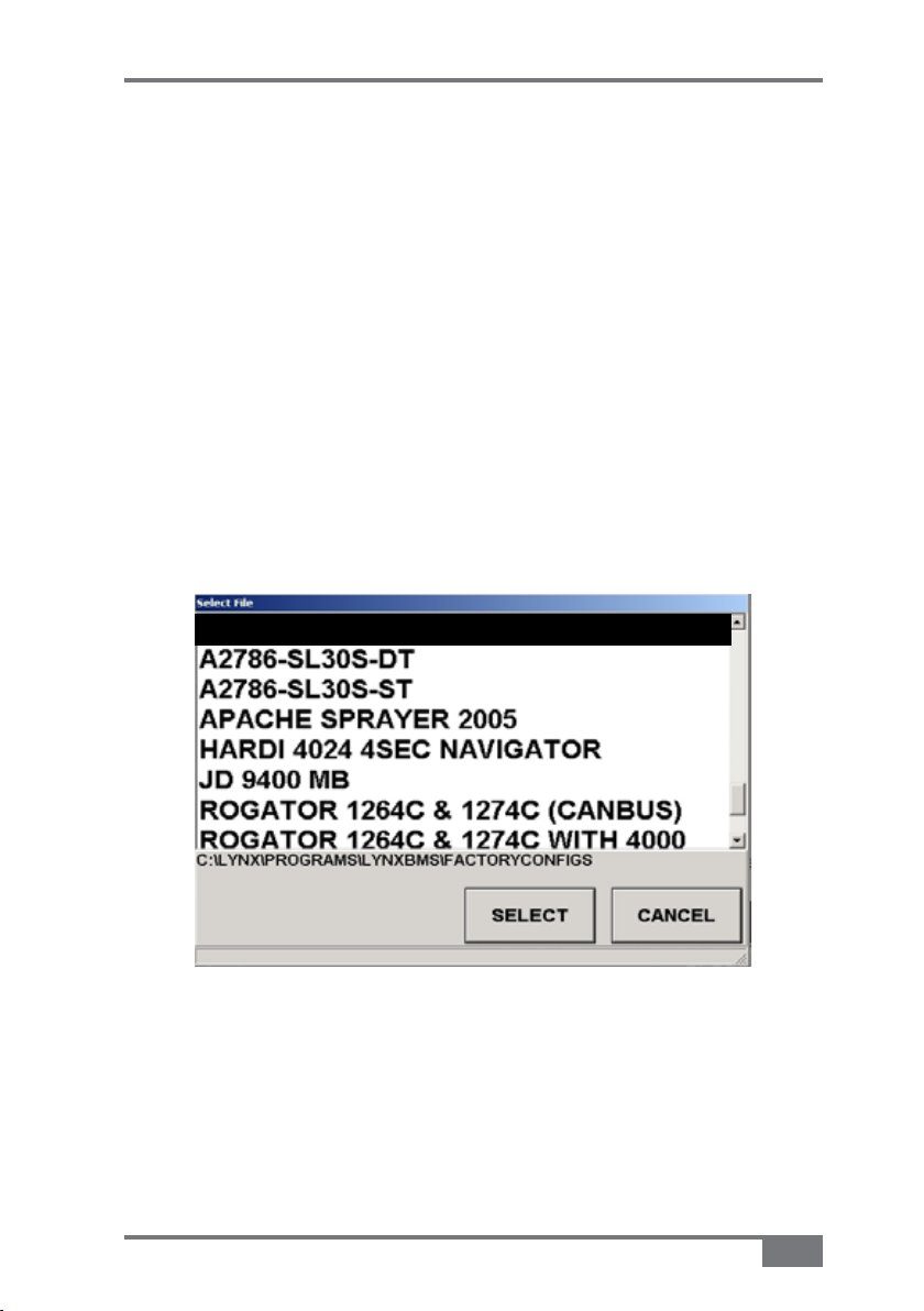
X20 Sprayer Reference Manual
The files contain all the Sprayer settings for the particular
Sprayer.
The Factory Configuration files are pre-loaded with the
console or new Sprayer software.
When the operator selects the Factory Configurations
button all the settings for that particular Sprayer model are
loaded in the Options windows.
Selecting a Factory Configuration File
Select the 1. Factory Configurations button
The Select File window (Figure 7-2) will be
displayed.
A2786-DL15S-ST
Figure 7-2. Select File Window
A2677 Rev 1.5
Check to see if your Sprayer or TPA Sprayer kit is 2.
listed on the list shown in the Select File window
(shown in Figure 7-2)
7-3
Page 76

X20 Sprayer Reference Manual
If your Sprayer is listed:
3. Select the Sprayer, by touching the name
This will highlight the option you have chosen.
4. Press Select (Figure 7-2 on Page 7-3), to load
the Sprayer configuration
A window will appear confirming that the Sprayer
you selected in Step 3 will be loaded.
5. Select Yes, to load the settings for the selected
Sprayer
OR
Select No to stop loading the selected Sprayer
If you selected Yes the Sprayer Configuration
will be loaded and listed under Current Configuration
(Figure 7-3).
7-4
Figure 7-3. Conguration Showing
Selected Sprayer Kit
www.topconpa.com
Page 77

X20 Sprayer Reference Manual
If your Sprayer is not listed:
3. Press the Cancel button (Figure 7-2 on page
7-3).
This will close the Select File window.
4. Go to “Change/View Configuration Button”, page 7-8
to proceed.
• User Configuration—The User Configurations list can be
changed any time the Sprayer settings are changed; the
operator will be prompted to overwrite the file or select a
new file.
The operator can have all their different Sprayers saved in the
User Configurations list and these Sprayers can be recalled at
any time.
A2677 Rev 1.5
7-5
Page 78

X20 Sprayer Reference Manual
Setup
Once a Sprayer or Sprayer kit is selected then most of the Sprayer
values and settings will be loaded into the Sprayer software Options
and you will only have to enter a few values (eg. Section Widths, Unit
type, Wheel Calibration Factor) to get started.
You must choose one of two options:
Go to "Setting Up the Software", Chapter 8 of the Software •
Setup and work through the manual, which outlines all the
Sprayer options within the software
OR
Use the Quick Setup Guide (below) and enter in the Sprayer •
settings which are unique to your Sprayer.
Quick Setup Guide
7-6
Select the 1. Change/View Configuration button
This will allow you to view the settings of the Sprayer that was
loaded.
For help with understanding and navigating the Options
windows see Appendix A.
Select the COM Port the Spray ECU is connected to on the 2.
back of the console, on the ECU page, see page 8-6
Enter the Tank Capacity of the Sprayer, on the 3. Tanks page, see
page 8-13
Change the number of sections if they are different to the ones 4.
displayed on the Sections page, see page 8-26
www.topconpa.com
Page 79

X20 Sprayer Reference Manual
Check the number of Guidance sections used, in the 5. Guidance
window, and change if necessary, see page 8-28
Enter the swath width of the Spray Boom, on the 6. Sections
page, by entering in the Section widths of each of the Boom
Sections, see page 8-25
Enter the number of nozzles on each Boom Section, on the 7.
Sections page, see page 8-28
Enter the Minimum Flow value of the nozzles fitted to the 8.
Spray Line, on the Sections page, check nozzle chart, see page
8-29
Enter the Flow Calibration factor for the Flow Meter, on the 9.
Sensors page, see page 8-39
Enter the Flow Meter's Minimum Flow value, check the Flow 10.
Meter’s specifications, on the Sensors page, see page 8-40
Enter the Wheel Calibration, on the 11. Setup page, see page 8-46
You may change the Units, on the 12. Units page, to suit your
preferences, see page 8-55
Save changes to the User Configuration, see Chapter 913.
A2677 Rev 1.5
7-7
Page 80

X20 Sprayer Reference Manual
Notes:
7-8
www.topconpa.com
Page 81

Conguration
GPS
X20 Sprayer Reference Manual
Figure 8-1. Options>GPS Page
Please note: The GPS page is only displayed if Guidance and/or
Variable Rate Control (VRC) are selected with Spray Rate Control, on
the Product Selection screen.
If Guidance and/or VRC are not selected on the Product Selection
screen, the ECU page (page 8-6) will be the first to be displayed.
Automatic Section Control (ASC)
ASC can only be Enabled when DGPS is used in conjunction
with Guidance. This feature will automatically switch sections on
the Sprayer ON and OFF, therefore preventing the Sprayer from
overlapping or under lapping previously sprayed areas.
A2677 Rev 1.5
8-1
Page 82

X20 Sprayer Reference Manual
NOTICE
The ASC option in Guidance General Setup must also be selected
(see X20 Guidance manual Page 4-21 Chapter 4).
Select Off (Figure 8-1 on page 8-1) if Guidance is not working.
Variable Rate Control (VRC)/Logging Mode
If you are not using VRC or Logging select Off (Figure 8-1 on
page 8-1).
Select Logging Only if you are not using a VRC prescription
map but are logging the Spray Rate’s elevation mapping, using the
Maplink VRC software. This allows logging to be done without
loading a VRC prescription map.
Select VRC and Logging if using the Maplink VRC software,
to load a VRC prescription map to control the Spray Rate to a
region based map. A VRC Master button will be displayed on the
Guidance and Maplink VRC screens.
The only difference between Logging Only and VRC and Logging,
is when Logging Only is selected, the VRC Master button is
removed from the Guidance screen, to prevent confusion.
NOTICE
When selecting Logging Only and VRC and Logging,
Variable Rate Control (Maplink VRC) must be
selected in the Product Selection screen during
startup.
(VRC)/Logging Synchronization
When Logging Only and VRC and Logging are selected, then the
VRC/Logging Synchronization window will be displayed.
8-2
www.topconpa.com
Page 83

X20 Sprayer Reference Manual
NOTICE
Select Off if you want to be able to switch the Treatment button
ON and OFF (on the VRC [Maplink] screen), independently of the
Sprayer Master Switch.
Select Master Switch Only for the logging in the VRC to follow
the Master Switch.
Master ON means that logging is ON and Master OFF means that
logging is OFF.
Master Switch and Flow is usually selected when ASC is
enabled, see “Automatic Section Control (ASC)”, page 8-1.
If all the sections are switched OFF under ASC, but the Master
is still ON the logging will stop because there is no flow present.
Therefore logging will stop if all the sections are switched OFF, the
Master is switched OFF or the actual spray rate is ‘0’.
NOTICE
When using Spray Rate Controller Version 1.98 or
later with X20 Guidance the On Time and Off Time
options are inaccessible in the X20 Guidance and
the values have to be entered in the Spray Rate
Controller Options>GPS page.
On Time
On Time is the time the Sprayer looks ahead (in seconds) to switch
ON the section valves.
Change the ON Time by pressing the calculator icon and entering
the desired value, see Appendix A for more detail.
A2677 Rev 1.5
8-3
Page 84

X20 Sprayer Reference Manual
Off Time
Off Time is the time the Sprayer looks ahead (in seconds) to switch
OFF the section valves.
Change the OFF Time by pressing the calculator icon and entering
the desired value, see Appendix A for more detail.
Coverage Map Offset
Coverage Map Offset allows for the coverage in the Guidance and
Treatment maps in the Maplink software to keep drawing for the
set time after the Spray Control turns the section valves OFF and
also when the section valves are switched ON.
This feature allows for no gaps to be left on the map.
Change the Covergae Map Offset by pressing the calculator icon
and entering the desired value, see Appendix A for more detail.
Show Virtual Road If Moving
When the Show Virtual Road If Moving option is selected the
Guidance Virtual Road will appear on the right side of the screen
when Guidance detects that the vehicle is moving.
ASC Master Button
The ASC Master button will appear on the logo Bar on the
Guidance Working screen. The ASC Master button will also be
displayed on the VRC screen, if the VRC software is loaded.
This button will be displayed when both Guidance and Spray
Rate Controller are selected from the Product Selection screen
and ASC is enabled in the Sprayer Software
When the ASC Master button is green ASC is switched ON.
When the ASC Master button is red ASC is switched OFF, and
8-4
www.topconpa.com
Page 85

X20 Sprayer Reference Manual
Guidance will not switch section valves ON and OFF by the
Coverage map.
The operator can override the sections by using the section
switches on the external Switchbox or on screen section switches
of the Spray Rate Controller.
Select the button to switch the ASC Master ON or OFF.
ASC will only operate with software that is compatible with
Guidance. Some other makes of controllers will interact with the
TPA software. Speak to your dealer for more information.
VRC Master Button
The VRC Master button will appear on the logo Bar on the
Guidance and Maplink screens when VRC and Logging option is
enabled in the VRC/Loggingn mode window.
When the VRC Master button is green VRC is switched ON.
When the VRC Master button is red VRC is switched OFF.
Select the button to switch the VRC Master ON or OFF.
A2677 Rev 1.5
8-5
Page 86

X20 Sprayer Reference Manual
NOTICE
Electronic Control Unit (ECU)
Figure 8-2. Options>ECU Page
COM Port
Select which Communications Port (COM Port) the 9 pin serial
cable from the Spray Rate Controller ECU is connected on the
back of the X console.
Usually COM2 is selected.
COM 1 is usually reserved for the Guidance GPS or DGPS
receiver.
NOTICE
If the COM Port is changed or selected you must
restart the software.
8-6
www.topconpa.com
Page 87

X20 Sprayer Reference Manual
Simulation is selected for desktop use when the console is not
connected to the Spray ECU. This disables all the alarms.
The COM Ports are greyed out if the Spray Rate software is not
registered, contact Topcon to register your software.
Controller
Select Spray Interface if one of the following is written on the
Spray Rate Controller:
KEE Spray Rate Interface •
ZYNX 5500 Interface •
ZYNX 2500 Interface •
Select Spray ECU if Spray ECU is written on the Spray
Controller.
If Spray ECU was selected see pages 8-10, 8-33, 8-42 and 8-53
also.
Using Injection ECU
Before selecting Using Injection ECU an additional Chemical
Injection pump has to be purchased and an additional Multi Drive
Electronic Control Unit (MDECU) and harnesses would also be
required.
This option, with the appropriate hardware will allow all the Spray
ECU’s to control up to 3 injection tanks if connected to a 4 channel
MDECU.
Please note: A Supplement Manual will be required to install the
Chemical Injection Pump.
A2677 Rev 1.5
8-7
Page 88

X20 Sprayer Reference Manual
NOTICE
Speed From
For Speed From select from one of the three options:
• Wheel Sensor
• Tractor Radar
• GPS.
Spray Interface
If Spray Interface was selected as the controller (page 8-7):
Select • Wheel Sensor if a ground speed sensor is connected
to the spray harness plug marked Wheel Sensor (usually
located on the Spray Harness)
Select • Tractor Radar if connecting a Tractor Radar to the
spray interface
The Tractor Radar plugs into the 3-pin weatherpack plug
marked Tractor Radar on the spray interface.
8-8
Select• GPS if the speed is coming from a DGPS receiver.
NOTICE
Guidance (or Maplink VRC) and Spray Rate Control
must be selected from the Product Selection screen
before GPS is selected.
www.topconpa.com
Page 89

X20 Sprayer Reference Manual
NOTICE
Spray ECU
If Spray ECU was selected as the controller (page 8-7):
Select • Wheel Sensor if a ground speed sensor is connected
to the spray harness plug marked Connector 1 on the Spray
ECU
The wheel sensor is usually located on the boom spray.
The Raven Spray ECU 3 and Spray ECU/SR has a 3-pin •
weatherpack plug marked Radar on the Spray ECU 3, if a
Radar is connect to this plug select Tractor Radar
Select • GPS if the speed is coming from a DGPS receiver.
NOTICE
Guidance and Spray Rate Control must be selected
from the Product Selection screen before GPS is
selected.
A2677 Rev 1.5
8-9
Page 90

X20 Sprayer Reference Manual
ECU Configuration (Spray ECU Only)
Figure 8-3. Options>ECU Page>
ECU Conguration
The ECU Configuration window (Figure 8-3) will only be
displayed when Spray ECU is selected as the controller
(page 8-7).
ECU Model
8-10
Select • ECU, ECU3 if the description on the overlay reads
either ‘Spray ECU’, ‘Spray ECU 3’ or ‘Hardi 5500 Spray
ECU’
The corresponding art number on the Spray ECU is either
A2036, A2445 or A2243.
Select • ECU 10S, ECU 10SR if the description on the
overlay reads ‘Spray ECU 10S’ or ‘Spray ECU 10SR’
The corresponding part number on the Spray ECU is
A2644.
www.topconpa.com
Page 91

X20 Sprayer Reference Manual
Select • ECU 30S if the description on the overlay reads
‘Spray ECU 30S’.
The corresponding part number is A2643.
Please note: The ECU models: ECU and ECU 3 will come
factory loaded with the firmware version BMS207 or higher.
The ECU models ECU 10S, 10SR and 30S will come factory
loaded with firmware version BMS 209 or higher.
Section Valve Mode
Select • 3 wire/Solenoid if the Sprayer is fitted with 3 Wire
Motorized Section Valves or Solenoid Section Valves.
Please note: When 3-Wire/Solenoid is selected the Sprayer
can control 31 Section Valves and one 3-Wire Dump Valve.
This is because both 3-Wire Motor Valves and Solenoids
only require a single signal wire to switch the valves ON
and OFF. Therefore, 31 sections can be selected. The
current harness only support 30 sections.
A2677 Rev 1.5
Select • 2 wire if the Sprayer is fitted with 2-Wire Motorized
Section Valves (Reverse Polarity Valves).
Please note: When 2 wire is selected (2 wire Motorized
Valves of Reverse Polarity Valves) this enables the Sprayer
to control 15 section valves and one 2 wire Dump Valve,
because 2 wire valves require 2 signal wires to switch the
section valves ON or OFF. Therefore, only 15 sections can
be selected.
8-11
Page 92

X20 Sprayer Reference Manual
Select • 2 wire + power save if the Sprayer is fitted with
2 wire Motorized Section Valves and the power saving
feature is required. If the section valves do not receive a
signal from the controller for 2 minutes the power to the
section valves is switched OFF, this conserves power.
Please note: The 2 wire + power save feature is only
supported on Spray ECUs with firmware version 209 or
higher.
Dump Valve Mode
If 3 wire/Solenoid was selected from Section Valve Mode
(page 8-12) then select:
• Not used—if no Dump Valve is fitted to the Sprayer
• 2 wire—if fitting a 2 wire Dump Valve to the Sprayer
• 3 wire—if fitting a 3 wire Dump Valve to the Sprayer.
If 2 wire or 2 wire + power save was selected from Section
Valve Mode (page 8-12) then select Not used.
Please note: When 2 wire section valves are fitted to the Sprayer
then only a 2 wire Dump Valve can be fitted to the Sprayer; a 3
wire Dump Valve is not an option.
8-12
www.topconpa.com
Page 93
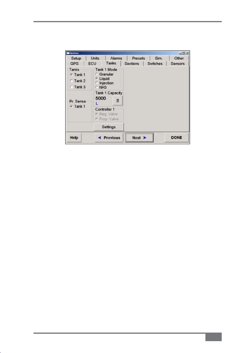
X20 Sprayer Reference Manual
Tanks
Figure 8-4. Options>Tanks Page
Tanks
Select the appropriate tanks for your Sprayer. Most Sprayers will
only have one tank. Therefore select Tank 1 only.
Please note: If any of the Spray ECUs have the appropriate
Chemical Injection Pump hardware installed with a 4 channel
MDECU and the Using Injection ECU option selected (page 8-7)
then up to 3 tanks may be selected.
If more than 1 tank is selected then Tank 2 Mode and/or Tank 3
Mode will appear next to Tank 1 Mode.
If more than 1 tank is selected then Pr. Sense for Tank 2 and/
or Tank 3 will appear; also additional Capacity and Controller
windows will appear.
A2677 Rev 1.5
8-13
Page 94

X20 Sprayer Reference Manual
Tank 1 Mode
Tank 1 Mode selects the appropriate units depending on which
mode is chosen, ie: when Liquid is selected then the units are set
to ‘Litres’, ‘L/Ha’ and Flow Sensor to ‘pulses per litre’ (if metric
units is selected, see page 8-55). For imperial units, the units could
be replaced with 'Gallons', 'Gallons/Acre' and Flow Sensor to
'Pulses per Gallon'
Tank Mode is normally set to Liquid for spraying.
Select Granular if using the Spray Rate Controller as a spreader
controller.
Select Injection if the Spray system has a Chemical Injection
Pump and a 2 or 4 channel MDECU installed.
Select NH3 if connecting the Spray Rate Controller to an
Anhydrous Gas Tank.
If Tank 2 or Tank 3 was selected in the Tanks window (page 8-13)
select the Tank Mode for each of these tanks in the appropriate
windows.
Controller 1
If Spray Interface is selected as the controller, then only Reg.
Valve (Regulator Valve) can be selected and that is why the option
is greyed out and no selection is possible.
If Spray ECU is selected as the controller, then either Reg. Valve
or Prop. Valve (Proportional Valve) can be selected. Depending
on whether the type of controller is Regulator or Proportional.
Select the Settings button (Figure 8-4 on page 8-13) to personalize
the Controller settings. See “Regulator Valve Settings”, page 8-16
if Reg. Valve is selected or “Proportional Valve Settings”, page
8-21 if Prop. Valve is selected.
8-14
www.topconpa.com
Page 95

X20 Sprayer Reference Manual
Pressure (Pr) Sense
The Spray Rate Controller can monitor the pressure in a spray
system, which is displayed as a Pressure readout on the Working
screen (Figure 6-7 on page 6-7). The Spray Rate Controller uses
Flow to control.
Low and high pressure alarms can be set, to alert the operator
when the pressure in the system goes above the high alarm point or
below the low alarm point, see “Alarms”, 8-57.
Select Tank 1 if an electronic Pressure Sensor is fitted to the
Sprayer, otherwise leave deselected. See page 8-38 or 8-42 (for
Spray ECU configuration) to select the type of electronic Pressure
Sensor fitted to the system.
If more than 1 tank was selected in the Tanks window then a
Pressure Sensor can be selected for each tank that has a Pressure
Sensor present.
A2677 Rev 1.5
8-15
Page 96

X20 Sprayer Reference Manual
Regulator Valve Settings
Figure 8-5. Regulator Valve Settings
The Regulating Valves and their settings are critical for the correct
operation of the Sprayer, particularly if Automatic Section Control
(ASC) is to be used.
To have good control when using ASC a faster Regulator Valve
may need to be installed. A 20 second KZCO Valve will be
sluggish and give poor control when using ASC and should
be updated to the 6 second ARAG Valve (grey band) or faster
Regulator Valve. 6 seconds represents the time for the Reg Valve to
go from fully closed to fully open.
When a Controller mode is selected then the Max On Time, PWM
Setting, Min On Time and Gain Setting settings are automatically
set. These settings can then be fine tuned manually.
Controller Mode
Select one of the following options:
• Standard—will account for most regulating valve types
available in the market. Standard mode takes into account
8-16
www.topconpa.com
Page 97

20 sec.
or higher
Reg valve
Eg:: TPA
KZCO
16 sec.
Reg valve
Eg:: Arag
Yellow
Band
Hardi Reg
Valve
Raven
STD Reg
Valve
6 sec. Reg
valve
Eg:: Arag
Grey
Band
X20 Sprayer Reference Manual
regulating valves that take between 4 and 20 seconds to go
from fully closed to fully open. Check the specifications of
the regulator fitted valve fitted to the Sprayer
Examples include Topcon (aka KEE) KZCO, Arag
Yellow band, Hardi, Raven Standard and Arag Grey band
Regulator Valves.
If Standard is selected you will have to select the
Regulator Valve that best suits your Regulator Valve from
Table 8-1 and enter the settings from the table into the Max
On Time, PWM Setting, Min On Time and Gain Setting
windows.
Settings for Common Regulator Valves
Controller Max On Time PWM Setting Min On Time Gain Setting
Standard 4.0 sec. 100% 8 msec. 16ms/%
Standard 4.0 sec.
100%
8 msec.
16ms/%
Standard 4.0 sec. 100% 8 msec. 16ms/%
Standard 4.0 sec.
100% 8 msec. 16ms/%
Standard 2.0 sec.
100% 2 msec. 16ms/%
Table 8-1. Settings for Common Regulator Valves
A2677 Rev 1.5
8-17
Page 98

X20 Sprayer Reference Manual
• Micro-Trak—should be selected if a Micro-Trak Regulator
Valve is used for regulation. When Micro-Trak is selected
the settings are entered automatically into the Max On
Time, PWM Setting, Min On Time and Gain Setting
windows and are optimized for the Mictro-Trak Regulator
Valve
• DICKEY-john—should be selected if a DICKEYjohn Regulator Valve is used for regulation. When
DICEKY-john is selected the default settings are entered
automatically into the Max On Time, PWM Setting, Min
On Time and Gain Setting windows and are optimized for
the DICKEY-john Regulator Valve
• Raven—should be selected if the Sprayer has Raven Fast
Flow Regulator Valve fitted, unless a Topcon Pressure
Relief (495181) has been fitted to the Raven Fast Flow
Regulator Valve.
The Raven Fast Flow has a three way valve which acts as
both a regulator and dump valve. The valve will go from
fully closed to fully open in 1.5 seconds. The PWM Setting
must be left on full (100%) otherwise this will impair
the operation of the Dump Valve and Automatic Section
Control.
If Raven is selected you will have to enter the settings
from Table 8-2 (page 8-19) into the Max On Time, PWM
Setting, Min On Time and Gain Setting windows.
8-18
www.topconpa.com
Page 99

X20 Sprayer Reference Manual
CAUTION
Settings for Raven Controller Mode
Controller Max On Time PWM Setting Min On Time Gain Setting
Raven
Fast Flow
Reg valve
(1.5 sec.)
Raven 40 msec. 100% 8 msec. 2.4ms/%
Table 8-2. Settings for Raven Controller Mode
CAUTION
When using a Raven Regulator that operates as
a Dump Valve then you must select the Close
Valve When Flow Off option. Failure to do this
could dead end the system and cause damage to
pumps, hoses etc.
See "Service Bulletins", Chapter 7 if a positive
displacement (piston or diaphragm) pump and a
Raven Fast Flow Regulator Valve are fitted.
TPA recommends a Pressure Relief kit (495181)
to be fitted to the Sprayer. If the kit is fitted then
follow the settings recommended in the Service
Bulletin.
A2677 Rev 1.5
8-19
Page 100

X20 Sprayer Reference Manual
TIP
Reverse Valve Direction
All Regulator Valves have a two wire control system. Polarity is
reversed to change the direction of the regulator when in use.
Select Reverse Valve Direction if the valve is turning in the
wrong direction, ie: pressure is being increased when the
decrease button is selected on the Working screen.
Close Valve When Flow Off
Select this option if using a 3 way Regulator Valve, which also
operates as a Dump Valve, such as the Raven Fast Valve.
Also select this option if Anhydrous Gas is being used through
the regulator.
Sensitivity
The Sensitivity setting refers to the Flow Meter signal and may
need to be set to Reduced to stop ‘hunting’. This setting will also
make the response to rate changes sluggish.
8-20
TIP
It is recommended that Standard is selected.
www.topconpa.com
 Loading...