

Page 1

Wheel Loader
3D-MC
Installation and Calibration Manual
For more information contact Synergy Positioning Systems or
visit the Synergy Positioning Systems website at www.synergypositioning.co.nz
All branches: Phone 0800 867 266 Email: info@synergypositioning.co.nz
Page 2

Page 3

Wheel Loader
3D-MC
Installation and Calibration Manual
©Copyright Topcon Positioning Systems, Inc.
Topcon Positioning Systems, Inc. All rights reserved. The information contained herein may not be used, accessed, copied, stored,
displayed, sold, modified, published or distributed, or otherwise reproduced without express written consent for Topcon.
Part Number 7010-1006
Revision B
August, 2018
Page 4

Preface . . . . . . . . . . . . . . . . . . . . . . . . . . . . . . . . . . . . . . . . . . . . . . . . . . . . iii
Table of Contents
Introduction
System Components—Hardware and Software . . . . . . . . . . . . . . . . . . . . . . . 1-1
Sensor Angles . . . . . . . . . . . . . . . . . . . . . . . . . . . . . . . . . . . . . . . . . . . . . . . . 1-3
Basic Cable Connections. . . . . . . . . . . . . . . . . . . . . . . . . . . . . . . . . . . . . . . . . 1-3
. . . . . . . . . . . . . . . . . . . . . . . . . . . . . . . . . . . . . . . . . . . . . . . . . . . . . . . . . . . . 1-1
Installation . . . . . . . . . . . . . . . . . . . . . . . . . . . . . . . . . . . . . . . . . . . . . . . . 2-1
Tilt Sensor Installation . . . . . . . . . . . . . . . . . . . . . . . . . . . . . . . . . . . . . . . . . . 2-1
TS-i3 Sensors . . . . . . . . . . . . . . . . . . . . . . . . . . . . . . . . . . . . . . . . . . . . . . . . 2-1
TS-i3 Sensor Orientation . . . . . . . . . . . . . . . . . . . . . . . . . . . . . . . . . . . 2-1
Attachment/Bucket Sensor Installation . . . . . . . . . . . . . . . . . . . . . . . . . . . . . 2-2
Non Quick Release Attachment/Bucket Sensor Installation. . . . . . . . . . . . . . . . . 2-3
Quick Release Attachment/Bucket Sensor Installation . . . . . . . . . . . . . . . . . . . . 2-4
Boom Sensor Installation . . . . . . . . . . . . . . . . . . . . . . . . . . . . . . . . . . . . . . . . 2-5
Body Sensor Installation . . . . . . . . . . . . . . . . . . . . . . . . . . . . . . . . . . . . . . . . . 2-6
GNSS Antenna, Mount, and Mast Installation . . . . . . . . . . . . . . . . . . . . . . . . 2-7
Machine Setup and Configuration . . . . . . . . . . . . . . . . . . . . . . . . . . . . . . 3-1
Entering Sensor Information . . . . . . . . . . . . . . . . . . . . . . . . . . . . . . . . . . . . . . 3-1
Taking Machine Measurements . . . . . . . . . . . . . . . . . . . . . . . . . . . . . . . . . . . . 3-1
Entering Sensor Information . . . . . . . . . . . . . . . . . . . . . . . . . . . . . . . . . . . . . . 3-4
Light Bars . . . . . . . . . . . . . . . . . . . . . . . . . . . . . . . . . . . . . . . . . . . . . . . . . . . . . 3-9
Machine Configuration Complete . . . . . . . . . . . . . . . . . . . . . . . . . . . . . . . . . . 3-9
Calibration . . . . . . . . . . . . . . . . . . . . . . . . . . . . . . . . . . . . . . . . . . . . . . . . . 4-1
Body Sensor Calibration. . . . . . . . . . . . . . . . . . . . . . . . . . . . . . . . . . . . . . . . . . 4-1
Boom Sensor Calibration . . . . . . . . . . . . . . . . . . . . . . . . . . . . . . . . . . . . . . . . . 4-3
Attachment/Bucket Sensor Calibration . . . . . . . . . . . . . . . . . . . . . . . . . . . . . 4-4
Attachment/Bucket Edge Sensor Calibration. . . . . . . . . . . . . . . . . . . . . . . . . 4-5
Sensor Filtering . . . . . . . . . . . . . . . . . . . . . . . . . . . . . . . . . . . . . . . . . . . . . . . . 4-6
Safety Warnings . . . . . . . . . . . . . . . . . . . . . . . . . . . . . . . . . . . . . . . . . . . . 5-1
General Precautions. . . . . . . . . . . . . . . . . . . . . . . . . . . . . . . . . . . . . . . . . . . . . 5-1
Radio Usage Information. . . . . . . . . . . . . . . . . . . . . . . . . . . . . . . . . . . . . . . . . 5-2
Usage Warnings . . . . . . . . . . . . . . . . . . . . . . . . . . . . . . . . . . . . . . . . . . . . . . . 5-3
P/N: 7010-1006
ii
Page 5

Preface
Thank you for purchasing this Topcon product. The materials available in this Manual (the “Manual”)
have been prepared by Topcon Positioning Systems, Inc. (“TPS”) for owners of Topcon products, and
are designed to assist owners with the use of the receiver and its use is subject to these terms and
conditions (the “Terms and Conditions”).
Please read the following terms and conditions carefully.
Terms and Conditions
Use
This product is designed to be used by a professional. The user should have a good knowledge of the
safe use of the product and implement the types of safety procedures recommended by the local
government protection agency for both private use and commercial job sites.
Copyrights
All information contained in this Manual is the intellectual property of, and copyrighted material of
Topcon Positioning Systems (TPS). All rights are reserved. Do not use, access, copy, store, display,
create derivative works of, sell, modify, publish, distribute, or allow any third party access to, any
graphics, content, information or data in this Manual without TPS’ express written consent and may only
use such information for the care and operation of the receiver. The information and data in this Manual
are a valuable asset of TPS and are developed by the expenditure of considerable work, time and
money, and are the result of original selection, coordination and arrangement by TPS.
Trademarks
Top co n®, Topcon Positioning Systems™, 3D-MC® are trademarks or registered trademarks of TPS.
GX-55, GX-75, MC-i4, TS-i3 are trademarks of TPS. Windows
Corporation. The Bluetooth
such marks by Topcon Positioning Systems, Inc. is used under license. Other product and company
names mentioned herein may be trademarks of their respective owners.
®
word mark and logos are owned by Bluetooth SIG, Inc. and any use of
®
is a registered trademark of Microsoft
Disclaimer of Warranty
EXCEPT FOR ANY WARRANTIES IN AN APPENDIX OR A WARRANTY CARD ACCOMPANYING THE
PRODUCT, THIS MANUAL AND THE RECEIVER ARE PROVIDED “AS-IS.” THERE ARE NO OTHER
WARRANTIES. TPS DISCLAIMS ANY IMPLIED WARRANTY OF MERCHANTABILITY OR FITNESS FOR ANY
PARTICULAR USE OR PURPOSE. TPS AND ITS DISTRIBUTORS SHALL NOT BE LIABLE FOR TECHNICAL
OR EDITORIAL ERRORS OR OMISSIONS CONTAINED HEREIN; NOR FOR INCIDENTAL OR
CONSEQUENTIAL DAMAGES RESULTING FROM THE FURNISHING, PERFORMANCE OR USE OF THIS
MATERIAL OR THE RECEIVER. SUCH DISCLAIMED DAMAGES INCLUDE BUT ARE NOT LIMITED TO
LOSS OF TIME, LOSS OR DESTRUCTION OF DATA, LOSS OF PROFIT, SAVINGS OR REVENUE, OR LOSS
OF THE PRODUCT’S USE. IN ADDITION TPS IS NOT RESPONSIBLE OR LIABLE FOR DAMAGES OR
COSTS INCURRED IN CONNECTION WITH OBTAINING SUBSTITUTE PRODUCTS OR SOFTWARE,
CLAIMS BY OTHERS, INCONVENIENCE, OR ANY OTHER COSTS. IN ANY EVENT, TPS SHALL HAVE NO
LIABILITY FOR DAMAGES OR OTHERWISE TO YOU OR ANY OTHER PERSON OR ENTITY IN EXCESS OF
THE PURCHASE PRICE FOR THE RECEIVER.
Preface
P/N: 7010-1006
iii
Page 6

License Agreement
Use of any computer programs or software supplied by TPS or downloaded from a TPS website (the
“Software”) in connection with the receiver constitutes acceptance of these Terms and Conditions in
this Manual and an agreement to abide by these Terms and Conditions. The user is granted a
personal, non-exclusive, non-transferable license to use such Software under the terms stated herein
and in any case only with a single receiver or single computer. You may not assign or transfer the
Software or this license without the express written consent of TPS. This license is effective until
terminated. You may terminate the license at any time by destroying the Software and Manual. TPS
may terminate the license if you fail to comply with any of the Terms or Conditions. You agree to
destroy t h e S o ftw a re an d m anu a l u p o n t e r m i n a t i on o f t h e u s e o f the receiver. All ownership, copyright
and other intellectual property rights in and to the Software belong to TPS. If these license terms are
not acceptable, return any unused software and manual.
Confidentiality
This Manual, its contents, and the Software (collectively, the “Confidential Information”) are the
confidential and proprietary information of TPS. You agree to treat TPS’ Confidential Information with
a degree of care no less stringent that the degree of care you would use in safeguarding your own
most valuable trade secrets. Nothing in this paragraph shall restrict you from disclosing Confidential
Information to your employees as may be necessary or appropriate to operate or care for the receive r.
Such employees must also keep the Confidentiality Information confidential. In the event you become
legally compelled to disclose any of the Confidential Information, you shall give TPS immediate notice
so that it may seek a protective order or other appropriate remedy.
Preface
Website; Other Statements
No statement contained at the TPS website (or any other website) or in any other advertisements or
TPS literature or made by an employee or independent contractor of TPS modifies these Terms and
Conditions (including the Software license, warranty and limitation of liability).
Safety
Improper use of the receiver can lead to injury to persons or property and/or malfunction of the
product. The receiver should only be repaired by authorized TPS warranty service centers.
Miscellaneous
The above Terms and Conditions may be amended, modified, superseded, or canceled, at any time
by TPS. The above Terms and Conditions will be governed by, and construed in accordance with, the
laws of the State of California, without reference to conflict of laws.
Preface
P/N: 7010-1006
iv
Page 7
Manual Conventions
This manual uses the following conventions:
Convention Description Example
Bold Menu, or drop-down menu selection File > Exit (Click the File menu and click
Name of a dialog box or screen From the Connection
Button or key commands Click Finish.
Mono
Italic
User supplied text or variable Type guest, and click Enter.
Reference to another manual or help document Refer to the
Further information to note about system configuration, maintenance, or setup.
Supplementary information that can have an adverse affect on system operation,
system performance, data integrity, or measurements.
Notification that an action has the potential to result in minor personal injury,
system damage, loss of data, or loss of warranty.
Preface
Exit)
screen...
Topcon Reference Manual.
Notification that an action has the potential to result in personal injury or property
damage.
Notification that an action has the potential to result in severe personal injury or
death.
Preface
P/N: 7010-1006
v
Page 8

Introduction
This manual describes the installation and calibration of the Wheel Loader system for 3D-MC
applications.
When used with two Topcon GNSS Antennas and a MC-i4 Controller to provide positioning and heading
information, the three tilt sensors accurately measure the gravity-referenced angles of the Wheel
Loader’s body, boom, and bucket. This information is sent to the GX-55/GX-75 Control Box to provide
precise 3D guidance. Each sensor is configured and calibrated for its specific location on the Wheel
Loader.
System Components—Hardware and Software
Table 1-1 lists the hardware and software components of the Wheel Loader system.
Hardware Software
TS-i3 tilt sensors (Body, Boom,
Attachment/Bucket)
GX-55/GX75 touchscreen display MCXCONFIG
MC-i4 GNSS machine control receiver
3D-MC
®
Software Interface
Topcon GNSS Antenna
Table 1-1. Wheel Loader System Components
System Components—Hardware and Software
P/N: 7010-1006
1-1
Page 9
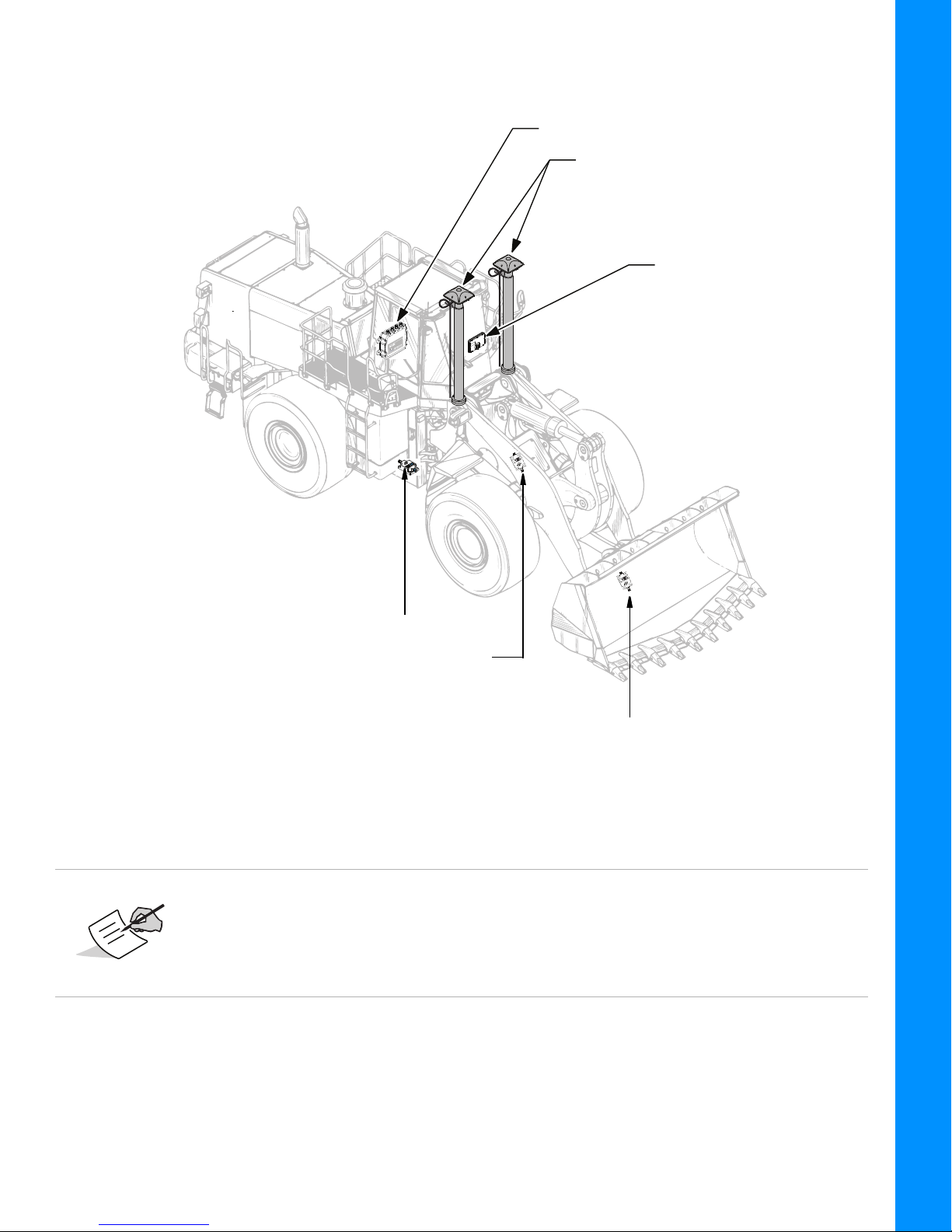
Introduction
MC-R3MC-i4 Controller/Receiver
GPS AntennasGPS Antenna (2)
GX-60 GX-55/GX-75
Control Box
Body Sensor
Boom Sensor
(Mounted Inside Boom)
Attachment/Bucket Sensor
(Mounted Inside Snap-on Well)
Figure 1-1: Wheel Loader System Components—Receiver, Antenna, Control Box and Sensors
The TS-i3 Boom Sensor is mounted on the inside of the Boom.
The TS-i3 Attachment/Bucket Sensor is mounted on the inside of the
Snap-on Well.
The TS-i3d Body Sensor is mounted on the body of the Wheel Loader.
System Components—Hardware and Software
P/N: 7010-1006
1-2
Page 10
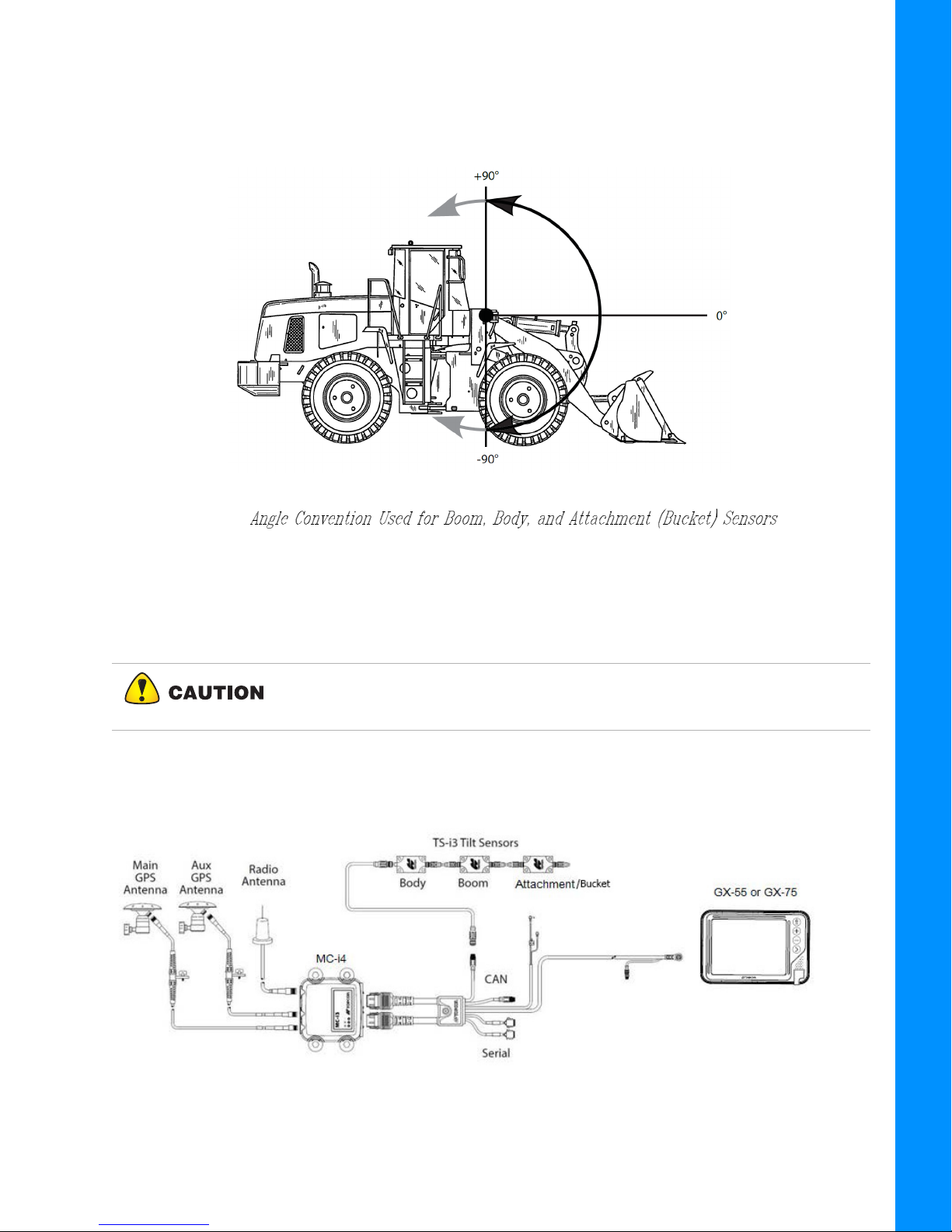
Sensor Angles
Sitting in the Cab facing forward, the Sensor Angles are 0° (straight ahead—horizontal),
+90° (straight up—vertical), and -90° straight down, see Figure 1-2.
Introduction
Figure 1-2:
Basic Cable Connections
Figure 1-3 shows the basic cabling connections for the Wheel Loader system. When installing
hardware components, use the Topcon supplied fuse or fused power from the Wheel Loader.
Connect the System ground to the frame side of the Ground Disconnect
Switch, do not connect the ground directly to the Wheel Loader’s Battery
Term in a l.
Figure 1-3: Basic Cable Connections for the Wheel Loader System
System Components—Hardware and Software
P/N: 7010-1006
1-3
Page 11
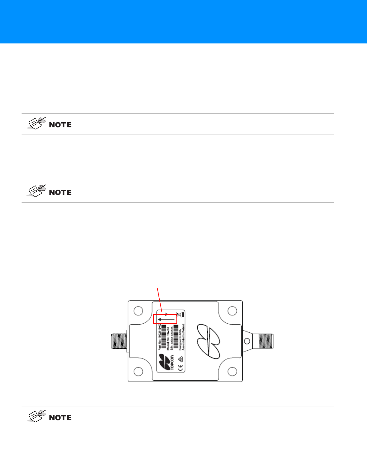
Installation
Orientation Arrow
Tilt Sensor Installation
This chapter describes installation of the TS-i3 sensors onto the body, boom, and attachment/bucket of
the wheel loader.
TS-i3 Sensors
When mounting the tilt sensors, begin with the Attachment/Bucket sensor to help
simplify cable routing.
Each TS-i3 sensor contains a single or dual axis sensor element, and each sensor will be different
depending on where they are mounted. Sensors mounted on the boom and attachment are single axis
type, and are only mounted in a left or right orientation. The sensor mounted on the body is a dual
axis type, and is mounted only with a flat orientation with the label up.
The Dual Axis TS-i3 sensor is labeled TS-i3d.
When installing the sensors, ensure that they are mounted parallel to the axis being measured (See
Figure 2-1 below). Locate surfaces that protect the sensor from physical damage and are convenient
for cable routing. When the position of the implement is at zero degrees (horizontal), make a note of
the direction of the arrow marker on the serial label (located on the top of the sensor). This direction
is needed during calibration. The calibration process uses 3D-MC to enter direction, orientation, and
other sensor variables.
TS-i3 Sensor Orientation
Figure 2-1: TS-i3 Sensor Orientation
Mount each tilt sensor within +/- 20° of the pivot centerline. Although this does not
ensure system performance, squaring the sensors to each part of the machine
makes for a cleaner looking installation.
Tilt Sensor Installation
P/N: 7010-1006
2-1
Page 12

Tilt sensor orientation is determined when the implement is horizontal (0°). The
orientation of each tilt sensor is entered in 3D-MC.
Install Boom and Attachment/Bucket sensors with their serial numbers in
ascending or descending order.
When entering sensor information, make note of each sensor's serial number and
its orientation. TS-i3 sensor orientation for Boom and Bucket (also known as the
Attachment sensor) is only left or right.
Attachment/Bucket Sensor Installation
Installation
CAN Termination
To ensure proper communication between the sensors and the Display box, the last
sensor physically connected must use the hard terminator provided with the Wheel
Loader systems. This hard terminator connects to the Bucket sensor
The Attachment/Bucket sensor is the most challenging sensor to correctly mount—and to keep the
sensor and cables safely protected from damage.
Fabrication of a sensor guard and cable protection is recommended to minimize
damage. Because this varies widely, such specific protection is not included in the
Topcon kit and must be supplied by the installer.
Attachment/Bucket Sensor Installation
P/N: 7010-1006
2-2
Page 13

Non Quick Release Attachment/Bucket Sensor
Mount TS-i3
Attachment/Bucket
Sensor Here
Bucket Snap-on Well
Installation
The recommended location for the TS-i3 Attachment/Bucket Sensor is on the inside of the
Bucket Snap-on Well.
Installation
Figure 2-2: Recommended Placement of TS-i3 Attachment/Bucket Sensor
Attachment/Bucket Sensor Installation
P/N: 7010-1006
2-3
Page 14

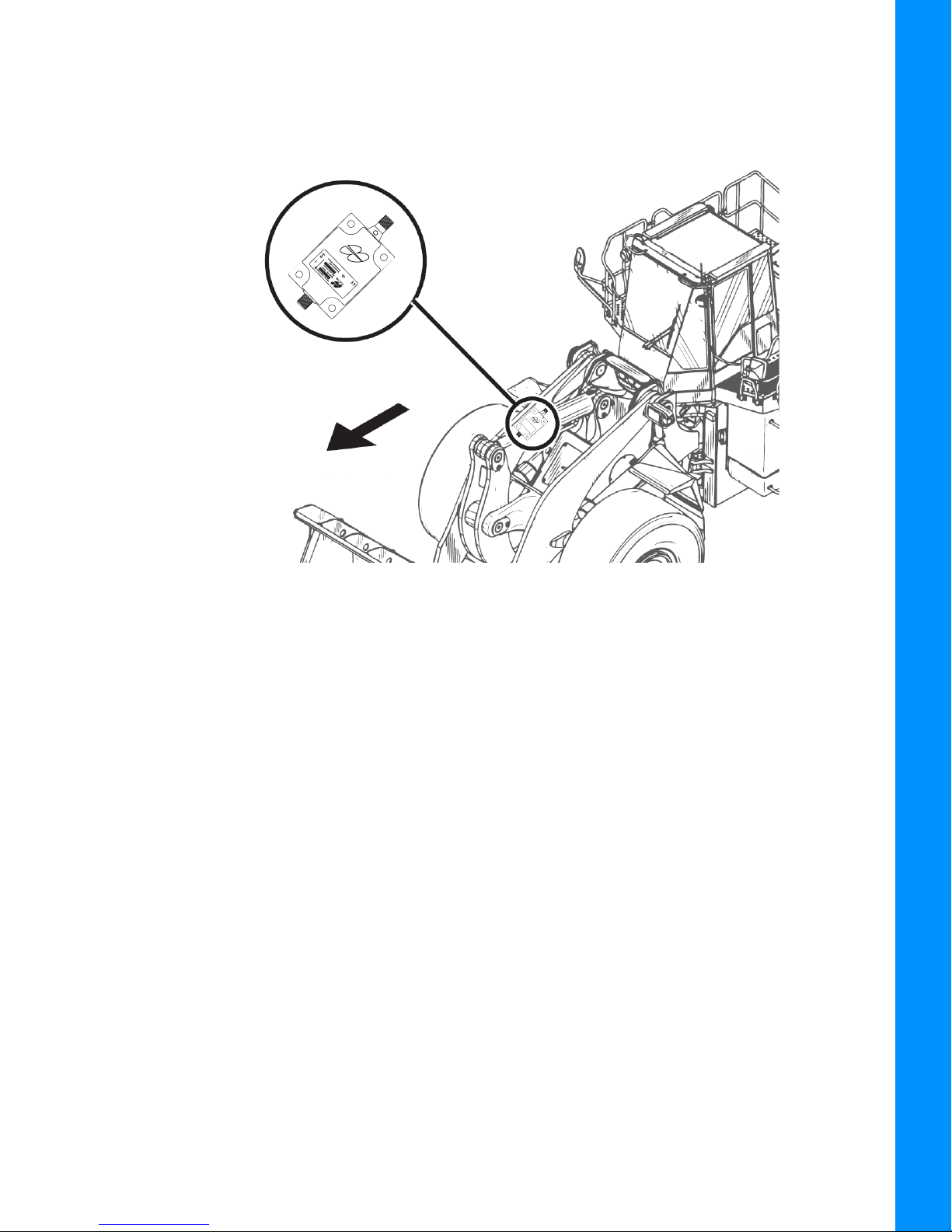
Quick Release Attachment/Bucket Sensor Installation
Direction of Travel
TS-i3
Attachment/Bucket
Sensor
When using a Quick Release Wheel Loader Bucket Assembly the recommended mounting location for
the TS-i3 sensor is as shown in Figure 2-3.
Installation
Figure 2-3: Mounting Location for TS-i3 Sensor—When Using a Quick Release Wheel Loader
Bucket Assembly
Attachment/Bucket Sensor Installation
P/N: 7010-1006
2-4
Page 15
Boom Sensor Installation
Direction of Travel
Weld or bolt the TS-i3 Boom sensor onto the inside of the Boom with the with the arrow facing
forward in the direction of travel.
Installation
Figure 2-4: Boom Sensor Location
Boom Sensor Installation
P/N: 7010-1006
2-5
Page 16

Body Sensor Installation
Direction of Travel
For this installation ensure that the Body sensor is a Dual Axis TS-i3d sensor.
Mount the Dual Axis TS-i3d sensor to the front frame of the Wheel Loader. Ensure that the sensor
is squared to the Wheel Loader. Weld or bolt the Body Sensor so that the sensor is flat.
Installation
Figure 2-5: Body Sensor Wheel Loader Installation
Body Sensor Installation
P/N: 7010-1006
2-6
Page 17

GNSS Antenna, Mount, and Mast Installation
Antenna Mast
Antenna
Mast Weld
Mount
1. Weld the Antenna Mast Weld Mount to top of the Front Lamp Protection plate (Figure 2-8).
Different Wheel Loaders may require fabrication of a unique mounting surface for the
Antenna Mask Mount. Ensure that the top of the antenna is flush or slightly above
the Cab roof when mounted.
2. Repeat Step 1 on the opposite side of the Wheel Loader.
Installation
Figure 2-6: Antenna Mast and Mast Weld Mount
3. Install the Antenna Mast.
4. Install the Strain Relief Bracket. Remove the two small Bolts and route the GNSS Antenna
Cable through the Strain Relief Bracket (Figure 2-7).
GNSS Antenna, Mount, and Mast Installation
P/N: 7010-1006
2-7
Page 18

.
Mast
Strain Relief Bracket
Cable
Loop
GNSS
Antenna Cable
Bolt (2)
Strain Relief Bracket
Installation
Ensure enough cable is routed through the bracket, so that the cable can be looped
over and threaded into the bracket if or when the antenna is removed from the Wheel
Loader (Figure 2-7).
GNSS Antenna
Figure 2-7: Installing the Strain Relief Bracket
5. Repeat steps 3 and 4 for the second antenna mast.
GNSS Antenna, Mount, and Mast Installation
P/N: 7010-1006
2-8
Page 19

6. Install the two GNSS antennae.
Antenna Mast Weld Mount (2)
Antenna Mast (2)
Antenna (2)
Front Lamp Protection
Plate
Installation
Figure 2-8: GNSS Antenna, Mast, Weld Mounts, and Front Lamp Protection Plate—Installed on
the Wheel Loader
GNSS Antenna, Mount, and Mast Installation
P/N: 7010-1006
2-9
Page 20

Machine Setup and Configuration
Entering Sensor Information
Topcon recommends starting with a new machine configuration file in order to reduce
potential machine configuration file issues.
Taking Machine Measurements
Before taking machine measurements, note the following:
• Check the TS-i3 sensor's serial numbers before installing. The last two digits of the serial number
determine the sensor CAN address, and must be unique to each machine.
– For example, sensor serial number 0302 and 0402 will have the same CAN Termination address
("02"), causing communication errors.
• A sensor’s serial number ending in 00 is considered a special CAN identifier, and will be
identified as 01 in 3D-MC software. Therefore, if you have a sensor with 00 and a sensor with
01, there will be some confusion in 3D-MC software.
• Accurately measure and enter the machine dimensions into the 3D-MC machine builder. Write
your measurements on the lines at the side of the following screen captures (Figure 3-1).
Incorrect measurements and/or data entry errors have a direct affect on excavating
accuracy. Measure twice and verify your data entry to ensure accuracy.
Entering Sensor Information
P/N: 7010-1006
3-1
Page 21

Record Wheel
Loader
Information
below:
Record Wheel
Loader
Information
below:
Machine Setup and Configuration
Figure 3-1: GNSS, GNSS Aux, Body and Boom Machine Measurements
Make a copy of this page. Use this page to record the GNSS Wheel Loader Antenna,
GNSS Aux Wheel Loader Antenna, Body, and Boom Loader information for your Wheel
Loader.
Taking Machine Measurements
P/N: 7010-1006
3-2
Page 22

Machine Setup and Configuration
Record Wheel
Loader
Information
below:
Figure 3-2: Bucket and Tilt Bucket Measurements
Make a copy of this page. Use this page to record Wheel Loader Bucket and Tilt
Bucket Setup information for your Wheel Loader.
Taking Machine Measurements
P/N: 7010-1006
3-3
Page 23

Entering Sensor Information
Power up the system and allow several minutes for the 3D-MC software to detect the sensors.
Before calibrating the sensors on the excavator systems, set up each sensor in the 3D-MC Software
Interface. You will need the following information:
• the last two digits of the sensor’s serial number
• the physical orientation of the sensor mounting
Step 1: Configure the Machine File and the Wheel Loader options.
1. In 3D-MC, tap Topcon Menu Button—Control Machine setup.
2. Select a current machine file and tap Edit, or tap New to create a new machine file.
3. On the Configuration name/type screen, enter or select the appropriate data as needed
(Figure 3-3).
Machine Setup and Configuration
Figure 3-3: Configuration Name and Type
4. Tap Next to navigate to the Wheel Loader Options screen (Figure 3-3).
5. Select MC-i3/MC-i4 as the Position Input (Figure 3-4).
Figure 3-4: Wheel Loader Options
Entering Sensor Information
P/N: 7010-1006
3-4
Page 24

6. Select MC-i3/MC-i4 for Sensor Input (Figure 3-4).
7. Tap Next to navigate to the Wheel Loader Antenna screen, and select/enter the appropriate
values as needed.
Figure 3-5: Wheel Loader Antenna
8. Tap Next to navigate to the Wheel Loader Antenna (Aux) screen, and select/enter the
appropriate values as needed (Figure 3-5).
Machine Setup and Configuration
Figure 3-6: Wheel Loader Antenna (Aux)
Entering Sensor Information
P/N: 7010-1006
3-5
Page 25

Step 2: Designate each sensor to its corresponding implement.
Body Sensor ID
Boom Sensor ID
Bucket Sensor ID
For the Body, Boom, and Attachment/Bucket sensors, tap the appropriate Sensor ID
box and select the serial number (last two digits) of the sensor corresponding to the
machine element. Refer to your notes from installation to select the correct sensor ID
from the drop-down menu.
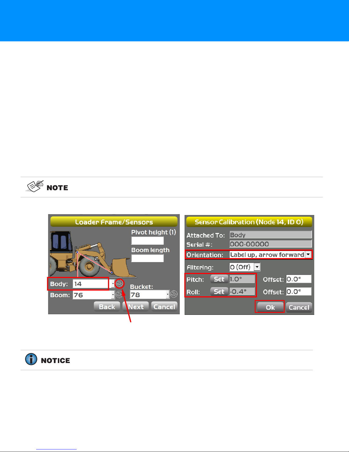
1. Tap Next to navigate to the Loader Frame/Sensor screen (Figure 3-7).
Machine Setup and Configuration
Figure 3-7: Wheel Loader Frame/Sensors
2. Tap the appropriate Body Sensor ID, Boom Sensor ID, or Bucket Sensor ID box and select
the serial number (last two digits) of the sensor corresponding to the machine element that you
are working on.
3. Enter the appropriate measurement values.
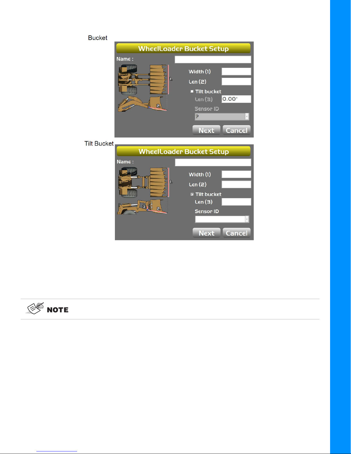
4. Tap Next on the Loader Frame/Sensors screen (Figure 3-7)—the WheelLoader Bucket
Setup screen appears (Figure 3-8)
Figure 3-8: Wheel Loader Bucket Setup
a. Enter or select the appropriate data as needed (Figure 3-8).
Entering Sensor Information
P/N: 7010-1006
3-6
Page 26
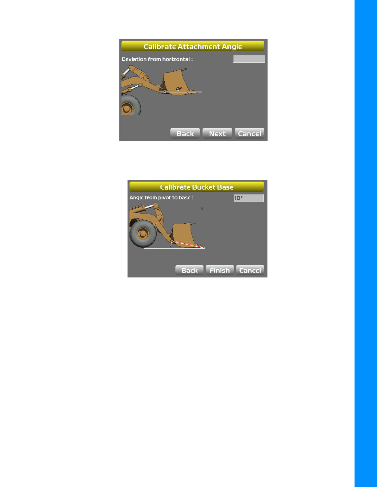
b. Press Next to access the Calibrate Attachment Angle screen (Figure 3-9).
Figure 3-9: Calibrate Attachment Angle
c. Press Next—the Calibrate Bucket Base screen populates (Figure 3-10).
Machine Setup and Configuration
Figure 3-10: Calibrate Bucket Base
d. Press Finish on the Calibrate Bucket Base screen—to return to the WheelLoader Bucket
Setup screen (Figure 3-11).
Entering Sensor Information
P/N: 7010-1006
3-7
Page 27
Machine Setup and Configuration
Figure 3-11: WheelLoader Bucket Setup
f. Repeat Steps 4a through 4d for each attachment.
Information regarding body, boom and attachment/bucket sensor calibration
routines are described in the next chapter.
Entering Sensor Information
P/N: 7010-1006
3-8
Page 28

Light Bars
1. Tap Next to access the Light Bars screen.
Figure 3-12: Light Bars
2. Enter the desired settings.
Machine Configuration Complete
Machine Setup and Configuration
Tap Next to access the Configuration complete! screen.
Figure 3-13: Configuration complete!
Light Bars
P/N: 7010-1006
3-9
Page 29
Calibration
Wrench Icon
Body Sensor Calibration
Once the sensors are named, assigned to a machine element, and the sensor orientation is selected,
calibrate each sensor using the 3D-MC Software Interface. Sensor calibrations can be performed at any
time.
1. Using the 3D-MC Software Interface, tap Topcon Menu Button > Control > Machine setup.
2. Select the appropriate machine file, and tap Edit.
3. Continue to press Next to access the Loader Frame/Sensors screen (Figure 4-1).
4. Tap the Wrench icon for the Body sensor (Figure 4-1).
5. Tap the Orientation box, and select the physical orientation of the mounted sensor then tap Ok
(Figure 4-1).
In Figure 4-1, Orientation is shown as Label up, with the arrow forward pointing to
one of the four directions.
Figure 4-1: Body Sensor Calibration Screens
Body Sensor Calibration requires both the Pitch and Roll calibrations. Perform
both calibrations at the same time to ensure accurate measurements.
Body Sensor Calibration
P/N: 7010-1006
4-1
Page 30

Calibration
Wheel Loader Starting—Position 1
Wheel Loader Rotated 180º—Position 2
Figure 4-2: Body Calibrations for Latitudinal Slope
6. Position the machine on a flat and stable surface—free of obstructions.
7. Tap Set next to Pitch, enter the value as zero, and tap Set again (Figure 4-1)—repeat this step
for setting the Roll value.
8. Mark the position on the four wheels on the ground.
9. Move the Wheel Loader around 180 degrees so that the tires are repositioned on the same
ground marks.
10. Tap Set next to Pitch, set the value to half the displayed values and tap Set again.
For example, (-5.3/ 2 = -2.65 and -2.8/ 2 = -1.4)—(Refer to Figure 4-1).
11. Tap Set next to Roll, set the value to half the displayed values and tap Set again.
12. Tap OK.
Body Sensor Calibration
P/N: 7010-1006
4-2
Page 31
Boom Sensor Calibration
Wrench Icon
When performing the Boom Sensor Calibration, a laser is recommended to
correctly position the Boom to zero degrees.
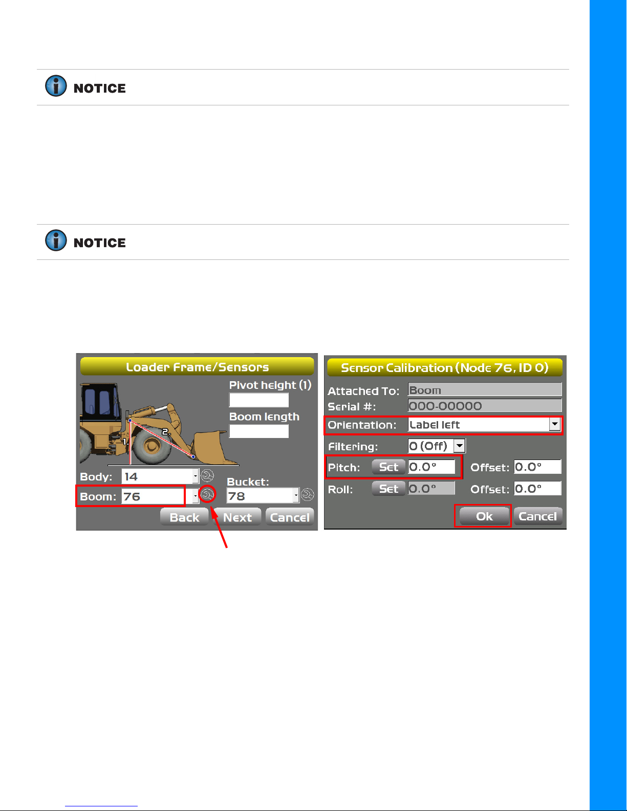
1. Tap the Wrench Icon that corresponds to the Boom sensor (Figure 4-3).
2. Select the correct Orientation from the drop-down menu.
3. Ensure the Wheel Loader is parked on a flat and stable surface.
4. Place a zero slope rotating laser along the side of the Wheel Loader.
The laser should shine on both the Boom and Bucket Pivots.
5. Adjust the laser height to strike the center of the Boom Pivot.
6. Move the Boom to align the Bucket Pivot with the laser.
Calibration
7. Tap t h e Wrench Icon that corresponds to the Boom sensor.
Figure 4-3: Boom Sensor Calibration Screens
8. Tap Set next to Pitch on the Sensor Calibration screen, enter the value as zero, and tap Set
again (Figure 4-3).
9. Tap Ok to return to the Loader Frame/Sensors screen.
Boom Sensor Calibration
P/N: 7010-1006
4-3
Page 32

Attachment/Bucket Sensor Calibration
Wrench Icon
1. Tap the Wrench Icon that corresponds to the Bucket sensor (Figure 4-4).
2. Select the correct Orientation from the drop down menu.
3. Ensure that the Wheel Loader is parked on a flat and stable surface.
4. Place a zero slope rotating laser along the side of the Wheel Loader.
The laser must shine on both the Bucket Pivot and the tip of the Bucket Cutting
Edge or the Bucket Teeth.
5. Adjust the laser height to strike the center of the Bucket Pivot.
6. Rotate the Bucket to align to the Bucket Cutting Edge or the Bucket Teeth with the laser.
Calibration
Figure 4-4: Bucket Sensor Calibration Screens
Attachment/Bucket Sensor Calibration
P/N: 7010-1006
4-4
Page 33

7. Tap t h e Wrench Icon that corresponds to the Boom sensor (Figure 4-5).
Wrench Icon
Figure 4-5: Resetting the Boom Sensor Pitch to Zero
8. Tap Set next to Pitch on the Sensor Calibration screen (Figure 4-5), enter the value as zero,
and tap Set again.
Calibration
9. Tap Ok to return to the Loader Frame/Sensors screen.
Attachment/Bucket Edge Sensor Calibration
Perform the following Attachment/Bucket Edge Calibration Sensor procedure for all
attachments.
1. In 3D-MC Software Interface application, tap Topcon Menu Button > Control > Machine
setup.
2. Tap Next until the WheelLoader Buckets screen appears (Figure 4-6).
3. Select the Name of the attachment that is on the WheelLoader Buckets screen.
4. Tap Edit on the WheelLoader Buckets screen. The WheelLoader Bucket Setup screen
appears (Figure 4-6).
Figure 4-6: WheelLoader Buckets and WheelLoader Buckets Setup
Attachment/Bucket Edge Sensor Calibration
P/N: 7010-1006
4-5
Page 34

5. Tap Next.
6. With the Bucket Pivot Point and the Bucket Teeth aligned at zero (0.0) degrees, tap Next
(Figure 4-7).
Figure 4-7: Calibrate Attachment Angle
7. Set the bottom of the Bucket flat on the ground and press Finish (Figure 4-8).
Calibration
Figure 4-8: Calibrate Bucket Base
Sensor Filtering
The filter level for each sensor can be changed depending on the application and the operator’s
choice. A value of 4 (heavy filtering) will dampen sensor reaction, while a value of 1 (light filtering)
will cause faster sensor reaction.
1. Using the 3D-MC Software Interface, tap Topcon Menu Button > Control > Machine
>Setup. Select the applicable machine file and tap Edit.
2. Tap Next to navigate to the Loader Frame/Sensors screen (Figure 4-9).
3. Tap the Wrench Icon next to the Sensor ID that you will be adjusting.
Sensor Filtering
P/N: 7010-1006
4-6
Page 35

4. Select a Filtering level and tap Ok (Figure 4-9).
Wrench Icon (3)
Figure 4-9: Sensor Filtering
5. Navigate through the remaining steps of Machine Setup, then save the file, and exit the 3D-MC
Software Interface.
Calibration
Sensor Filtering
P/N: 7010-1006
4-7
Page 36

Safety Warnings
It is your responsibility to be completely familiar with the cautions described in this manual. These
messages advise against the use of specific methods or procedures which can prevent personal injury,
damage to the equipment, or unsafe operating conditions. Remember, most accidents are caused by
failure to observe basic safety precautions.
General Precautions
1. Read and become familiar with the machine manufacturer’s operating instructions, including safety
information, before installing or using your Topcon equipment.
2. Use extreme caution on the job site. Working around heavy construction equipment can be
dangerous.
3. DO NOT attach system brackets or hose connections while the machine is running.
4. DO NOT allow any Wheel Loader system component to limit the visibility of the operator.
5. Use cable ties, supplied with the Wheel Loader system, to keep hoses and wires secured and away
from possible wear or pinch points.
6. Use eye protection whenever welding, cutting, or grinding is being done on the machine.
7. Protect yourself at all times, and wear protective clothing, when working on or near hydraulic lines.
Hydraulic lines can be under extreme pressure, even when the machine is turned off.
Relieve all pressure in the hydraulic lines before disconnecting or removing any lines,
fittings or related components. In case of injury, seek medical assistance
immediately.
8. Avoid direct exposure to your eyes when using laser control.
DO NOT stare into the laser beam or view the beam directly with optical
equipment.
9. Use appropriate welding precautions and practices when welding. After welding, all paint all
affected areas with a rust inhibitor
DO NOT weld near hydraulic lines or on any equipment when in operation.
Disconnect all Topcon system electrical cables prior to welding on the machine.
General Precautions
P/N: 7010-1006
5-1
Page 37

All mounting bracket welds must be secure and strong to prevent sensor
equipment from vibrating excessively or from becoming detached at the weld
during operation.
10. To prevent vandalism or theft, do not leave removable Topcon components on the machine at
night. Remove the components each evening and store appropriately in the carrying case.
11. Keep the carrying case dry at all times.
DO NOT allow moisture to get inside the case. Moisture trapped in the case can
adversely affect the components. If moisture does enter the carrying case, leave it
open and allow it to thoroughly dry before storing any components.
Radio Usage Information
All users must obtain an FCC (Federal Communications Commission) license before operating the
GPS+ system, GPS RTK (Real-Time Kinematic), or simultaneous calculation of Global Positioning
System and Global Navigation Satellite System.
Safety Warnings
• The Federal Communications Commission is at: http://www.fcc.gov/
• The rules are at: http://www.access.gpo.gov/nara/cfr/waisidx_00/47cfr90_00.html
There have been m a n y p roblems in the p a st with RTK base radio modems interfering with voice users.
The issue finally culminated with the FCC refusing to grant licenses until something was done to
ensure that surveyors did not interfere with voice users. The solution was to stop using frequencies
in the 469 MHz range, to add an identifier to the broadcast message, and other measures designed
to minimize interference with voice users. The user and his employer are subject to fines of up to
$82,500, confiscation of surveying equipment and legal action, if the rules are ignored.
Topcon cannot obtain the license for the user. There are companies to assist with licensing. Two are
listed here:
Professional Licensing Consultants Inc.
P. O. B ox 17 1 4
Rockville, MD 20849-1714
Atlas License Company and Data Services
1725-A North Shadeland Avenue
Indianapolis, IN 46219
http://www.alcds.com/
Radio Usage Information
P/N: 7010-1006
5-2
Page 38

Usage Warnings
If this product has been dropped, altered, transported or shipped without proper
packaging, or otherwise treated without care, erroneous measurements may occur.
The owner should periodically test this product to ensure it provides accurate
measurements. Inform TPS immediately if this product does not function properly.
Safety Warnings
Usage Warnings
P/N: 7010-1006
5-3
Page 39

Specifications subject to change without notice. All rights reserved. 7010-1006 Revision B, 8/2018 © 2018 Topcon Corporatiion
www.topconpositioning.com
 Loading...