

Page 1
COMBINATION
DOME CAMERA SYSTEMS
Combination Dome Cameras
For Outdoor Use For Indoor Use
For Outdoor Use For Indoor Use
C-BC711P
Ceiling Suspension
Bracket
C-BC711PM
Pole Mounting
Bracket
C-CC764
multi function type
C-CC714
standard type
Brackets and Cover
C-BC511C
Ceiling Mount
Cover
with Ceiling Mount
Cover C-BC511C
C-BC511P
Ceiling Suspension
Bracket
C-BC511U
Flush Ceiling
Mounting Bracket
C-CC564
multi function type
C-CC514
standard type
C-BC511A
Anchor Bracket
C-BC711W
Wall Mounting
Bracket
C-RM500
Remote Controller
C-A711DM
Smoked Dome
Cover
C-BC511C-S
Ceiling Mount
Cover (Smoked)
C-BC511W
Wall Mounting
Bracket
Controller and Units
C-AL80
Alarm Unit
C-BC511U-S
Flush Ceiling Mounting
Bracket (Smoked)
C-IF500
Interface Unit
Page 2
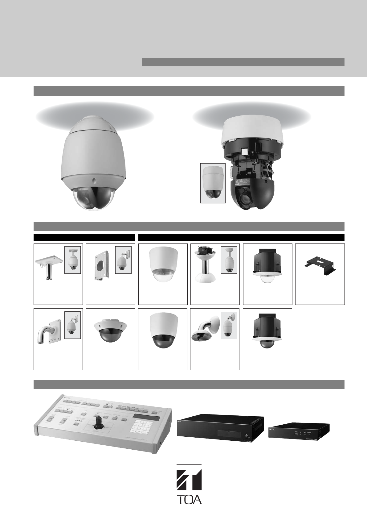
Combination Dome Cameras
Configuring a perfect surveillance system.
■
Higher resolution delivers better images.
TOA cameras now feature a higher horizontal resolution of
480 lines (NTSC) to deliver images of enhanced quality.
■
All points coverage at high speed.
TOA's new combination dome cameras help to improve
monitoring environments with an ideal coverage area that is
made possible with a 360°
rotation range to cover any
possible position. Capable of a
maximum rotating speed
(panning/tilting) of 360°/second,
these versatile cameras allow
rotation speed to be slowed down
as desired.
■
Expanded zooming ability.
TOA cameras are capably equipped for zooming as needed.
C-CC564 and C-CC764 incorporate a 23X ultra wide-angle
zoom lens for better coverage of a desired image. If even
more zooming is required, 12X digital zooming can be
activated, resulting in an extraordinary combined zoom factor
of up to an 276X*.
*C-CC564 and C-CC764 cameras are equipped with a high-speed,
wide-angle lens having a 23X zoom while C-CC514 and C-CC714
cameras are equipped with a high-speed, wide-angle lens having a
22X zoom. With the 12X digital zoom activated, a total 276X zoom is
possible for C-CC564 and C-CC764 cameras and 264X zoom for
C-CC514 and C-CC714 cameras.
■
Intelligent image optimizing using the Wide
360˚
Dynamic Range function.*
If the area of coverage exhibits varying brightness levels, it
causes various problems that prevent achieving superb
image quality. These problems pose severe difficulties for
cameras that utilize conventional technology for dealing with
brightness variations. The following two examples illustrate
the problem.
Placing the focus on
the outdoors results
in the indoors being
too dark to see well.
(Photo A)
However, setting the
focus on the indoors
now "whites out" the
outdoor area.
(Photo B)
■
Sophisticated autofocus modes add
versatility.
TOA cameras are equipped with advanced auto-focusing.
Three independent modes are offered: Auto focus for normal
operation is activated with a single push. Stop Auto Focus
activates if the camera view or viewing angle changes. To
keep auto focus working continuously, the Continuous auto
focus can be engaged.
■
Motion detection function initiates
operation.*
Incorporated into the C-CC564 and C-CC764 are a motion
detection function. When a moving object enters a camera's field
of view, the camera will initiate a preprogrammed operation or a
series of operations. The camera's
view can be monitored onscreen
with a window that is divided into
64 segments and from these,
eight 8 areas can be selected
as motion detection zones.
■
Image clarity maintained for day and night
with sensitivity boost.
In night or dark lighting conditions, the camera's shutter
speed is automatically reduced so that more light can enter.
This function effectively increases the camera's sensitivity so
that dark areas can be made up to 32 times brighter.
■
B/W mode improves low light performance.*
Combination dome cameras also incorporate a separate B/W
mode. At night, as light intensity decreases, this mode
automatically activates, boosting camera sensitivity and
making it possible to capture clear images even in
unsatisfactory light conditions. When light conditions are
satisfactory, the camera will revert to its primary function as a
color camera. Used together, the sensitivity boost and B/W
modes allow TOA combination dome cameras to efficiently
function for 24-hour monitoring.
Note: B/W mode allows monitoring target areas that are not possible
in normal light conditions.
TOA Combination Dome Cameras
incorporate a special Digital Signal
Processor (DSP) that works to optimize
image, producing a single image of
exceptional clarity that is comparable to
the same image when viewed with
human eyes.
Sensitivity boost allows
cameras to provide good
color image quality for
dark areas.
B/W mode.
(color image)
(B/W image)
Page 3
■
Protecting user privacy.
a) Privacy Masking function.*
Depending on system use requirements, there may be
several areas that the system administrator decides does not
require surveillance for whatever reason. Users are allowed
to select in advance the locations they wish to be excluded
from surveillance in a camera's field of view.
Onscreen selected areas can be masked with a rectangle
and a maximum of 8 areas (a single screen can have 2
masked areas) can be masked for privacy.
b) Restricting camera movement.
In addition to masking areas for privacy, a hardware-oriented
method is also available. A camera's rotation range in both
horizontal and vertical directions can be restricted to exclude
areas from surveillance.
■
Outdoor installation ready.
(meets IP66 standards)
C-CC714 and C-CC764 utilize a waterproof and dustproof
design that fully conforms to IP66 standards and can be safely
installed outdoors. Cameras are cased in a special housing that
withstands outdoor conditions, allowing them to be installed
outdoors, even if the location is directly exposed to rain.
■
Withstands cold weather conditions.
C-CC714 and C-CC764 incorporate a heating circuit that allows
operation in severe temperatures down to –40°C. Heating is
automatically turned on when ambient temperatures go below
0°C and will automatically switch off when the temperatures rise.
Note: Turning the camera on if the camera interior is below 0°C may
not result in producing an immediately viewable image. Once the
camera interior temperature rises above 0°C, images will be viewable.
■
Route tracing facilitates subject monitoring.
In order to make it easy to follow a subject
along a route, the camera can be set to
automatically monitor preset points for
up to 60 seconds. Two different routes
can be programmed.
■
Configuring programmable tours.
Through combinations of the 255 preset positions and trace
function, a camera can be programmed to automatically and
continuously repeat a travel pattern as a tour. Up to 16 tour
patterns can be programmed. Any tour program is able to
have a different travel pattern that can be activated by an
alarm input or timer.
FEATURES
■
Programmable camera operation initiated
by alarm input.
A useful Alarm function allows programming camera operation
that can be activated by an alarm input.
Desired camera operations such as position replay, touring,
tracing, and control of the auxiliary terminal can be programmed
to activate when the camera receives an alarm input. Each
camera is equipped with three (C-CC564 has eight) alarm inputs
and each alarm input can be set to respond with different
preprogrammed operation.
■
Preset operation start with Timer program
function.
A camera can conveniently be set to begin operation at a
preset time with an builtin timer. Each camera has a clock
function that can be set to initiate operation at a preset time.
The timer can be set for a specific date, day of the week, or
daily. Up to 16 different timer programs can be set.
■
Software for maintenance.
TOA cameras include dedicated software that allows easy
titles to be set and to create a backup of parameters with
a PC.
■
Flexible installation options.
TOA cameras can easily be installed on ceilings, walls or on
poles thanks to the wide range of mounting brackets available.
■
Titling options.
To facilitate camera use, various titles can be input and displayed
on the monitor. In addition to camera and position titles, other
titles for display include trace title, displayed while the trace
function is on, tour title, displayed when tour function is activated,
and alarm title displayed when an alarm input is received.
■
Other functions.
• Tilt (vertical) range: +5° — –185°.*
•Auto flip function*
• Rotation speed can be varied to match lens zooming ratio
in manual operation mode.
• Freeze preset function*
Displays the still image during camera movement between preset positions.
• Flicker-free operation
• The camera is equipped with 3 (C-CC564 has 8) alarm
inputs and 1 auxiliary contact output.
• RS-485 protocol control.
Function Comparison Chart
Minimum Illumination 1 lx (50 IRE) 3 lx (50 IRE) 1 lx (50 IRE) 3 lx (50 IRE)
(High-Sensitivity: OFF)
Wide Dynaic Function — ● — ●
B/W Mode Function — ● — ●
Optical Zooming 22x 23x 22x 23x
Zoom Speed
(WIDE end to TELE end)
(preset operation) Approx. 1.3s Approx. 1.6s Approx. 1.3s Approx. 1.5s
(manual operation) Approx. 2.4s Approx. 2.9s Approx. 2.4s Approx. 2.9s
Rotating Range
Operating Temperature –10˚C to +50˚C –40˚C to +50˚C
Dust/Water Capability —— IP66
Auto Flip Function — ● — ●
Freeze Preset Function — ● — ●
Privacy Mask Function
Motion Detection Function
(Tilting)
C-CC514 C-CC564 C-CC714 C-CC764
0.3 lx (20 IRE) 1 lx (20 IRE) 0.3 lx (20 IRE) 1 lx (20 IRE)
+5° to – 95° +5° to – 185° +5° to – 90° +5° to –185°
—
— ● — ●
Up to 8
(up to 2 each frame) (up to 2 each frame)
—
Up to 8
*C-CC764 and C-CC564 only
Page 4
C-CC764/C-CC-714
COMBINATION DOME CAMERA (OUTDOOR USE)
C-CC764
FEATURES
• 255 preset positions
• 276X zoom (optical 23X, electronic 12X)
• Tilt rotation range +5° – -185°
(using Auto-Flip function)
•Pan rotation range continuous 360°
• Pan/tilt maximum rotating speed is 360°/sec
• 1/4 type CCD image device
• 480 lines high resolution
• Wide dynamic range
•Autofocus
• High-sensitivity function
(color and B/W modes)
• Preset sequency function
• Privacy masking function
• Restricting camera movement
•Auto-trace function
•Auto-tour function
• Motion detection function
•Auto-pan function
• Preset image freeze function
• Dust/Water Protection: IP66
• RS-485 protocol compatible
C-CC764
Power source 24V AC 50/60Hz (2P loose end)
Power consumption 10W (normal operation), 80W max.
Control RS-485 communications system (new protocol compatible)
Video Output VBS 1.0V(p-p), 75Ω, BNC-R jack
Camera Control Terminal RS-485 camera control connector, multi-pair cable 8P, loose end (3P of 8P)
Alarm Input 3 channels, no-voltage make contact input, open voltage: 18V DC,
Auxiliary Contact Output 1 channel, open collector output, withstand voltage: 30V DC,
Synchronization Internal synchronization/power synchronization
ID 8 characters (alphanumeric and symbols)
No. of Preset Positions 255 Positions
Automatic Operation Auto-pan, Preset sequence, Auto-trace (2 preset patterns (60s)), Tour (16 preset patterns)
Timer Refresh: Starts at the preset time every day or every week by timer settings
Camera
Image device 1/4 type CCD
Resolution Horizontal: 480 lines (at center)
S/N ratio 50dB
Minimum Illumination High-sensitivity function 0FF: 3 lx (50 IRE), 1 lx (20 IRE)
Backlight Compensation WIDE DYNAMIC/Pattern 1/Pattern 2/Pattern 3/OFF
Dynamic Range 46dB (backlight compensation: WIDE DYNAMIC operation)
High-Sensitivity Function B/W mode and slow shutter mode (32 times max.)
White Balance ATW/ AWB
Flicker Reduction Automatic correction
Electronic Zooming 12x zooming
Auto-Focus One push/stop AF/continuous
Lens
Zooming 23x
Effective Focal Length f = 3.6 – 82.8mm (23X)
Effective Angle of View Horizontal: 54° (W) – 2.5° (T), Vertical: 41.6° (W) – 1.9° (T)
Maximum Aperture F 1.6 (W) – F 3.7 (T)
Zoom Speed WIDE end to TELE end
Pan/Tilt Head
Rotating Range Panning: Endless 360° rotation, Tilting: +5° to –185°
Rotating Speed Panning/Tilting: 360°/s max. (preset operation), 360°/s max. (manual operation)
Other Function Auto-Pan, Freeze Preset, Manual Limit, Privacy Masking (up to 8),
Operating Temperature –40˚C to +50˚C
Operating Humidity Under 90% RH (no due condensation produced)
Application Indoors and outdoors (except seaside, industrial districts and locations exposed to fine particles,
Dust/Water Protection IP66
Finish Case, top cover and decorative frame: PC resin, light gray
Dimensions Camera section external diameter: ø230
Weight 3.9kg
Accessory
Option Wall mounting bracket: C-BC711W, Suspension bracket: C-BC711P,
SPECIFICATIONS
short-circuit current; Under 2mA (settable alarm action),
multi-pair cable 8P, loose end (3P of 8P)
permissible current: Under 100mA, multi-pair cable 8P, loose end (1P of 8P)
(phase adjustable when in power synchronization mode)
Camera, Position, Trace, Auto-pan, Tour, Home, Alarm, Sector, AUX
Program: Settable 16 actions
High-sensitivity function 0N: 0.03 lx (50 IRE), 0.01 lx (20 IRE)
Approx. 1.5s (preset operation), Approx. 2.9s (manual operation)
Motion Detect (each 8 presets at each 4 positions)
where the unit is subject to corrosion, and heights that expose the unit to strong wind pressure)
Sunshade: Aluminum, light gray, paint
Dome cover: PC resin (transparent)
Dome external diameter: ø 150mm
Top cover mounting screw (Hexagon socket screw M4 × 8) × 3,
CD-R (Camera controller software, manual (PDF)) × 1
Pole mounting bracket: C-BC711PM, Smoked dome cover: C-A 711DM
×
330.5 (H)mm
C-CC714
FEATURES
• 255 preset positions
• 264X zoom (optical 22X, electronic 12X)
• Tilt rotation range +5° – 90°
•Pan rotation range continuous 360°
• Pan/tilt maximum rotating speed is 360°/sec
• 1/4 type CCD image device
• 480 lines high resolution
•Autofocus
• High-sensitivity function
(color mode)
• Preset sequency function
• Restricting camera movement
•Auto-trace function
•Auto-tour function
•Auto-pan function
• Dust/Water Protection: IP66
• RS-485 protocol compatible
C-CC714
Power source 24V AC 50/60Hz (2P loose end)
Power consumption 10W (normal operation), 80W max.
Control RS-485 communications system (new protocol compatible)
Video Output VBS 1.0V(p-p), 75Ω, BNC-R jack
Camera Control Terminal RS-485 camera control connector, multi-pair cable 8P, loose end (3P of 8P)
Alarm Input 3 channels, no-voltage make contact input, open voltage: 18V DC,
Auxiliary Contact Output 1 channel, open collector output, withstand voltage: 30V DC,
Synchronization Internal synchronization/power synchronization
ID 8 characters (alphanumeric and symbols)
No. of Preset Positions 255 Positions
Automatic Operation Auto-pan, Preset sequence, Auto-trace (2 preset patterns (60s)), Tour (16 preset patterns)
Timer Refresh: Starts at the preset time every day or every week by timer settings
Camera
Image device 1/4 type CCD
Resolution Horizontal: 480 lines (at center)
S/N ratio 50dB
Minimum Illumination High-sensitivity function 0FF: 1 lx (50 IRE), 0.3 lx (20 IRE)
Backlight Compensation Pattern 1/Pattern 2/Pattern 3/OFF
High-Sensitivity Function Slow shutter mode (32 times max.)
White Balance ATW/ AWB
Flicker Reduction Automatic correction
Electronic Zooming 12x zooming
Auto-Focus One push/stop AF/continuous
Lens
Zooming 22x
Effective Focal Length f = 4.0 – 88mm (22X)
Effective Angle of View Horizontal: 47.3° (W) – 2.2° (T), Vertical: 36.5° (W) – 1.7° (T)
Maximum Aperture F 1.6 (W) – F 3.8 (T)
Zoom Speed WIDE end to TELE end
Pan/Tilt Head
Rotating Range Panning: Endless 360° rotation, Tilting: +5° to –90°
Rotating Speed Panning/Tilting: 360°/s max. (preset operation), 360°/s max. (manual operation)
Other Function Manual Limit
Operating Temperature –40˚C to +50˚C
Operating Humidity Under 90% RH (no due condensation produced)
Application Indoors and outdoors (except seaside, industrial districts and locations exposed to fine particles,
Dust/Water Protection IP66
Finish Case, top cover and decorative frame: PC resin, light gray
Dimensions Camera section external diameter: ø230
Weight 3.9kg
Accessory
Option Wall mounting bracket: C-BC711W, Suspension bracket: C-BC711P,
SPECIFICATIONS
short-circuit current; Under 2mA (settable alarm action),
multi-pair cable 8P, loose end (3P of 8P)
permissible current: Under 100mA, multi-pair cable 8P, loose end (1P of 8P)
(phase adjustable when in power synchronization mode)
Camera, Position, Trace, Auto-pan, Tour, Home, Alarm, Sector, AUX
Program: Settable 16 actions
High-sensitivity function 0N: 0.03 lx (50 IRE), 0.01 lx (20 IRE)
Approx. 1.3s (preset operation), Approx. 2.4s (manual operation)
where the unit is subject to corrosion, and heights that expose the unit to strong wind pressure)
Sunshade: Aluminum, light gray, paint
Dome cover: PC resin (transparent)
Dome external diameter: ø 150mm
Top cover mounting screw (Hexagon socket screw M4 × 8) × 3,
CD-R (Camera controller software, manual (PDF)) × 1
Pole mounting bracket: C-BC711PM, Smoked dome cover: C-A 711DM
×
330.5 (H)mm
Page 5

C-CC564/C-CC514
COMBINATION DOME CAMERA (INDOOR USE)
C-CC564
FEATURES
• 255 preset positions
• 276X zoom (optical 23X, electronic 12X)
• Tilt rotation range +5° – -185°
(using Auto-Flip function)
•Pan rotation range continuous 360°
• Pan/tilt maximum rotating speed is 360°/sec
• 1/4 type CCD image device
• 480 lines high resolution
• Wide dynamic range
•Autofocus
• High-sensitivity function
(color and B/W modes)
• Preset sequency function
• Privacy masking function
• Restricting camera movement
•Auto-trace function
•Auto-tour function
• Motion detection function
•Auto-pan function
• Preset image freeze function
• RS-485 protocol compatible
C-CC564
Power source 24V AC 50/60Hz
Power consumption 9W (normal operation), 19W max. (1.3A max.)
Control RS-485 communications system (new protocol compatible)
Video Output VBS 1.0V(p-p), 75Ω, BNC-R jack
Camera Control Terminal RS-485 camera control connector
Alarm Input 8 channels, no-voltage make contact input, open voltage: 18V DC,
Auxiliary Contact Output 2 channels, open collector output, withstand voltage: 30V DC,
Synchronization Internal synchronization/Power synchronization
ID 8 characters (alphanumeric and symbols)
No. of Preset Positions 255 Positions
Automatic Operation Auto-pan, Preset sequence, Auto-trace (2 preset patterns (60s)), Tour (16 preset patterns)
Timer Refresh: Starts at the preset time every day or every week by timer settings
Camera
Image device 1/4 type CCD
Resolution Horizontal: 480 lines (at center)
S/N ratio 50dB
Minimum Illumination High-sensitivity function 0FF: 3 lx (50 IRE), 1 lx (20 IRE)
Backlight Compensation WIDE DYNAMIC/Pattern 1/Pattern 2/Pattern 3/OFF
Dynamic Range 46dB (backlight compensation: WIDE DYNAMIC operation)
High-Sensitivity Function B/W mode and slow shutter mode (32 times max.)
White Balance ATW/ AWB
Flicker Reduction Automatic correction
Electronic Zooming 12x zooming
Auto-Focus One push/stop AF/continuous
Lens
Zooming 23x
Effective Focal Length f = 3.6 – 82.8mm (23X)
Effective Angle of View Horizontal: 54° (W) – 2.5° (T), Vertical: 41.6° (W) – 1.9° (T)
Maximum Aperture F 1.6 (W) – F 3.7 (T)
Zoom Speed WIDE end to TELE end
Pan/Tilt Head
Rotating Range Panning: Endless 360° rotation, Tilting: +5° to –185°
Rotating Speed Panning/Tilting: 360°/s max. (preset operation), 360°/s max. (manual operation)
Other Function Auto-Pan, Freeze Preset, Manual Limit, Privacy Masking (up to 8),
Operating Temperature –10˚C to +50˚C (continuously active for operation at temperature below 0°C)
Operating Humidity Under 90% RH (no due condensation produced)
Application Indoor used
Finish Base: PC/ABS resin, cool gray
Dimensions ø168
Weight 1.7kg
Accessory
Option Ceiling mount cover: C-BC511C, C-BC511C-S
SPECIFICATIONS
short-circuit current; Under 2mA (settable alarm action)
permissible current: Under 100mA,
relay contact output, permissible voltage: 110V DC, 125V AC,
permissible current: Under 1A
(phase adjustable when in power synchronization mode)
Camera, Position, Trace, Auto-pan, Tour, Home, Alarm, Sector, AUX
Program: Settable 16 actions
High-sensitivity function 0N: 0.03 lx (50 IRE), 0.01 lx (20 IRE)
Approx. 1.5s (preset operation), Approx. 2.9s (manual operation)
Motion Detect (each 8 presets at each 4 positions)
Camera: PC/ABS resin, black
×
234 (H)mm
Camera mounting screw × 4, Safety wire × 1,
CD-R (Camera controller software, manual (PDF)) × 1
Flush ceiling mounting bracket: C-BC511U, C-BC511U-S
Ceiling suspension bracket: C-BC511P
Wall mounting bracket: C-BC511W
Anchor bracket: C-BC511A
C-CC514
FEATURES
• 255 preset positions
• 264X zoom (optical 22X, electronic 12X)
• Tilt rotation range +5° – 90°
•Pan rotation range continuous 360°
• Pan/tilt maximum rotating speed is 360°/sec
• 1/4 type CCD image device
• 480 lines high resolution
•Autofocus
• High-sensitivity function
(color mode)
• Preset sequency function
• Restricting camera movement
•Auto-trace function
•Auto-tour function
•Auto-pan function
• RS-485 protocol compatible
C-CC514
Power source 24V AC 50/60Hz
Power consumption 9W (normal operation), 19W max. (1.3A max.).
Control RS-485 communications system (new protocol compatible)
Video Output VBS 1.0V(p-p), 75Ω, BNC-R jack
Camera Control Terminal RS-485 camera control connector
Alarm Input 3 channels, no-voltage make contact input, open voltage: 18V DC,
Auxiliary Contact Output 1 channel, open collector output, withstand voltage: 30V DC,
Synchronization Internal synchronization/power synchronization
ID 8 characters (alphanumeric and symbols)
No. of Preset Positions 255 Positions
Automatic Operation Auto-pan, Preset sequence, Auto-trace (2 preset patterns (60s)), Tour (16 preset patterns)
Timer Refresh: Starts at the preset time every day or every week by timer settings
Camera
Image device 1/4 type CCD
Resolution Horizontal: 480 lines (at center)
S/N ratio 50dB
Minimum Illumination High-sensitivity function 0FF: 1 lx (50 IRE), 0.3 lx (20 IRE)
Backlight Compensation Pattern 1/Pattern 2/Pattern 3/OFF
High-Sensitivity Function Slow shutter mode (32 times max.)
White Balance ATW/ AWB
Flicker Reduction Automatic correction
Electronic Zooming 12x zooming
Auto-Focus One push/stop AF/continuous
Lens
Zooming 22x
Effective Focal Length f = 4.0 – 88mm (22X)
Effective Angle of View Horizontal: 47.3° (W) – 2.2° (T), Vertical: 36.5° (W) – 1.7° (T)
Maximum Aperture F 1.6 (W) – F 3.8 (T)
Zoom Speed WIDE end to TELE end
Pan/Tilt Head
Rotating Range Panning: Endless 360° rotation, Tilting: +5° to –90°
Rotating Speed Panning/Tilting: 360°/s max. (preset operation), 360°/s max. (manual operation)
Other Function Manual Limit
Operating Temperature –10˚C to +50˚C (continuously active for operation at temperature below 0°C)
Operating Humidity Under 90% RH (no due condensation produced)
Application Indoor used
Finish Base: PC/ABS resin, cool gray
Dimensions ø168
Weight 1.7kg
Accessory
Option Ceiling mount cover: C-BC511C, C-BC511C-S
SPECIFICATIONS
short-circuit current; Under 2mA (settable alarm action)
permissible current: Under 100mA
(phase adjustable when in power synchronization mode)
Camera, Position, Trace, Auto-pan, Tour, Home, Alarm, Sector, AUX
Program: Settable 16 actions
High-sensitivity function 0N: 0.03 lx (50 IRE), 0.01 lx (20 IRE)
Approx. 1.3s (preset operation), Approx. 2.4s (manual operation)
Camera: PC/ABS resin, black
×
234 (H)mm
Camera mounting screw × 4, Safety wire × 1,
CD-R (Camera controller software, manual (PDF)) × 1
Flush ceiling mounting bracket: C-BC511U, C-BC511U-S
Ceiling suspension bracket: C-BC511P
Wall mounting bracket: C-BC511W
Anchor bracket: C-BC511A
Page 6

Brackets and Dome Cover for C-CC764/C-CC-714 (Outdoor Use)
C-BC711P
Suspension Bracket
The C-BC711P is exclusively designed to be
used to suspend TOA's outdoor
combination camera from a ceiling or eaves.
Finish Base: Aluminum, light gray, paint
Pipe: Stainless steel (SUS304)
Dimensions 140 (W) × 164 (H) × 200 (D)mm
Weight 1kg
Accessory Camera mounting screw (M5×12, with washer) × 3
Note: pay attention to the strength of the attaching portion.
C-BC711PM
Pole Mounting Bracket
Using the optional YS-60B and C-BC711W, the
C-BC711PM can mount the outdoor combination
camera on a pole.
Finish Stainless steel (SUS304)
Dimensions 140 (W) × 200 (H) × 60 (D)mm
Weight 700g
Note: Reinforce the pole mounting bracket and mounting band separately for security when
installing the camera in locations exposed to vibration or strong winds.
Maintenance the unit, mounting bracket and mounting band periodically to ensure that there
are no loose joint nor rickety parts.
C-BC711W
Wall Mounting Bracket
The C-BC711W is designed to be used to
mount TOA's outdoor combination camera
on a wall.
Finish Base: Aluminum, light gray, paint
Pipe: Stainless steel (SUS304)
Dimensions 140 (W) × 240 (H) × 188.1 (D)mm
Weight 1.3kg
Accessory Camera mounting screw (M5×12, with washer) × 3
Note: pay attention to the strength of wall surface.
The C-A711DM Smoked Dome Cover is specially designed to
be used in conjunction with TOA's Combination Cameras.
The Dome Cover is used to make it difficult for individuals to
see the camera's orientation.
Transmissivity Approx. 30%*
Finish Dome: PC resin, smoked
Frame: PC resin, light gray
Dimensions ø219.8 × 128 (H)mm
Weight 400g
*As a general guideline, the minimum object illumination of the camera equipped with the
Smoked Dome Cover is approximately 3.3 times that of the camera without the cover.
Note: Be careful when installing the camera with this cover in low illumination location as the
cover may cause camera sensitivity to decrease.
C-A711DM
Smoked Dome Cover
(Dome external diameter: ø150mm)
Brackets and Dome Cover for C-CC564/C-CC-514 (Indoor Use)
C-BC511A
Anchor Bracket
The C-BC511A is specially designed to
on the wall. The bracket facilitates mounting of the camera on the
plasterboard in the double ceiling or other locations where the
mounting screws cannot be installed securely.
Finish Surface-treated steel plate, black, paint
Dimensions 132 (W) × 30 (H) × 70 (D)mm
Weight 1.1kg
Accessory
mount TOA's Combination Cameras directly
Camera mounting screw × 4, Safety wire × 1, Paper pattern × 1
C-BC511P
Ceiling Suspension Bracket
The C-BC511P is a Ceiling Suspension Bracket
designed solely for suspending TOA's
Combination Cameras from the ceiling.
Finish Top cover: PC/ABS resin, cool gray
Pipe: Stainless steel (SUS304)
Bracket: Surface-treated steel plate, black, paint
Dimensions ø150 × 233mm
Weight 1.2kg
Accessory Top cover × 4, Safety wire × 1, Pattern paper × 1
C-BC511W
Wall Mounting Bracket
The C-BC511W Wall Mounting
Bracket is specially designed to mount
TOA's Combination Cameras to wall
surfaces. Install the unit only in a location
that can structurally support weight of the
unit and camera.
Finish Top cover: PC/ABS resin, cool gray
Pipe: Stainless steel (SUS304)
Bracket: Surface-treated steel plate, black, paint
Dimensions 150 (W) × 203 (H) × 203 (D)mm
Weight 1.1kg
Accessory Top cover × 4, Safety wire × 1, Paper pattern × 1
C-BC511C
Ceiling Mount Cover
The C-BC511C is a camera installation cover
designed solely for mounting TOA's
Combination Cameras. The cover is used when
ceiling or wall or suspending it from the ceiling. The cover is used
to make it difficult for individuals to see the camera's orientation.
Finish Case: PC/ABS resin, cool gray
Dimensions ø168 × 182.2 (H)mm
Weight 220g
mounting the Combination camera directly to a
Dome cover: Acrylic resin, transparent
(Dome external diameter: ø125mm)
C-BC511U
Flush Ceiling Mounting
Bracket
The C-BC511U bracket is designed to be
exclusively used for flush ceiling mounting
of TOA's combination camera. Use this bracket
where the fixing screws cannot be securely installed, such as on
the plaster panel of the dual-construction ceiling. Also, use this
bracket to minimize the exposure of the camera.
Finish Bezel: PC/ABS resin, cool gray
Dome cover: Acrylic resin, transparent
Bracket: Aluminum, black, paint
Surface-treated steel plate, black, paint
Dimensions ø250 × 282.7 (D)mm
Weight 1.2kg
Accessory Safety wire × 1, Paper pattern × 1
when mounting the camera to the ceiling surface
(Dome external diameter: ø125mm)
C-BC511C-S
Ceiling Mount Cover (Smoked)
The C-BC511C-S is a camera installation
cover designed solely for mounting TOA's
Combination Cameras. The cover is used when
ceiling or wall or suspending it from the ceiling. The cover is used
to make it difficult for individuals to see the camera's orientation.
Transmissivity Approx. 20%*
Finish Case: PC/ABS resin, cool gray
Dimensions ø168 × 182.2 (H)mm
Weight 220g
*As a general guideline, the minimum object illumination of the camera equipped with the
Ceiling Mount Cover is approximately 5 times that of the camera without the cover.
Note: Be careful when installing the camera with this cover in low illumination location as the
mounting the Combination camera directly to a
Dome cover: Acrylic resin, smoked
(Dome external diameter: ø125mm)
cover may cause camera sensitivity to decrease.
C-BC511U-S
Flush Ceiling Mounting
Bracket (Smoked)
The C-BC511U-S bracket is designed to
be exclusively used for flush ceiling
mounting of TOA's combination camera.
the ceiling surface where the fixing screws cannot be securely
installed, such as on the plaster panel of the dual-construction
ceiling. Also, use this bracket to minimize the exposure of the
camera. The bracket is used to make it difficult for individuals to
see the camera's orientation.
Transmissivity Approx. 20%*
Finish Bezel: PC/ABS resin, cool gray
Dome cover: Acrylic resin, smoked
Bracket: Aluminum, black, paint
Surface-treated steel plate, black, paint
Dimensions ø250 × 282.7 (D)mm
Weight 1.2kg
Accessory Safety wire × 1, Pattern paper × 1
* As a general guideline, the minimum object illumination of the camera equipped with the
Flush Ceiling Mounting Bracket is approximately 5 times that of the camera without the bracket.
Note: Be careful when installing the camera with this bracket in low illumination location as the
Use this bracket when mounting the camera to
(Dome external diameter: ø125mm)
cover may cause camera sensitivity to decrease.
Page 7

Combination Dome Camera
SETTING GUIDE
SETTING GUIDE
The camera menu screens are comprised of the following
setting item screens.
CAMERA MENU
PRESET
ID SETTING
CAMERA
AUTO MODE
Setting Item
PRESET SETTING
PRESET MEMORY*
GLOBAL PRESET
MEMORY CORRECTION
PRESET MEMORY RESET
PRESET MEMORY ALL RESET
AUTOMATIC RETURN
HOME
FREEZE PRESET
TRACE 2 PAUSE TIME
TOUR
ALARM SETTINGS
INPUT
REPORT
Programs the camera position (camera orientation),
displays setting status, and performs reset.
1
Programs the camera position.
Corrects all preset camera positions.
Resets preset camera position.
Resets all preset camera positions.
The camera returns to the preset position
automatically when the preset period of
time elapses by external control.
Designates the program the camera
automatically returns to.
Displays the still image during camera
movement between preset positions.
ACTIVE
PRIORITY*
ACTION*
4
4
CLOCK
RESET ACTION*
4
ALARM LOGS
CONTACT OUTPUT SETTINGS
AUX1
5
AUX2*
Sets the stop duration of trace movements.
Sets the operation to be programmed.
Sets alarm operations.
Sets input number of alarm input.
Sets the terminal that transmits the alarm
information.
Selects whether to activate the alarm input
with make or break contacts.
Sets whether to forcibly execute action or to
set priority order to operation.
Sets camera operation when alarm signal
is received.
Sets the period of time that alarm conditions
are maintained.
Sets camera operation when the alarm
conditions are released.
Ver ify alarm logs.
Sets contact output.
Sets contact output.
Sets contact output.
ID (TITLE) SETTINGS
DISPLAY
ID SETTINGS*
2
DISPLAY POSITION SETTINGS*
FRAME ADJUSTMENT SETTINGS
ANGLE ORIGIN POINT SETTING
CAMERA SETTINGS
WHITE BALANCE*
BACKLIGHT COMPENSATION*
BRIGHTNESS*
DAY AND NIGHT*2 *
AUTO FOCUS
2
AGC*
SLOW SHUTTER*
SHUTTER SPEED*
ELECTRONIC ZOOM
ENHANCER*
CHROMA*
SYNC SYSTEM
INITIALIZING
2
2
3
2
2
2
2
AUTOMATIC OPERATION
AUTO KEY
AUTO PAN
SEQUENCE
TRACE
TRACE 1 PAUSE TIME
Sets the title.
Sets to display or hides the title.
Sets ID.
2
Sets title display position and its length.
Sets the character display position.
Sets the origin point of the angle display.
Sets camera properties.
Sets the camera's white balance.
2
Sets the backlight compensation.
Adjusts the camera's brightness.
Sets to give operation priority to black &
white mode or slow shutter mode
depending on the subject’s brightness.
Sets Auto Focus mode.
Sets AGC.
Sets slow shutter.
Sets shutter speed.
Sets a maximum enlargement of
electronic zoom.
Sets contour enhancement.
Adjusts the chroma.
Switches sync. system and adjusts phase.
Return each item on the camera setting
screen to the factory default status.
Sets automatic operation of Auto-Pan, Preset
sequence, Trace and Tour.
Assigns automatic functions to the
Auto key.
Sets the Auto-Pan operations.
Sets the preset sequence order.
Stores trace movements.
Sets the stop duration of trace movements.
TIMER SETTINGS
PROGRAM*
TIME DISPLAY
DATE DISPLAY
TIMER
DATE
4
MANUAL SETTINGS
ZOOM INTERLOCKING
ROTATION LIMIT
ROTATION LIMIT SETTING
MANUAL SPEED
3
FLIP*
TILT ANGLE LIMIT
MAINTENANCE SETTINGS
INITIALIZING
REFLESH
PASSWORD
MOTOR POWER
INITIAL STATUS
AUTOMATIC CORRECTION
DATA BACKUP
MOTION DETECTION*3 *
PRIVACY MASKING*
*1 Setting for this item can be entered by the Main Menu screen not by the Camera Menu screen
when the equipments other than the C-RM500 are connected.
*2 Can also be changed for individual positions at the Camera setting screen for individual positions.
*3 Can be only set for the C-CC564 and C-CC764.
*4 Can be only set when the C-RM500 is connected.
*5 Can be only set for the C-CC564.
3
Sets the timer.
Sets predetermined operations to be
performed at preset times.
Sets time display to 12-hour or 24-hour
display formats.
Sets date display.
Sets the time.
Sets the date.
Individual settings.
Resets zoom interlocking.
Designate the pan and tilt rotation limits.
Sets the pan and tilt rotation limits.
Sets the maximum speed of pan and tilt
operation.
Sets whether to set the tilt rotation range to
90 or over.
Sets the tilt angle limit.
Sets functions during maintenance.
Corrects deviation of stepping motor.
Corrects deviation of position.
Sets the password required when activating
maintenance menu screen.
Improves deviation of preset position.
Returns all setting to initial status set by
the factory.
Automatically corrects deviation of position.
Sets data writing and reading.
4
Sets motion detection.
Sets privacy masking area.
Page 8

C-CC764/C-CC714
APPEARANCE AND DIMENSIONAL DIAGRAM
C-CC764/C-CC714 C-BC711W
Multi-pair cable 8 P,
loose end
330.5
219.5
ø179.9
ø150
ø218.5
ø230
Cable end: 2 P loose end BNC-R jack
Power cord length
Approx. 1.8 m
Coaxial cable length
Approx. 1.8 m
Multi-pair cable length
Approx. 1.8 m
Safety wire length
Approx. 20 cm
140
100
16540
200
Hook to connect
33.5
safety wire
30
4–ø11.4
140
521
279
Wall mounting example
17
20
164
188.1
Cable entry hole
on a wall ø50
Applicable camera
(option)
ø48.3
C-A711DM
Safety wire fixing screw
C-BC711P
164
129
165
200
C-BC711PM
ø48.3
140
100
4–ø11.4
Hook to connect
safety wire
17
20
Cable entry hole
on a ceiling ø50
445
Ceiling mounting example
Wall mounting bracket
C-BC711W (option)
Applicable camera
Pole mounting bracket
YS-60B (option)
Applicable camera
(option)
30
33.5
(option)
Pole
115ø150
1338.9
ø219.8
30
57.6˚
60
A
17
2
30
140
100
ø80
10
Figure as viewed from point A
4–ø11
200
165
ø90– ø340
Mounting example
Unit: mm
Page 9

C-CC564/C-CC514
APPEARANCE AND DIMENSIONAL DIAGRAM
C-CC564/C-CC514 C-BC511A
4–ø4.5
122234
Power supply
terminal block
60
ø118
ø168
(View of an optional camera
installation cover attached)
Connector 1
BNC jack
C-BC511C (option)
or C-BC511C-S (option)
■INSTALLATION EXAMPLE
Mounting to a heavy-duty ceiling (such as a concrete ceiling)
1. When routing both the coaxial,
power cables and signal cable
from the speaker side.
Note: For anchor bolts, use the unit
driving type female screws (M4).
2. When routing both the coaxial,
power cables and signal cable
from the ceiling panel.
ø80–ø90
Camera
center
122
60
Anchor bolt
(female screw)
mounting distance
Safety wire (accessory)
(Connect this wire to
an object other than
the bracket.)
Note: The mounting hole in the ceiling
13x35
(Anchor bolt mounting hole)
4–ø7
(Safety wire mounting hole)
is ø144–ø150 mm in diameter.
84
122
132
Ceiling mounting
4–ø4.5
(Electric work box mounting hole)
4–M4
(Camera mounting hole)
46
70
60
30
2
Anchor bolt
C-BC511A
Camera mounting screw
(accessory)
Ceiling board
C-BC511C (option)
or C-BC511C-S (option)
Applicable camera
(option)
C-BC511C/C-BC511C-S C-BC511P
70
46.23
40
81
233
50
ø150
70
60
ø125
ø168
182.2
242.2
ø168
Mounting
Applicable camera
(option)
C-BC511C
C-BC511U/C-BC511U-S C-BC511W
Cable entry hole
2–10x20
(Safety wire mounting hole)
10x20
(Anchor bolt mounting hole)
4–ø6
228
Cable entry hole
4–ø5
(Ceiling mounting hole)
Drop prevention screw
(M5)
ø48.26
Drop prevention screw
(M5)
4–M4
(Ceiling mountion hole)
99
Note: When extending a pipe,
14
Ceiling mounting
Note: The mounting hole in the ceiling is
ø40–ø50 mm in diameter.
4–ø5
(Wall mounting hole)
use a commercial “88”
stainless steel wound
pipe or copper sheet
wire tube (ø48.3 mm).
(In this event, make
holes as illustrated.)
Safety wire (accessory)
(Connect this wire to
an object other than
the bracket.)
“C” channel bracket
Ceiling board
Ceiling hole
Top cover
(accessory)
C-BC511C (option)
or
C-BC511C-S (option)
Applicable camera
(option)
81
40
ø125
ø250
282.7
79
Safety wire (accessory)
(Connect this wire to
an object other than
the bracket.)
Applicable camera
(option)
Ceiling mounting
Anchor bolt
C-BC511U
Ceiling board
Note: The mounting hole
in the ceiling is
ø232–ø236 mm
in diameter.
ø150
60
203
128
203
122
4–M4
(Camera mounting hole)
128
C-BC511W
370.2
ø150
292.5
Wall mounting
46.3
70
C-BC511C (option)
or C-BC511C-S (option)
Applicable camera
(option)
Unit: mm
Page 10

C-RM500
REMOTE CONTROLLER
The C-RM500 Remote Controller is designed for use in camerabased systems that allow remote control from up to 1.2km away
over RS-485 communication lines. It allows video images to be
switched remotely and can handle a maximum of 16 TOA's
Combination Dome Cameras when used together with the TOA
Multiplexer. Easy-to-see LEDs inform status of control, alarm, focus
and other functions.
Control up to 16 TOA's Combination Dome Cameras
●
Realtime control as well as preprogrammed position retrieval of
up to 255 positions is provided. Each position allows providing a
specific title as well remote image quality adjustment.
Instant position recall
●
The most used camera and position numbers can be assigned to
function keys A through H for one-touch instant recall. Other
camera numbers and position numbers can be assigned to ID
numbers from 1 through 512 and easily retrieved using the tenkey pad.
Controls Multiplexer
●
The C-RM500 can also control the TOA multiplexers and allows
switching video image display modes – single screen, single
screen in sequence, 4-screens in sequence, as well as 4, 9, 10
and 16-segment split screens.
Alarm capability
●
Alarm signals received by the alarm input of combination dome
cameras can be transmitted to the C-RM500 via a pair of RS-485
communication line where the C-RM500’s alarm operations can
be activated, based on the alarm signal type received. This has
reduced the number of signal lines that were conventionally
required in an expanded system. An Alarm Hold function allows
temporarily suspending automatic switching of video images
triggered by an alarm to enable the operator to prioritise the
screen currently being viewed. In addition, the C-RM500 can
receive alarm signals from an C-AL80 unit through the
RS-232C port.
2 Location Control
●
The system can be independently controlled in two separate
locations by installing 2 C-RM500 units.
APPEARANCE AND DIMENSIONAL DIAGRAM
326
181
63.3
Figure of the installed unit
10˚
57.9
25
31.7
185.2
62
Unit: mm
SPECIFICATIONS
Power Source 12 V DC
Current Consumption 150 mA
Slave Remote Controller RS-485, screwless connector
Camera Control RS-485, screwless connector (*
Switcher Control RS-485, screwless connector
RS-232C, D-sub connector (9 pins, male)
Alarm Input RS-232C, D-sub connector (9 pins, male)
Alarm Output/ Alarm output: 16 channels, NPN open collector output,
Control Input withstand voltage: 30 V DC,
Alarm input: 1 channel, no-voltage make contact input,
Home position selection input:
D-sub connector (25-pins, female)
Display LED indication of control status, alarm status, alarm hold
Alarm Signal Continuous alarm tone (can be turned on and off)
Number of Unit Up to 2 (one to be set for MASTER unit, another for
Connections SLAVE unit)
Maximum Cable 1.2 km (*
Distance Combination cameras)
Operating Temperature 0°C to +50°C
Operating Humidity Under 90% RH (no due condensation produced)
Finish Panel: Surface-treated steel plate, sand gray, paint
Sides: Rubber
Dimensions 326 (W) × 62 (H) × 185.2 (D) mm
Weight 1.8 kg
Accessory D-sub connector (9 pins, male) × 1,
Applicable Model Combination dome camera: C-CC504S, C-CC554S
(option) Switcher: C-MS161D, C-MS91D
Interface unit: C-IF500
Alarm unit: C-AL80
(*1) Can connect up to 31 units mixing with combination cameras and interface units.
2
(*
) Applies to the system where the unit and combination camera are connected in a matched pair.
Represents the total of connected cable distances if multiple combination cameras or interface
units are connected in the system (when the CPEV-S cable thicker than 0.65 mm in diameter is used)
status, still picture status, defroster, auxiliary setting, auto,
auto focus, and lens speed
LCD indication of key entry confirmation
D-sub connector(25 pins, male) × 1
Slave remote controller: C-RM500
control current: 20 mA
open voltage: 5 V DC,
short-circuit current: 5 mA max.
1 channel, no-voltage make contact input,
open voltage: 5 V DC, short-circuit current:
5 mA max.
2
) (between the Remote controller and the
1
)
.
Page 11

C-IF500
C-AL80
INTERFACE UNIT
A useful option for configuring camera systems, the C-IF500
functions as a splitter. It provides control over expanding a camera
system when the distance is over 1.2km (max. 3km) between the
dedicated C-RM500 Remote Controller and system cameras linked
to it. It will also allow configuring a star connection. Receiving the
RS-485 communication line serial signals, the C-IF500 splits the
signals into 4-channel data for slave units and converts into
RS-232C data to be used for public line or fiber optics communication. Data communication between master and slave terminals is
bidirectional. The C-IF500 also allows easily setting the data
communication data transfer rate in four increments via DIP switch
to suit network requirements.
ALARM UNIT
The C-AL80 Alarm Unit serves as the main controller for the alarm
requirements of a system by converting alarm signals initiated by
externally connected equipment into RS-232C-compatible signal
data. In addition to its 32 alarm or remote inputs, the C-AL80 can
also be linked to a maximum of 8 other C-AL80 units in master/
slave configurations. This provides a total of 256 alarm or remote
inputs to be transmitted to the C-RM500 remote controller.
APPEARANCE AND DIMENSIONAL DIAGRAM
210
44
46
284.1
279.8
Power Source 12 V DC
Current Consumption 100 mA
External Control Master: RS-485, screwless connector
Slave(*
RS-232C, D-sub connector (9-pin, male)
Display Power LED indicator, communication LED indicators
Maximum Cable RS-485: 1.2 km (*
Distance RS-232C: 10 m
Communication Speed 4800 bps, 9600 bps, 19200 bps, 38400 bps
Operating Temperature -10°C to +50°C
Operating Humidity Under 90% RH (no due condensation produced)
Finish Panel: Aluminum, black, 30% gloss, paint
Case: Pre-coated steel plate, 30% gloss, black
Dimensions 210 (W) x 46 (H) x 284.1 (D) mm
Weight 1.4 kg
Option Rack mounting bracket:
MB-15B-J (for rack mounting two C-IF500 units)
(*1) Communications cannot be made between slave terminals.
Each slave terminal can connect up to 31 cameras. (except RS-232C port)
2
(*
) Applies to the system where the unit and combination camera are connected in a matched pair.
Represents the total of connected cable distances if multiple combination cameras or Interface
units are connected in the system (when the CPEV-S cable thicker than 0.65 mm
in diameter is used).
terminating resistance (100 Ω) switch ON/OFF
1
): 4 channel, RS-485, screwless connector
(TX, RX)
M-15B-BK (for rack mounting one C-IF500 unit)
2
)
Unit: mm
APPEARANCE AND DIMENSIONAL DIAGRAM
420
88.4
96.6
335.8
319.8
Front cover
11
Enlarged figure for
the inside of a front cover
SPECIFICATIONS (H/L)SPECIFICATIONS
Power Source H: 230 V AC, 50/60 Hz
Power Consumption under 3 W
Alarm/Remote Input 32 channels, no-voltage make contact input, open
Control Input/Output 1 channel, RS-232C, D-sub connector (9 P, male)
Master/sub Connection 2 channels, RS-485, maximum cable length: 1200m,
Terminal DIN connector (5 P)
Alarm Reset Input 1 channel, no-voltage make contact input, open
Setting Switches Master/Slave: 3-bit DIP switch
RS-485 terminal: Rear-mounted slide switch (RS-485
Application Indoor use
Operating Temperature 0°C to +50°C
Finish Panel: Aluminum extrusion, black, 30% gloss
Case: Pre-coated steel plate, black, 30% gloss
Dimensions 420 (W) × 96.6 (H) × 335.8 (D) mm
Weight 3.6 kg
Accessory DIN plug × 2, RS-232C cable (2 m) × 1, D-sub
Option Rack mounting bracket: MB-23B
Application Model Remote controller: C-RM500
L: 120 V AC, 50/60
voltage: 5 V DC, short-circuit current: max. 5 mA, M3
screw terminal, distance between barriers: 7.62 mm
(only valid for master unit), fixed to 38,400 bps
voltage: 5 V DC, short-circuit current: max. 5 mA, D-sub
connector (25 P)
Alarm/Remote: 1-bit DIP switch
Alarm time: 1-bit DIP switch (Edge/Level selection)
termination, Enable/Disable selection)
connector (25 P) × 2, Power cord (2 m) × 1
(Selection of Master or Slave 1—7)
(Alarm/Remote selection)
Unit: mm
Page 12

SYSTEM EXAMPLES
1. Combination Dome Camera (1 unit)
Combination
Dome Cameras
C-CC564
Remote Controller
C-RM500
Monitor
3. When Combination Dome Camera and Remote
Controller are separated by more than 1.2km.
max. 3km
Combination
Dome Cameras
C-CC564
C-IF500
CC-3331B
Cable Compensator
C-IF500
Remote Controller
C-RM500
Monitor
2. Combination Dome Camera (16 units)
Combination
Dome Cameras
C-CC564
max.
16
C-MS161D
Multiplexer
Remote Controller
C-RM500
Monitor
4. Sensor-activated Dome Camera operation.
Sensor
max. 8
max. 3
max. 3
C-CC514
C-CC764
Combination
Dome Cameras
C-CC564
C-MS161D
Multiplexer
Sensor
max. 256
Remote Controller
C-RM500
Monitor
RS-232C
C-AL80
C-AL80
Alarm Unit
C-AL80
TOA Corporation
URL : http://www.toa.jp/
Specifications are subject to change without notice.
Printed in Japan (0307) 833-53-001-5A U
 Loading...