How it Works
Log In / Sign Up
Buy Points
How it Works
FAQ
Contact Us
Questions and Suggestions
Users
TOA Electronics
Loading...
#
1000 Series
110SR
15RTV
570
410-1689-203A-AMW51EU
570I
595U
6D
8D
9000
A
A2060 CU,A2120 CU,A2240 CU
A-712
A-724
A-903MK2,A-906MK2,A-912MK2
A-9060DH
2
A-9060S
2
A-9120DH
2
A-9120DL
2
A-9120S
2
A-912MK2
A920
A-9240SH
2
AM-821
B
B-40REN
B-40REP
B-40RMN
B-40RMP
BA-800
BCF-3885
BG-1015
BG-1020
BG-1030
BG-1060
BG-1120
BG-2035,BG-2060,BG-2120
BG-220,BG-235
BG-M
BR-42
BS-1030B
BS-1030B,BS-1030W
BS-1030W
BS-1034
BS-1034S
C
CA-115,CA-130,CA-160
C-A711DM
C-AL80H
C-AL80L
C-BC511C
C-CC714 NT
C-CC764
C-CV14-2 NTSC
C-CV14-CS
C-CV14-CS PAL
C-CV202-3 CU
C-CV24-2 NTSC
C-CV44-3 NTSC
C-CV854D-3 CE
C-CV854D-3 CU
C-DR091 CU
C-DR161 CU
C-IF500
CP-66
C-RM1000 CU
C-RM500
Loading...
Loading...
Nothing found
A-9060S
User Manual
136 pgs
1.24 Mb
0
User Manual
142 pgs
5.46 Mb
0
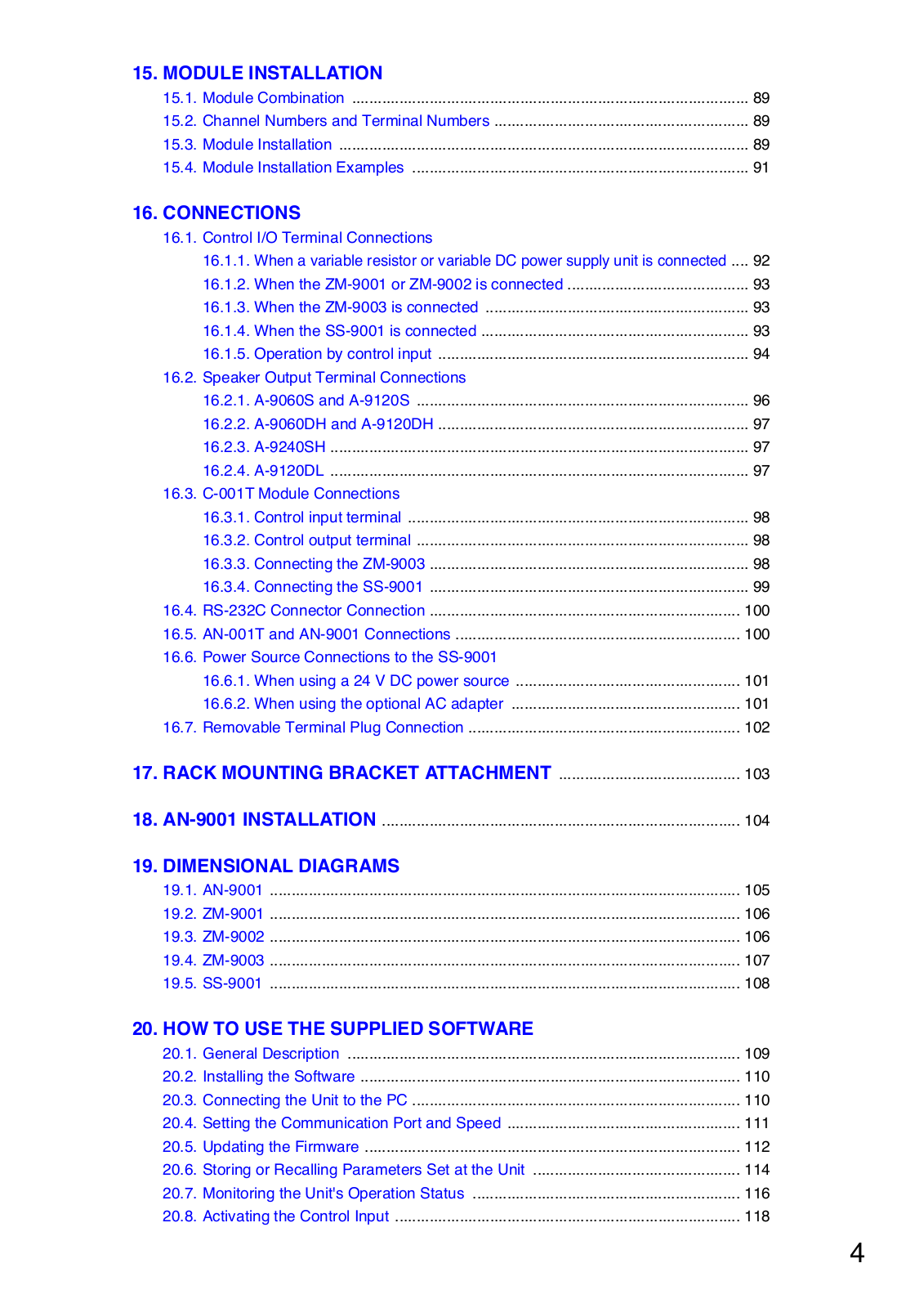
Table of contents
Loading...
TOA Electronics A-9060S, A-9120DL, A-9120S, A-9240SH User Manual
...
TOA Electronics User Manual
Download
Specifications and Main Features
Frequently Asked Questions
User Manual
Download
Loading...
+
hidden pages
Unhide
You need points to download manuals.
1 point = 1 manual.
You can buy points or you can get point for every manual you upload.
Buy points
Upload your manuals