

Indicates a potentially hazardous situation which,
if mishandled, could result in death or serious
personal injury.
WARNING
Indicates a potentially hazardous situation which,
if mishandled, could result in moderate or minor
personal injury, and/or property damage.
CAUTION
1. SAFETY PRECAUTIONS
•
Before installation or use, be sure to carefully read all the
instructions in this section for correct and safe operation.
• Be sure to follow all the precautionary instructions in
this section, which contain important warnings and/or
cautions regarding safety.
• After reading, keep this manual handy for future
reference.
• As a force of approx. 18 kg (39.68 lb) is applied to the
speaker receptacle at the time of speaker installation,
attach it in a location durable enough to withstand the
force. Doing otherwise may result in the unit falling
down, causing personal injury.
• Do not use other methods than specified to mount the
bracket. Extreme force is applied to the unit and the
unit could fall off, possibly resulting in personal injuries.
• Use nuts and bolts that are appropriate for the wall's
structure and composition. Failure to do so may cause
the speaker to fall, resulting in material damage and
possible personal injury.
• Ensure that all screws are securely tightened. If they
are loose after installation, the unit could fall down,
possibly resulting in personal injury.
• To avoid electric shocks, be sure to switch off the
amplifier's power when connecting speakers.
• Do not operate the unit for an extended period of time
with the sound distorting. This is an indication of a
malfunction, which in turn can cause heat to generate
and result in a fire.
• Do not stand or sit on, nor hang down from the unit as
this may cause it to fall down or drop, resulting in
personal injury and/or property damage.
• Thin type wall mount speaker with 5" cone speaker unit
• Two-way speaker system employing a balanced dome
tweeter and elliptical horn for high-frequency sound
reproduction in combination with a 5" cone speaker
unit ensures high-quality sound. (BS-1034 and BS1034S)
• The speaker's smoothly curved surface in combination
with its straight lines permits it to blend in with virtually
all modern buildings.
• Equipped with a speaker receptacle, providing speaker
cable connection and installation ease.
• Equipped with a lock mechanism, preventing the
speaker from being detached easily after installation.
• In-wall wiring, exposed wiring, or bridge wiring
available for speaker cable connection
• The input power (impedance) can be easily changed
by the rear-mounted rotary switch. (BS-1034 and BS1034S)
• The BS-634T has a built-in attenuator and can be
connected to a 3-wire and 2-wire systems.
2. FEATURES
INSTALLATION MANUAL
WALL MOUNT SPEAKERS
BS-634
BS-634T
BS-1034
BS-1034S
Thank you for purchasing TOA's Wall Mount Speaker.
Please carefully follow the instructions in this manual to
ensure long, trouble-free use of your equipment.
3. WIRING DIAGRAMS
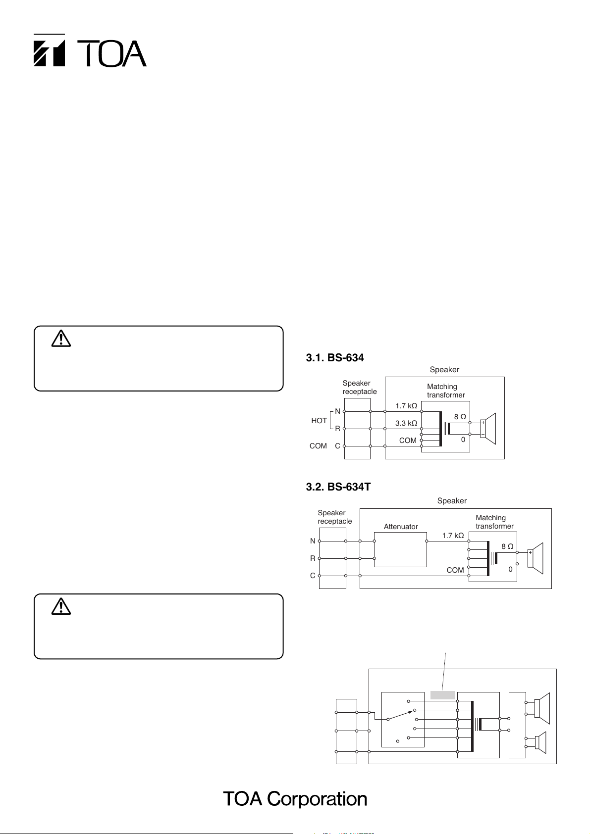
3.1. BS-634
3.2. BS-634T
3.3. BS-1034 and BS-1034S
Speaker
Speaker
receptacle
N
HOT
R
C
COM
Speaker
receptacle
N
R
C
1.7 kΩ
3.3 kΩ
Attenuator
COM
Matching
transformer
8 Ω
Speaker
1.7 kΩ
COM
0
Matching
transformer
8 Ω
0
Note
Never make 500 Ω connection in a 100 V line system.
Speaker
Rotary switch
(Factory pre-set)
500 Ω
3.3 kΩ
10 kΩ
COM
HOT
–
COM
Speaker
receptacle
N
R
C
1 kΩ
2 kΩ
Matching
transformer
8 Ω
Network
cercuit
0
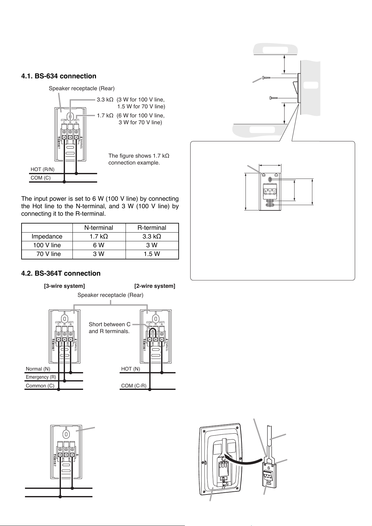
N-terminal R-terminal
Impedance 1.7 kΩ 3.3 kΩ
100 V line 6 W 3 W
70 V line 3 W 1.5 W
4. CONNECTION
4.1. BS-634 connection
5. INSTALLATION
Connect the speaker cable to the supplied speaker
receptacle. Connections differ depending on the speaker
to be installed. Read the descriptions of the
corresponding model.
The input power is set to 6 W (100 V line) by connecting
the Hot line to the N-terminal, and 3 W (100 V line) by
connecting it to the R-terminal.
4.2. BS-364T connection
4.3. BS-1034 and BS-1034S connections
Step 1. Attach the speaker receptacle to a wall.
[Notes on horizontal speaker mounting]
• Even if the speaker receptacle is attached horizontally,
the speaker may be tilted due to its weight unbalance
when attached to the receptacle.
• Be sure to attach the speaker so that its volume control
is positioned downward. (BS-634T only)
• When changing the logo direction, peel off the logo
carefully as it is affixed using double-faced tape. Then,
re-affix it in the right orientation.
[Exposed wiring]
Notch the top of the speaker receptacle using long-nose
pliers, then make connections.
Speaker receptacle (Rear)
3.3 kΩ (3 W for 100 V line,
1.5 W for 70 V line)
(COM)
CR
(HOT)
N
1.7 kΩ (6 W for 100 V line,
3 W for 70 V line)
TERMINAL
The figure shows 1.7 kΩ
connection example.
HOT (R/N)
COM (C)
Obstacle
170 mm (6.69") or more
Tapping screw 4 x 35
(accessory)
Wall
250 mm (9.84") or more
Obstacle
Notes on speaker receptacle mounting
"UP" mark
•
If the supplied tapping screws are not appropriate for the
70 (2.76")
120 (4.72")
66.7
83.5
(2.63")
(3.29")
construction of wall, separately prepare the appropriate
screws.
•
Install the speaker receptacle referring to its "UP" mark.
Position the receptacle at the specified distance away from
•
any object above and below it for vertical speaker mounting.
Keep the same distance to the right and left of the receptacle
(positioned sideways) for horizontal speaker mounting.
[3-wire system] [2-wire system]
Speaker receptacle (Rear)
(COM)
CR
(HOT)
N
Short between C
(COM)
and R terminals.
TERMINAL
Normal (N)
Emergency (R)
Common (C)
HOT (N)
COM (C-R)
Speaker receptacle
(COM)
CR
(HOT)
N
(Rear)
TERMINAL
CR
(HOT)
N
TERMINAL
Split the speaker cable into 2 branches just before it
enters the speaker receptacle so that it can be routed in
the cable-guide groove on the rear side of the speaker.
Speaker cable
Notch the top of the
speaker receptacle
using long-nose pliers.
HOT (N)
COM (C)
Speaker receptacle
Speaker (Rear)

Impedance 500 Ω 1 kΩ 2 kΩ 3.3 kΩ 10 kΩ
100 V line Never use this. 10 W 5 W 3 W 1 W
70 V line 10 W 5 W 2.5 W 1.5 W 0.5 W
6. DETACHING THE SPEAKER
Step 3. Hold and slide the speaker to insert its speaker
plug into the speaker receptacle.
Note
In this case, force the speaker onto the speaker
receptacle holding the speaker outer frame.
Step 4. Secure the speaker.
Turning the lock screw approximately about
3 counterclockwise turns using a Phillips
screwdriver causes the flap to rise up and stay
upright.
Caution
After speaker installation, be sure to make a
visual check that the flap rises to lock the
speaker completely.
Step 2. Change the input power (impedance) as
needed. (BS-1034 and BS-1034S only)
The input power (impedance) is factory-preset to
10 W (1 kΩ) for 100 V line.
When changing this setting, use a standard
screwdriver to turn the rotary switch on the
speaker's rear panel to the desired position.
Note
Be sure to follow the instructions below. Failure
to do so may cause damage to the speaker as
excessive input power is applied to it.
· Switch off the amplifier's power when changing
the input power.
· Never make 500 Ω connection in a 100V line
system, as excessive input power is applied to
the speaker, possibly resulting in damage.
Step 1. Turn the lock screw approximately 3 clockwise
turns.
The flap lies down and stays laid. (Refer to
"About lock mechanism.")
Step 2. Hold and slide the speaker to unplug it from the
speaker receptacle.
The lock mechanism is as shown below.
It prevents the speaker from being detached easily after
installation.
Note
Be sure to follow the instructions below. Failure to do so
may cause damage to the lock mechanism.
· Do not use an electric screwdriver when turning the
lock screw.
· Do not turn the lock screw more than the specified
turns.
About lock mechanism
Speaker (Rear)
Rotary switch
100V
70V
LINE
10W
5W
2.5W
0.5W
IMP.
OFF
500Ω
1kΩ
2kΩ
3.3kΩ
10kΩ
LINE
10W
5W
3W 1.5W
1W
[When fixing the speaker]
Turning the lock screw counterclockwise causes the
flap to rise up and move until it stops against the
other side of the recess.
Speaker (Rear)
Speaker plug
Speaker receptacle
Flap
Speaker receptacle
Lock screw
Speaker receptacle
Flap
Lock screw
Phillips screwdriver
[When detaching the speaker]
Turning the lock screw clockwise causes the flap to
lie down and move until it stops against the front side
of the recess. (Factory preset position)
Speaker receptacle
Flap
Lock screw
Phillips screwdriver

8. SPECIFICATIONS
Note: The design and specifications are subject to change without notice for improvement.
Note: The design and specifications are subject to change without notice for improvement.
BS-634 BS-634T
6 W
100 V line: 1.7 kΩ (6 W), 3.3 kΩ (3 W) 100 V line: 1.7 kΩ (6 W)
70 V line: 1.7 kΩ (3 W), 3.3 kΩ (1.5 W) 70 V line: 1.7 kΩ (3 W)
90 dB (1 W, 1 m)
120 – 18,000 Hz
12 cm (5") cone-type
M4 screw terminal, distance between barriers: 11 mm (0.43")
–
OFF, 1 (–12 dB), 2 (–6 dB), 3 (0 dB)
HIPS resin (fire resistant grade UL94 V-0 or its equivalent), off white (RAL 9010 or equivalent color)
Surface-treated steel plate, off white (RAL 9010 or equivalent color), paint
210 (w) x 330 (h) x 80 (d) mm (8.27" x 12.99" x 3.15")
1.3 kg (2.87 lb)
Speaker receptacle ............... 1, Tapping screw (4 x 35) ............... 2
Model No.
Rated Input
Rated Impedance
Sensitivity
Frequency Response
Speaker Component
Input Connector
Attenuation
Finish Enclosure
Net
Dimensions
Weight
Accessories
BS-1034 BS-1034S
10 W
100 V line: 1 kΩ (10 W), 2 kΩ (5 W), 3.3 kΩ (3 W), 10 kΩ (1 W)
70 V line: 500 Ω (10 W), 1 kΩ (5 W), 2 kΩ (2.5 W), 3.3 kΩ (1.5 W), 10 kΩ (0.5 W)
90 dB (1 W, 1 m)
120 – 20,000 Hz
Low frequency: 12 cm (5") cone-type, High frequency: Balanced dome-type
M4 screw terminal, distance between barriers: 11 mm (0.43")
HIPS resin (fire resistant grade UL94 V-0 or its HIPS resin (fire resistant grade UL94 V-0 or its
equivalent), off white (RAL 9010 or equivalent color)
equivalent), silver
Steel plate, off white (RAL 9010 or equivalent Steel plate, silver, paint
color), paint
210 (w) x 330 (h) x 80 (d) mm (8.27" x 12.99" x 3.15")
1.4 kg (3.09 lb)
Speaker receptacle ............... 1, Tapping screw (4 x 35) ............... 2
Model No.
Rated Input
Rated Impedance
Sensitivity
Frequency Response
Speaker Component
Input Connector
Finish Enclosure
Net
Dimensions
Weight
Accessories
Switch position 3 2 1 OFF
Sound volume High Middle Low Off
(0 dB) (–6 dB) (–12 dB)
7. VOLUME ADJUSTMENT (BS-634T ONLY)
Adjust the sound volume by rotating the rotary switch* on the speaker's
side panel using a standard screwdriver.
* It is positioned rightward as viewed from the front for vertical speaker
installation, or downward for horizontal speaker installation.
3
2
1
OFF
8.1. BS-634 and BS-634T
8.2. BS-1034 and BS-1034S
Note: Switch position is factory-preset to "3."
OFF
Rotary switch
Speaker
URL: http://www.toa.jp/
TEI REV1
533-06-159-80
 Loading...